 (1)
(1)
摘要 电缆终端内部缺陷会造成终端内部电场分布不均、局部温度升高与应力分布变化,可能引发局部放电造成绝缘击穿。为研究终端应力锥错位缺陷对电缆界面温度及应力分布的影响,分别建立了电缆终端安装不足与安装过盈情况下的电缆终端错位缺陷模型,并进行电-热-力多物理场耦合仿真分析。结果表明:电缆终端绝缘屏蔽层截断处是电缆终端的薄弱部位,终端界面温度和界面压力都会在绝缘屏蔽层截断处发生突变。当电缆终端存在安装不足缺陷时,终端屏蔽层截断处与应力锥根部之间会出现电场升高区域,在安装位置为-7.5 mm时界面温度最高,绝缘界面压力值升高,且安装位置为-2.5 mm时绝缘承受的压力值最大;当电缆终端存在安装过盈缺陷时,绝缘屏蔽层截断处会发生电场畸变,电场突变量随着偏移量的增加而增大,在安装位置为+5.0 mm时绝缘界面压力值最大,且界面压力突变量增加发生畸变。因此,在电缆终端实际设计安装与运行维护中,额外注意应力锥错位缺陷对终端内部应力分布的影响十分必要。
关键词:电缆终端 应力锥错位缺陷 电缆界面应力 电-热-力多物理场耦合
电缆终端内部绝缘屏蔽层剥除导致电场沿径向发散,使绝缘屏蔽层末端电场畸变、局部电场强度过大,进而引发局部放电,甚至造成绝缘击穿[1-2]。为了改善终端电场分布,电缆终端采用了多种降低电场畸变的处理措施,其中应力锥结构作为预制式冷缩电缆终端的重要组成部分,在电缆终端运行中能够缓解金属屏蔽层截断处的电场强度集中[3-5]。但在电缆终端安装施工中,受到安装工艺和运行条件的影响,电缆终端应力锥结构容易出现应力锥与绝缘屏蔽层位置的相对变化,即产生终端应力锥错位缺陷,影响应力锥处电场均匀分布;同时,缆芯与绝缘温度升高导致终端内部热应力分布变化,当终端内部存在缺陷时,将进一步影响终端内热应力分布。因此,研究电缆终端缺陷状态运行时的电场分布、温度分布、应力分布等关键性能,对分析终端故障原因具有重要意义。
有关电缆终端缺陷研究主要集中在研究缺陷状态下电缆终端的运行状态,其中大部分为电缆缺陷运行状态下的电场、温度场运行特性分析[6-13]。文献[6-8]开展电缆终端正常与缺陷状态下的电场运行特性仿真分析,得到了电缆终端缺陷处电场会发生畸变的结论,但其仅对电场进行分析,未考虑温度场对电场的影响。文献[9]建立高压直流电缆附件的电-热仿真模型,研究了不同温度下绝缘介质界面电荷积聚特性和局部电场畸变引起的附件内部电场的变化规律。文献[10]进行高压直流电缆电-热耦合仿真分析,计算了绝缘层厚度对电缆电场和温度场的影响规律,讨论了载流量和敷设方式对不同绝缘层厚度电缆温度场分布的影响。文献[11-13]考虑到电缆终端运行中电场与温度场间的相互作用,研究电-热耦合作用下电缆终端的电场、温度场分布特性,得到电缆终端缺陷部位温度升高会使终端材料的电气参数发生变化,进而影响终端内部的电场分布的结论,但其未考虑介质电导率和介电常数对电场的影响,同时大部分终端缺陷研究集中于电-热运行特性,对终端缺陷状态运行中的应力分布研究较少。
电缆终端在运行过程中因温度变化产生的热应力与形变会损伤电缆终端结构,甚至造成终端绝缘击穿[14-17],部分学者也对电缆附件实际运行中的应力分布开展了研究。文献[18-19]分别通过试验和仿真分析了电缆与硅橡胶附件在电缆接头的界面压力,得到界面压力与材料属性和安装位置相关。文献[20]分析了电缆接头运行过程中电磁场、温度场和应力场之间的相互耦合作用机理,得到电缆接头缺陷状态下的热-力运行特性规律。电缆终端缺陷会影响终端内部的应力分布,造成终端缺陷部位应力畸变更为严重,因此分析电缆终端缺陷状态下的热-力运行特性十分必要。
本文根据电缆终端各物理场间的耦合关系,建立应力锥安装不足与安装过盈情况下的电缆终端应力锥错位缺陷模型,并进行电-热-力多物理场耦合仿真分析。通过对比电缆终端界面最大电场强度与位置、界面温度变化以及界面压力和锥体应力分布,研究电缆终端错位缺陷下的热-力特性。
运行状态下的电缆终端因缆芯焦耳热损耗和绝缘介质损耗产生温度变化,进而在终端内部产生热应力与形变。同时温度变化影响电缆终端各处的电导率和介电常数等材料属性及终端电场分布;终端形变也将造成终端温度场求解区域的变化。因此,为计算电缆终端缺陷状态下内部的热应力分布,需采用电场-温度场-应力场耦合的方法,研究多物理场间相互耦合的作用机制。
为研究电缆终端应力锥错位缺陷状态下电-热-力运行特性,建立了电缆终端电磁场、温度场及应力场的多物理场耦合仿真模型。
电磁场控制方程为
 (1)
(1)
 (2)
(2)
 (3)
(3)
式中,J为总电流密度矢量;B为磁感应强度;E为电场强度矢量;σ为电导率,S/m; 为介电常数;A为矢量磁位;Je为外加电流密度;w为角频率,rad/s。
温度场控制方程为
 (4)
(4)
式中,r为材料密度,kg/m3;c为材料比热容,J/(kg·K);t为时间,s;T为温度,K;Q为热源体积产热,W/m3;l为导热系数,W/(m·K)。
终端结构产热包括缆芯焦耳热损耗与绝缘介质损耗,其产热率分别为
 (5)
(5)
 (6)
(6)
式中,Wc为焦耳热生成率;I为导体流过电流;α为电导率的温度系数;σ20为导体20℃下的电导率;Wp为介质损耗热生成率;C为电介质的电容;φ为电介质的电位;tanδ为电介质的介质损耗角正切值。
应力场控制方程为
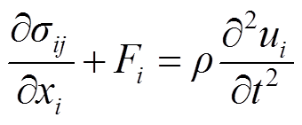 (7)
(7)
 (8)
(8)
 (9)
(9)
 (10)
(10)
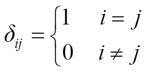 (11)
(11)
式中,u为位移;![]() 为应力张量;ε为应变张量;εΕ为弹性应变分量;εTh为热应变分量;
为应力张量;ε为应变张量;εΕ为弹性应变分量;εTh为热应变分量;![]() 为施加外力;E(T)为材料的杨氏模量;υ为泊松比;
为施加外力;E(T)为材料的杨氏模量;υ为泊松比;![]() 为材料线膨胀系数;
为材料线膨胀系数; 为温度变化。
电缆终端在运行过程中由于电磁损耗形成热源,导致终端内部温度分布变化,再由材料热膨胀引起终端内部应力与形变。因此电缆终端电场、温度场与应力场间的耦合作用形式主要分为以下两类。
1)电磁场与温度场间
确定电缆终端运行状态下的电磁损耗作为温度场控制方程中的热源项,其中电缆终端的电磁损耗包括终端缆芯的焦耳热损耗和终端绝缘材料介质损耗等,其计算式分别为式(5)和式(6)。
在终端电磁场计算时通过给定的终端电流及材料参数,根据终端热生成率计算式(5)和式(6),得到终端整体的热生成率,代入终端温度场控制方程式(4)得到终端运行时温度场分布。其中,终端导体的焦耳热损耗率与材料的电导率相关,而金属电导率等参数又为温度的函数;终端绝缘材料介质损耗与绝缘材料的介质损耗角正切值tanδ相关,而tanδ也随温度的变化而变化,电缆终端电场与温度场间互为耦合关系。电缆终端交联聚乙烯(Cross Linked Polyethylene, XLPE)绝缘层与硅橡胶附件相对介电常数随温度的变化如图1所示。
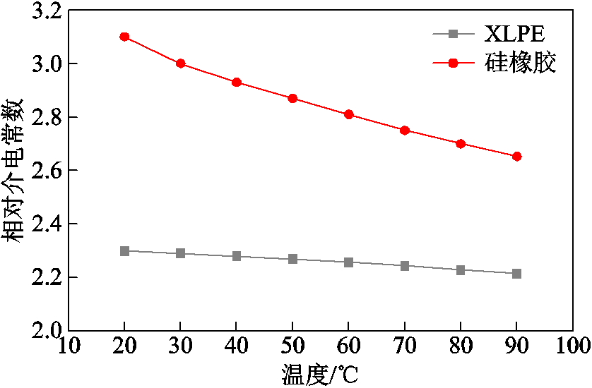
图1 XLPE绝缘层与硅橡胶附件相对介电常数变化
Fig.1 The relative dielectric constant change of XLPE insulation and silicone rubber
2)温度场与应力场间
将终端温度场求解得到的终端模型各点温度变化量代入热应变方程,得到终端内部各点处的位移分布与应力分布;而终端内部应力变化会引起终端形变,对电缆终端温度场离散求解区域造成影响,进而影响电缆终端温度场的计算结果。因此,电缆终端温度场与应力场间也互为耦合关系。
本文选用10 kV预制式电缆终端接头,依据终端实际尺寸在有限元仿真软件中建立10 kV电缆终端三维仿真模型如图2所示。10 kV预制式电缆终端结构如图3所示。

图2 电缆终端仿真模型
Fig.2 Cable terminal simulation model
图中,该10 kV预制式电缆终端仿真模型总长为350 mm,缆芯导体直径为18.4 mm,XLPE绝缘层厚度为4.5 mm,绝缘屏蔽层厚度为1 mm,制作成型的终端外表面最厚处直径为44 mm,最薄处直径为32 mm。电缆终端仿真分析所需的主要材料参数见表1。

图3 电缆终端结构
Fig.3 Internal structure diagram of cable terminal
表1 模型所用部分材料参数(20℃)
Tab.1 Material parameters of different parts of the model (20℃)

材料相对介电常数电导率/(S/m)导热系数/[W/(m·K)]弹性模量/MPa泊松比 铜导体11.26×1074001.26×1050.34 XLPE 2.310-150.291.07×1030.41 应力锥502.0×10-60.358.820.49 硅橡胶3.15.0×10-120.277.840.46
根据电缆终端接头实际运行条件,将终端外部温度设置为热力学温度293.15 K;将终端与空气接触,外表面的表面传热系数h取为5.6 W/(m2·K);绝缘屏蔽层接地处设为0电位;将缆芯导体通过电流设置为350 A的工频电流,电位设置为10 kV的工频交流电压;远离电缆终端的径向截面设置为磁绝缘;终端附件与电缆主绝缘间的界面初始压力取0.25 MPa,远离电缆终端处忽略轴向传热,即该处轴向位移分量为0,终端外表面设置为自由边界。
根据材料参数(见表1)、载荷设置和约束条件,开展电缆终端电磁场、温度场和应力场多物理场耦合仿真计算。研究结果表明,电缆终端接头从通流开始到运行36 h后,随着运行时间的增加,温升速率明显放缓。同时考虑仿真运行的复杂性,仿真时长设置为施加正常负荷电流开始至稳态运行36 h,最终得到电缆终端在额定条件下运行36 h后的电场、温度场及热应力场分布情况。
2.2.1 电场分布
仿真得到电缆终端正常运行下的电场强度分布与终端内沿绝缘交界面电场强度分布分别如图4a和图4b所示。
由图4可知,电缆终端内电场强度最高处位于缆芯导体表面,终端最大电场强度绝对值为4.21 MV/m;电缆终端内部电场在绝缘屏蔽层内均匀分布,而在终端绝缘屏蔽层截断处与应力锥端部电场分布发生突变,初步判断是因为绝缘屏蔽层截断破坏了电缆内金属屏蔽作用,导致该处电场发散;电缆终端界面电场强度与应力锥曲面电场强度沿电缆轴向逐渐降低,终端界面最大电场强度绝对值为2.25 MV/m,终端应力锥曲面电场在应力锥端部集中,电场强度升高。
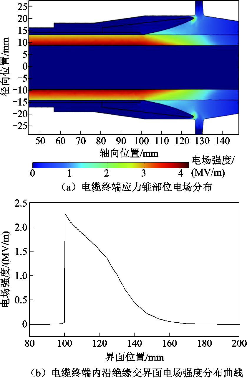
图4 电缆终端正常运行下电场强度分布
Fig.4 Electric field distribution of cable terminal under normal operation
2.2.2 温度场分布
仿真得到电缆终端正常运行下绝缘界面温度分布如图5所示。
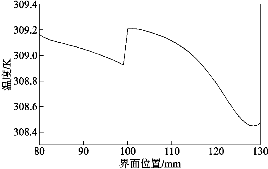
图5 电缆终端正常运行下温度场分布
Fig.5 Temperature field distribution of cable terminal under normal operation
由图5可知,电缆终端内温度最高处位于缆芯导体处,电缆终端正常运行至温度达到稳定时,电缆缆芯温度为312 K,其温升为18.85 K;电缆终端绝缘交界面温度在屏蔽层截断处发生突变,其原因是截断处电场强度发生突变导致温度变化,界面温度最大值为309.21 K,其温升为16.06 K。
2.2.3 应力场分布
仿真得到电缆终端正常运行下电缆绝缘表面压力分布如图6所示。
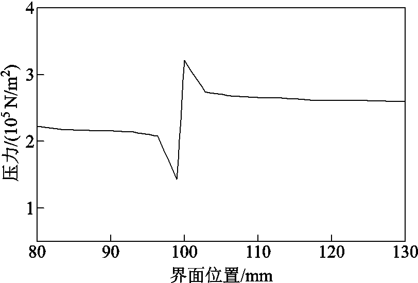
图6 电缆终端正常运行下压力分布
Fig.6 Stress distribution of cable terminal under normal operation
由图6可知,电缆终端由温度升高引发热膨胀导致热应力分布变化。在电缆终端导体表面由于缆芯与电缆绝缘层材料热膨胀系数不同,终端内部最大热应力位于缆芯处,为1.37×10⁷ N/m2;终端附件绝缘与电缆绝缘交界面受到材料热膨胀与安装附件初始界面压力的共同影响,在绝缘屏蔽层截断处绝缘表面压力发生突变,达到3.21×105 N/m2;在终端其余部位压力分布保持稳定。
由于安装工艺或运行条件的影响,电缆终端在实际运行中可能会出现应力锥错位缺陷。为了分析电缆终端不同程度错位缺陷对终端运行的影响,分别建立存在电缆终端安装不足-2.5、-5.0、-7.5 mm与电缆终端安装过盈+2.5、+5.0、+7.5 mm状态的终端应力锥错位缺陷模型,设置相同运行条件,仿真分析得到电缆终端在两类应力锥错位缺陷状态运行下电场、温度场和热应力分布情况。电缆终端模型安装不足-5.0 mm与安装过盈+5.0 mm缺陷示意图分别如图7a和图7b所示。
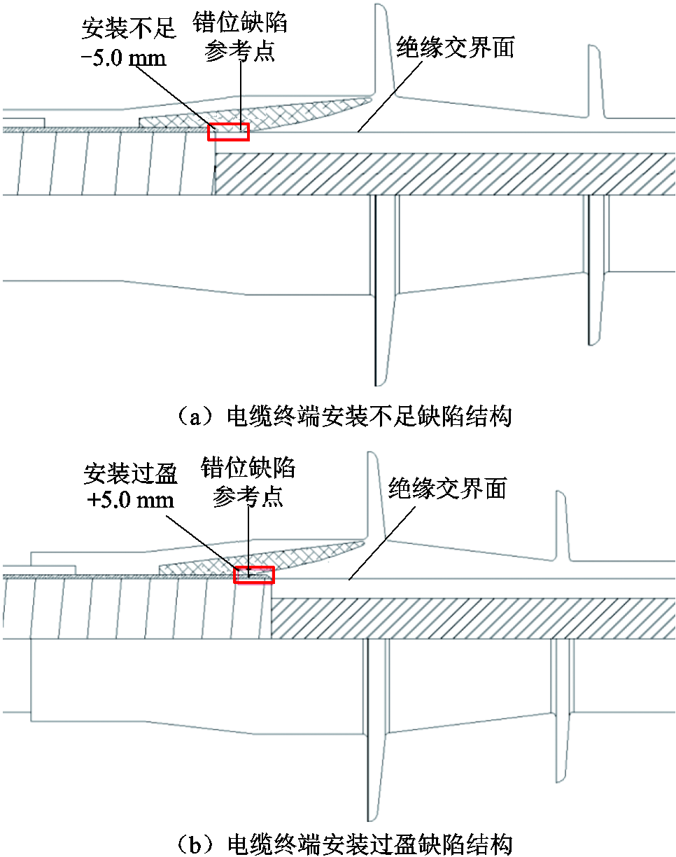
图7 电缆终端应力锥错位缺陷结构示意图
Fig.7 Cable terminal stress cone dislocation defect model
3.1.1 电场分布
仿真得到电缆终端安装不足情况下电场强度分布、终端沿绝缘交界面的电场强度分布与终端沿应力锥面电场强度分布分别如图8a、图8b和图8c所示。
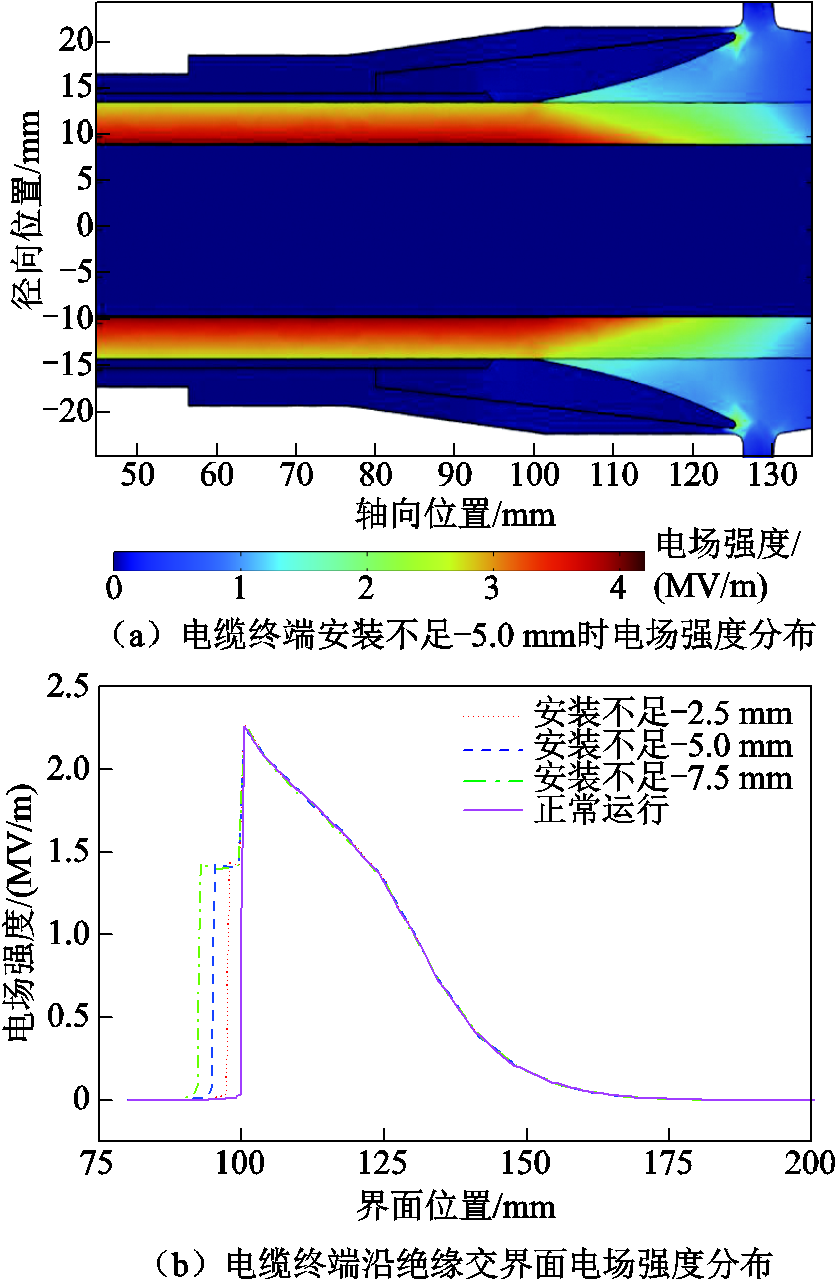
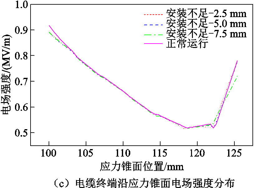
图8 电缆终端安装不足下电场强度分布
Fig.8 Electric field intensity distribution under insufficient cable terminal installation
由图8可知,在电缆终端安装不足状态运行时,绝缘界面最大电场强度位于应力锥根部,最大电场强度绝对值为2.25 MV/m;由于应力锥与半导电层未完全搭接,导致在屏蔽层截断处与应力锥根部之间出现电场升高区域,绝缘屏蔽层截断处界面电场强度绝对值升高为0.96 MV/m,对于不同程度安装不足缺陷的终端其绝缘界面电场变化趋势相似,但电场升高区域位置发生变化;电缆终端应力锥面在不同程度安装不足缺陷下的电场强度变化相同,且锥面最高电场强度与正常运行时相差不大,可得安装不足缺陷对应力锥面最大电场强度影响不大。
3.1.2 温度场分布
仿真得到电缆终端安装不足情况下沿绝缘交界面温度分布如图9所示。
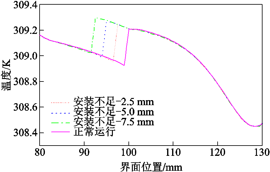
图9 电缆终端安装不足下温度场分布
Fig.9 Temperature field distribution under insufficient installation of cable terminals
由图9可知,在电缆终端安装不足状态运行时,绝缘界面温度突变位置随半导电层截断位置发生变化,且不同程度安装不足缺陷会影响终端绝缘交界面的温度值。在终端安装不足-2.5 mm时,绝缘截面温度最大值为309.23 K,其温升为16.08 K;在终端安装不足-7.5mm时,绝缘截面温度最大值为309.31 K,其温升为16.16 K。在终端电缆绝缘表面电场升高区域,温度沿电缆轴向下降变缓,相对正常运行电缆终端,该处温度升高。
3.1.3 应力场分布
仿真得到电缆终端安装不足情况下应力锥部位应力分布、终端绝缘表面压力分布曲线与终端绝缘界面应力分布曲线分别如图10a、图10b和图10c所示。
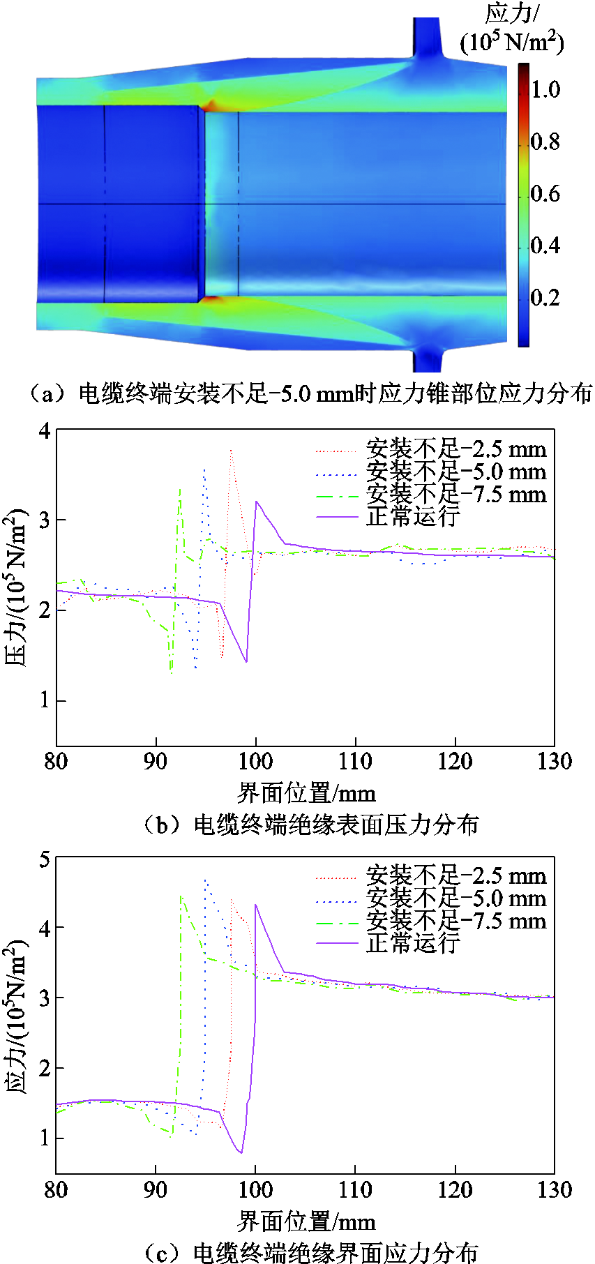
图10 电缆终端安装不足下应力分布
Fig.10 Tress distribution under insufficient installation of cable terminals
由图10可知,在终端安装不足状态运行时,相对于正常运行电缆终端,电缆本体绝缘承受压力变化增大,绝缘界面压力最大值位于终端半导电层截断处,且界面压力峰值随截断位置变化而发生变化。通过比较可得,电缆终端安装不足为-2.5 mm时电缆绝缘表面受压力值最大,达到3.78×10⁵ N/m2。而终端绝缘界面应力也会随着错位缺陷位置的变化而增加,其中电缆终端安装不足为-5.0 mm时电缆绝缘界面应力达到最大值,达到4.53×10⁵ N/m2。
由此可知,终端安装不足运行时,终端绝缘承受压力与界面应力都会升高且发生畸变,在长期负荷作用下,应力畸变将影响终端的安全稳定运行。电缆终端长期处于不均匀应力作用下会产生微孔或裂纹等,而带电粒子在绝缘材料裂纹中更容易获得加速,造成缺陷附近分子链断裂。以终端硅橡胶材料为例,表现为凝胶含量下降,其C-H键及Si-C键更容易断裂,该过程将会导致绝缘材料加速老化。
3.2.1 电场分布
仿真得到电缆终端安装过盈情况下电场强度分布、终端沿绝缘交界面电场强度分布与终端沿应力锥面电场强度分布分别如图11a、图11b和图11c所示。
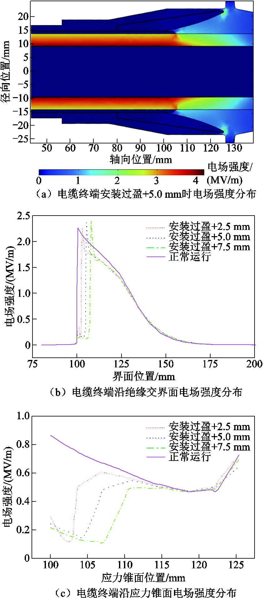
图11 电缆终端安装过盈下电场强度分布
Fig.11 Electric field intensity distribution under interference of cable terminal installation
由图11可知,在电缆终端安装过盈状态运行时,绝缘界面最大电场强度位于半导电层截断处,电缆终端安装过盈+2.5、+5.0、+7.5 mm时在绝缘屏蔽层截断处的电场强度绝对值分别为2.27、2.37、2.42 MV/m。由于应力锥根部与半导电层发生错位,应力锥结构对终端电场的均匀功能下降,导致终端界面电场的下降趋势相较正常运行电缆终端更快,表明安装过盈缺陷在终端屏蔽层截断处引起电场畸变。电缆终端在不同程度安装过盈缺陷的界面电场强度变化峰值不同,在安装过盈+7.5 mm时界面电场强度变化量最大。电缆终端在安装过盈状态下应力锥面电场强度最大值位于锥面中部而不再位于应力锥根部处,在安装过盈+2.5 mm时锥面电场强度变化量最大。
3.2.2 温度场分布
仿真得到电缆终端安装过盈情况下沿绝缘交界面温度分布如图12所示。
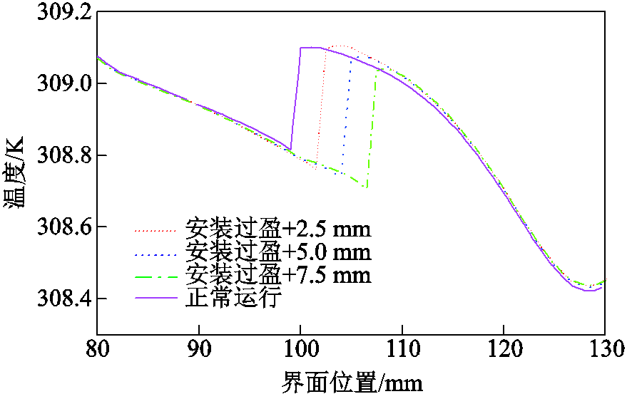
图12 电缆终端安装过盈下温度场分布
Fig.12 Temperature field distribution under interference during cable terminal installation
由图12可知,电缆终端安装过盈状态运行时,绝缘界面温度突变位置随屏蔽层截断位置变化而发生变化,在终端安装过盈+2.5 mm时绝缘表面温度最大值为309.11 K,其温升为15.96 K;在终端安装过盈+7.5 mm时绝缘表面温度最大值为309.04 K,其温升为15.89 K。电缆终端在安装过盈缺陷状态下的界面温度突变量相较于正常运行终端更大,但界面最高温度相较于正常运行终端略有上升。
由此可知,电缆终端在安装不足与安装过盈时都会产生终端绝缘界面温度升高现象,且温度升高趋势类似。电缆终端温度升高会导致绝缘材料内部发生氧化、热分解等化学反应,使材料内部分子结构发生硬度变化和龟裂等物理变化,进而引起绝缘材料的老化和性能降低;同时终端温度升高还会导致材料热膨胀变形增大,造成终端热应力的二次畸变。
3.2.3 应力场分布
仿真得到电缆终端安装过盈情况下应力锥部位应力分布、终端绝缘表面压力分布与终端绝缘界面应力分布分别如图13a、图13b和图13c所示。
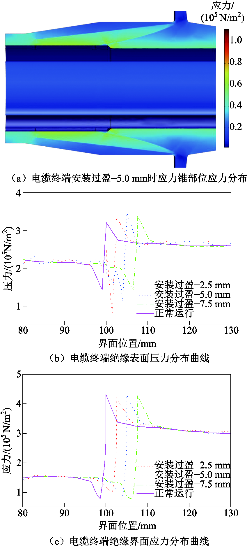
图13 电缆终端安装过盈下应力分布
Fig.13 Stress distribution diagram under interference during cable terminal installation
由图13可知,在电缆终端安装过盈状态运行时,绝缘表面压力与界面应力同样在绝缘屏蔽层截断处突变,绝缘屏蔽层超出应力锥部位处压力发生畸变。通过比较可得,电缆终端安装过盈为+5.0 mm时电缆绝缘表面承受压力最大,为3.46×10⁵ N/m2。在终端安装过盈运行时,相较于正常运行终端,绝缘界面应力突变位置随安装相对位置发生变化,但其界面应力变化量与正常运行相差不大。
由此可知,在终端安装过盈运行下,终端绝缘承受压力增加且畸变严重,在不均匀电场的共同作用下,会加速终端绝缘的损伤老化。根据相关文献发现,电缆终端绝缘击穿故障统计中终端内部的电树枝位置即为仿真计算得到的复合材料界面最大应力畸变的位置,因此,电缆终端结构设计制作时需注意应力锥错位的影响。
1)电缆终端安装不足状态运行时,绝缘界面在应力锥根部达到最大电场强度,电场强度绝对值为2.25 MV/m,且在绝缘屏蔽层截断处与应力锥根部之间出现电场升高区域;终端绝缘界面温度突变处随屏蔽层截断位置变化而变化,且不同程度安装不足缺陷会影响终端绝缘交界面的温度值,电缆终端在安装不足-7.5 mm运行时绝缘界面达到最高温度;在安装不足-2.5 mm时电缆绝缘表面受压力值最大,达到3.78×10⁵ N/m2;而终端绝缘界面应力也会随着错位缺陷位置的变化而增加,其中电缆终端安装不足为-5.0 mm时电缆绝缘界面应力达到最大值,达到4.53×10⁵ N/m2。
由此可知,电缆终端安装不足虽然会导致界面部分区域电场强度升高,但最大电场强度不变且不会影响应力锥均匀电场的能力,因此电缆终端在实际安装与运维中可以出现终端安装不足。但当安装不足缺陷较小时,终端绝缘界面应力最大值升高且表面受压值突变量增加,因此电缆终端在实际设计与安装中若出现安装不足缺陷,应保证应力锥根部超出绝缘屏蔽层截断处至少5.0 mm,以避免过小的安装不足缺陷在运行中出现较大的界面压力。
2)电缆终端在安装过盈状态运行时,安装过盈缺陷程度会影响界面电场强度最大值,在安装过盈+7.5 mm时绝缘界面电场强度绝对值突变量最大为2.42 MV/m;电缆终端界面电场的下降趋势相较正常运行电缆终端更快,表明安装过盈缺陷在终端屏蔽层截断处引起电场畸变;电缆终端安装过盈状态运行时,界面温度突变量相较于正常运行终端更大,界面最高温度相较于正常运行终端略有升高;绝缘表面压力最大值位于屏蔽层截断处,绝缘屏蔽层超出应力锥部分界面压力发生畸变,通过比较可得电缆终端安装过盈为+5.0 mm时绝缘表面受压力值最大,达到3.64×10⁵ N/m2;但其绝缘界面应力除突变位置变化外与最高点应力与正常运行相差不大。
综上所述,电缆终端安装过盈缺陷会导致界面最大电场强度升高,并会影响终端应力锥均匀电场的能力、引起电场畸变,因此电缆终端可以通过屏蔽层截断处的放电量来判断是否出现安装过盈缺陷。同时,终端安装过盈运行时绝缘承受压力增加且压力值突变明显,该处压力变化与升高的畸变电场叠加,更容易使终端绝缘发生破坏。因此,电缆终端实际设计与安装中不应出现安装过盈缺陷,在对实际电缆终端头进行设计施工与检测中需要额外注意。
3)总结仿真结果,电缆终端在安装不足与安装过盈运行下都会出现热应力升高与截断位置应力畸变量增加现象。根据仿真结果可认为,当高压电缆终端复合材料界面热应力发生畸变时,会导致附件内部复合材料径向和轴向受力增加。高压电缆终端内部应力增大,一方面,导致绝缘介质内部发生分子层面的物理破坏,形成微孔或裂纹等;另一方面,绝缘介质内部分子间的距离会相应增大,使电子更容易获得加速,造成缺陷附近分子链快速断裂,加速了绝缘材料的老化,便于电树枝进一步发展。由此认为,高压电缆终端在实际施工运行中,应力锥错位缺陷会导致复合界面的应力畸变,并加速绝缘材料老化,容易引发电缆终端绝缘故障。
参考文献
[1] 李国倡, 梁箫剑, 魏艳慧, 等. 配电电缆附件复合绝缘界面缺陷类型和位置对电场分布的影响研究[J]. 电工技术学报, 2022, 37(11): 2707-2715. Li Guochang, Liang Xiaojian, Wei Yanhui, et al. Influence of composite insulation interface defect types and position on electric field distribution of distribution cable accessories[J]. Transactions of China Electrotechnical Society, 2022, 37(11): 2707-2715.
[2] 刘凯, 张鹏鹏, 高波, 等. ZnO@PS粒子分散特性及改性乙丙橡胶绝缘性能研究[J]. 电工技术学报, 2023, 38(8): 2265-2276. Liu Kai, Zhang Pengpeng, Gao Bo, et al. Research on the dispersion characteristics of ZnO@PS particles and the insulation characteristics of modified ethylene propylene rubber[J]. Transactions of China Electrote-chnical Society, 2023, 38(8): 2265-2276.
[3] 何金良, 杨霄, 胡军. 非线性均压材料的设计理论与参数调控[J]. 电工技术学报, 2017, 32(16): 44-60. He Jinliang, Yang Xiao, Hu Jun. Progress of theory and parameter adjustment for nonlinear resistive field grading materials[J]. Transactions of China Electrotechnical Society, 2017, 32(16): 44-60.
[4] 韩宝忠, 傅明利, 李春阳, 等. 硅橡胶电导特性对XLPE绝缘高压直流电缆终端电场分布的影响[J]. 高电压技术, 2014, 40(9): 2627-2634. Han Baozhong, Fu Mingli, Li Chunyang, et al. Effect of silicone rubber’s electric conductance characteristic on electric field distribution inside XLPE insulated HVDC cable termination[J]. High Voltage Engineering, 2014, 40(9): 2627-2634.
[5] 胡军, 赵孝磊, 杨霄, 等. 非线性电导材料应力锥改善电缆终端电场强度分布[J]. 高电压技术, 2017, 43(2): 398-404. Hu Jun, Zhao Xiaolei, Yang Xiao, et al. Improving the electric field strength distribution of cable terminals by stress cone of nonlinear conductivity material[J]. High Voltage Engineering, 2017, 43(2): 398-404.
[6] 李长明, 伍国方, 李春阳, 等. XLPE绝缘高压直流电缆终端内缺陷对电场分布的影响[J]. 电机与控制学报, 2018, 22(12): 62-67.Li Changming, Wu Guofang, Li Chunyang, et al. Effect of the defects inside XLPE insulated HVDC cable termination on the electric field distribution[J]. Electric Machines and Control, 2018, 22(12): 62-67.
[7] 黄韬, 郝艳捧, 肖佳朋, 等. 10kV XLPE电缆终端典型安装缺陷的工频局部放电特征对比研究[J]. 电网技术, 2022, 46(6): 2420-2428. Huang Tao, Hao Yanpeng, Xiao Jiapeng, et al. Comparative study on partial discharge characteristics of typical installation defects in 10 kV XLPE cable terminals under power frequency[J]. Power System Technology, 2022, 46(6): 2420-2428.
[8] Ciuba M, Wojciechowski M, Owsiński M, et al. Excitation type and results of simulated electric field distribution in MV cable termination[J]. Przegląd Elektrotechniczny, 2020, 96(4): 119-122.
[9] 李国倡, 王家兴, 魏艳慧, 等. 高压直流电缆附件XLPE/SIR材料特性及界面电荷积聚对电场分布的影响[J]. 电工技术学报, 2021, 36(14): 3081-3089. Li Guochang, Wang Jiaxing, Wei Yanhui, et al. Effect of material properties of XLPE/SIR and interface charge accumulation on electric field distribution of HVDC cable accessory[J]. Transactions of China Electrotechnical Society, 2021, 36(14): 3081-3089.
[10] 魏艳慧, 郑元浩, 龙海泳, 等. 绝缘层厚度对高压直流电缆电场和温度场分布的影响[J]. 电工技术学报, 2022, 37(15): 3932-3940. Wei Yanhui, Zheng Yuanhao, Long Haiyong, et al. Influence of insulation layer thickness on electric field and temperature field of HVDC cable[J]. Transactions of China Electrotechnical Society, 2022, 37(15): 3932-3940.
[11] Zachariades C, Peesapati V, Gardner R, et al. Electric field and thermal analysis of 132 kV ceramic oil-filled cable sealing ends[J]. IEEE Transactions on Power Delivery, 2020, 36(1): 311-319.
[12] Yang Fan, Cheng Peng, Luo Hanwu, et al. 3-D thermal analysis and contact resistance evaluation of power cable joint[J]. Applied Thermal Engineering, 2016, 93: 1183-1192.
[13] 郭蕾, 李丽妮, 邢立勐, 等. 基于电-热场联合分析的EPR中压电缆终端异常热点仿真分析及优化[J]. 电力自动化设备, 2020, 40(7): 211-224. Guo Lei, Li Lini, Xing Limeng, et al. Simulation analysis and optimization based on electric-thermal field for abnormal distortion hot spots of EPR medium voltage cable terminal[J]. Electric Power Automation Equipment, 2020, 40(7): 211-224.
[14] 周远翔, 张征辉, 张云霄, 等. 热-力联合老化对硅橡胶交联网络及力学和耐电特性的影响[J]. 电工技术学报, 2022, 37(17): 4474-4486. Zhou Yuanxiang, Zhang Zhenghui, Zhang Yunxiao, et al. The effect of combined thermal-mechanical aging on the cross-linking network and mechanical and electrical properties of silicone rubber[J]. Transactions of China Electrotechnical Society, 2022, 37(17): 4474-4486.
[15] 刘昌, 惠宝军, 傅明利, 等. 机械应力对硅橡胶高压电缆附件运行可靠性的影响[J]. 高电压技术, 2018, 44(2): 518-526. Liu Chang, Hui Baojun, Fu Mingli, et al. Influence of mechanical stress on the operation reliability of silicone rubber high voltage cable accessories[J]. High Voltage Engineering, 2018, 44(2): 518-526.
[16] 王霞, 余栋, 段胜杰, 等. 高压电缆附件设计环节中几个关键问题探讨[J]. 高电压技术, 2018, 44(8): 2710-2716. Wang Xia, Yu Dong, Duan Shengjie, et al. Dealing with some key design problems in HV cable accessory[J]. High Voltage Engineering, 2018, 44(8): 2710-2716.
[17] 梁振, 彭杰, 胡军. 基于接触电阻模型的电缆接头复合材料界面温度及应力分布仿真研究[J]. 高压电器, 2021, 57(12): 147-155. Liang Zhen, Peng Jie, Hu Jun. Simulation study on interface temperature and stress distribution of cable joints based on contact resistance model[J]. High Voltage Apparatus, 2021, 57(12): 147-155.
[18] 贾志东, 张雨津, 范伟男, 等. 10kV XLPE电缆冷缩中间接头界面压力计算分析[J]. 高电压技术, 2017, 43(2): 661-665. Jia Zhidong, Zhang Yujin, Fan Weinan, et al. Analysis of the interface pressure of cold shrinkable joint of 10 kV XLPE cable[J]. High Voltage Engineering, 2017, 43(2): 661-665.
[19] 谢强, 王晓游, 傅明利, 等. 高压电缆接头过盈配合及硅橡胶附件力学性能计算[J]. 高电压技术, 2018, 44(2): 498-506. Xie Qiang, Wang Xiaoyou, Fu Mingli, et al. Interference fit and mechanical property computation of silicone rubber accessory in HV cable joint[J]. High Voltage Engineering, 2018, 44(2): 498-506.
[20] 杨鑫, 刘真, 梁振, 等. 电-热耦合作用下高压电缆接头运行中复合界面热应力分布的仿真计算[J]. 电机与控制学报, 2020, 24(10): 100-108. Yang Xin, Liu Zhen, Liang Zhen, et al. Simulation calculation of thermal stress distribution of composite interface in operation of high voltage cable joint under electro-thermal coupling[J]. Electric Machines and Control, 2020, 24(10): 100-108.
Abstract As an important part of the prefabricated cable terminal, the stress cone structure can alleviate the concentration of the electric field strength at the cut-off of the insulation shielding layer during the operation of the cable terminal. However, in the installation and construction of the cable terminal, due to the influence of the installation process and operating conditions, the cable terminal will have a stress cone dislocation defect, which will affect the uniform distribution of the terminal electric field; at the same time, the increase in cable core and insulation temperature will lead to a change in the thermal stress distribution in the terminal and affect the thermal stress distribution in the terminal. At present, the research on cable terminal defects mainly focuses on electro thermal aspects, while there are few studies on their internal stress distribution. In this paper, the electro-thermal-mechanical multi-physical field coupling simulation analysis of the dislocation defect cable terminal is carried out to analyze the changes in electric field strength, temperature distribution, and stress distribution in the operation of terminal defects.
During the operation of the cable terminal, the heat source is formed due to the electromagnetic loss, which leads to the change of the internal temperature of the terminal, and then the thermal stress and deformation of the terminal are generated by the thermal expansion of the material. Firstly, the physical field control equations of the cable terminal are established and the coupling relationship between the physical fields is analyzed. Then, the cable terminal model and the stress cone dislocation defect model are established, and the material parameters and boundary conditions are set and simulated.Finally, by comparing the maximum electric field strength, temperature change, and interface pressure distribution under the condition of a cable terminal defect, the influence of a stress cone dislocation defect on terminal temperature and stress is obtained, and suggestions are given for cable terminal installation, operation and maintenance.
The simulation results show that when the cable terminal is in normal operation, the electric field strength of the insulation interface changes abruptly at the cut-off position of the shielding layer. The maximum temperature of the terminal cable core is 312 K, and the maximum thermal stress is 1.37×10⁷ N/m2. The terminal interface temperature and interface pressure are abruptly changed at the cut-off position of the insulation shielding layer.When the installation size of the cable terminal is too small, the maximum electric field strength of the insulation interface is 2.25 MV/m, and the electric field rise zone appears between the cut-off of the insulation shielding layer and the root of the stress cone. When the dislocation size of the cable terminal is −7.5 mm, the temperature of the insulation interface reaches its highest value. When the terminal dislocation size is −2.5 mm, the insulation surface pressure value is the largest, reaching 3.78×10⁵ N/m2. When the dislocation size of the cable terminal is +7.5 mm, the maximum electric field intensity of the insulation interface increases to 2.42 MV/m, and distortion occurs at the truncation of the insulation shielding layer. When the installation size of the terminal is too large, the sudden change in the interface temperature will increase, the pressure of the cable terminal on the insulation surface will increase, and the pressure of the insulation interface will be obviously distorted. When the dislocation size of the cable terminal is +5.0 mm, the insulation interface pressure reaches a maximum of 3.46×10⁵ N/m2. According to the above conclusions, the dislocation defect of the cable terminal will seriously affect the stress distribution of the terminal and superimpose with the electric field and temperature field, resulting in terminal insulation damage and aging. Therefore, the design and installation of the cable terminal should pay attention to the occurrence of stress cone dislocation defects, especially to avoid the electric field distortion and stress distortion caused by the excessive installation size of the terminal.
keywords:Cable terminal, stress cone dislocation defect, cable interface stress, electro-thermal-mechanical multi-physics coupling
DOI:10.19595/j.cnki.1000-6753.tces.230738
中图分类号:TM853
吉林省科技发展计划资助项目(20230203136SF)。
收稿日期 2023-05-23
改稿日期 2023-07-18
祝 贺 男,1978年生,教授,研究方向为电缆检修和电气绝缘等。E-mail:zhuhe1215@163.com
何峻旭 男,1999年生,硕士研究生,研究方向为电缆终端缺陷。E-mail:hejunxue0710@163.com(通信作者)
(编辑 李 冰)