图1 变压器半波饱和原理
Fig.1 Schematic diagram of transformer half-cycle saturation
摘要 高空电磁脉冲晚期成分(HEMP E3)效应会在变压器中性点与大地构成的回路中产生地磁感应电流(GIC),严重时会使变压器铁心半波饱和,进而导致励磁电流严重畸变、无功损耗急剧增加、局部过热和振动加剧等后果。为准确地分析电力变压器在HEMP E3作用下的无功损耗特性,该文搭建了HEMP E3对500 kV电力变压器作用的电磁暂态仿真模型,基于IEC 61000-2-9给出的标准HEMP E3波形,定量分析了感应电场幅值、上升时间、下降时间以及变压器带负载情况等对电力变压器的影响规律。分析结果表明,HEMP E3 作用下500 kV变压器无功损耗与GIC呈正相关性,且无功损耗波形滞后于感应电场的变化;HEMP E3感应电场的下降时间对500 kV变压器无功损耗的影响远超上升时间;负载阻抗的阻值相同时,容性负载下的励磁电流和无功损耗幅值最大,感性负载下幅值最小。研究结果可为进一步评估HEMP E3对电力系统稳定性的影响提供重要依据。
关键词:变压器 地磁感应电流 高空电磁脉冲晚期成分 无功损耗
高空电磁脉冲(High-altitude Electromagnetic Pulse, HEMP)由爆炸高度在地表30 km以上的核爆产生,其晚期成分(HEMP E3)电场具有低频特性,作用时间在一秒到百秒之间。HEMP E3会在交流输电系统中产生地磁感应电流(Geomagnetically Induced Current, GIC),使变压器绕组中出现低频分量,从而造成变压器的半波饱和,进而导致无功损耗增加[1-4]、局部过热[5-7]、谐波增加[8-10]、产生振动和噪声等后果[11-12]。HEMP E3作用下变压器的半波饱和问题,相较于直流输电系统运行方式和太阳磁暴等产生的直流偏磁效应,在作用过程上有相似之处,但HEMP E3-GIC具有峰值量级相对较高、持续时间短等特点,需要在变压器偏磁分析中计及这些时变特征。
国内外学者关于HEMP E3对电力系统的危害开展了初步研究,陈宇浩等总结了HEMP E3影响电网的故障链模式[13];T. R. Hutchins等通过建立电力系统机电暂态模型来评估HEMP E3对电力系统的影响[14];Metatech公司给出了HEMP E3对美国不同的城市或地区电网的GIC威胁水平评估[15]。变压器是电力系统中的关键设备,同时也是HEMP E3的首要作用对象,因此需要准确深入地评估HEMP E3对变压器的影响。李泓志等确定了不同铁心形式和联结绕组的变压器耐受直流偏磁能力的强弱[16];R. S. Girgis等指出地磁扰动期间的额外无功损耗可能会导致系统电压降低,极端情况下甚至可能导致电压崩溃[17]。因此无功损耗特性分析是HEMP E3作用期间变压器的主要研究问题之一。文献[18-22]证明了变压器的无功损耗与其绕组中的GIC呈线性关系,并给出了针对不同铁心结构变压器的比例系数K值。然而,上述文献在开展地磁灾害对变压器无功损耗影响评估时,将GIC视为稳态直流,而未充分考虑瞬态电场波形下变压器的动态特性。文献[23-24]的研究结果表明,不考虑GIC的准直流特性会降低风险评估精度。
因此为研究实际变压器在遭受HEMP E3入侵时的磁通饱和现象及无功损耗等重要特性,本文基于电磁暂态方法,搭建能够反映HEMP E3量级高、持续时间短等特点的变压器电路模型,定量分析瞬态影响下变压器的无功损耗特性。利用IEC 61000-2-9标准E3波形,采用500 kV的星形-三角形联结变压器进行仿真分析,针对电场可能发生的变化情况以及变压器带载情况等因素进行分析,为进一步评估HEMP E3对电力系统稳定性的影响以及制定应对措施提供支撑。
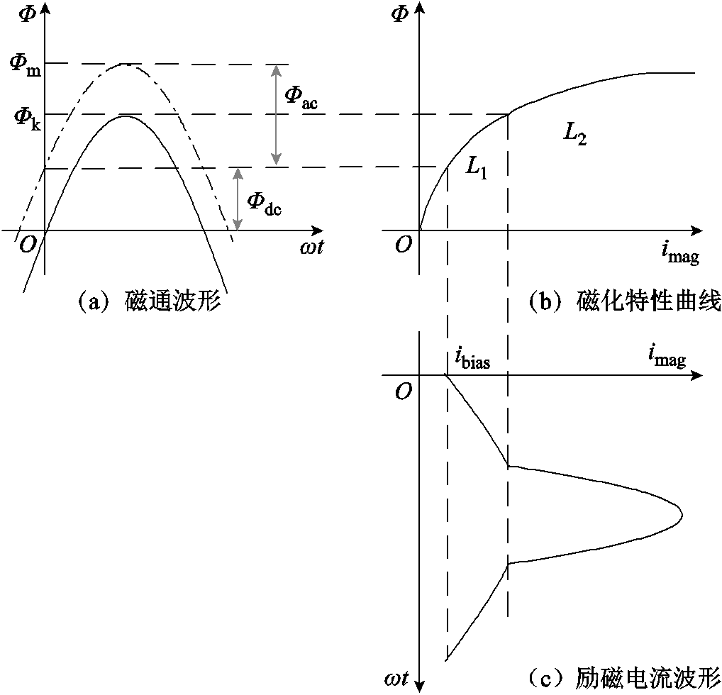
半波饱和为交流变压器的一种不正常运行状态。当变压器中性点流入准直流电流时,其在铁心硅钢片中会产生相应的直流磁通,产生偏磁现象,严重时使变压器铁心发生饱和。变压器半波饱和原理如图1所示。图1a中实线为不存在直流磁通情况下的磁通波形,点画线为受到直流磁通影响后的磁通波形;图1b为铁心硅钢片的磁化特性曲线,L1、L2分别为铁心非饱和、饱和电感,数值上分别等于磁通达到临界磁通Φk前后的磁化特性曲线斜率大小;图1c为考虑半波饱和情况下励磁电流的畸变波形[1-2],ibias为直流磁通Φdc对应的直流电流分量。

图1 变压器半波饱和原理
Fig.1 Schematic diagram of transformer half-cycle saturation
当GIC流入变压器时,铁心中便会产生相应的直流磁通量Φdc,与峰值为Φac的额定交流磁通量相叠加,使得铁心中总磁通量的峰值达到Φm。当磁通量超过临界值Φk时,铁心进入饱和状态。
2009年,国际电工委员会SC77C分委员会颁布了高空电磁脉冲和高功率电磁环境的系统级敏感性评估标准IEC 61000-2-9[25]。该标准也给出了HEMP E3的双指数函数波形表达式及参数,分别见式(1)及表1。
 (1)
(1)
其中


表1 标准HEMP E3的波形参数
Tab.1 Parameters of standard HEMP E3 waveform

参数τ/sE0/(V/m)a/s-1b/s-1k Ei(t)t-10.040.0221.058 Ej(t)t-10.013 260.0150.029.481
由式(1)和表1可得标准HEMP E3的波形如图2所示。电场强度峰值为38 mV/m,上升时间约为0.9 s,正脉冲宽度为20 s,负脉冲宽度为130 s。
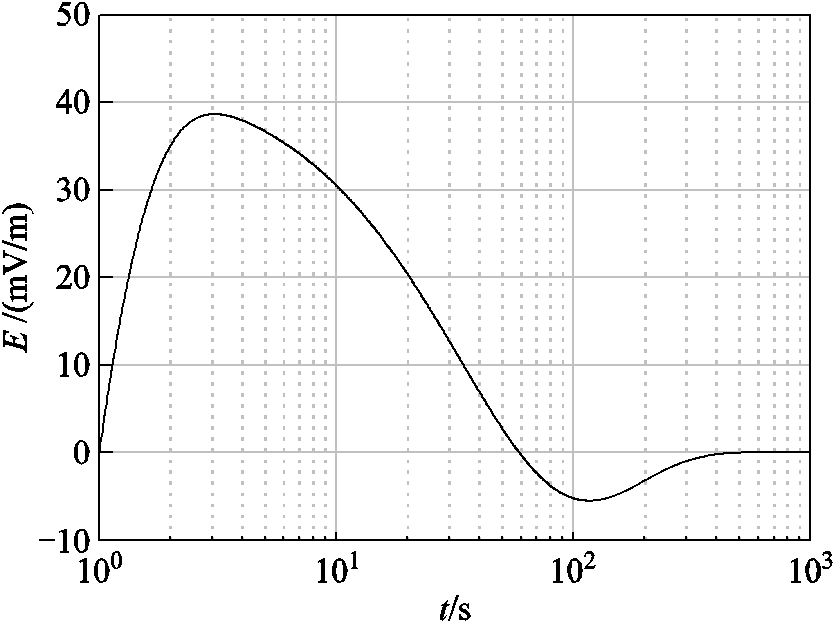
图2 标准HEMP E3的波形[25](IEC 61000-2-9)
Fig.2 Standard HEMP E3 waveform[25] (IEC 61000-2-9)
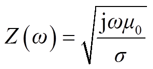
标准IEC 61000-2-9中的E3波形仅适用于电导率为10-4 S/m的均匀大地,对于其他电导率的均匀大地,根据平面波理论[26-27],E3作用下产生的感应电场为
 (2)
(2)
 (3)
(3)
式中,Z(ω)为大地波阻抗;ω为角频率,μ0为真空磁导率;σ为大地电导率;H(ω)为磁场强度;B(ω)为磁感应强度;E(ω)为感应电场强度。
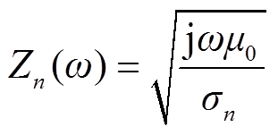
对于一维分层大地电导率模型,假设大地结构是分层均匀的,各层具有不同的电导率和厚度,最底层的大地厚度趋于无穷大,故该层中的波阻抗为
 (4)
(4)
式中,Zn(ω)为底层大地波阻抗;σn为底层大地的电导率。
得到底层波阻抗Zn后,通过式(5)从底层出发,反复递推,即可得到每层大地波阻抗[28-29]。
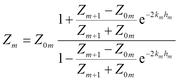 (5)
(5)
其中

式中,Zm为第m层大地波阻抗;km为第m层大地传播系数,m=n-1, n-2,…, 1;hm为第m层大地厚度。
得到各层大地波阻抗后,可利用IEC标准计算分层大地电导率模型下的E3感应电场[30-31],计算步骤如图3中“电场参量计算”过程所示。首先,已知IEC标准下E3感应电场强度波形E3(t)和对应的均匀大地电导率σ0,根据式(2)可计算出均匀大地波阻抗Z0,再根据式(3)即可计算出E3磁感应强度B(ω)。然后根据每层大地电导率模型的相关参数,利用式(4)和式(5)可计算出地表大地波阻抗Z1(ω),将B(ω)和Z1(ω)代入式(3)再进行反快速傅里叶变换(Inverse Fast Fourier Transform, IFFT),即可得到基于一维分层大地电导率模型下的E3感应电场强度。

图3 HEMP E3作用下变压器无功损耗计算流程
Fig.3 Calculation procedure of reactive power loss of transformer under HEMP E3
地表的HEMP E3感应电场会在输电线路、变压器的接地点和大地构成的回路中产生GIC。GIC的频率很低,在0.001~1 Hz之间,与工频电流相比,可被视为直流电流。在已知电场的情况下,可将此电场等效成网络中的电压源,从而将GIC计算转换为电路问题进行求解,计算步骤如图3中“电路参量计算”过程所示。根据感应电场的作用机制,线路感应电压UDC为感应电场强度沿输电线路的积分[32],即
 (6)
(6)
式中,E为感应电场强度;Σ为输电线路路径;dl为输电线路长度微分。接下来可以通过电路分析方法评估系统各支路中的GIC水平。
本文采用星形-三角形联结的电力变压器,三相变压器的一次侧连接三相工频交流电源,二次侧连接变压器额定负载。等效脉冲电源通过与输电线路串联作用于变压器,通过一次绕组与大地构成回路,从而在变压器星形侧产生GIC,其原理如图4所示。
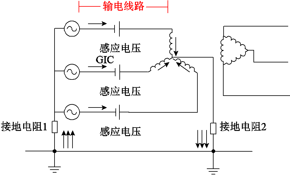
图4 HEMP E3作用下单个变压器中GIC流通路径
Fig.4 GIC flowpath in a power transformer under HEMP E3
假设A、B、C三相系统的参数相同,则流经变压器每一相中的GIC无论是大小还是方向都完全相同。考虑到E3感应电场的低频特性,通常只考虑输电线路和变压器等元件的电阻参数[33],根据节点导纳法,可计算得到流过变压器绕组的GIC为
 (7)
(7)
式中,RL、RT1、Rg分别为输电线路电阻值、变压器一次侧电阻值和总接地电阻值;rL为输电线路单位长度的电阻值。
变压器在铁心饱和的时段,由于励磁支路电感减小,会产生大量附加的无功损耗。在直流偏磁状态下,忽略铁心磁滞和涡流损耗,变压器的无功损耗Q为
 (8)
(8)
式中,Φph为励磁支路磁通的基频分量;Iph为励磁电流的基频分量。已有研究表明[3-4],在GIC恒定且幅值相对较低的情况下,变压器无功损耗稳态值与流过其中性点的GIC可近似视为线性关系。
本文针对星形-三角形联结变压器进行仿真计算,变压器的参数见表2,输电线路选用三华电网的500 kV线路参数[33],HEMP E3采用IEC标准波形,研究了感应电场峰值、波前波后时间(以第一个脉冲为准)以及负载性质对变压器的影响。由于计算 HEMP E3 效应的过程即为分析在传输线上HEMP E3感应电场的作用效果,所以可以将电场的作用等效为电压源,将 HEMP E3 效应的计算转换为电路问题,从而通过等效的变压器模型仿真分析HEMP E3对变压器无功损耗的影响。
表2 500 kV电力变压器参数
Tab.2 500 kV power transformer parameters

参数数值 额定容量/(MV·A)277 额定频率/Hz50 高压侧额定电压/kV500 低压侧额定电压/kV220 线圈电阻(pu)0.003 8 线圈电抗(pu)0.165 8
首先验证节点导纳法计算结果的正确性,假定直流电场强度E=2 V/m,可以得到500 kV变压器的GIC与输电线路的关系如图5所示。现有文献给出了我国交流输电线路的一般输送容量及输电距离,超出实际距离的理论值用点画线表示。
从图5中可以看到,电磁暂态仿真结果与纯电阻电路假设下的理论计算值相对应。随着输电长度的增大,GIC并没有线性增大。在输电线路较短的情况下,rLl RT1+Rg,GIC与输电线路近似为线性关系;当输电线路较长时,GIC与线路长度为非线性关系;当输电线路长度达到一定程度后,GIC达到极限值即GIC=E/rL。
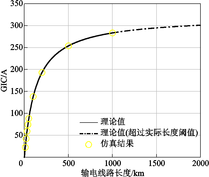
图5 变压器中GIC与输电线路长度的关系
Fig.5 Relationship between GIC of the transformer and transmission line
为了研究感应电场幅值对GIC效应的影响,在变压器中性点施加不同的直流电压,结果如图6所示。随着GIC增大,无功损耗呈线性增大,饱和速率也在增大,具体关系见表3。
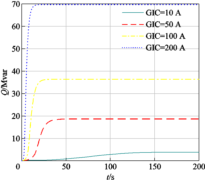
图6 直流GIC下变压器的无功损耗
Fig.6 Reactive power loss of transformer under GIC (DC)
表3 直流电场作用下的稳态值及上升时间
Tab.3 Steady-state values and rising time under DC electric field

GIC/AQ/MvarQ的上升时间/s 103.8690.32 5018.7516.60 10036.469.50 20069.765.66
根据GIC-K值的工程算法[3]进行拟合后得到无功损耗为
 (9)
(9)
式中,Qloss为变压器的GIC无功损耗;Q0为变压器未发生饱和时的无功损耗;该式中的0.34即为比例系数K。GIC-Q关系与文献[3-4, 8]基本吻合,进一步验证了理论模型的正确性。
E3作用下变压器无功损耗的计算首先基于HEMP E3感应电场和电网的电阻电路模型用节点导纳法计算GIC,再通过K值法计算得到变压器无功损耗。本文对比了该方法的无功损耗计算结果与电磁暂态模型的计算结果,以GIC最大幅值为200 A的E3电场为例,上述两种方法的无功损耗结果对比如图7所示。由图7可知,采用两种分析方法得到的无功损耗波形相近,但在感应电场正负极性改变期间(t=70~150 s)产生较大误差。这是由于电场陡前沿和极性反转时间内,非线性元件存在过渡过程。此外,无功损耗仿真结果滞后于节点导纳法和K值法的结果,这是由于无功损耗不仅与当前时刻的电场有关,还取决于过去时刻的电场[24]。综合以上结论,在HEMP E3分析中考虑非线性元件的电磁暂态仿真比节点导纳法和K值法更准确。
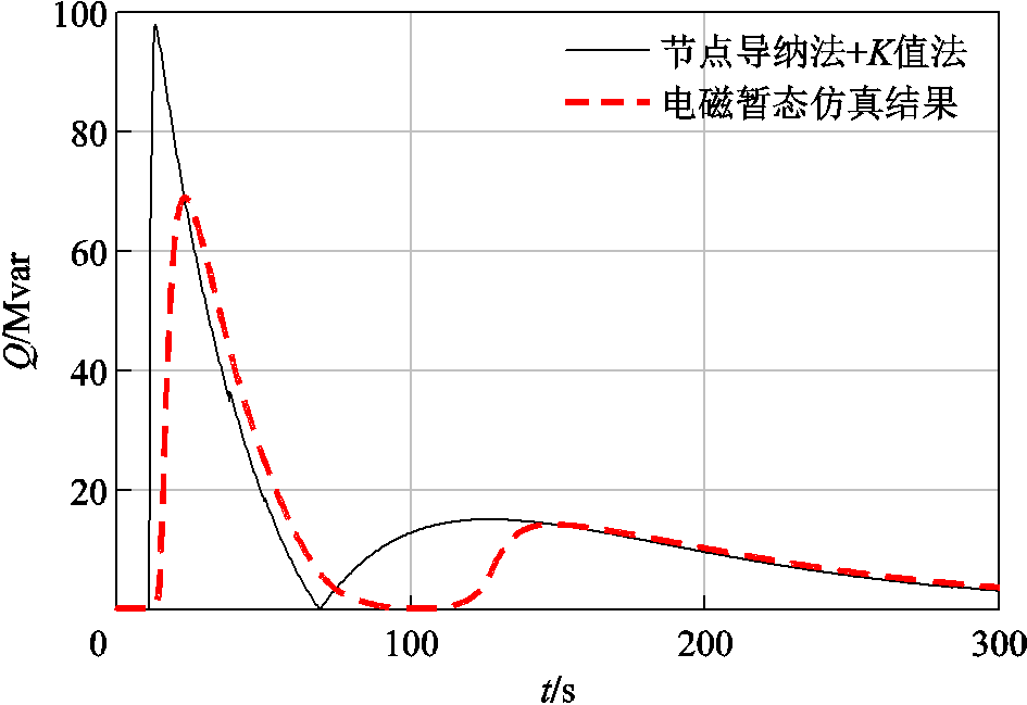
图7 不同方法下变压器无功损耗结果对比
Fig. 7 Comparison of reactive power loss of the transformer with different methods
实际的HEMP E3电场会受到非均匀大地电导率和海岸效应等的影响,波形整体上会发生变化,根据本文1.2节分析,对均匀大地模型和分层大地电导率模型下HEMP E3感应电场进行计算。均匀大地模型选用大地电导率分别为σ=0.000 1、0.000 5、0.001 S/m;分层大地模型选用三华大地的M2和M12板块[33],具体参数见表4。
不同大地模型下的感应电场如图8所示。由图8可知,在实际情况下,感应电场除了幅值改变,波形也发生改变。本节首先分析HEMP E3感应电场幅值变化的情况,用于表征均匀大地模型中不同电导率的影响。以100 km输电线路为基准,选取IEC标准波形下0.5倍、1倍、2倍、5倍和10倍感应电压,施加于变压器,研究HEMP E3的感应电场峰值对变压器作用效果的影响,仿真结果如图9和表5所示。
表4 分层大地电导率模型参数
Tab.4 Parameters of layered conductivity model

深度/km大地电导率/(S/m) 京—津—冀—鲁北(M2)鄂东南—赣北(M12) [0,30)0.000 50.02 [30,90)0.001 30.001 3 [90,150)0.000 250.000 5 [150,∞)0.30.3
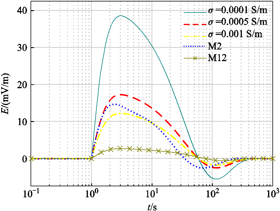
图8 不同大地模型下的感应电场强度
Fig.8 Induced electric fields under different earth models

图9 HEMP E3不同峰值情况下变压器无功损耗对比
Fig.9 Comparison of reactive power loss under different peak values of HEMP E3
仿真结果表明,HEMP E3电场幅值越大,无功损耗相应增大;根据表5分析可知,随着E3感应电场增大,GIC-Q的比例关系与直流电场作用的差距逐渐显著。同时,E3作用下的变压器无功损耗并不是无限增大,该上限与变压器深度饱和后的空心电感有关。
表5 不同感应电压峰值情况下变压器无功损耗
Tab.5 Reactive power loss of the transformer under different induced voltage peaks

感应电压峰值/kVGIC峰值/A无功损耗峰值Qm/MvarQm/GIC/ (Mvar/A) 1.9(0.5倍)1 564.6387.010.25 3.8(1倍)2 535.0500.420.20 7.6(2倍)3 615.9555.810.15 19(5倍)4 801.8561.490.12 38(10倍)5 377.0557.790.10
本节主要研究E3感应电场上升时间和下降时间对变压器无功损耗特性的影响,通过改变HEMP E3表达式中的ai和bi,分别控制下降和上升时间,改变输电线路上的感应电场波形。
ai=0.02、0.04、0.16 s-1的感应电场强度和无功损耗分别如图10a和图10b所示。通过图10b中的无功损耗变化可以得出,参数ai的取值越大,对应HEMP E3波形的下降时间就越短,这会导致无功损耗的下降时间明显减少,波形整体产生显著变化。不同ai对应的无功损耗指标对比见表6。根据表6,当ai从0.02 s-1变化为0.16 s-1时,感应电场下降时间减少80.8%,无功损耗下降时间减少80.3%,幅值减小20.3%。HEMP E3波形下降时间的改变对变压器无功损耗下降时间具有较大影响。
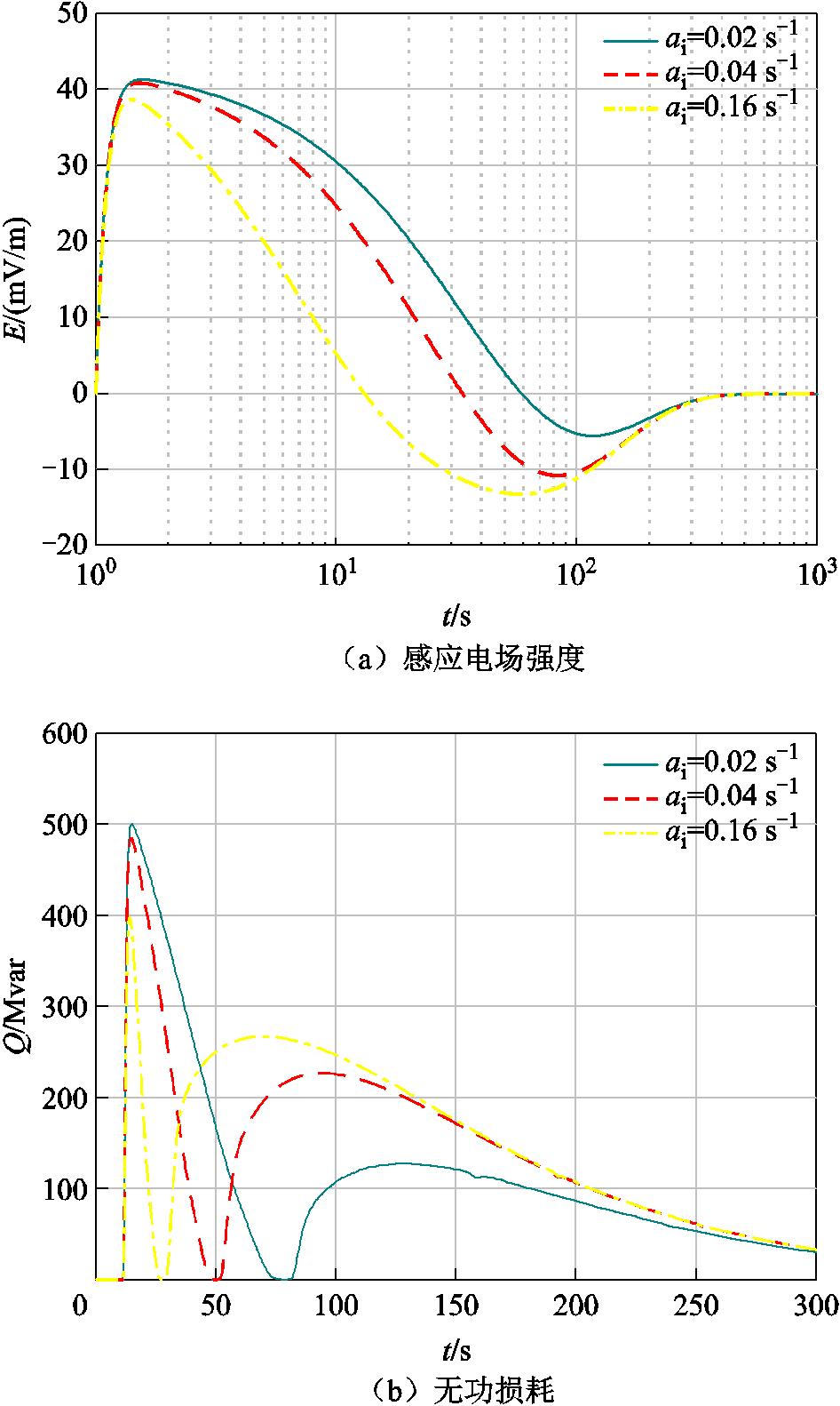
图10 HEMP E3作用下不同ai对变压器无功损耗的影响
Fig.10 Influence of different ai on reactive power loss under HEMP E3
表6 不同ai对应的无功损耗指标对比
Tab.6 Comparison of reactive power loss indexes corresponding to ai

ai/s-1感应电场下降时间/s无功损耗峰值Qm/Mvar无功损耗下降时间/s 0.0240.62500.4242.96 0.0422.94485.0723.79 0.167.81399.018.46
bi=0.5、1、2、4、8 s-1的感应电场强度和无功损耗分别如图11a和图11b所示。当所取bi参数越大,对应HEMP E3波形的上升时间就越小,这会导致无功损耗的上升时间略有减小,但变化幅度相比HEMP E3下降时间不同取值时的现象微弱很多。不同bi对应的无功损耗指标对比见表7。从表7可知,当bi从0.5 s-1变为4时,感应电场上升时间减少83.1%,无功损耗上升时间减小44.3%,幅值增大了7.3%。所以HEMP E3波形上升时间的改变对变压器无功损耗上升时间的影响相对较小。
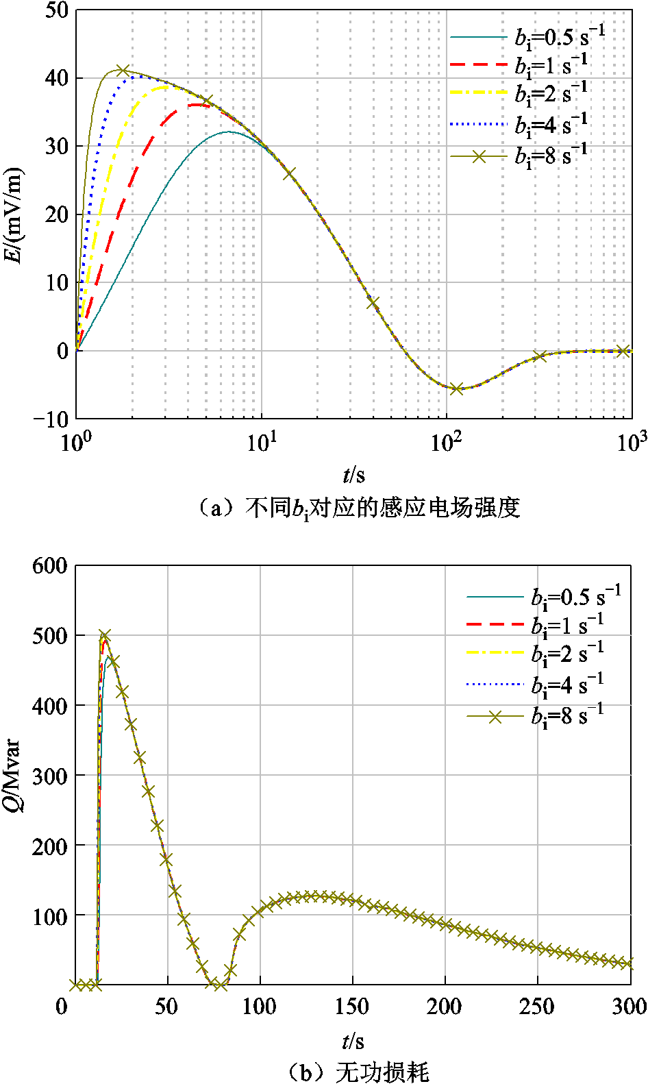
图11 HEMP E3作用下不同bi对变压器无功损耗的影响
Fig.11 Influence of different bi on reactive power loss under HEMP E3
表7 不同bi对应的无功损耗指标对比
Tab.7 Comparison of reactive power loss indexes corresponding to bi

bi/s-1感应电场上升时间/s无功损耗峰值Qm/Mvar无功损耗上升时间/s 0.52.90468.862.44 11.67491.941.80 20.92500.421.49 40.49503.031.36 80.26503.951.35
为了分析HEMP E3作用下不同性质负载对变压器的影响,低压侧分别被施加纯电阻、纯电感、纯电容三种负载[34-35],分别模拟变压器的额定运行状态、过无功和无功不足三种工况。为保证变压器尽可能在额定状态下运行,该变压器负载阻抗为58.24 Ω。
t=10 s时施加E3电场,无E3和有E3作用的变压器励磁电流分别如图12和图13所示。从图12可以看出,纯电阻和纯电感负载情况在无偏磁情况下励磁电流为幅值很小的正弦波,而变压器在纯电容负载情况正负半波都出现明显的尖顶波,而且幅值大于另外两种情况。对称饱和现象的出现是由于变压器本身存在漏感,带容性负载后进入过电压状态,因此即使没有外加直流电压,励磁电流也会在正负半波增大。
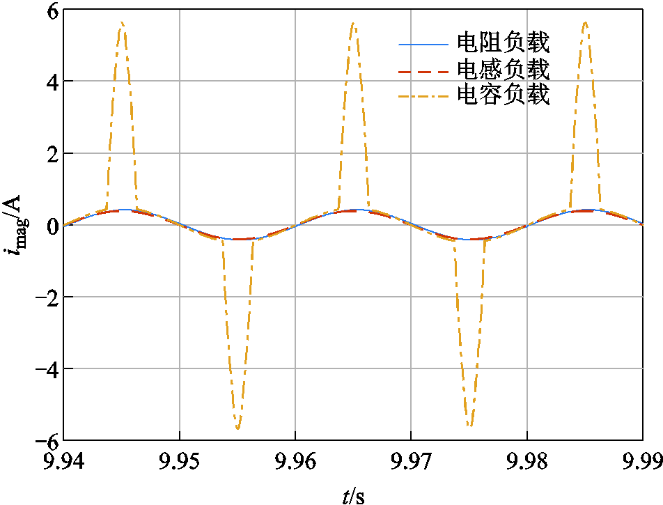
图12 无HEMP E3作用时不同性质负载对应的变压器励磁电流
Fig.12 Transformer magnetization current with loads of different properties without HEMP E3
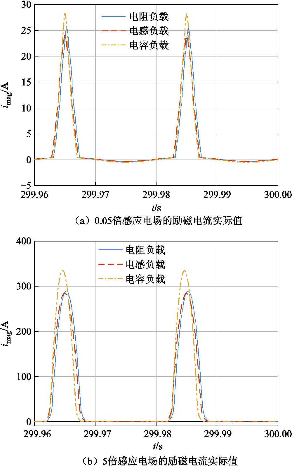
图13 HEMP E3作用下变压器不同负载的励磁电流
Fig.13 Transformer magnetization current with loads of different properties under HEMP E3
图13反映了在E3电场作用下,变压器带三类负载的励磁电流情况。从图13a可以看出,在E3等效电压幅值较小时,即线路长度较短或电场强度幅值较低的情况,此时三种负载下励磁电流均出现幅值很大的尖顶波且只出现在正半波。出现半波饱和现象是因为E3电场产生直流流入绕组线圈,铁心中便会产生相应的直流磁通量,当总磁通超过膝点磁通,励磁电感变小,励磁电流产生半波饱和现象。图13b反映的是E3等效电压幅值较大时的励磁电流情况,可见偏磁现象更加明显,阻性、感性和容性负载下励磁电流的峰值分别为289.5 A、284.7 A和334.5 A,电感和电阻负载情况下励磁电流的差值相对于幅值来说较小。
E3作用下不同性质负载对应的变压器无功损耗的有效值如图14所示,其波形与E3作用下的电场相似,不同负载类型对无功损耗的幅值有明显影响。当阻抗大小相同时,电容负载情况时的无功损耗幅值最大,电阻负载情况次之,电感负载情况最小。这是由于变压器本身的漏感远大于漏阻,因此容性负载下总阻抗降低;变压器自身阻抗与阻性负载相位差为90°左右,总阻抗增大;变压器自身阻抗与感性负载基本同向,阻值增长更大,因此励磁电流幅值相对小,无功损耗幅值也相对小。图14b反映出E3等效电压幅值较大时的无功损耗情况,阻性、感性和容性负载下无功损耗均达到饱和,峰值分别为579.9 Mvar、539.6 Mvar和711.8 Mvar。
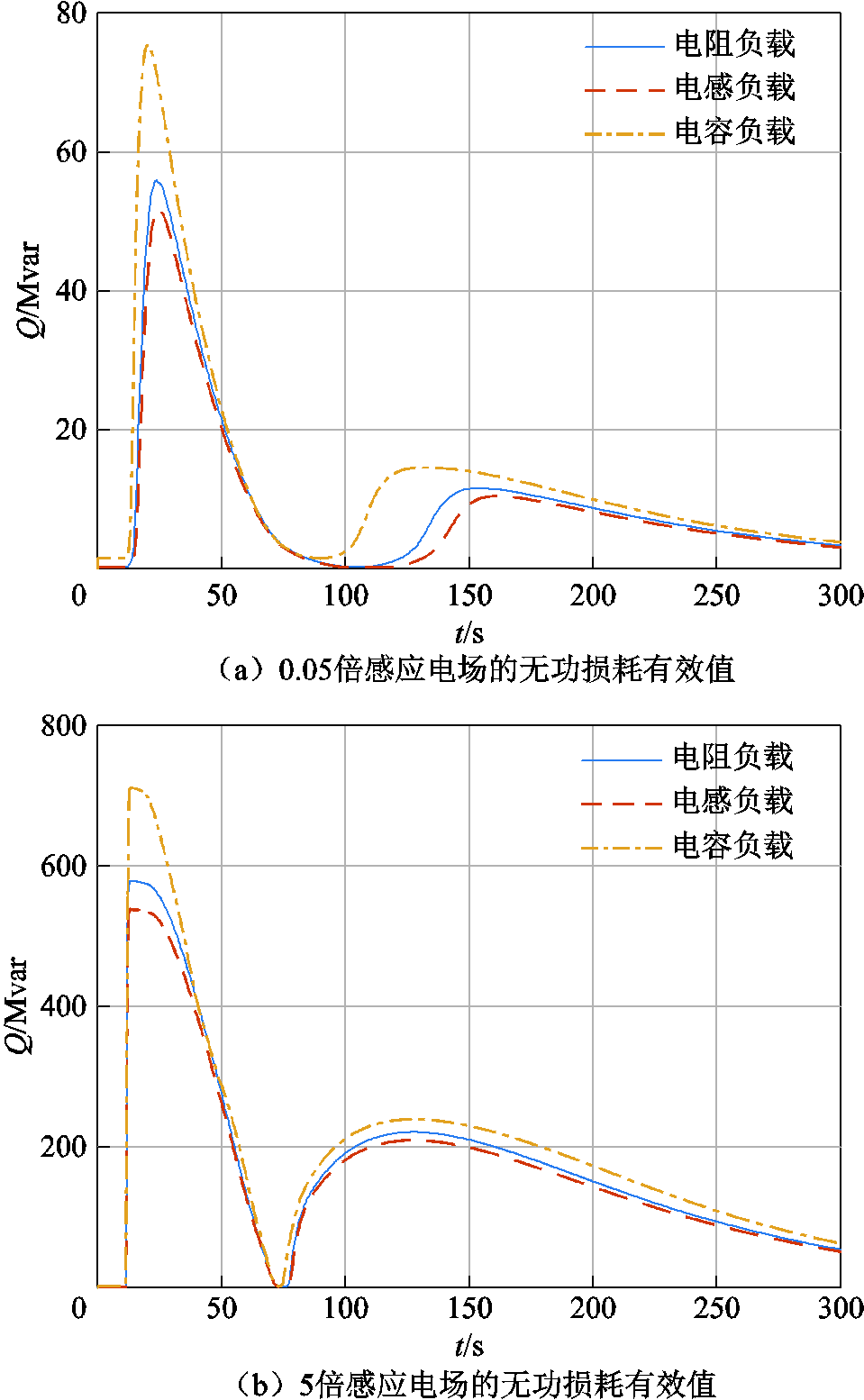
图14 HEMP E3作用下不同性质负载对应的无功损耗
Fig.14 RMS of reactive power loss with different loads under HEMP E3
针对HEMP E3作用下变压器无功损耗特性,本文通过对500 kV变压器进行电磁暂态仿真分析,基于E3作用于均匀大地和一维分层大地产生的感应电场,针对E3可能的感应电场参数变化情况以及变压器负载情况,分析了变压器励磁电流和无功损耗的变化规律,得出以下结论:
1)输电线路较短时,GIC与线路长度正相关,但线路长度增大到一定程度时,GIC达到饱和值。在幅值较低的直流GIC作用下,变压器无功损耗与其绕组中GIC保持近似线性关系;但E3电场与直流电场作用下无功损耗波形不同,并且E3的GIC-Q关系用单一数值表示会产生误差。这是由于E3电场具有脉冲特性,且存在极性反转,需要考虑电路中非线性元件的过渡过程,采用电磁暂态仿真能够更准确地评估E3作用下变压器的偏磁效应。
2)E3波形下降时间的改变对变压器无功损耗产生很大影响,而上升时间的改变对变压器无功损耗的影响相对较小。
3)在施加HEMP E3电场以后,不同负载类型导致变压器励磁电流发生不同程度的畸变。由于负载阻抗的相位差,阻抗值相同时容性负载下的励磁电流和无功损耗幅值最大,感性负载下幅值最小。同时感应电场越强,励磁电流的峰值越高,偏磁现象更加明显。
HEMP E3作用下变压器的半波饱和现象,会引发多种复杂效应,除了变压器励磁电流畸变和无功损耗增加,还会导致谐波增多、局部温升、振动和噪声等现象,这些效应将在未来工作中进一步研究。
参考文献
[1] 师泯夏, 吴邦, 靳宇晖, 等. 直流偏磁对变压器影响研究综述[J]. 高压电器, 2018, 54(7): 20-36, 43. Shi Minxia, Wu Bang, Jin Yuhui, et al. Research summary on the impacts of DC magnetic bias on transformer[J]. High Voltage Apparatus, 2018, 54(7): 20-36, 43.
[2] 王泽忠, 黄天超. 变压器地磁感应电流-无功功率动态关系分析[J]. 电工技术学报, 2021, 36(9): 1948-1955. Wang Zezhong, Huang Tianchao. Analysis of geomagnetically induction current-reactive power dynamic relationship of transformer[J]. Transactions of China Electrotechnical Society, 2021, 36(9): 1948-1955.
[3] 刘连光, 朱溪, 王泽忠, 等. 基于K值法的单相四柱式特高压主体变的GIC-Q损耗计算[J]. 高电压技术, 2017, 43(7): 2340-2348. Liu Lianguang, Zhu Xi, Wang Zezhong, et al. Calculation for reactive power loss of single-phase four limbs UHV main transformer due to geomagnetically induced currents with parameter K[J]. High Voltage Engineering, 2017, 43(7): 2340-2348.
[4] 刘教民, 朱溪, 刘洪正, 等. 电力变压器的GIC-Q损耗算法的研究综述[J]. 高电压技术, 2018, 44(7): 2284-2291. Liu Jiaomin, Zhu Xi, Liu Hongzheng, et al. Calculation methods for reactive power loss of transformers due to geomagnetically induced current[J]. High Voltage Engineering, 2018, 44(7): 2284-2291.
[5] 朱涛, 王丰华. 地磁感应电流作用下大型变压器的温升特性计算[J]. 电工技术学报, 2022, 37(8): 1915-1925. Zhu Tao, Wang Fenghua. Calculation of temperature rise of large transformer under geomagnetically induced current[J]. Transactions of China Electro-technical Society, 2022, 37(8): 1915-1925.
[6] 王丰华, 周翔, 高沛, 等. 基于绕组热分布的改进油浸式变压器绕组热点温度计算模型[J]. 高电压技术, 2015, 41(3): 895-901. Wang Fenghua, Zhou Xiang, Gao Pei, et al. Improved thermal circuit model of hot spot temperature in oil-immersed transformers based on heat distribution of winding[J]. High Voltage Engineering, 2015, 41(3): 895-901.
[7] 王泽忠, 李明洋, 宣梦真, 等. 单相四柱式变压器直流偏磁下的温升试验及仿真分析[J]. 电工技术学报, 2021, 36(5): 1006-1013. Wang Zezhong, Li Mingyang, Xuan Mengzhen, et al. Temperature rise test and simulation of single-phase four-column transformer under DC-bias[J]. Trans-actions of China Electrotechnical Society, 2021, 36(5): 1006-1013.
[8] Dong Xuzhu, Liu Yilu, Kappenman J G. Comparative analysis of exciting current harmonics and reactive power consumption from GIC saturated transformers[C]// 2001 IEEE Power Engineering Society Winter Meeting, Conference Proceedings (Cat. No.01CH37194), Columbus, OH, USA, 2001: 318-322.
[9] 颜广兴. 直流偏磁条件下变压器的谐波分析[D]. 广州: 华南理工大学, 2018.
[10] 张晓宇, 郑超, 莫品豪, 等. 直流偏磁对变压器保护的影响及直流偏磁保护改进[J]. 电力系统自动化, 2021, 45(4): 148-154. Zhang Xiaoyu, Zheng Chao, Mo Pinhao, et al. Influence of DC magnetic bias on transformer protection and improvement of DC magnetic bias protection[J]. Automation of Electric Power Systems, 2021, 45(4): 148-154.
[11] 张冰, 刘连光, 肖湘宁.地磁感应电流对变压器振动、噪声的影响[J]. 高电压技术, 2009, 35(4): 900-904. Zhang Bing, Liu Lianguang, Xiao Xiangning. Effects of geomagnetically induced current on the vibration and noise of transformers[J]. High Voltage Engin-eering, 2009, 35(4): 900-904.
[12] 李冰, 王泽忠, 刘海波, 等. 直流偏磁下500kV单相变压器振动噪声的试验研究[J]. 电工技术学报, 2021, 36(13): 2801-2811. Li Bing, Wang Zezhong, Liu Haibo, et al. Experiment on vibro-acoustic characteristic of 500kV single-phase transformer under DC-bias[J]. Transactions of China Electrotechnical Society, 2021, 36(13): 2801-2811.
[13] 陈宇浩, 谢彦召, 刘民周, 等. 高空电磁脉冲作用下电力系统主要效应模式分析[J]. 强激光与粒子束, 2019, 31(7): 49-54. Chen Yuhao, Xie Yanzhao, Liu Minzhou, et al. Analysis of high-altitude electromagnetic effect models on power system[J]. High Power Laser and Particle Beams, 2019, 31(7): 49-54.
[14] Hutchins T R, Overbye T J. Power system dynamic performance during the late-time (E3) high-altitude electromagnetic pulse[C]//2016 Power Systems Computation Conference (PSCC), Genoa, Italy, 2016: 1-6.
[15] Gilbert J, Kappenman J, Radasky W, et al. The late-time (E3) high-altitude electromagnetic pulse (HEMP) and its impact on the U.S. power grid[R]. Oak Ridge: Oak Ridge National Laboratory, 2010.
[16] 李泓志, 崔翔, 刘东升, 等. 直流偏磁对三相电力变压器的影响[J]. 电工技术学报, 2010, 25(5): 88-96. Li Hongzhi, Cui Xiang, Liu Dongsheng, et al. Influence on three-phase power transformer by DC bias excitation[J]. Transactions of China Electro-technical Society, 2010, 25(5): 88-96.
[17] Girgis R S, Vedante K B. Impact of GICs on power transformers: overheating is not the real issue[J]. IEEE Electrification Magazine, 2015, 3(4): 8-12.
[18] Buticchi G, Lorenzani E. Detection method of the DC bias in distribution power transformers[J]. IEEE Transactions on Industrial Electronics, 2013, 60(8): 3539-3549.
[19] Marti L, Berge J, Varma R K. Determination of geomagnetically induced current flow in a transformer from reactive power absorption[J]. IEEE Transactions on Power Delivery, 2013, 28(3): 1280-1288.
[20] 刘连光, 钱晨, 朱溪, 等. 应用K值算法的甘肃电网GIC-Q扰动计算[J]. 电网技术, 2016, 40(8): 2370-2375. Liu Lianguang, Qian Chen, Zhu Xi, et al. Calculation of geomagnetically induced currents reactive power loss disturbance in Gansu grid with parameter K[J]. Power System Technology, 2016, 40(8): 2370-2375.
[21] Berge J, Varma R K, Marti L. Laboratory validation of the relationship between geomagnetically induced current (GIC) and transformer absorbed reactive power[C]//2011 IEEE Electrical Power and Energy Conference, Winnipeg, MB, Canada, 2011: 491-495.
[22] Overbye T J, Shetye K S, Hutchins T R, et al. Power grid sensitivity analysis of geomagnetically induced currents[J]. IEEE Transactions on Power Systems, 2013, 28(4): 4821-4828.
[23] You Y, Fuchs E F, Lin D, et al. Reactive power demand of transformers with DC bias[J]. IEEE Industry Applications Magazine, 1996, 2(4): 45-52.
[24] Rezaei-Zare A. Behavior of single-phase transformers under geomagnetically induced current conditions[J]. IEEE Transactions on Power Delivery, 2014, 29(2): 916-925.
[25] International Electrotechnical Commission. IEC 61000-2-9 Electromagnetic compatibility (EMC)-part 2: environment - description of HEMP environment-conducted disturbance[S]. International Electrotechnical Commission, 1996.
[26] Wait J R. Lectures on wave propagation theory[M]. New York: Pergamon Press, 1981.
[27] Chew W C. Waves and fields in inhomogeneous media[M]. New York: IEEE Press, 1995.
[28] Pirjola R, Boteler D. Calculation methods of the electric and magnetic fields at the Earth’s surface produced by a line current[J]. Radio Science, 2002, 37(3): 14.
[29] 刘青, 韩康康, 徐婷, 等. 新疆2020年规划电网地磁感应电流的分布规律及敏感性分析[J]. 电网技术, 2017, 41(11): 3678-3684. Liu Qing, Han Kangkang, Xu Ting, et al. Analysis of distribution regularities and sensitivity of geomagnetically induced currents in planned Xinjiang 750kV power grid[J]. Power System Technology, 2017, 41(11): 3678-3684.
[30] Lee R H W, Shetye K S, Birchfield A B, et al. Using detailed ground modeling to evaluate electric grid impacts of late-time high-altitude electromagnetic pulses (E3 HEMP)[J]. IEEE Transactions on Power Systems, 2018, 34(2): 1549-1557.
[31] 高志伟, 周于翔, 朱思熠. 晚期HEMP作用下铁路牵引供电系统GIC算法研究[J]. 强激光与粒子束, 2021, 33(9): 47-53. Gao Zhiwei, Zhou Yuxiang, Zhu Siyi. Study on GIC algorithm of railway traction power supply system under action of late time HEMP[J]. High Power Laser and Particle Beams, 2021, 33(9): 47-53.
[32] 王泽忠, 司远, 刘连光. 考虑地下各向异性介质的磁暴感应地电场研究[J]. 电工技术学报, 2022, 37(5): 1070-1077, 1114. Wang Zezhong, Si Yuan, Liu Lianguang. Study on the induced geoelectric field of geomagnetic storm considering the underground anisotropic medium[J]. Transactions of China Electrotechnical Society, 2022, 37(5): 1070-1077, 1114.
[33] 郑宽. 大电网地磁感应电流影响因素及建模方法研究[D]. 北京: 华北电力大学, 2014.
[34] 王泽忠, 刘恪, 李明洋, 等. 不同性质负载下特高压变压器直流偏磁特性分析[J]. 高压电器, 2021, 57(5): 7-13. Wang Zezhong, Liu Ke, Li Mingyang, et al. Analysis of DC magnetic bias characteristics of UHV transformer under load with different properties[J]. High Voltage Apparatus, 2021, 57(5): 7-13.
[35] 王泽忠, 李冰, 李明洋, 等. 不同负载下直流偏磁对特高压变压器各侧绕组电流影响的计算及分析[J]. 强激光与粒子束, 2019, 31(7): 78-85. Wang Zezhong, Li Bing, Li Mingyang, et al. Research on winding current of UHV transformer with different load types under DC bias[J]. High Power Laser and Particle Beams, 2019, 31(7): 78-85.
Abstract The effect of late-time high-altitude electromagnetic pulses (HEMP E3) can generate geomagnetic induced currents in the circuit between the earth and neutral points of transformers. In serious cases, it may make the transformer core half-cycle saturated, resulting in serious consequences, like distortion of excitation current, increase ofreactive power loss, hot-spot heating and vibration. However, the existing literature usually adopted the results under steady-state direct current for E3 impact assessment, and the dynamic characteristics of transformer under E3 waveform were not fully considered. In order to analyze the influence of E3 characteristics, such as high magnitude and short duration, this paper builds an electromagnetic transient model of a 500 kV transformer. Based on IEC 61000-2-9 standard, this paper quantitatively analyzes the resulting variation of excitation current and reactive power loss of the Wye-Delta-connection transformer under HEMP E3, considering the amplitude, rising time, falling time of the induced geoelectric field, as well as transformer load type and other factors.
The actual HEMP E3 induced electric fields are affected by the non-uniform earth conductivity and coast effect, and the waveform may change considerably. Thus, this paper calculates the E3 induced electric field under the uniform earth model and the 1D layered conductivity model. The results show that for the realistic earth conductivity models, the induced geoelectric fields change not only in amplitude but also in waveform. Therefore, this paper studies the influence of peak value, rise time and fall time of E3 induced electric field on reactive power loss of 500 kV transformer. To analyze the influence of the electric field amplitude, this paper selects 0.5 times, 1 time, 2 times, 5 times and 10 times of the IEC standard waveform, which are imposed on the 100 km transmission line respectively. The results show that as the amplitude of E3 electric field increases, the reactive power loss will be larger. It is worth noticing that there exists an upper limit of reactive power loss under HEMP E3, which depends on the air core inductance when the transformer is deeply saturated. For the rise time and fall time, this paper focuses on the first wave peak of HEMP E3. The results shows that when the fall time of induced electric field decreases by 80.8%, the fall time of reactive power loss decreases by 80.3% and the amplitude decreases by 20.3%; whereas when the rise time of induced electric field decreases by 83.1%, the rise time of reactive power loss decreases by 44.3%, and the amplitude increases by 7.3%. Therefore, the falling time of HEMP E3 has far more influence on the reactive power loss of the transformer than the rising time.
In order to analyze the influence of load types on the transformer under HEMP E3, three types with the same impedance value, namely, resistance, inductance and capacitance are applied to the low-voltage side. The results show that when HEMP E3 electric field is applied, the excitation current and reactive power loss of the transformer are distorted to different levels with different load types. Because of the different phase angle of load impedance, the amplitude of reactive power loss is the largest with capacitive load and the smallest with inductive load.
Besides reactive power loss characteristics studied above, HEMP E3 may lead transformer to harmonic distortion, hot-spot heating and vibration, which will be further investigated in future work.
keywords:Transformer, geomagnetically induced current, late-time high-altitude electromagnetic pulses, reactive power loss
DOI: 10.19595/j.cnki.1000-6753.tces.221859
中图分类号:TM41
华能集团总部科技项目(HNKJ21-H49)、国家留学基金委奖学金(202006280077)和中国科协优秀中外青年交流计划资助。
收稿日期 2022-09-30
改稿日期 2022-12-07
杨一帆 女,1999年生,硕士研究生,研究方向为电磁兼容和地磁扰动。E-mail:yangyf@stu.xjtu.edu.cn
谢彦召 男,1973年生,教授,博士生导师,研究方向为电磁兼容、电力系统电磁暂态以及高功率电磁学。E-mail:yzxie@mail.xjtu.edu.cn(通信作者)
(编辑 李 冰)