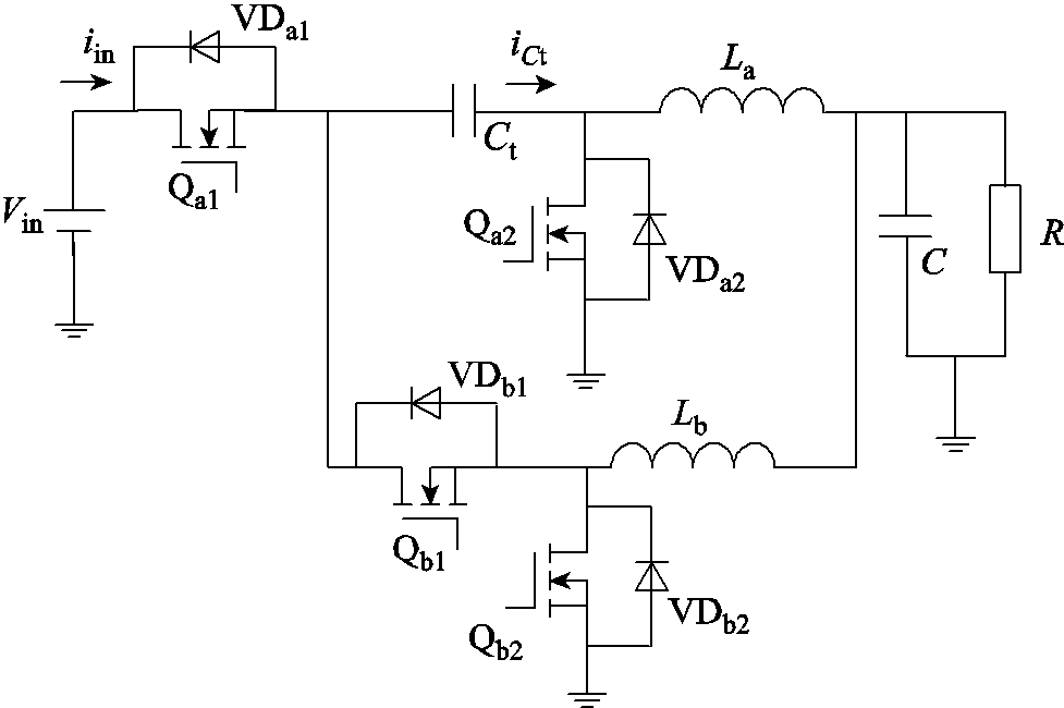
图1 串联电容降压变换器
Fig.1 Series-capacitor Buck converter
摘要 传统两相串联电容降压变换器具有自动相电流平衡、稳态开关电压应力小等优点,该文在传统两相串联电容降压变换器的基础上,增加两个电容和一个开关,提出一种改进型高转换比的两相串联电容变换器。该变换器具有传统两相串联电容降压变换器优点,同时还具有更高的电压转换比和更低的输出电流纹波,可以有效降低输入滤波电容值和变换器启动过程中开关的电压应力。该文在详细分析该变换器工作原理的基础上,搭建了110 W的实验样机,实验结果证明了理论分析的正确性。
关键词:DC-DC变换器 高转换比 串联电容 电压应力
Buck变换器因其拓扑结构简单、易于控制而被广泛应用于非隔离降压场合中[1-2]。近年来,微控制器、通信系统、数据中心、分布式储能等对高转换比降压变换器的需求迅速增加[3-5]。然而,对于传统Buck变换器,在高转换比应用中占空比会变得非常窄[6-7]。这导致变换器的导通损耗和开关损耗高、效率低[8-9]。同时变换器的输出电流纹波变大,稳定性也会变差。为了解决上述问题,国内外学者提出了许多提高变换器电压转换比的方法。其中使用两级变换器实现高电压转换比是最简单直接的方法[10-11],但是由于电路采用了两级结构,电路中的元件数量会增多,电路成本也会比单级变换器高[12],同时由于需要两级功率传输,变换器的整体效率会降低。
为了提高变换器的电压转换比,文献[13-15]提出了基于耦合电感的变换器。在这些变换器中有两个自由度,即占空比和耦合电感的匝数比。通过改变耦合电感的匝数比,可以很容易地获得高电压转换比。然而,耦合电感的漏感容易与开关寄生电容发生谐振从而在开关两端产生电压尖峰和振荡,这些电压尖峰会增大开关损耗,通常需要在这种变换器中添加额外的钳位电路[16-17]。
文献[18]提出了一种交错式降压变换器,可提高电压转换比、减小输出电流纹波。但是该变换器的电压转换比的提高效果并不明显。为了获得更高的降压比并拓展占空比,文献[19-21]提出了两相串联电容降压(Series Capacitor Buck, SC Buck)变换器,变换器的拓扑结构如图1所示。

图1 串联电容降压变换器
Fig.1 Series-capacitor Buck converter
图1中,Qa1、Qa2、Qb1以及Qb2为开关管,VDa1、VDa2、VDb1以及VDb2为开关管的反并联二极管。Ct为串联电容,C为输出滤波电容,La和Lb为输出滤波电感,R为负载电阻。Vin为输入电压,iin为输入电流,iCt为流入电容Ct的电流。与传统两相交错降压变换器相比,该变换器只增加了一个电容,电压转换比提高了1倍。并且对于数量一半以上的开关,电压应力降低了一半。此外,变换器输出电流纹波较小,同时具有自动平衡两相电流的能力[22]。值得注意的是,虽然SC Buck变换器由于加入了串联电容,稳态时开关的电压应力较小,但在启动过程中,因为在变换器开始工作之前,电路中串联电容器的电压为零,对于SC Buck变换器,一些在稳态时电压应力为Vin/2的开关在启动时的电压应力为Vin,所以在启动时开关的电压应力与传统的两相交错降压变换器相同。文献[23]所提出的变换器在SC Buck变换器的基础上添加了一个电容,使得变换器的电压转换比提高至Buck变换器的3倍,相比于SC Buck变换器提高了1.5倍,并且也能够有效降低稳态时开关的电压应力。但是这种变换器和SC Buck变换器一样,启动过程中电压应力较高,大小为Vin。
若能降低开关在启动过程中的电压应力,则变换器可以使用额定电压更低的开关。通常开关的额定电压越低其导通电阻也会更小,这会降低开关的损耗,有助于变换器效率的提升。文献[24]提出了一种基于SC Buck变换器的改进型拓扑结构,该变换器的开关在稳态和启动时具有相同的电压应力,均为Vin/2。但是这种变换器的电压转换比相比于SC Buck变换器并没有提高。
为了提高SC Buck变换器的电压转换比,消除启动电压应力问题,本文提出了一种改进型高转换比两相串联电容变换器。该变换器具有降压比高、输出电流纹波小、自动相电流平衡、输入滤波电容值小、稳态和启动时开关电压应力低等优点。
几种不同的高电压转换比变换器和所提出变换器的性能对比情况见表1。表中,D为占空比。
表1 不同高电压转换比变换器对比
Tab.1 Comparison of different high conversion ratio converters

参数变换器 文献[20]文献[24]文献[25]本文所提 电压转换比D/2D/2D/[2(1+D)]D/3 开关数量4485 二极管数量0000 电容数量1233 电感数量2222 最大开关电压应力VinVinVin2Vin/3 减小启动电压应力否是否是 开关频率/kHz1 00050100100
本文所提出变换器拓扑结构如图2所示。与图1所示SC Buck变换器相比,增加了一个开关Qc,输入端增加了两个电容C1和C2。图2中C3为串联电容,VDc为Qc的反并联二极管,其余物理量的含义与图1中相同。
图3给出了所提出变换器在稳态下的工作波形,T为开关周期。占空比D为开关Qa1、Qb1、Qc的导通时间与开关周期T的比值;D不能超过50%,否则,当Qa1和Qb1同时开通时,电容C1会发生短路。VGS为开关管的驱动信号。Vds为开关管的漏极和源极之间的电压。电流iin为变换器的输入电流,iLa和iLb为流过电感La和Lb的电流。电流iC1、iC2以及iC3分别为流入电容C1、C2及C3的电流。电压vC1、vC2以及vC3分别为电容C1、C2以及C3上的电压。Vin为变换器的输入电压,Io为变换器输出电流的平均值。
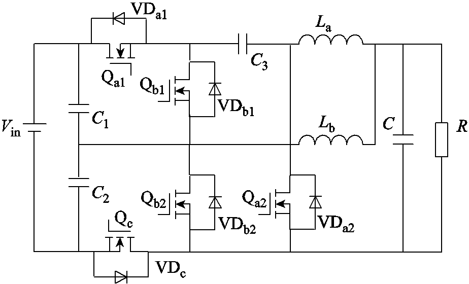
图2 所提变换器拓扑结构
Fig.2 The proposed converter
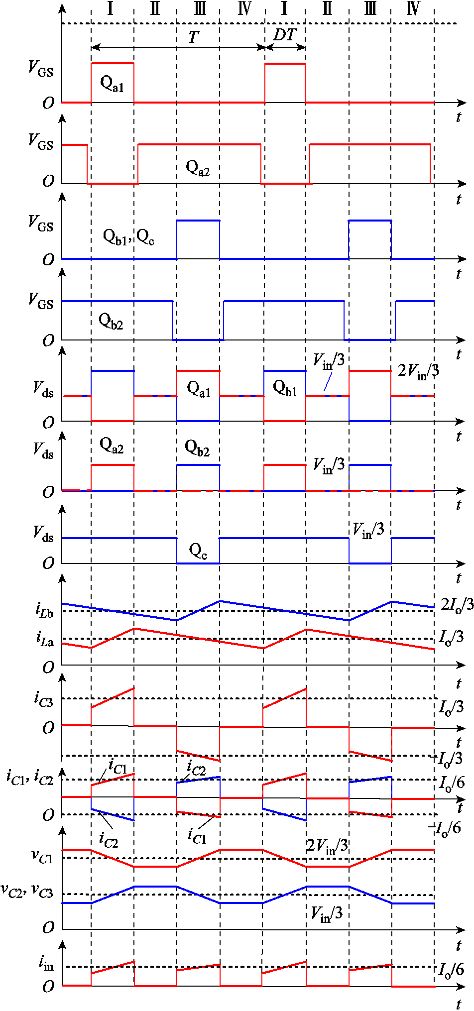
图3 所提出变换器的主要波形
Fig.3 Key waveforms of the proposed converter
为了便于分析说明,这里作了几个假设。
1)由于电容器C1、C2、C3的值足够大,所以假设稳态时电容器上的电压是恒定的。同时,C1=C2=C3/2。
2)所有开关都是理想的,不考虑开关的寄生电容和导通电阻。
3)电感La和Lb的值足够大,变换器工作在连续导通模式(Continous Conduction Mode, CCM)下。同时,La=Lb=L。
该变换器在一个开关周期内共有四种工作模式,不同工作模式下的变换器等效电路如图4所示。为便于后续说明,假设电流iLa流过的路径用A相表示,电流iLb流过的路径用B相表示。

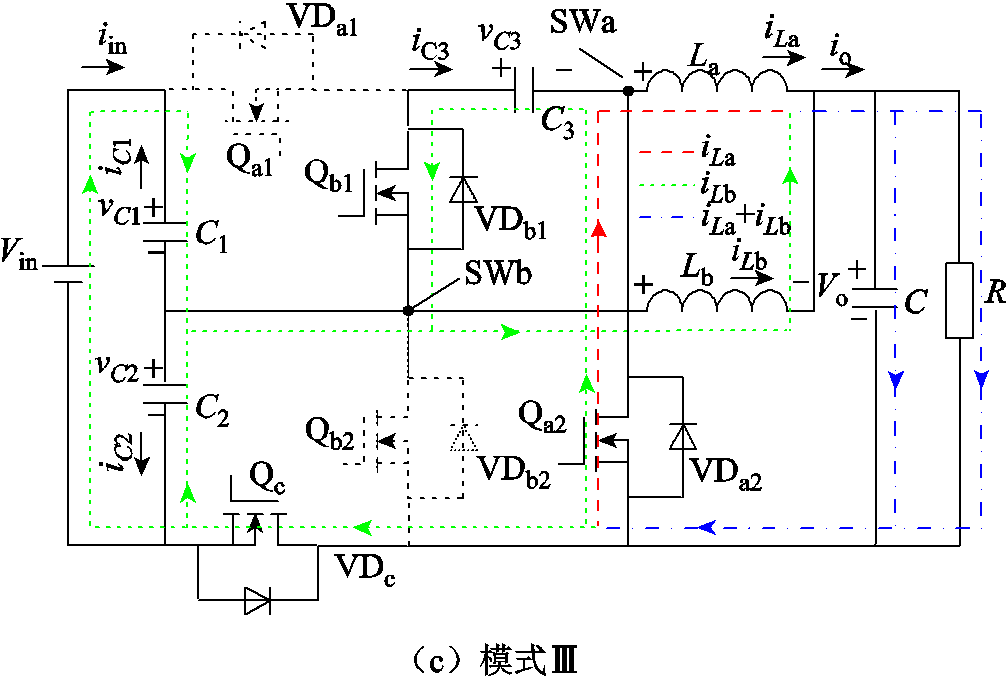
图4 所提出变换器在不同模式下的等效电路
Fig.4 Equivalent circuits of the proposed converter in different modes
模式Ⅰ[t0, t1):开关Qa1、Qb2开通,Qb1、Qa2、Qc关断,A相工作在充电模式,B相工作在续流模式,等效电路如图4a所示。电容器C1放电,电容器C2和C3充电。流过电容C1和C2的电流是流过电容C3的电流的一半。
 (1)
(1)
电感La中的电流线性增大,电感Lb中的电流线性减小。此模式下电感La两端电压为
 (2)
(2)
式中,VC1和VC3分别为稳态时电容C1和电容C3两端的平均电压;Vo为变换器的输出电压。
此模式下电感Lb两端电压为
 (3)
(3)
模式Ⅱ[t1, t2):开关Qa2、Qb2开通,Qa1、Qb1、Qc关断,A、B相均为续流模式,等效电路如图4b所示。此模式下电感La和Lb两端电压为
 (4)
(4)
模式Ⅲ[t2, t3):开关Qb1、Qa2、Qc开通,Qa1、Qb2关断,B相为充电模式,A相为续流模式,等效电路如图4c所示。电容器C1充电,电容器C2和C3放电。电感Lb中的电流线性增大,电感La中的电流线性减小。此模式下电感Lb两端电压为
 (5)
(5)
在此模式下,电容C2的电压和电容C3的电压相等。此模式下电感La两端电压为
 (6)
(6)
模式Ⅳ[t3, t4]:该模式工作过程与模式Ⅱ完全相同。开关Qa2、Qb2开通,Qa1、Qb1、Qc关断,A、B两相均为续流模式,等效电路如图4b所示。
利用电感伏秒平衡原理分析,根据式(2)~式(6),可得
 (7)
(7)
 (8)
(8)
根据模式Ⅲ,电容C1和C2的电压之和等于输入电压Vin,电容C2和C3电压相等。
 (9)
(9)
 (10)
(10)
式中,VC2为稳态下电容C2两端的平均电压。
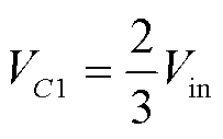
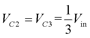
由式(7)~式(10)可知,三个电容器稳态时的电压平均值为
 (11)
(11)
 (12)
(12)
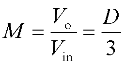
由式(7)、式(8)、式(11)、式(12)可得变换器的电压转换比为
 (13)
(13)
不同拓扑的电压转换比如图5所示,从图中可以看出,本文提出的变换器具有较高的电压转换比。
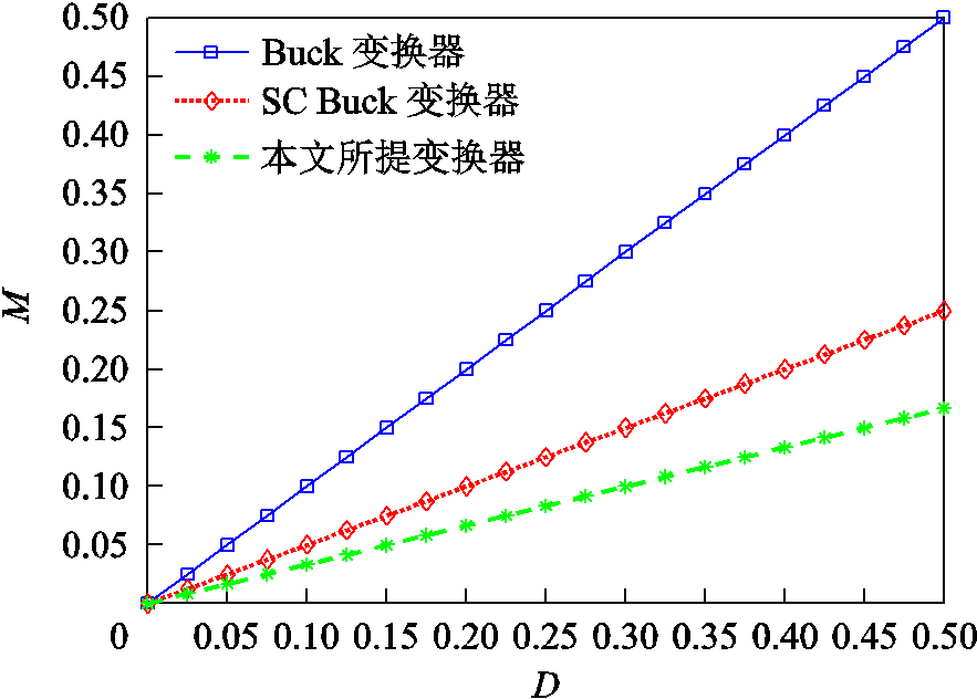
图5 不同拓扑的电压转换比对比
Fig.5 Comparison of voltage conversion ratio of different topologies
根据模式Ⅰ分析,可以得到电感La中的电流纹波为
 (14)
(14)
电感Lb中的电流纹波为
 (15)
(15)
根据式(11)、式(12)可以进一步简化电感电流纹波方程为
 (16)
(16)
输出电流纹波可以通过在DT时段内叠加两个电感电流纹波得到,即
 (17)
(17)
不同拓扑的输出电流纹波对比如图6所示。由此可见,所提变换器具有较低的输出电流纹波。
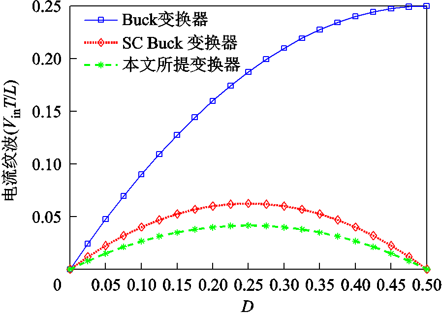
图6 不同拓扑的输出电流纹波对比
Fig.6 Comparison of output current ripple of different topologies
变换器的输出电流平均值等于两相电流之和,即
 (18)
(18)
式中,ILa和ILb为电感La和Lb上电流的平均值。
在模式Ⅰ,电容C3的充电电流是流过电感La的电流。此外,因为电容C1和电容C2的容值是电容C3的一半,所以在模式Ⅲ电容C3放电电流是电感Lb电流的一半,另一半电流由C1和C2承担。结合模态分析对电容C3使用安秒平衡原理得
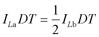 (19)
(19)
由式(18)、式(19)可得两相电流的平均值为
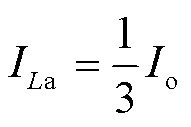 (20)
(20)
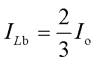 (21)
(21)
本文所提变换器的一个特点是相电流自动平衡。这一特性对于高频下的电流传感和重构具有重要意义。此外,消除了平衡两相电流的控制回路,大大地简化了变换器的控制方案,有利于变换器在更高的频率下工作。下面结合图4介绍相电流自动平衡原理。变换器中的电容C1、C2和C3的平均电压在稳态下是恒定的,但是如果A相电流增加并且大于Io/3,则电感电流分配发生变化会引起电容电压的平均值发生变化。电容C2和C3的平均电压会增加,电容C1的平均电压会降低,这会导致SWa节点上的电压降低,SWb节点上的电压增加,电容电压的变化反过来又会影响电感电流的分配,由于SWa节点上的电压降低,SWb节点上的电压增加,使得A相电流减小,B相电流相应增大。经过不断的调节,流过两个电感的电流会趋于稳定,最终稳定在Io/3和2Io/3;反之,当B相电流增大时,两相电流调节过程类似。
与两相电感电流自动平衡原理类似,当电容C1、C2、C3的电压不平衡时,电容电压会自动调整到平衡状态。以电容C3为例,当电容C3的电压大于Vin/3时,SWa点的电压会降低。这时A相电流会减小,电容C3的充电电流会减小,所以电容C3的电压也会减小。其他电容的电压调节过程与C3类似,在此不再赘述。
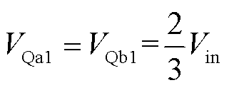
根据图4,可以得到各个开关在稳态下的电压应力为
 (22)
(22)
 (23)
(23)
可以看出,所提出变换器中开关电压应力都很低,最大电压应力仅为2Vin/3。这使得变换器可以选用较低额定电压的开关,从而有利于降低导通损耗和开关损耗。
对于图1所示的SC Buck变换器,在启动时刻串联电容Ct上的电压为零。开关Qa1和Qa2稳态时的电压应力为Vin/2,启动时的电压应力为Vin。而对于本文所提变换器,变换器启动前,在输入电压Vin的作用下,电容C1和电容C2上的电压均为Vin/2。启动前电容C3的电压为零。结合图4中各模式的等效电路可以发现,所有开关在启动时刻的电压应力为Vin/2。因此所提变换器具有开关启动时电压应力低的优点。
该变换器还可以反向工作在Boost升压模式下。由于电容C1和C2的存在,当变换器工作在升压模式时,可以实现双路输出,电容C1和电容C2可分别作为两路输出的输出滤波电容。并且根据前面分析的电容电压自动平衡,两路输出电压可以实现自动平衡。这种特性是SC Buck变换器不具备的。
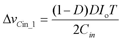
对于图1中的SC Buck变换器,其输入电流和流过电容Ct的电流如图7所示。在文献[20]中对SC Buck变换器的工作模式进行了详细的分析,这里不再赘述。在实际应用中,由于输入电流不连续,变换器通常需要输入滤波电容Cin。根据图7,可以计算出SC Buck变换器输入滤波电容的电压纹波为
 (24)
(24)
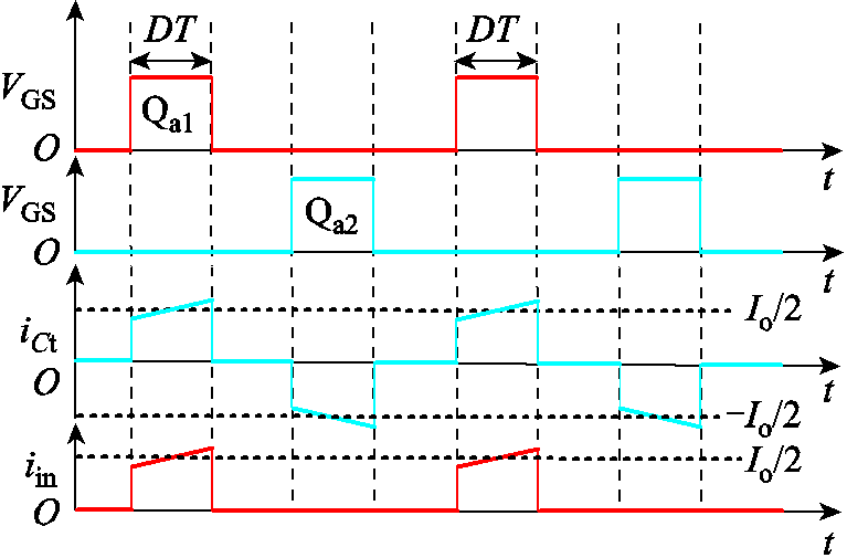
图7 SC Buck变换器的输入和串联电容电流
Fig.7 Input and capacitor currents of SC Buck converter
如图4所示,在模式Ⅰ和模式Ⅲ中,电容C1、C2和C3参与了能量传递。变换器输入端的电源和电容C1、C2、C3一起为电感提供能量。在模式Ⅰ中,存在如下关系
 (25)
(25)
在模式Ⅲ中,电流关系为
 (26)
(26)
iC1、iC2和iin的波形如图3所示。与SC Buck变换器相比,该变换器的输入电流频率更高、幅值更小。根据图3,可以计算出输入滤波电容的电压纹波为
 (27)
(27)
文献[24]中提出的变换器输入滤波电容电压纹波为
 (28)
(28)
当输入滤波电容的电压纹波相同时,不同拓扑所需要的输入滤波电容对比如图8所示。与其他两种变换器相比,本文提出的变换器的输入滤波电容最小。虽然与SC Buck变换器相比,所提出的变换器增加了两个电容,但其输入滤波电容较小。此外,由于所提出的变换器的输出电流纹波小于SC Buck变换器,因此所需的输出滤波电容也更小。因此,所提出的变换器的整体电容体积更小。
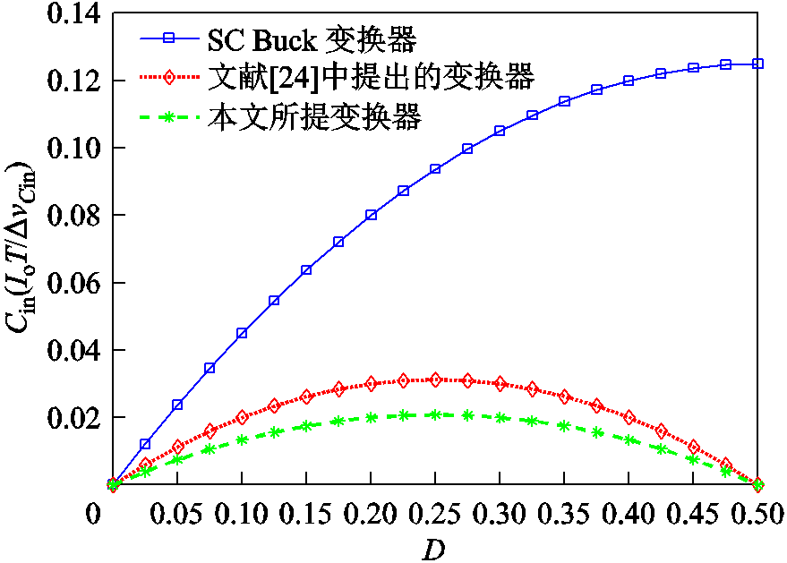
图8 不同拓扑的输入滤波电容对比
Fig. 8 Comparison of the input filter capacitance of different topologies
为了验证所提出变换器的工作性能,搭建了110 W的实验样机,样机如图9所示。样机的参数和所用器件型号见表2。

图9 实验样机照片
Fig.9 The photo of experimental prototype
表2 变换器参数和器件型号
Tab.2 Converter parameters and device models
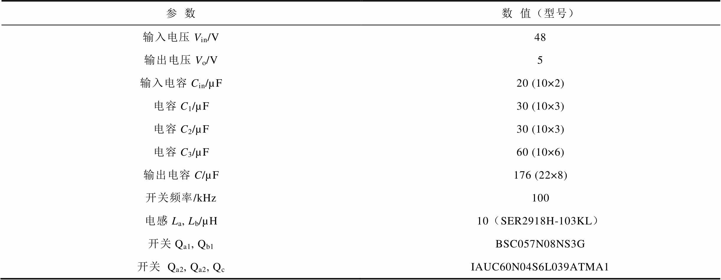
参数数值(型号) 输入电压Vin/V输出电压Vo/V485 输入电容Cin/µF20 (10×2) 电容C1/µF30 (10×3) 电容C2/µF30 (10×3) 电容C3/µF60 (10×6) 输出电容C/µF176 (22×8) 开关频率/kHz100 电感La, Lb/µH10(SER2918H-103KL) 开关Qa1, Qb1BSC057N08NS3G 开关Qa2,Qa2,QcIAUC60N04S6L039ATMA1
电感电流iLa和iLb、输出电流io、输出电压Vo的波形如图10所示。输入电压Vin=48 V,输出电压Vo=5 V,输出电压纹波小于10 mV。输出电流Io=22 A,纹波约为1.9 A。此外可以看出,iLa和iLb的纹波是交错的。电流iLa的平均值为Io/3,电流iLb的平均值为2Io/3,电流iLa和iLb的纹波约为3.5 A。两相交错并联输出结构大大降低了输出电流纹波,同时减小了开关和电感的电流应力。并且相比于传统SC Buck变换器,所提出变换器输出电流纹波更小。由于输出滤波电容C对电流纹波有滤波作用,为了避免滤波电容的干扰,本文所提到的输出电流是指流经输出滤波电容之前的电流。
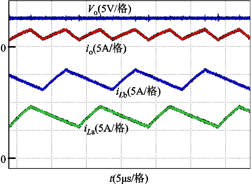
图10 iLa,iLb, io和Vo的波形
Fig.10 The waveforms of iLa,iLb, io and Vo
稳态下开关Qa1和Qb1的电压应力如图11a所示,稳态时Qa2、Qb2和Qc的电压应力如图11b所示。可以看出,Qa1和Qb1的电压应力为2Vin/3,Qa2、Qb2和Qc的电压应力为Vin/3。所提出变换器在稳态时开关的电压应力整体上低于SC Buck变换器,并且通过图11可以发现此时占空比在30%左右。相比之下,传统SC Buck变换器在达到相同降压比时占空比仅有20%左右,因此所提出变换器具有更高的电压转换比。
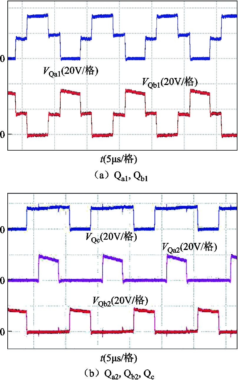
图11 开关的电压应力
Fig.11 The voltage stress of different switches
电容C1、C2和C3的电压波形如图12所示。电容C1的平均电压为2Vin/3,即32 V。电容C2和C3的平均电压为Vin/3,即16 V。实验结果与理论分析一致。
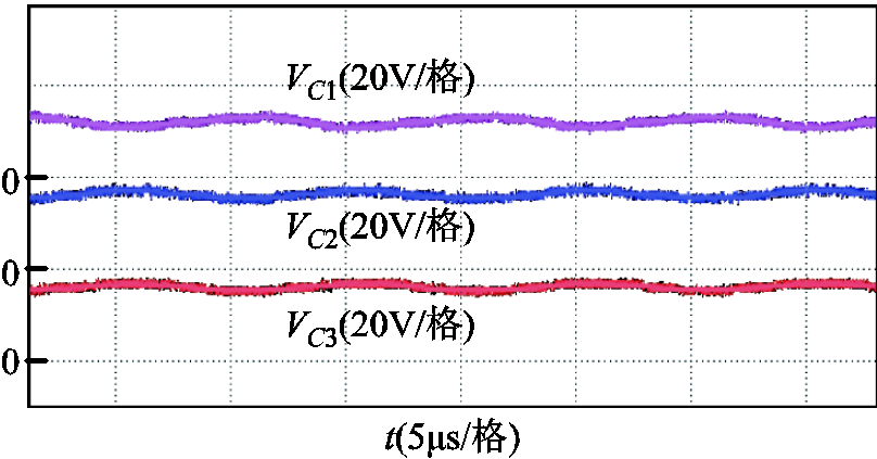
图12 电容C1, C2和C3上的电压波形
Fig.12 The voltage waveforms of capacitors C1, C2 and C3
变换器启动过程中开关的电压应力如图13和图14所示。变换器启动前,Qa1和Qc的电压应力为Vin/2,即24 V,其他开关的电压应力为0 V。通过实验波形可以看出,在变换器启动过程中Qa1和Qb1的电压应力分别由启动前的24 V和0 V逐渐稳定在稳态时的2Vin/3,即32 V。开关Qa2、Qb2和Qc在变换器启动过程中电压应力分别由启动前的0 V、0V以及24 V逐渐稳定在稳态时的Vin/3,即16 V。在启动前和启动过程中,所提出变换器的开关电压应力均小于SC Buck变换器。
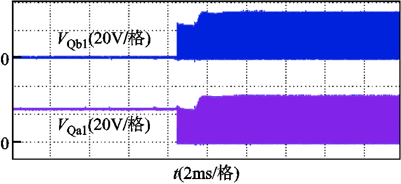
图13 变换器启动阶段开关Qa1和Qb1的电压应力
Fig.13 The voltage stress of Qa1 and Qb1 during start-up
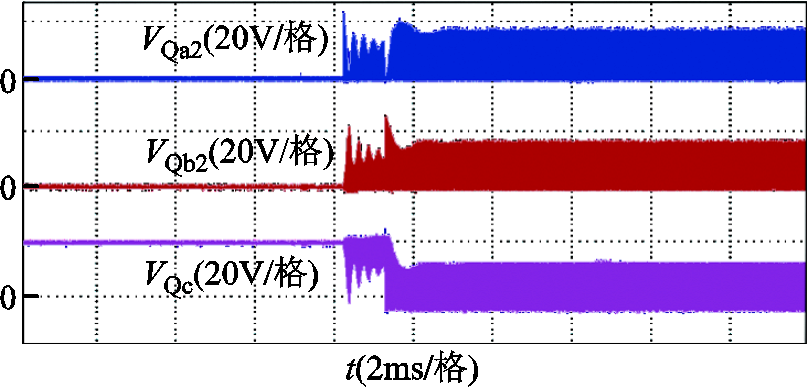
图14 变换器启动阶段开关Qa2, Qb2和Qc的电压应力
Fig.14 The voltage stress of Qa2, Qb2 and Qc during start-up
系统损耗主要包括磁性元件损耗和开关损耗,其他损耗占比很小,可以忽略不计。对各部分损耗进行计算,绘制出了变换器在满载情况下各部分的损耗分布,如图15所示。图15中开关过程损耗是指开通损耗和关断损耗之和。从图中可以看出,主要的损耗是磁性元件损耗和开关导通损耗。
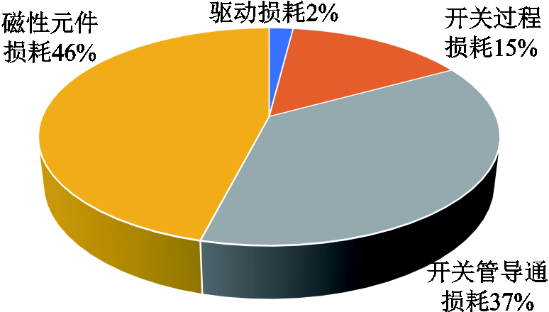
图15 所提出变换器损耗分布
Fig.15 Pie chart of loss distribution of the proposed converter
所提出变换器的效率曲线如图16所示,从图中可以看出,随着功率的增大,变换器效率先增大后减小。在满载的60%左右达到效率峰值,此时效率可达97.3%,满载时效率为95.9%。
本文提出了一种改进型高转换比两相串联电容变换器。该变换器的电压转换比是SC Buck变换器的1.5倍,是传统Buck变换器的3倍。变换器采用两相交错输出结构,输出电流纹波较低。与SC Buck变换器相比,当输入滤波电容的电压纹波相同时,所需的输入滤波电容更小。此外该变换器在稳态工作和启动时电压应力低,具有自动相电流平衡能力,可以反向工作并且在反向工作时具有两相电压自动平衡的优点。在详细分析变换器工作原理和工作性能的基础上,设计了实验样机,实验结果验证了理论分析的正确性和可行性,满载时效率为95.9%。
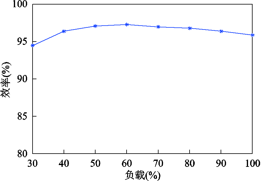
图16 所提出变换器效率曲线
Fig.16 Efficiency curves of the proposed converter
参考文献
[1] Liu Xinjian, Calhoun B H, Li Shuo. A sub-nW 93% peak efficiency Buck converter with wide dynamic range, fast DVFS, and asynchronous load-transient control[J]. IEEE Journal of Solid-State Circuits, 2022, 57(7): 2054-2067.
[2] Do H-L. Zero-voltage-switching synchronous buck converter with a coupled inductor[J]. IEEE Transactions on Industrial Electronics, 2011, 58(8): 3440-3447.
[3] Lee S S. Step-down converter with efficient ZVS operation with load variation[J]. IEEE Transactions on Industrial Electronics, 2014, 61(1): 591-597.
[4] Yau Y T, Jiang W Z, Hwu K I. Ultrahigh step-down converter with wide input voltage range based on topology exchange[J]. IEEE Transactions on Power Electronics, 2017, 32(7): 5341-5364.
[5] 肖思昌, 陈洪胜, 陈锦立, 等. 分布式储能中大降压比Buck变换器的优化设计[J]. 电源学报, 2023, 21(3): 20-26. Xiao Sichang, Chen Hongsheng, Chen Jinli, et al. Optimal design of Buck converter with large step-down ratio for distributed energy storage[J]. Journal of Power Supply, 2023, 21(3): 20-26.
[6] He Liangzong, Chen Jiazhe, Xu Xinyong, et al. Soft-switching voltage-demultiplier-cell-based high step-down DC-DC converter[J]. IEEE Transactions on Power Electronics, 2019, 34(10): 9828-9843.
[7] 刘俊峰, 胡仁俊, 曾君. 一种非隔离交错工作的高降压比DC-DC功率变换器[J]. 电工技术学报, 2018, 33(20): 4763-4770. Liu Junfeng, Hu Renjun, Zeng Jun. A non-isolated interleaved step-down DC-DC power converter with high ratio[J]. Transactions of China Electrotechnical Society, 2018, 33(20): 4763-4770.
[8] Marvi F, Adib E, Farzanehfard H. Efficient ZVS synchronous Buck converter with extended duty cycle and low-current ripple[J]. IEEE Transactions on Industrial Electronics, 2016, 63(9): 5403-5409.
[9] Liu Jianhong, Tseng C W, Chu C-C. High step-down conversion ratios of DC-DC converters under triple PWM control schemes[C]//IEEE Industry Applications Society Annual Meeting, Vancouver, BC, Canada, 2022: 1-8.
[10] Xie Xiaogao, Qian Zhaoming. A new two-stage Buck converter for voltage regulators[C]//IEEE Power Electronics Specialists Conference, Rhodes, Greece, 2008: 1580-1584.
[11] 梅杨, 陈丽莎, 黄伟超, 等. 级联式双向DC-DC变换器的优化控制方法[J]. 电工技术学报, 2017, 32(19): 153-159. Mei Yang, Chen Lisha, Huang Weichao, et al. Optimized control method of cascaded Bi-directional DC-DC converters[J]. Transactions of China Electrotechnical Society, 2017, 32(19): 153-159.
[12] Hwu K I, Jiang W Z, Wu P Y. An expandable two-phase interleaved ultrahigh step-down converter with automatic current balance[J]. IEEE Transactions on Power Electronics, 2017, 32(12): 9223-9237.
[13] Grant D A, Darroman Y, Suter J. Synthesis of tapped-inductor switched-mode converters[J]. IEEE Transactions on Power Electronics, 2007, 22(5): 1964-1969.
[14] Yao Kaiwei, Ye Mao, Xu Ming, et al. Tapped-inductor buck converter for high-step-down DC-DC conversion[J]. IEEE Transactions on Power Electronics, 2005, 20(4): 775-780.
[15] Modeer T, Norrga S, Nee H P. High-voltage tapped-inductor Buck converter utilizing an autonomous high-side switch[J]. IEEE Transactions on Industrial Electronics, 2015, 62(5): 2868-2878.
[16] Hajiheidari M, Farzanehfard H, Adib E. High-step-down DC-DC converter with continuous output current using coupled-inductors[J] IEEE Transactions on Power Electronics, 2019, 34(11): 10936-10944.
[17] Xu Peng, Wei Jia, Lee F C. The active-clamp couple-buck converter-a novel high efficiency voltage regulator modules[C]//Sixteenth Annual IEEE Applied Power Electronics Conference and Exposition, Anaheim, CA, USA,2002: 252-257.
[18] Esteki M, Poorali B, Adib E, et al. Interleaved Buck converter with continuous input current, extremely low output current ripple, low switching losses, and improved step-down conversion ratio[J]. IEEE Transactions on Industrial Electronics, 2015, 62(8): 4769-4776.
[19] Shenoy P S, Lazaro O, Ramani R, et al. A 5 MHz, 12 V, 10 A, monolithically integrated two-phase series capacitor Buck converter[C]// IEEE Applied Power Electronics Conference and Exposition, Long Beach, CA, USA, 2016: 66-72.
[20] Shenoy P S, Amaro M, Morroni J, et al. Comparison of a Buck converter and a series capacitor Buck converter for high-frequency, high-conversion-ratio voltage regulators[J]. IEEE Transactions on Power Electronics, 2016, 31(10): 7006-7015.
[21] Lee I O, Cho S Y, Moon G W. Interleaved Buck converter having low switching losses and improved step-down conversion ratio[J]. IEEE Transactions on Power Electronics, 2012, 27(8): 3664-3675.
[22] Shenoy P S, Lazaro O, Amaro Mi, et al. Automatic current sharing mechanism in the series capacitor Buck converter[C]//IEEE Energy Conversion Congress and Exposition, Montreal, QC, Canada, 2015: 2003-2009.
[23] Kirshenboim O, Peretz M M. High-efficiency nonisolated converter with very high step-down conversion ratio[J]. IEEE Transactions on Power Electronics, 2017, 32(5): 3683-3690.
[24] Kim K, Cha H, Park S, et al. A modified series-capacitor high conversion ratio DC-DC converter eliminating start-up voltage stress problem[J]. IEEE Transactions on Power Electronics, 2018, 33(1): 8-12.
[25] Wang Yijie, Zhang Jinfeng, Guan Yueshi, et al. Analysis and design of a two-phase series capacitor dual-path hybrid DC-DC converter[J]. IEEE Transactions on Power Electronics, 2022, 37(8): 9492-9502.
Abstract For traditional buck converter, the duty cycle is narrow in high conversion ratio applications. This results in high losses and low efficiency of the converter. At the same time, the output current ripple of the converter becomes larger, and the stability will also deteriorate.In order to solve the above problems, scholars have proposed many methods to improve the voltage conversion ratio of converters.Among them, SC (Series Capacitor) Buck converter is a commonly used high voltage conversion ratio converter, and has the advantage of low voltage stress of switches in steady state. However, the voltage stress of the switches is high during converter start-up.This paper proposes an improved two-phase series-capacitor converter with high conversion ratio.While inheriting the advantages of the SC Buck converter, the converter has a higher voltage conversion ratio and lower output current ripple, and can effectively reduce the input filter capacitor value and the voltage stress of the switches during converter start-up.
The proposed converter adds two capacitors and a switch to the SC Buck converter, which has the following advantages. First, compared to the SC Buck converter, the voltage distribution across the capacitor is changed, which results in a higher voltage conversion ratio and lower switching voltage stress in steady state.Second, the voltage across the inductor of the proposed converter is lower than that of the SC Buck converter, so the inductor current ripple and output current ripple of the proposed converter are smaller. Third, in the steady state, the voltage on the series capacitor satisfies the ampere-second balance, which provides a balanced loop between the two phases. This current sharing mechanism is inherent to the topology and acts like a damped harmonic oscillator. Fourth, the capacitor on the input side of the proposed converter is pre-charged before the converter starts, which reduces the voltage stress of the switches during start-up.Therefore, the proposed converter can use switches with lower voltage rating, which helps to reduce the loss of the switches and improve the efficiency of the converter. Fifth, compared to SC Buck converter, the input voltage ripple of the proposed converter is smaller when the input filter capacitance is the same, so when the input voltage ripple is the same, the input filter capacitance required by the proposed converter is smaller.
A 110 W experimental prototype was built and the characteristics of the converter were verified.The experimental results show that when the converter achieves 48~5 V, the duty cycle is about 30%.In contrast, the SC Buck converter has a duty cycle of only about 20% when the same step-down ratio is reached, proving that the proposed converter has a higher voltage conversion ratio.In steady state, the voltage stress of two switches is 32 V, and the voltage stress of three switches is 16 V. The voltage stress of all switches is less than the input voltage.Before the converter starts, the voltage stress of two switches is 24 V, the voltage stress of three switches is 0 V. The maximum voltage stress of the switches before the converter starts is only half of the input voltage. And the maximum voltage stress of the switches during converter start-up is 32 V, which is less than the input voltage.The single-phase inductor current ripple is 3.5 A, and the current ripple after the superposition of the two phases is about 1.9 A. The two-phase interleaved parallel output structure greatly reduces the output current ripple.
According to theoretical analysis and experimental verification, the following conclusions can be drawn: (1) Compared with SC Buck converter, the proposed converter has a higher voltage conversion ratioand lower output current ripple. (2) Compared with the SC Buck converter, the voltage stress of the switches of the proposed converter in the steady state is lower and the voltage stress of the switches during start-up is reduced. (3) The proposed converter has automatic phase current balancing capability. It can eliminate a control loop that requires high performance circuits to balance phase currents. (4) Compared with the SC Buck converter, when the voltage ripple of the input filter capacitor is the same, the required input filter capacitance is smaller.
keywords: DC-DC converter, high conversion ratio (HCR), series-capacitor, voltage stress
DOI: 10.19595/j.cnki.1000-6753.tces.L10044
中图分类号:TM61
国家自然科学基金资助项目(51977045)。
收稿日期 2023-01-13
改稿日期 2023-02-22
刘桂花 女,1976年生,博士,副教授,研究方向为高频开关电源、光伏并网发电技术。E-mail: liuguihua@hit.edu.cn(通信作者)
王博鑫 男,1999年生,硕士研究生,研究方向为高频开关电源。E-mail: 21S006039@stu.hit.edu.cn
(编辑 陈诚)