图1 电压空间矢量平面
Fig.1 Voltage space vector plane diagram
摘要 针对传统单传感器直流母线采样系统中相电流重构盲区问题,该文分析传统空间矢量脉冲宽度调制(SVPWM)技术的电流采样方法和重构盲区产生的原因,精确地划分电压空间矢量平面的各个区域。提出一种互补非零矢量脉宽调制(CNSVPWM)方法,通过在中调制区添加互补非零矢量来延长电流采样窗口的时间,满足直流母线电流最小采样时间要求,消除了电流重构盲区,拓展了电机的运行范围。仿真及实验结果表明,采用CNSVPWM方法电流总谐波畸变率(THD)低于6.15 %,重构误差低于3 %,电机在动态工况下运行正常。
关键词:直流母线采样 单传感器 空间矢量脉冲宽度调制(SVPWM) 相电流重构
交流电机因其高可靠性、高功率密度、高控制精度等优点广泛应用于工业生产、交通运输、军用航天等领域[1-3]。传统的交流伺服控制系统中,电机相电流是矢量控制系统的核心参数,相电流检测对提高控制系统性能具有重要意义[4-5]。传统的矢量控制系统至少需要两个电流传感器来实现电流的精准采集,达到闭环控制。多个传感器既增加系统成本,又因传感器之间的不一致性影响电机控制性能[6-7]。单电流传感器技术(Single Current Sensor Technology, SCST)通过直流母线侧电流的分时采集,实现了单传感器相电流采样,在降低系统成本的同时避免了多个传感器参数不一致对系统性能造成的影响,成为电驱动控制系统领域的研究热点[8-9]。单传感器相电流重构技术的主要难点在于,受最小采样时间的限制,在电压矢量空间的低调制区和扇区边界会不可避免地出现电流重构盲区,无法进行可靠的相电流采样[10-14]。
针对电流重构盲区,一些研究方法通过修改脉冲宽度调制(Pulse Width Modulation, PWM)方式,增大电流采样窗口来消除重构盲区[15-19]。文献[20]提出了一种混合脉宽调制方法,通过在每个PWM周期的开始和中间时刻插入测量矢量,获得短暂的采样窗口,实现不可观测区的相电流重构。文献[21]采用三态脉宽调制技术,使用了三个相邻的开关状态来合成参考电压,在一定程度上缩小了电流重构盲区。文献[22-23]提出开关状态移相(Switching State Phase Shift, SSPS)脉宽调制算法,利用PWM波形的移相,增加电流观测窗口的时长,扩大了相电流重构范围,降低了电流谐波。文献[24]通过插入测量和补偿矢量提出了采样电压空间矢量脉宽调制(Sampling voltage Space Vector Pulse Width Modu- lation, SSVPWM)方法,减少了采样点的更新频率,避免了电流振荡引起的采样误差,实现相电流重构。文献[25]采用永磁同步电机无位置传感器电流预测法,分析了引入高频电压信号导致的重构误差,利用固定采样点预测d-q轴电流,实现了非观测区的部分电流检测。文献[26]对逆变器的死区效应、开关延时、通断损耗进行分析,在每个开关脉冲中进行补偿,保证了输出电压的准确性,降低了电流谐波。
针对单传感器相电流重构盲区问题,本文提出了一种互补非零空间矢量脉宽调制(Complementary Non-zero Space Vector Pulse Width Modulation, CNSVPWM)方法,通过划分调制区域,定义直流母线电流的最小采样时间,在空间电压矢量平面的中调制盲区插入互补非零矢量,增大电流采样窗口,实现了中调制盲区的电流采样和重构。
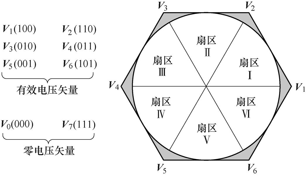
SVPWM控制是一种通过逆变器使电机的磁链生成圆形的旋转磁场以产生恒定电磁转矩的控制方法。逆变电路三相桥臂的开关状态均以Sx(x=A, B, C)表示,Sx=1为上桥臂导通,下桥臂关断;反之,用Sx=0表示。对逆变器三相开关的导通状态进行组合产生八种电压矢量,分别为:V1(100)、V2(110)、V3(010)、V4(011)、V5(001)、V6(101) 6个有效电压矢量以及V0(000)和V7(111)2个零电压矢量。六种有效电压矢量将电压空间平面划分为对称的6个扇区,电压空间矢量平面如图1所示。
图1 电压空间矢量平面
Fig.1 Voltage space vector plane diagram
在交流电机驱动系统中,每个控制周期内至少需要获取两相电流信息,才能完成电机的闭环控制。单传感器相电流重构方法中,将电流传感器安装在直流母线侧。通过每个PWM周期内两个不同有效矢量的作用对母线电流进行采样,得到相电流信息。
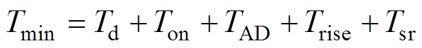
根据开关状态的不同,直流母线电流也会随之变化。以V100和V110为例,当V100作用时,直流母线电流idc=ia;当V110作用时,直流母线电流idc=-ic,逆变器的导通状态如图2所示。
由基尔霍夫电流定律计算得出三相电流为
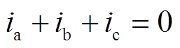 (1)
(1)
不同电压矢量作用时,直流母线电流与相电流的对应关系见表1。
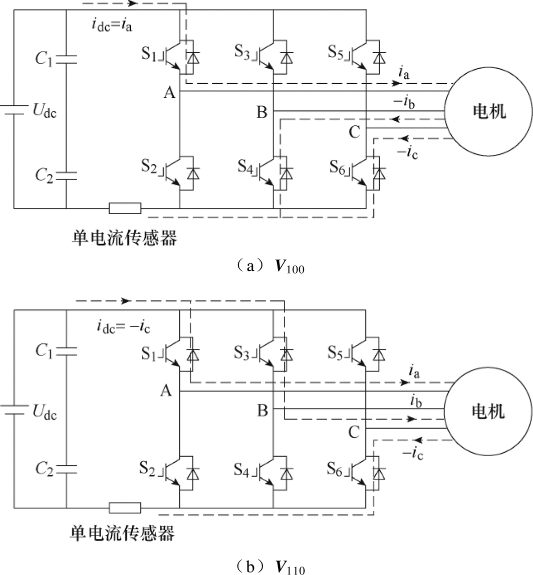
图2 电压矢量V100和V110作用时直流母线电流
Fig.2 DC bus current under voltage vector V100 and V110
表1 各扇区母线电流与开关状态的关系
Tab.1 DC bus current and switching state of each sector
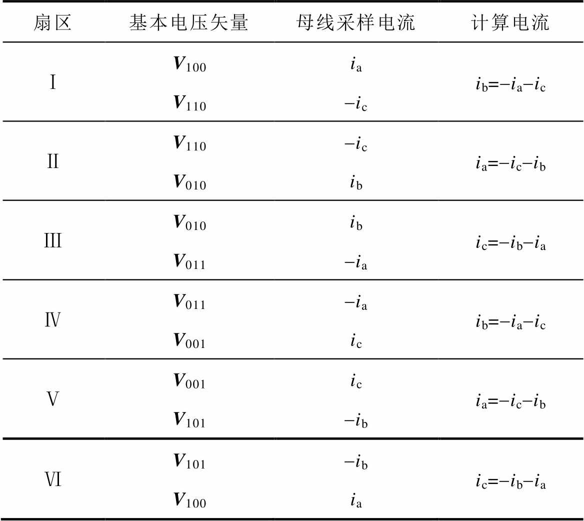
扇区基本电压矢量母线采样电流计算电流 ⅠV100V110ia-icib=-ia-ic ⅡV110V010-icibia=-ic-ib ⅢV010V011ib-iaic=-ib-ia ⅣV011V001-iaicib=-ia-ic ⅤV001V101ic-ibia=-ic-ib ⅥV101V100-ibiaic=-ib-ia
在实际电路中,由于逆变器中开关器件的响应特性,直流母线电流需要一段时间才能达到稳定状态,导致电流采样不能瞬时完成,理想电流信号和实际电流信号对比如图3所示。
直流母线电流达到稳定状态的时间中,Td是为了避免逆变器上下桥臂发生导通的死区延迟时间,Ton为功率开关器件的导通时间,TAD为模数转换所需的延时时间,Trise和Tsr分别为电流突变上升时间和电流达到稳态的振荡时间。为了满足直流母线电流采样要求,定义电流采样所需的最小时间Tmin为
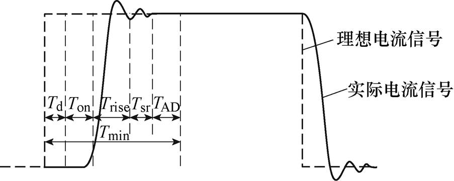
图3 理想电流信号和实际电流信号对比
Fig.3 Comparison diagram of ideal current signal and actual current signal
 (2)
(2)
电流采样窗口如图4所示,有效矢量V110作用下采样窗口时间Tsp<Tmin,无法保证电流-ic被准确采集。
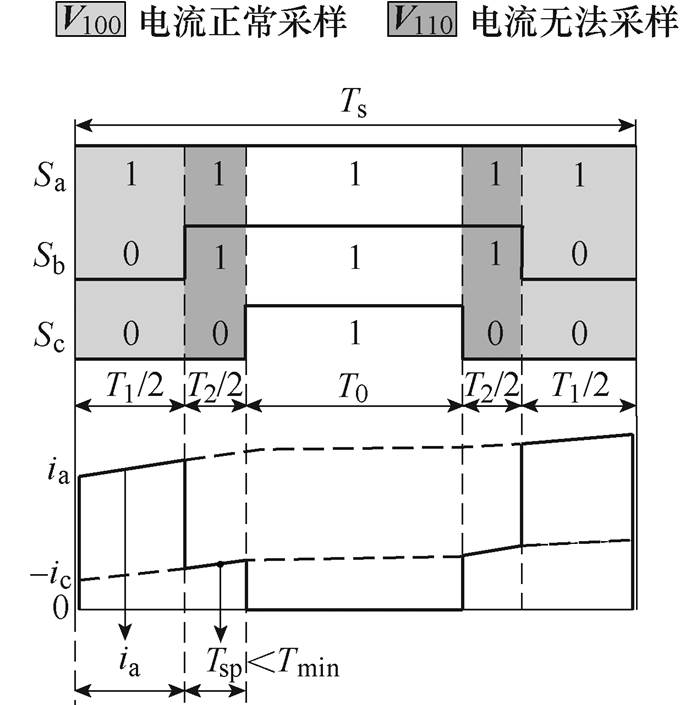
图4 电流采样窗口
Fig.4 Current sampling window
为了使采样窗口时长满足Tmin,对传统SVPWM方法下参考电压矢量及作用时间进行分析,得
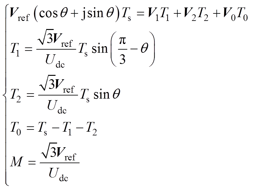 (3)
(3)
式中,T1、T2为有效矢量的作用时间;Vref和q 为参考电压矢量及旋转角度;Udc为直流母线电压;T0为零矢量作用时间;Ts为一个PWM控制周期作用时间;M为调制度。
图5是按照最小采样时间对扇区内部的划分,主要包括过调制区、中调制区、低调制区和可观测区,当有效电压矢量作用时间小于Tmin时,无法采样电流的准确信息,扇区中的部分区域不能实现完整的相电流重构,这些区域称为电流重构盲区。表2为各调制区域有效矢量作用时间。
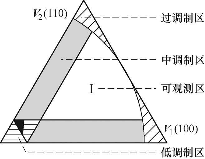
图5 扇区Ⅰ电压调制区域
Fig.5 Modulation area in sector I
表2 各调制区有效矢量作用时间
Tab.2 Action time of vector in each modulation area
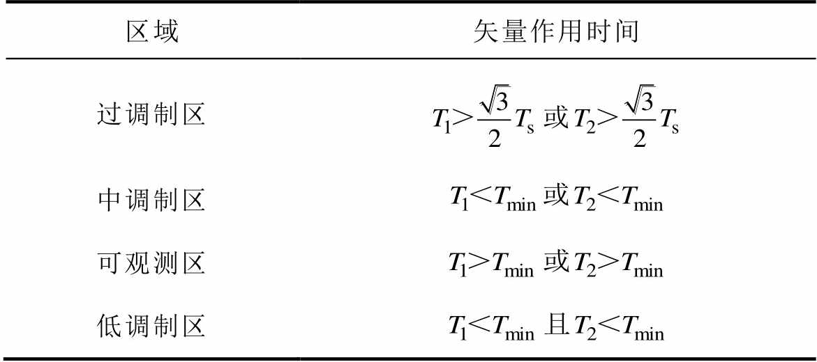
区域矢量作用时间 过调制区 中调制区 可观测区 低调制区
为了改进中调制盲区的电流重构效果,提出了CNSVPWM方法,扇区Ⅰ的CNSVPWM基本原理如图6所示。
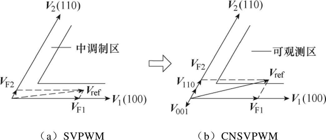
图6 扇区Ⅰ的CNSVPWM基本原理
Fig.6 Principle of CNSVPWM in sector Ⅰ
VF1和VF2用于合成参考电压矢量Vref,在中调制区添加V110延长VF2矢量,同时用互补非零矢量V001在相反方向加以抵消,互补矢量作用时间满足
 (4)
(4)
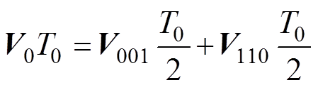
插入互补非零矢量作用效果与零矢量相同,根据伏秒平衡原理,补偿后的电压矢量满足
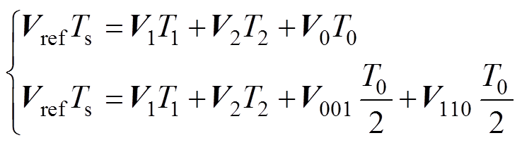 (5)
(5)
由于扇区两侧中调制区需要延长的有效矢量不同,所以在采用CNSVPWM方法后各扇区会产生两组PWM脉冲波形,对应扇区前后两侧需要延长的有效矢量。表3为CNSVPWM的矢量切换顺序。
表3 CNSVPWM矢量切换顺序
Tab.3 CNSVPWM vector switch sequence
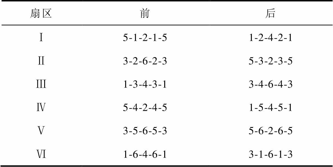
扇区前后 Ⅰ5-1-2-1-51-2-4-2-1 Ⅱ3-2-6-2-35-3-2-3-5 Ⅲ1-3-4-3-13-4-6-4-3 Ⅳ5-4-2-4-51-5-4-5-1 Ⅴ3-5-6-5-35-6-2-6-5 Ⅵ1-6-4-6-13-1-6-1-3
CNSVPWM相电流重构原理如图7所示。传统SVPWM方法下扇区Ⅰ的PWM控制周期内,只能在电压矢量V110作用时采样得到电流-ic,在V100作用时无法得到相电流信息。图7b采用互补非零矢量脉宽调制方法,中调制区添加互补矢量V1(100)和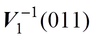 ,延长后电流采样窗口时间Tsp1和Tsp2均满足最小采样时间要求,对应两相电流-ic和ib。各扇区前后CNSVPWM方法如图8所示。
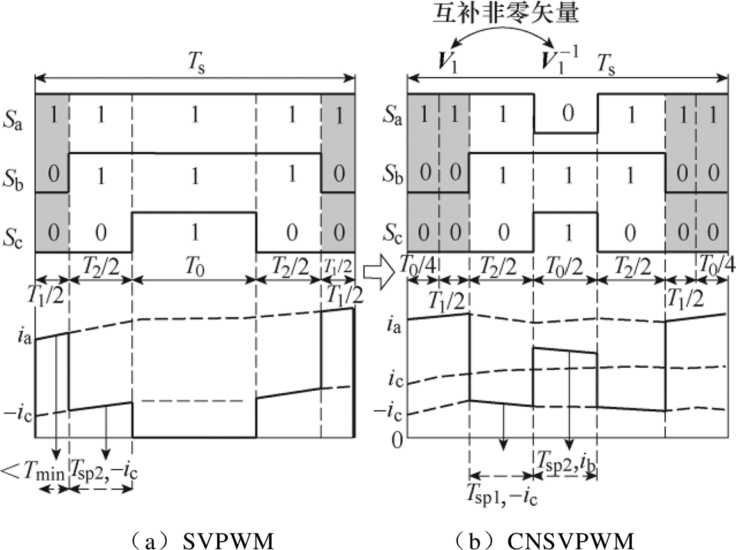
图7 CNSVPWM重构原理
Fig.7 Reconstruction principle of CNSVPWM
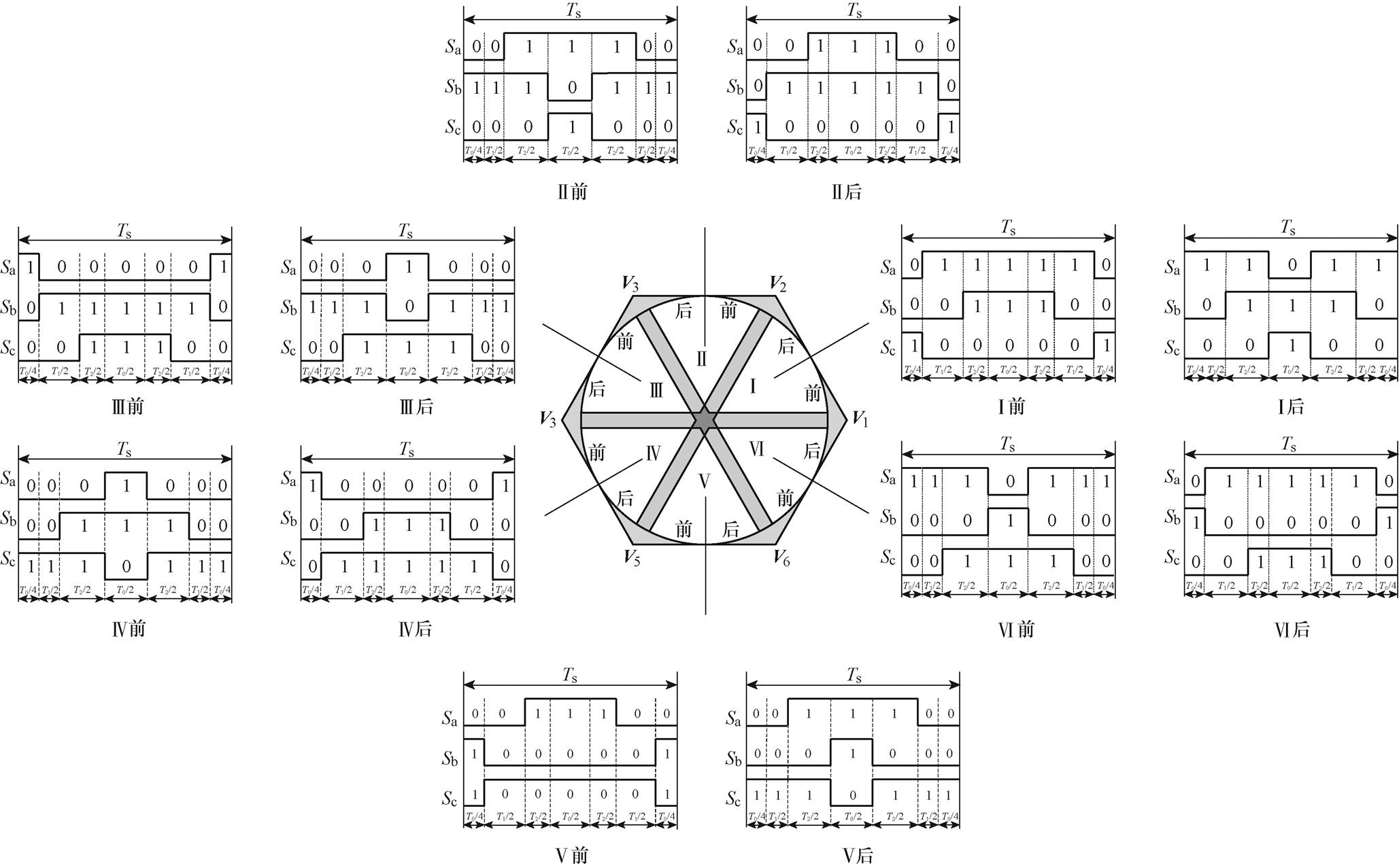
图8 各扇区前后CNSVPWM方法
Fig.8 CNSVPWM in every sector front and back
综上所述,通过CNSVPWM方法对采样窗口的延长能够实现电压空间矢量平面中调制盲区的相电流重构。
在Matlab/Simulink中搭建仿真模型对所提方法进行验证,控制原理框图如图9所示。调制度M设置为0.55,PWM载波频率设置为10 kHz,采样频率为20 kHz。
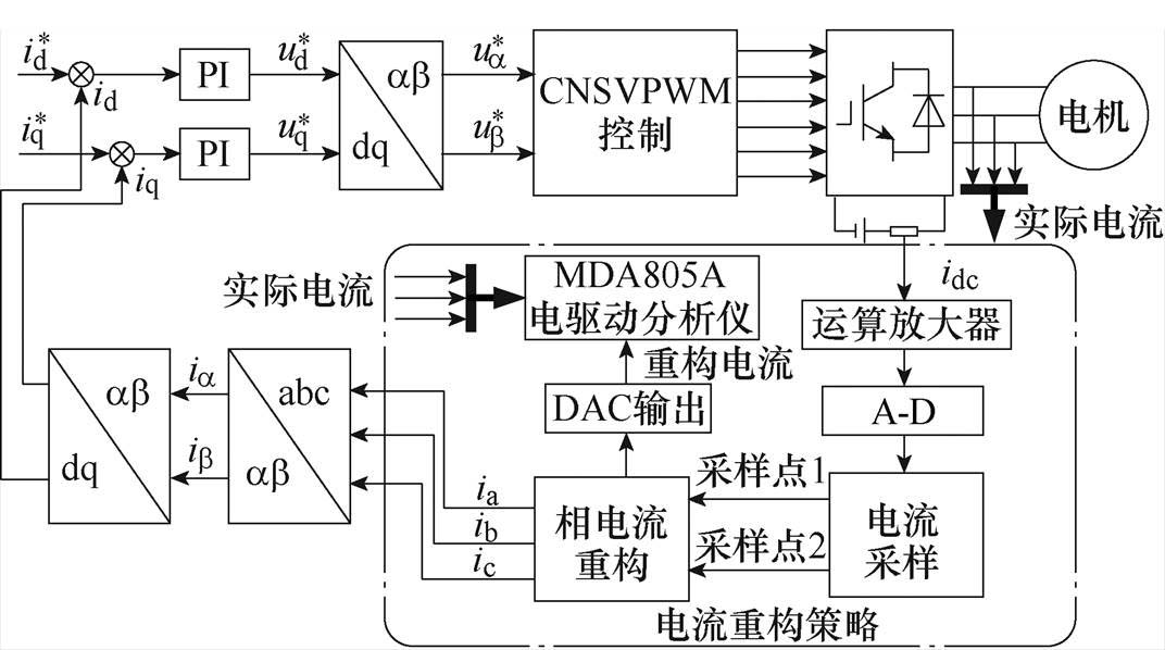
图9 系统控制原理框图
Fig.9 System control principle block diagram
图10为实际相电流与重构相电流以及定子磁链矢量轨迹在SVPWM方式下对比。通过仿真结果可以看出,直流母线单传感器采样方法在扇区边界中调制区受最小采样时间的限制,无法保证电流准确采样,三相电流不能实现完整重构,定子磁链矢量轨迹不再是圆形。
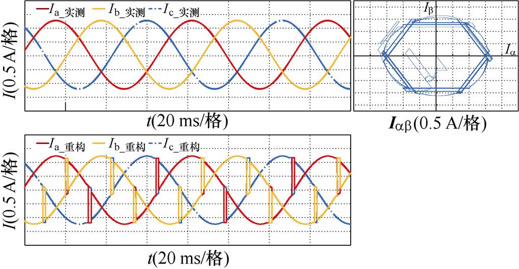
图10 实际相电流与重构相电流以及定子磁链矢量轨迹在SVPWM方式下对比
Fig.10 Comparison diagram of actual phase current, reconstructed phase current and stator flux vector trajectory under SVPWM mode
图11为在SVPWM方式下实际相电流与重构相电流以及定子磁链矢量轨迹对比,扇区边界的中调制盲区已被成功消除,能够实现相电流的完整重构,重构电流与实际电流保持一致,定子磁链矢量轨迹比较平滑,仿真负载电机可以平稳运行。
通过仿真结果得出,SVPWM方法下,中调制盲区无法重构电流,仿真结果与理论分析一致。同时低调制盲区和高调制盲区仍然存在,原因是在过调制下有效电压矢量持续时间全部小于最小采样时间,同时伴随DAC通道转换带来的延迟,盲区的存在反映了空间电压矢量平面不能被完全调制的特性。
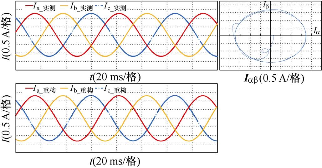
图11 实际相电流与重构相电流以及定子磁链矢量轨迹在CNSVPWM方式下对比
Fig.11 Comparison diagram of actual phase current, reconstructed phase current and stator flux vector trajectory under CNSVPWM mode
实验平台如图12所示,采用TMS320F28035型DSP的高压电机控制器对CNSVPWM方法进行测试。PWM载波频率为10 kHz,采样频率20 kHz,三相感应电机48T17D2000K为控制系统的驱动电机。实验数据的采集和分析通过力科MDA805A电驱动分析仪完成。表4为三相感应电机参数。
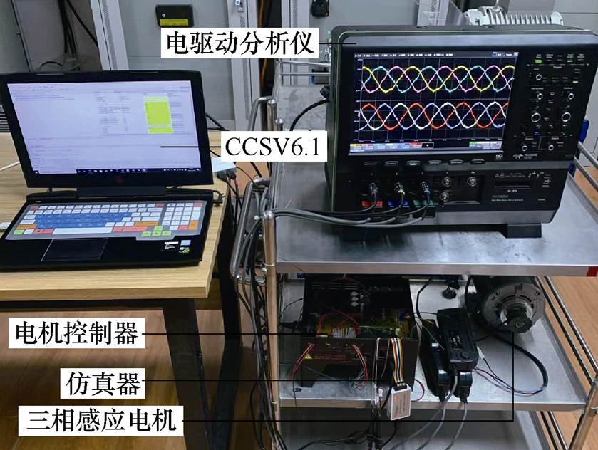
图12 实验平台
Fig.12 Experimental platform
表4 三相感应电机参数
Tab.4 Parameters of three phase induction motor
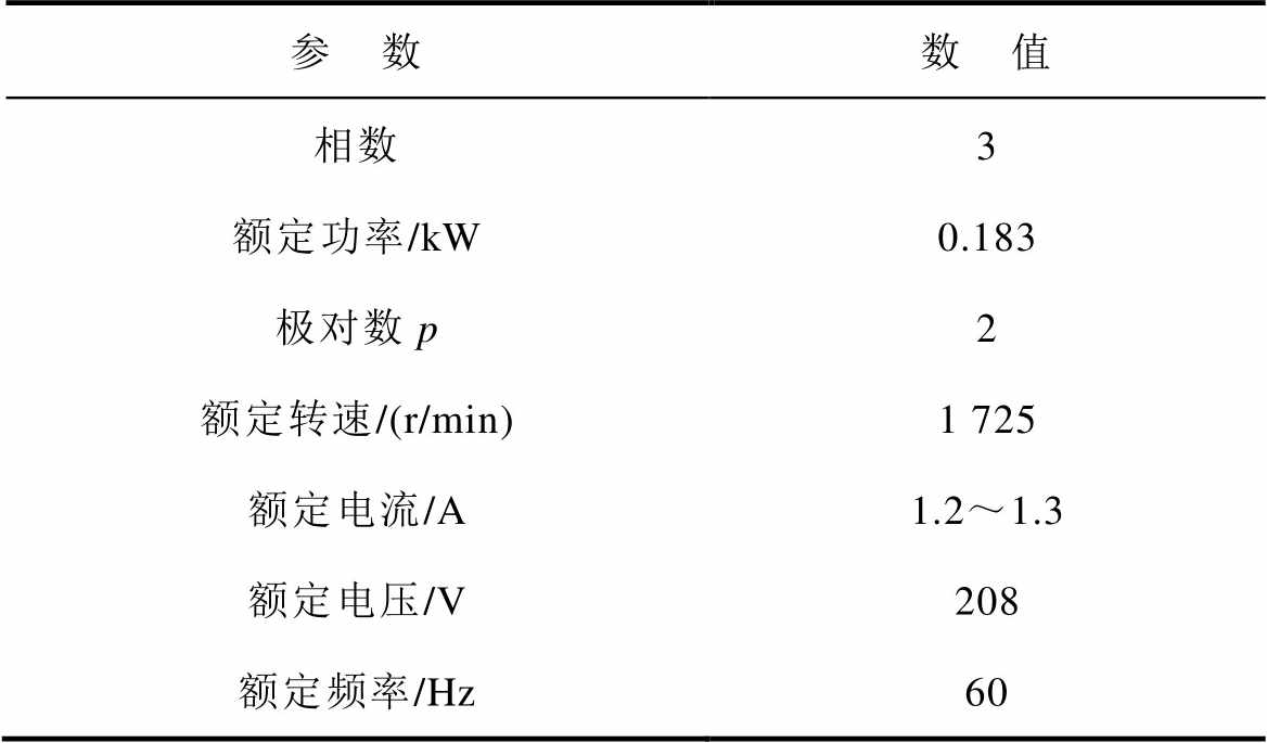
参 数数 值 相数3 额定功率/kW0.183 极对数p2 额定转速/(r/min)1 725 额定电流/A1.2~1.3 额定电压/V208 额定频率/Hz60
图13为电机运行在扇区Ⅰ时的PWM波形和直流母线电流波形。可以看出,插入互补非零矢量后采样窗口被延长,CNSVPWM波形正常,两次采样脉冲可以精确触发。逆变器的开关特性会导致电流振荡点的产生,经过最小采样时间后直流母线电流趋于稳定,与理论分析一致。
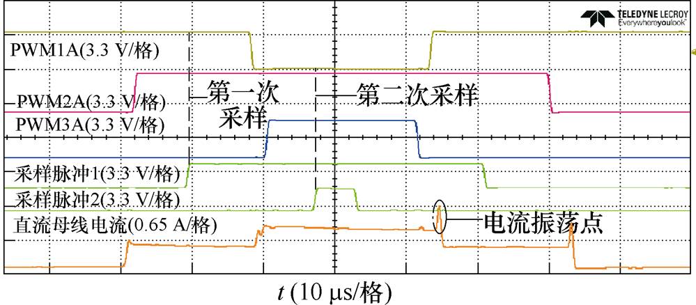
图13 PWM和直流母线电流波形
Fig.13 PWM and DC bus current waveforms
实验在传统SVPWM模式下,开环运行时重构电流与实际电流的波形如图14所示。实验中,频率为15.6 Hz,调制度M=0.55,转速468 r/min,可见重构出的相电流会在扇区中调制盲区时发生畸变。定义Ire为重构电流,Iac为实际电流,重构误差可通过式(6)计算得出,为4.27 %。重构误差波形如图14c所示,重构误差为
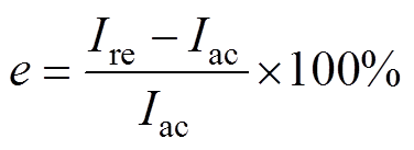 (6)
(6)
CNSVPWM模式下重构电流与实际电流对比如图15所示。从图15中可以看出,在CNSVPWM模式下,重构出的相电流和实际电流波形基本一致且能保持较好的正弦度,重构误差为2.72 %。
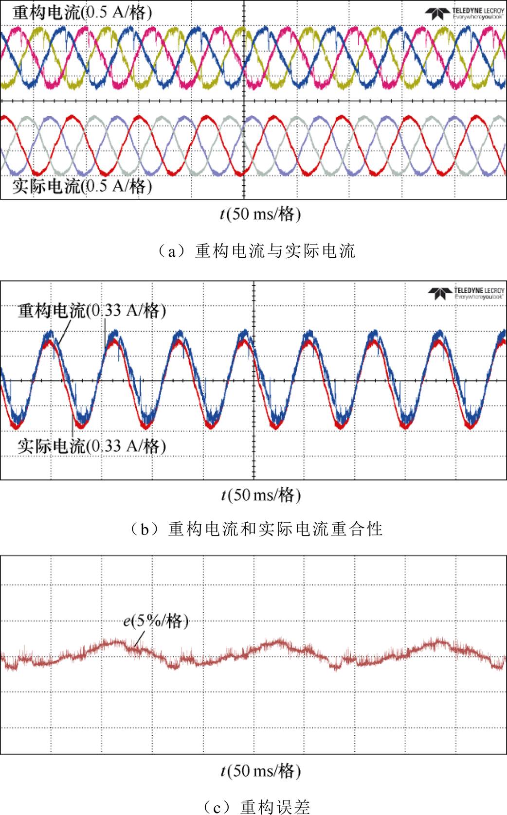
图14 SVPWM模式下重构电流与实际电流对比
Fig.14 Comparison of reconstruct current and actual current under SVPWM
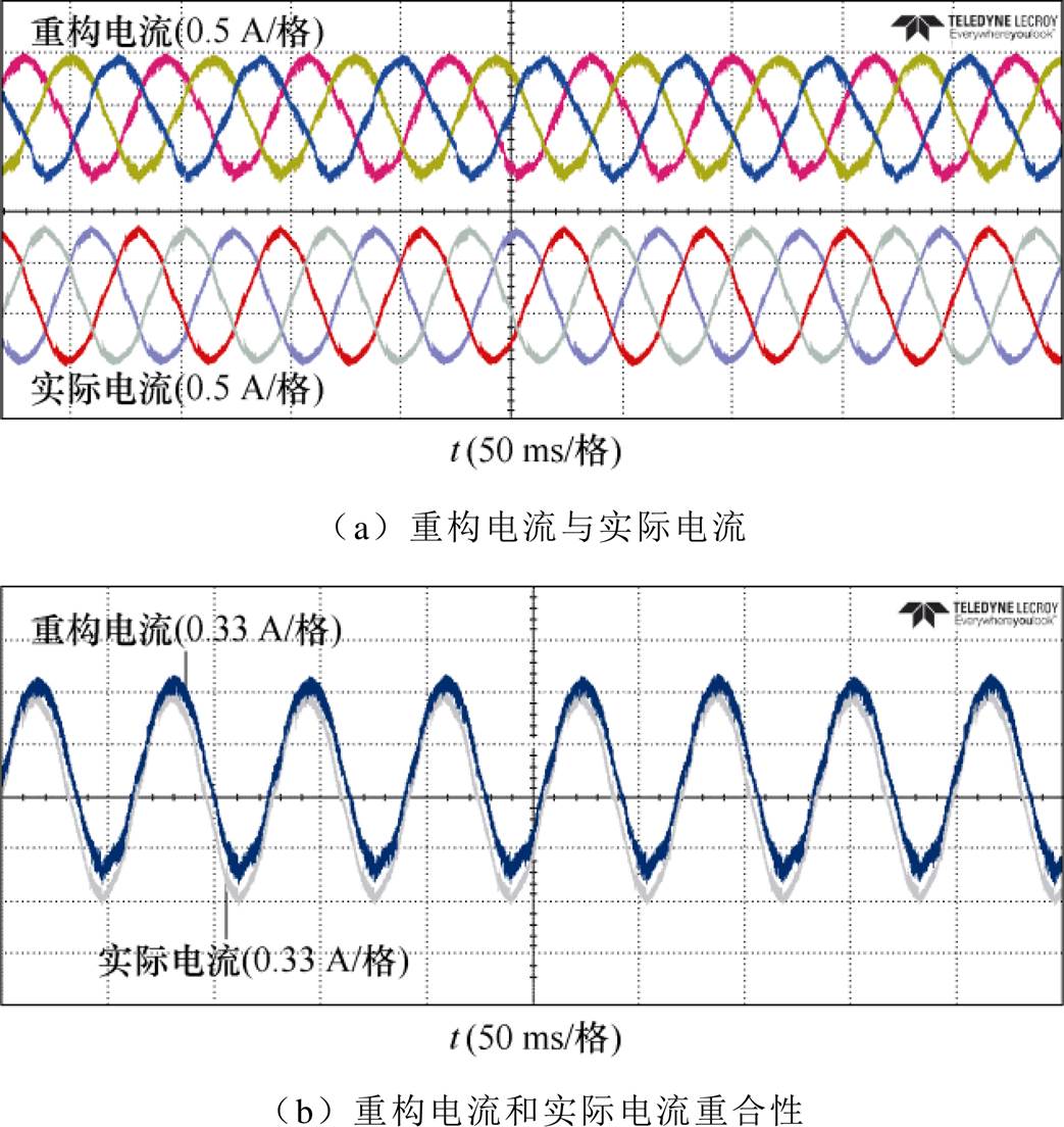
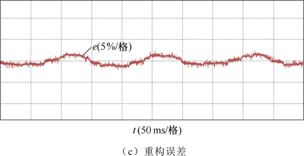
图15 CNSVPWM模式下重构电流与实际电流对比
Fig.15 Comparison of reconstruct current and actual current under CNSVPWM
图16为分别采用SVPWM和CNSVPWM策略,系统开环运行时实测电流谐波。可以看出,传统SVPWM策略电流的总谐波畸变率(Total Harmonic Distortion, THD)为4.11 %。采用CNSVPWM的电流谐波略有上升,THD=6.15 %。
为了进一步验证所提出方法在电机运行于动态工况时的有效性,在不同的工况下进行了实验,主要包括电机开环平稳运行和加速减速过程,如图17所示。

图16 SVPWM和CNSVPWM方式下THD对比
Fig.16 THD comparison of SVPWM and CNSVPWM
电机在起动完成后,分别进入加速和减速阶段运行,并没有出现电流波动的情况,重构电流可以跟随实际电流进行实时变化。实验结果证明了所提调制方法下电机的动态性能良好。
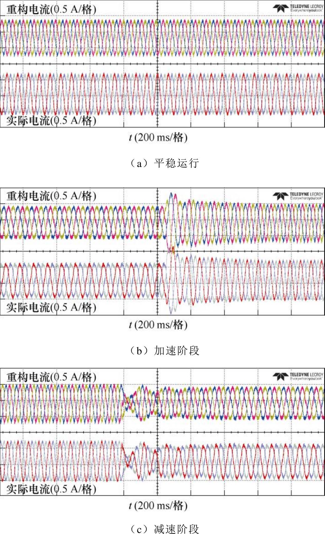
图17 平稳运行、电机加速和电机减速
Fig.17 Stable operation, motor acceleration and motor deceleration
本文针对传统SVPWM方法在扇区中调制盲区时无法成功重构三相电流问题。提出了一种CNSVPWM技术。通过实验验证其主要特性如下:
1)CNSVPWM方法保持PWM波形的对称性,不会对占空比造成影响。
2)CNSVPWM增大了电流采样窗口,实现了中调制盲区的相电流重构。
3)实测电流THD略有提升,保持在6.15 %以下,重构误差低于3 %。
该方法不足之处在于,由于复合母排结构难以在直流母线上添加传感器,因此不适用于复合母排结构的电机控制系统。
CNSVPWM仅关注了重构电流的精度以及PWM方法对THD的影响,是在开环状态下进行的测试,进一步分析重构电流对闭环控制系统的影响是下一步研究工作的重点。
参考文献
[1] Xu Yongxiang, Yuan Qingbing, Zou Jinbin, et al. Sinusoidal periodic carrier frequency modulation in reducing electromagnetic noise of permanent magnet synchronous motor[J]. IET Electric Power Appli- cations, 2013, 7(3): 223-230.
[2] Cheng Xiaomeng, Lu Haifeng, Qu Wenlong, et al. Single current sensor operation with fixed sampling points using a common-mode voltage reduction PWM technique[C]//2009IEEE6th International Power Elec- tronics and Motion Control Conference, Wuhan, China, 2009: 479-483.
[3] 魏海峰, 陆彦如, 江廷宇, 等. 考虑非观测区补偿的永磁同步电机单电阻采样重构[J]. 电工技术学报, 2018, 33(12): 2695-2702.
Wei Haifeng, Lu Yanru, Jiang Tingyu, et al. Single resistor sampling reconstruction of permanent magnet synchronous motor considering non-observation area compensation[J]. Transactions of China Electrotech- nical Society, 2018, 33(12): 2695-2702.
[4] Sun Kai, Wei Qing, Huang Lipei, et al. An over- modulation method for PWM-inverter-fed IPMSM drive with single current sensor[J]. IEEE Transactions on Industrial Electronics, 2010, 57(10): 3395-3404.
[5] 周聪, 刘闯, 王凯, 等. 用于开关磁阻电机驱动系统的新型单电阻电流采样技术[J]. 电工技术学报, 2017, 32(5): 55-61.
Zhou Cong, Liu Chuang, Wang Kai, et al A novel single resistance current sampling technique of switched reluctance motor[J]. Transactions of China Electrotechnical Society, 2017, 32(5): 55-61.
[6] 翁汉琍, 贾永波, 李振兴, 等. 二维空间重构电流特征轨迹的变压器差动保护判据[J]. 电力系统自动化, 2020, 44(9): 144-150.
Weng Hanli, Jia Yongbo, Li Zhenxing, et al. Transformer differential protection criterion based on reconstructed trajectory of current characteristics in two-dimensional space[J]. Automation of Electric Power Systems, 2020, 44(9): 144-150.
[7] 赵仕策, 赵洪山, 寿佩瑶. 智能电力设备关键技术及运维探讨[J]. 电力系统自动化, 2020, 44(20): 1-10.
Zhao Shice, Zhao Hongshan, Shou Peiyao. Discussion on key technology and operation & maintenance of intelligent power equipment[J]. Automation of Elec- tric Power Systems, 2020, 44(20): 1-10.
[8] 黄科元, 伍瑞泽, 黄守道, 等. 单电阻采样的永磁同步电动机相电流重构策略[J]. 电力系统及其自动化学报, 2018, 30(9): 114-120.
Huang Keyuan, Wu Ruize, Huang Shoudao, et al. Phase current reconstruction strategy for PMSM using one-shunt current sampling[J]. Proceedings of the CSU-EPSA, 2018, 30(9): 114-120.
[9] 陆佳琪, 吴金富, 陆彦如, 等. 永磁同步电机新型单电阻电流重构技术研究[J]. 电机与控制应用, 2019, 46(2): 46-51.
Lu Jiaqi, Wu Jinfu, Lu Yanru, et al. A novel single- resistance current reconfiguration technique for per- manent magnet synchronous motor[J]. Electric Machines & Control Application, 2019, 46(2): 46-51.
[10] 马鸿雁, 孙凯, 魏庆, 等. PWM逆变器相电流重构研究与误差分析[J]. 电工技术学报, 2011, 26(1): 108-114, 161.
Ma Hongyan, Sun Kai, Wei Qing, et al. Phase current reconstruction method for PWM inverter and error analysis[J]. Transactions of China Electrotechnical Society, 2011, 26(1): 108-114, 161.
[11] Lee W C, Hyun D S, Lee T K. A novel control method for three-phase PWM rectifiers using a single current sensor[J]. IEEE Transactions on Power Electronics, 2000, 15(5): 861-870.
[12] Lai Y S, Lin Yongkai, Chen C W. New hybrid pulse width modulation technique to reduce current dis- tortion and extend current reconstruction range for a three-phase inverter using only DC-link sensor[J]. IEEE Transactions on Power Electronics, 2013, 28(3): 1331-1337.
[13] 王文杰, 闫浩, 邹继斌, 等. 基于混合脉宽调制技术的永磁同步电机过调制区域相电流重构策略[J]. 中国电机工程学报, 2021, 41(17): 6050-6060.
Wang Wenjie, Yan Hao, Zou Jibin, et al. Phase current reconstruction strategy of PMSM under over- modulation mode based on a hybrid space vector pulse width modulation technique[J]. Proceedings of the CSEE, 2021, 41(17): 6050-6060.
[14] Lu Haifeng, Cheng Xiaomeng, Qu Wenlong, et al. A three-phase current reconstruction technique using single DC current sensor based on TSPWM[J]. IEEE Transactions on Power Electronics, 2014, 29(3): 1542-1550.
[15] 闫朝阳, 张喆, 李建霞, 等. 单相高频链逆变器的解结耦单极性移相调制及其死区优化[J]. 电工技术学报, 2018, 33(6): 1337-1346.
Yan Zhaoyang, Zhang Zhe, Li Jianxia, et al. The uni-polarity phase-shifted modulation strategy for single-phase high-frequency link inverter based on de-re-coupling idea and dead time optimization[J]. Transactions of China Electrotechnical Society, 2018, 33(6): 1337-1346.
[16] 申永鹏, 王前程, 王延峰, 等. 误差自校正混合脉宽调制策略[J]. 电工技术学报, 2022, 37(14): 3643- 3653.
Shen Yongpeng, Wang Qiancheng, Wang Yanfeng, et al. Error self-correction mixed pulse width modu- lation strategy[J]. Transactions of China Electro- technical Society, 2022, 37(14): 3643-3653.
[17] 申永鹏, 王帅兵, 梁伟华, 等. T型三电平逆变器合成脉冲宽度调制相电流重构策略[J]. 电工技术学报, 2022, 37(20): 5302-5312.
Shen Yongpeng, Wang Shuaibing, Liang Weihua, et al. T-type three-level inverter composite pulse width modulation phase current reconstruction strategy[J]. Transactions of China Electrotechnical Society, 2022, 37(20): 5302-5312.
[18] 肖飞, 许观达, 连传强, 等. 永磁同步电机单电流传感器系统的三相电流重构策略[J]. 电工技术学报, 2022, 37(7): 1609-1617.
Xiao Fei, Xu Guanda, Lian Chuanqiang, et al. Three- phase current reconstruction strategy of permanent magnet synchronous machine drives using a single current sensor[J]. Transactions of China Electro- technical Society, 2022, 37(7): 1609-1617.
[19] 黄梓欣, 林湘宁, 马啸, 等. 含风电继电保护应用中的电流互感器饱和电流重构方法[J]. 电工技术学报, 2022, 37(19): 4823-4834.
Huang Zixin, Lin Xiangning, Ma Xiao, et al. Recon- struction method of saturation current of current transformer in relay protection application related to wind power[J]. Transactions of China Electrote- chnical Society, 2022, 37(19): 4823-4834.
[20] 谷明月, 何媛媛. 基于半PWM移相的单电阻电流重构策略研究[J]. 微电机, 2019, 52(6): 62-66.
Gu Mingyue, He Yuanyuan. Research on single-shunt current sensing method based on half PWM phase shift[J]. Micromotors, 2019, 52(6): 62-66.
[21] Ha J I. Current prediction in vector-controlled PWM inverters using single DC-link current sensor[J]. IEEE Transactions on Industrial Electronics, 2010, 57(2): 716-726.
[22] Gu Yikun, Ni Fenglei, Yang Dapeng, et al. Switching- state phase shift method for three-phase-current reconstruction with a single DC-link current sensor[J]. IEEE Transactions on Industrial Electronics, 2011, 58(11): 5186-5194.
[23] Lu Jiadong, Zhang Xiaokang, Hu Yihua, et al. Independent phase current reconstruction strategy for IPMSM sensorless control without using null switching states[J]. IEEE Transactions on Industrial Electronics, 2018, 65(6): 4492-4502.
[24] 申永鹏, 郑竹风, 杨小亮, 等. 直流母线电流采样电压空间矢量脉冲宽度调制[J]. 电工技术学报, 2021, 36(8): 1617-1627.
Shen Yongpeng, Zheng Zhufeng, Yang Xiaoliang, et al. A compatible SVPWM method for DC bus current sampling[J]. Transactions of China Electrotechnical Society, 2021, 36(8): 1617-1627.
[25] Im J H, Kim R Y. Improved saliency-based position sensorless control of interior permanent-magnet syn- chronous machines with single DC-link current sensor using current prediction method[J]. IEEE Transa- ctions on Industrial Electronics, 2018, 65(7): 5335- 5343.
[26] 倪瑞政, 李庭, 陈杰, 等. 一种脉冲式死区补偿方法的研究[J]. 电工技术学报, 2019, 34(增刊2): 553-559.
Ni Ruizheng, Li Ting, Chen Jie, et al. Research on a pulse dead zone compensation method[J]. Transa- ctions of China Electrotechnical Society, 2019, 34(S2): 553-559.
Abstract With the development of power electronics and control theory, AC drive systems are widely used in industrial production, transportation, military aerospace, and other fields. In the AC servo control system, the motor phase current is the core parameter to the vector control, and the detection and feedback of the phase current are of great significance in improving the control system’s performance. The traditional vector control system needs at least two current sensors installed on the AC output side through the space voltage pulse width modulation (SVPWM) method to achieve phase current acquisition and real-time feedback. Multiple sensors will inevitably increase the system cost and equipment volume, which is not conducive to the development of control equipment miniaturization. Furthermore, the inconsistencies between multiple sensors will deteriorate the performance of the system. To improve these problems, based on the DC bus single sensor sampling principle and traditional SVPWM method, this paper proposes a complementary non-zero vector pulse width modulation (CNSVPWM) method. CNSVPWM utilizes the DC bus single sensor to carry out the phase current time-sharing acquisition under the action of the complementary non-zero vectors and complete the reconstruction of three-phase currents. Thus, accurate feedback on current information is achieved while reducing the cost and volume of the control system.
Firstly, according to the switching states of the three-phase two-level inverter, six effective voltage vectors and two zero vectors are defined, and the corresponding relationship between the DC bus current idc and the phase current can be obtained. Then, the characteristics of the switching devices and the establishment process of the DC bus current are analyzed. The shortest time for the DC bus current to reach a steady state is obtained. That is, the minimum sampling time Tmin for current sampling. According to the minimum sampling time, each sector is divided into the observable area, sector boundary, and low modulation area. The effective voltage vector not meeting the minimum sampling time requirement is defined as a current reconstruction blind area, where the current cannot be completely reconstructed. Aiming at the current reconstruction blind area and based on the volt-second balance principle, the CNSVPWM method utilizes a pair of complementary non-zero vectors to extend the voltage vector action time. For the CNSVPWM method, the duty cycle of effective vectors in each carrier period TS does not change, and the symmetry of the PWM is retained.
In the open-loop experiments, the PWM carrier frequency is set to 10 kHz, the sampling frequency is 20 kHz, and the modulation index is M=0.55. MDA805A motor drive analyzer is used to collect and analyze the experimental data. In sector switching, the CNSVPWM waveform is normally sent, and two sample pulses can be accurately triggered. When the reference voltage vector enters the sector boundary area, the three-phase current can be completely reconstructed, and the reconstruction error is 2.72 %. To further verify the effectiveness of the proposed method, the experiments are carried out under two dynamic conditions of motor acceleration and deceleration. When the rotational speed changes, the reconstructed phase current can follow the measured phase current in real-time. The FFT results show that compared with the SVPWM method, the current harmonic THD of CNSVPWM is increased by 2.04 %, from 4.11 % to 6.15 %.
The following conclusions are drawn through experiments: (1) The CNSVPWM method retains the symmetry of the PWM waveform and does not affect the duty cycle. (2) The CNSVPWM extends the current sampling window and realizes the phase current reconstruction in the middle modulation area. (3) The current THD of CNSVPWM is less than 6.15 %, reconstruction error is less than 3 %.
keywords:DC bus sampling, single sensor, space vector pulse width modulation (SVPWM), phase current reconstruction
DOI: 10.19595/j.cnki.1000-6753.tces.220071
中图分类号:TM341
国家自然科学基金面上项目(62273313, 62173134)、河南省科技攻关项目(222102240005)、河南省青年骨干教师培养计划项目(2021GGJS089)、郑州市协同创新专项项目(2021ZDPY0204)和河南省自然科学基金项目(222300420373)资助。
收稿日期 2022-01-16
改稿日期 2022-09-09
申永鹏 男,1985年生,博士,副教授,研究方向为电动汽车动力系统驱动与控制、能量管理与优化。E-mail: shenyongpeng@zzuli.edu.cn(通信作者)
武克轩 男,1999年生,硕士研究生,研究方向为电机调速与控制。E-mail: wkx1932@126.com
(编辑 陈 诚)