 。
。摘要 阀电流是晶闸管型换流器运行状态的直接体现形式。为提升换流器的能观性,该文提出一种利用阀侧电流时序特征实时计算阀电流的方法。首先,利用交直流电流的时序特性预估每个阀的导通/关断状态。其次,根据阀状态计算换流器的旁通组数,利用多相旁通组间的并联关系,构造旁通回路方程。最后,计算阀电流,利用阀的单向导电性,校正阀关断状态和阀电流。仿真和录波结果表明:在不同的阀状态和旁通组数下,所提方法均能准确计算换相失败暂态过程及其故障恢复期间的阀电流,验证了其有效性。
关键词:阀电流 阀侧电流 时序特征 预估阀状态 旁通回路方程 阀关断状态校正
换流器是高压直流输电(High Voltage Direct Current, HVDC)系统电力变换的核心设备,其性能直接决定电网的运行能力[1-2]。晶闸管型换流器是非线性元件,交流故障后换流器的运行工况和电流变化比较复杂[3]。当长时间、大容量电流流过换流阀时,易造成高温,从而导致阀设备的寿命降低或内部元件的损坏。为保证阀设备的安全、提升换流器的能观性[4]和可靠性,研究换流器运行状态的实时监测是实现阀内部特征反馈到控制系统进行调节的重要条件。
目前,换流阀中各种信号和运行状态的测量、采样及控制主要依赖系统内部阀基电子设备的自 检[5-6],缺乏外部实时检测手段。换流阀的运行状态只能通过换流器端口的外部信息间接反映[7],而暂态过程中,换流器端口电气量与换流阀内部特征的差异较大,不能准确表征换流器复杂的运行状态。因此,从电流反映和观测角度看,检测换流器内部阀电流对提升换流器运行状态的感知能力、优化换流器的控保能力具有重要意义。
现有研究关于传统高压直流输电换流器各阀电流的解析相对较少,主要从换流器建模方面研究阀电流的计算。文献[8-9]以三相交流电压瞬时值为输入量,利用换流阀运行状态与拓扑结构,建立节点电压方程,求出阀电流和阀电压等电气量信息。但文献[8-9]简化了换流阀的开关模型,该方法在交直流混联电网中不适用。换流阀的导通和关断状态可以确定换流器各阀电流的分布,研究者们采用开关函数[10-12]对换流器内部运行参数进行了一些研究。文献[13-14]将开关函数模型和动态相量模型相结合,对阀电流进行求解。然而,开关函数不仅受触发脉冲的影响,还受其两端电压和流通电流的影响。当换流器在稳态运行时,开关函数比较稳定,可以计算阀电流;在暂态过程中,特别是换相失败及其故障恢复过程,开关函数无法反映换流阀实际运行状态,导致阀电流的计算存在误差。
阀电流与阀状态之间具有相互耦合的关系,如何利用两者的约束关系,实现阀电流的求解是本文的研究重点。因此,为了克服现有研究的不足,本文从换流器的拓扑结构出发,提出一种基于阀侧交直流电流时序特征的阀电流实时计算方案。通过仿真对比和录波数据分析,验证所提方法的有效性。
传统高压直流输电系统基本换流单元是由上、下两个结构相同的三相全桥6脉换流器组成的12脉换流器。不失一般性,本文以6脉换流器为例进行分析,其拓扑结构如图1所示。图1中,M、N分别为换流器的共阴极点和共阳极点;n为交流系统的中心点;a、b、c点分别为阀对V4与V1、V6与V3、V2与V5的中心端点;Lc为换相电抗;Zeq为交流系统等值阻抗;ea、eb、ec为电源电压;ia、ib、ic为阀侧三相交流电流;idH为高压侧直流电流;idN为低压侧直流电流;uMN为换流器端电压;im为阀电流, 。
。
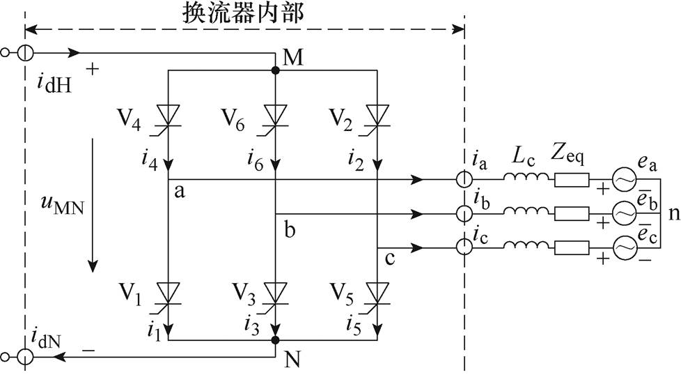
图1 换流器的拓扑结构
Fig.1 The topology structure of the converter
换流阀由多个晶闸管等器件串联组成,内部可等效为电阻。当晶闸管处于通态[15]时,等效的通态电阻很小,用Ron表示;当晶闸管处于断态[16]时,等效的断态电阻很大,用Roff表示。
根据换流器电路拓扑结构约束,当换流器内部无故障时,阀侧的三相交流电流的矢量和等于0。建立一组换流器的端口电流与阀电流的非齐次线性方程 ,此方程称为拓扑方程[17]。具体为
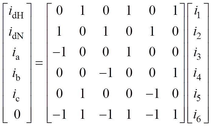 (1)
(1)
式中, 为拓扑方程的系数矩阵;
 为阀电流的向量;
 为阀侧交直流电流的向量。
拓扑方程的秩等于4,独立方程小于未知变量的数量。为确定电流分布,在拓扑方程的基础上需引入阀状态 ,构造反映导通阀电流与换流器端口电流的关联方程
 。其中,
。其中, 为关联方程的系数矩阵,
 、
、 、
、 、
、 、
、 、
、 为V1~V6的阀状态。对角阀状态矩阵
 为
为
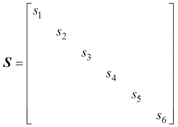 (2)
(2)
关联方程 具体为
具体为
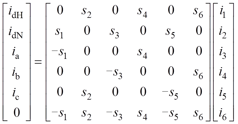 (3)
(3)
正常运行时,6脉波换流器在60°的重复周期中,2个和3个换流阀轮流导通,此运行方式称为2~3工况,换流阀轮换导通的时序特征是确定的。由式(1)可知,阀电流与交流电流的极性值之间存在严格的对应关系,即根据交流电流的极性特征可以得到阀电流。
在逆变侧换流母线处设置三相故障,阀侧交直流电流、根据交流电流极性特征得到的正负向电流幅值(简称为极性值)和阀电流的实际值如图2所示。
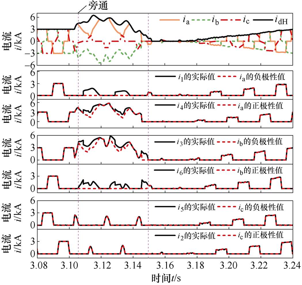
图2 交流电流极性特性与阀电流实际值的对比
Fig.2 A comparison between polarity current of AC current and actual current under AC fault
故障前,换流器同相的上、下两阀只有一个阀导通,交流电流的极性值等于阀电流实际值。表明正常运行时利用交流电流的极性特征可以计算阀电流。故障后,直流换相失败及其恢复过程中存在同相上、下两阀同时导通的情况。如图2中a相和b相形成旁通,此时交流电流的极性值与阀电流实际值不再相等。
换流器换相失败后通过换流阀形成旁通回路,引发直流电流与交流电流间出现差异。这种差异是极性电流与阀电流实际值存在差异的本质原因。因此,在故障暂态过程换流器出现旁通及其恢复过程中,无法利用交流电流极性特征获取阀电流。故在换流器出现旁通及其后续退出旁通时,需要重新制定阀电流的求解方法。
计算准确的阀电流是解决换流器运行状态在线检测的核心关键技术。根据关联方程可知,为计算每个阀的电流,需判断阀的导通和关断状态;在计算暂态过程的阀电流时,因多阀导通而关联方程个数不够的问题,需要增补方程数。
2.1.1 基于电流时序特性判别阀状态的分析
单阀导通/关断的转换条件及电流特征如图3所示:当阀Vm有触发脉冲Pm且承受的阀电压um为正时,正在关断的阀Vm开始导通,阀电流增加。当阀电流超过擎住电流,阀Vm保持通态,直到导通阀Vm承受反向电压。此后阀电流im开始降低直至为0且满足最小熄弧时间,阀Vm彻底关断,进入断态。
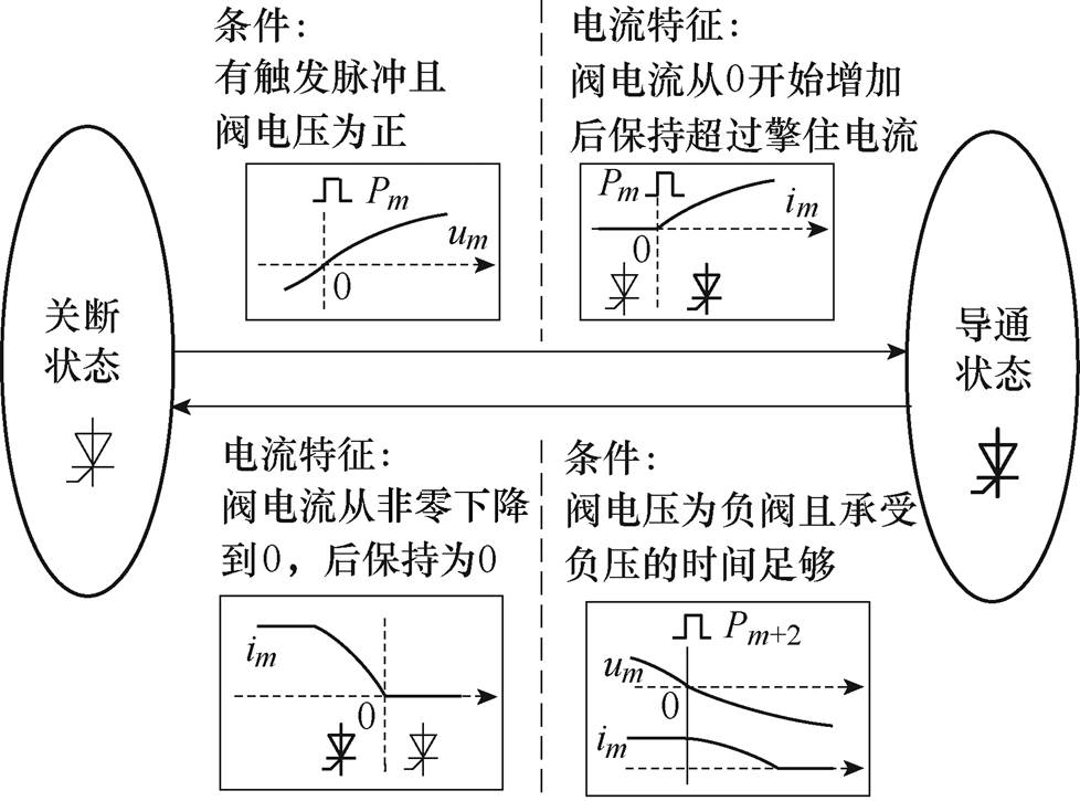
图3 单阀的导通/关断的条件及电流特征
Fig.3 The requirement of valve on the on-state and off-state and the current feature
根据阀导通和关断条件可知,在判别阀的状态时应该引入阀端电压。但实际工程中阀端没有安装电压互感器,端电压不可直接获取。由图3可知,当阀电压为负时,阀电流才开始降低,并非为阀电流过零点时刻。因此,即使阀电压已知,也不能直接确定阀关断的时刻。故从工程实用性的角度,本文提出仅从电流的特性入手构造判别阀状态的判据。
导通和关断两状态间的切换判别以及与其他阀的状态间的切换,需要当前时刻的电气量和前一时刻状态共同决定。这种电气量和状态量在时间序列上的变化规律简称为时序特征。根据电流的时序特征,确定正在导通的阀是否会被关断、正在关断的阀是否会被导通。
2.1.2 基于电流时序特性的阀状态判别
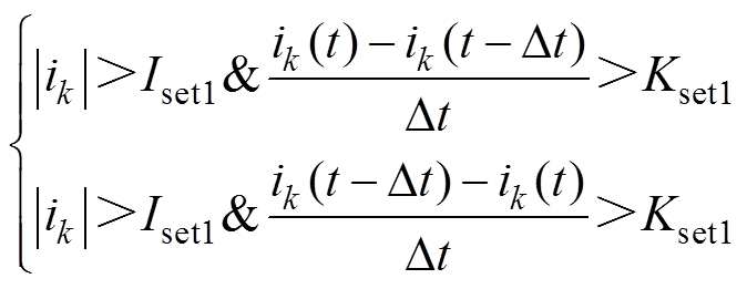
由图3可知,根据三相交流电流的幅值特征和时序特征可判别阀状态。若前一时刻阀为关断状态,当阀脉冲触发时,利用交流电流的幅值特征和突变量的正负方向判断阳极阀和阴极阀的导通状态;若前一时刻阀为导通状态时,当交流电流小于维持电流且电流无突变量时,判别阀为关断状态。
阳极阀和阴极阀导通状态的判据为
 (4)
(4)
式中,ik为阀侧交流电流,k=a, b, c;|ik|为阀侧交流电流的绝对值;Dt为一个采样间隔,实际工程一般取0.1 ms;Iset1为导通状态的门槛定值,取值大于擎住电流与漏电流的和[15];Kset1为导通状态交流电流变化率的门槛值,取决于换相电流变化的陡 度[18],与交流系统支撑强度和换相角有关[19]。
阀关断状态的判据为
 (5)
(5)
式中,Iset2为关断状态的门槛定值,由阀的维持电流决定;Kset2为关断状态下交流电流变化率的门槛值,和Kset1的取值一样。
2.1.3 阀导通状态的修正
根据第1节的分析可知,换流器换相失败后容易形成旁通回路的运行状态,进而衍变为单相旁通对,等效电路如图4所示。图4中,直流电流沿着旁通相流动,三相交流电流均为零。旁通对的两阀均是导通状态,而采用式(5)会误判两阀为关断状态。为实现阀电流的正确计算,亟须对旁通对的阀导通状态进行修正。

图4 单相旁通对的等效电路
Fig.4 Equivalent circuit of single-phase bypass pair
单相旁通对的形成是由于最新触发的阀所在相的两个阀贯穿导通导致。因此,利用触发脉冲间的时序特性可以实现单相旁通对阀导通状态的修正。
构造单相旁通对[20]判别的判据为
 (6)
(6)
式中, 为换相失败门槛定值[21],
 ,
, 为比率制动系数,
 为直流侧电流最大值,
 为启动电流;
 为单相旁通对的门槛定值,由阀的维持电流决定。
实时对换流阀的触发脉冲信号进行锁存、更新。当交直流电流特征首次满足式(6)时,提取被锁存的触发脉冲的编号,即可确定此阀所在的相为旁通相[22]。修正旁通相的阀为导通状态,其他相的阀为关断状态。
2.2.1 换流器关联方程的分析
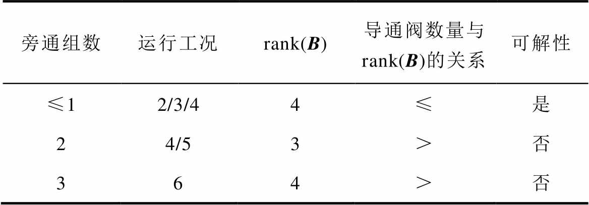
交流故障下,换流器中可能会出现4、5或6个换流阀同时导通的状态,称为运行工况4、5或6。则换流器中会出现1~3个旁通组数,但相同数量的导通阀对应的旁通组数可能不同。换流器的旁通组数、运行工况、关联方程的秩与可解性的关系见表1。受阀电流分布的影响,换流器在不同的运行工况下,关联方程的秩不同。
表1 换流器运行工况与关联方程秩的关系
Tab.1 The relationship between the number of conducting valve and rank(B) of correlation Equ.(3)
旁通组数运行工况rank(B)导通阀数量与rank(B)的关系可解性 ≤12/3/44≤是 24/53>否 364>否
由表1知,关联方程的秩可以求解最多1组旁通组的换流器阀电流。因此,当换流器出现多组旁通时,换流器的运行工况大于关联方程的秩,导致阀电流不能直接求解。为满足阀电流可解,需要增补方程。
2.2.2 旁通回路方程增补
根据判别的阀状态,计算换流器的旁通组数。构造每相的旁通状态和换流器的旁通组数。
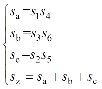 (7)
(7)
式中, 、
、 、
、 代表a、b、c三相的旁通状态,等于1为旁通运行,等于0为非旁通运行;
 为换流器的旁通组数。
换流器出现2组或3组旁通时,基于基尔霍夫电压定律,旁通组与端电压将构成旁通电压回路,旁通组数之间具有一定的关联性。不失一般性,以换流器的运行工况等于6、旁通组是abc三相为例进行分析。
假设导通阀的等效阻抗不变,则各阀的压降表示为
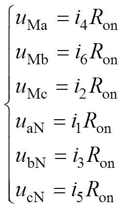 (8)
(8)
式中, 、
、 、
、 、
、 、
、 、
、 分别为阀V1、V2、V3、V4、V5、V6的压降。
旁通组的端电压相等,所以有
 (9)
(9)
联立式(8)、式(9),旁通组间的电流满足
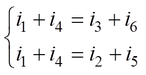 (10)
(10)
式(10)为abc三相旁通时旁通回路方程,其秩等于2。联立式(3)与式(10),可求解唯一的阀电流。
旁通组不同时,旁通回路方程的形式是相同的,只需根据旁通组修改式(10)即可[22]。
2.3.1 换流器阀状态的特殊问题分析
换流器发生换相失败后,原本导通阀将继续导通,直到阀再次承受足够时间反向电压,阀电流才会减小直到关断。由于本节阀状态预估是基于阀电流特性,未考虑电压特征,当换流器在旁通运行时采用式(5)判别阀关断状态会出现误判。以逆变侧单相故障的单相旁通为例,其电气量和状态量的波形如图5所示。

图5 逆变侧电气量和状态量的波形
Fig.5 Waveforms of electrical quantities and state quantities in the inverter
故障后阀V1向V3发生换相失败,后续出现V1、V4旁通。从t1开始,阀V1、V4、V5导通。到t2时刻,阀V4两端电压 ,流过阀V4的电流开始减小。当阀V4的电流降为0且
 为负的时间大于关断时间时,阀V4关断。V1与V4阀电流的矢量和共同决定a相的交流电流,由于此时V1为导通状态,即a相交流电流等于V1的阀电流。但a相电流不满足关断判据式(5),使得阀V4仍保持前一时刻的导通状态,阀关断状态的误判导致阀电流求解错误。
进一步研究发现,所有旁通阀对中一个阀从导通状态切换为关断状态,都存在类似的问题。
2.3.2 阀关断状态校正
阀电流的计算结果为负值时,不满足晶闸管阀的单向导向性。因此,借助阀电流与阀状态的耦合关系,校正当前时刻阀为关断状态,并保持该关断状态至下一次脉冲触发。基于校正后的阀状态再次计算阀电流,直至计算得到的阀电流均满足阀的单向导电性。阀关断状态的校正判据为
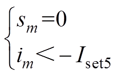 (11)
(11)
式中, 为考虑晶闸管漏电流的阈值。
在PSCAD/EMTDC中建立某直流模型[7],验证所提阀电流计算方法的有效性。根据2.1.2小节取值原则考虑[15, 18-19, 21],结合晶闸管的元件技术参数及直流工程报告查询,设置直流模型阀电流计算的阀状态判别阈值为: ;
; ;
;
 ;
; ;
; ,
, ;
; ;
; 。
。
为绘图标识方便,根据阀侧电流时序特征在旁通回路运行时修正阀导通状态计算得到的阀电流,简称为“导通修正”;在导通修正的基础上,利用阀的单向导向性对旁通回路退出运行时校正阀关断状态计算得到的阀电流,简称为“关断校正”。
考虑到逆变器换流母线三相故障,可能最多出现三相旁通的情况,换流器运行状态最复杂。以逆变器换流母线三相交流故障为例展开分析。本文基于交流电流的极性状态、“导通修正”、“关断校正”的阀状态与实际阀状态的对比如图6所示。

图6 交直流电流和阀状态
Fig.6 Waveforms of AC-DC currents and valve state
由图6可见,阀导通状态的修正均出现在换流器形成旁通回路阶段,阀关断状态的校正均出现在旁通阀对的退出阶段。与极性值相比,“导通修正”的阀电流计算值、“关断校正”的阀电流计算值、阀电流实际值如图7所示。图7中阴影部分表示仿真中涉及的旁通状态。
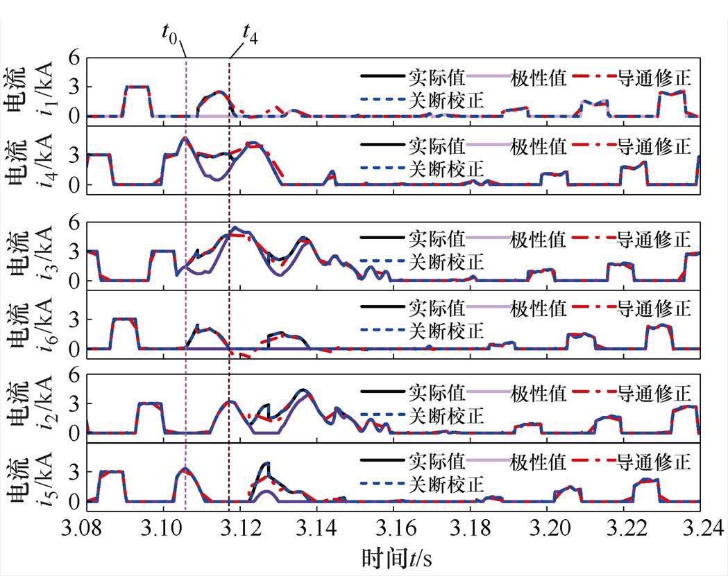
图7 三相故障下阀电流实际值与计算值的对比
Fig.7 A comparison of the actual values and calculated values under the ABC fault
从图7可知,正常运行时,交流电流的极性值、“导通修正”的阀电流计算值、“关断校正”的阀电流计算值均等于阀电流的实际值。表明所提方案在计算正常运行阀电流时是有效的。在t0时刻换流器形成旁通运行时,交流电流的极性值与阀电流实际值有差异,而“导通修正”的阀电流计算值等于阀电流实际值,表明所提基于阀状态导通修正方案可以计算换流器的旁通运行状态。但是,从时刻t4开始,“导通修正”的计算值与实际值出现差异。这是由于旁通阀对中有一个阀从导通状态变为关断状态时,阀关断状态会受交流电流判据的影响出现误判。即“导通修正”的计算方案解决了换相失败后出现旁通运行时的阀导通状态的判别,但不能实现针对旁通阀对退出运行时的阀关断状态的判别。因此,在“导通修正”的基础上,利用对阀单向导电性的约束,得到的基于“关断校正”的阀电流计算值等于阀电流实际值,解决了旁通阀对退出运行时阀关闭状态的校正问题。
为验证该方法的普适性,设置不同的故障条件观察其有效性。众多故障因素下,故障类型和故障时刻对换流器的影响较大[23],因此对两种故障因素下的计算性能进行分析。采用单一变量的控制方法,在同一故障时刻下改变故障类型和同一故障类型下改变故障时刻设置故障。与极性值相比,“导通修正”的阀电流计算值、“关断校正”的阀电流计算值、阀电流实际值如图8~图10所示。
图8~图10仿真结果显示:在不同的故障条件下,当换流器出现旁通运行时,“导通修正”的阀电流计算值等于阀电流实际值;当换流器旁通运行退出时,“关断校正”的阀电流计算值均等于阀电流的实际值。仿真结果表明:即使阀状态不同、旁通组数不同,所提阀电流计算方案在换相失败及其故障恢复的暂态过程中均可准确且有效地计算出阀电流。
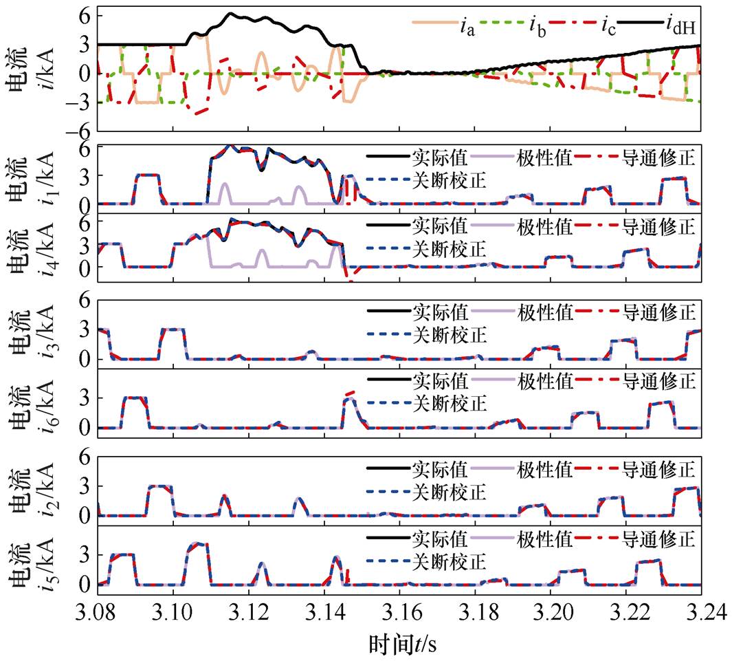
图8 单相故障下阀电流实际值与计算值的对比
Fig.8 Valve currents of the actual values and calculated ones under the Ag fault
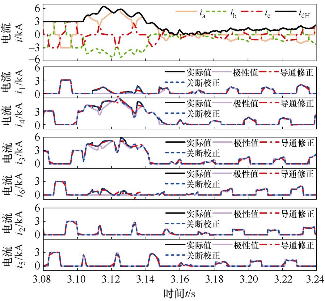
图9 相间故障下阀电流实际值与计算值的对比
Fig.9 Valve currents of the actual values and calculated ones under the AB fault
为验证本文所提的阀电流计算方法在实际工程中的有效性,取某工程包含了正常运行、换相失败暂态过程和故障恢复过程的录波数据,如图11的第一幅图所示。基于所提方案阀电流计算值与交流电流的极性值的对比结果如图11所示。
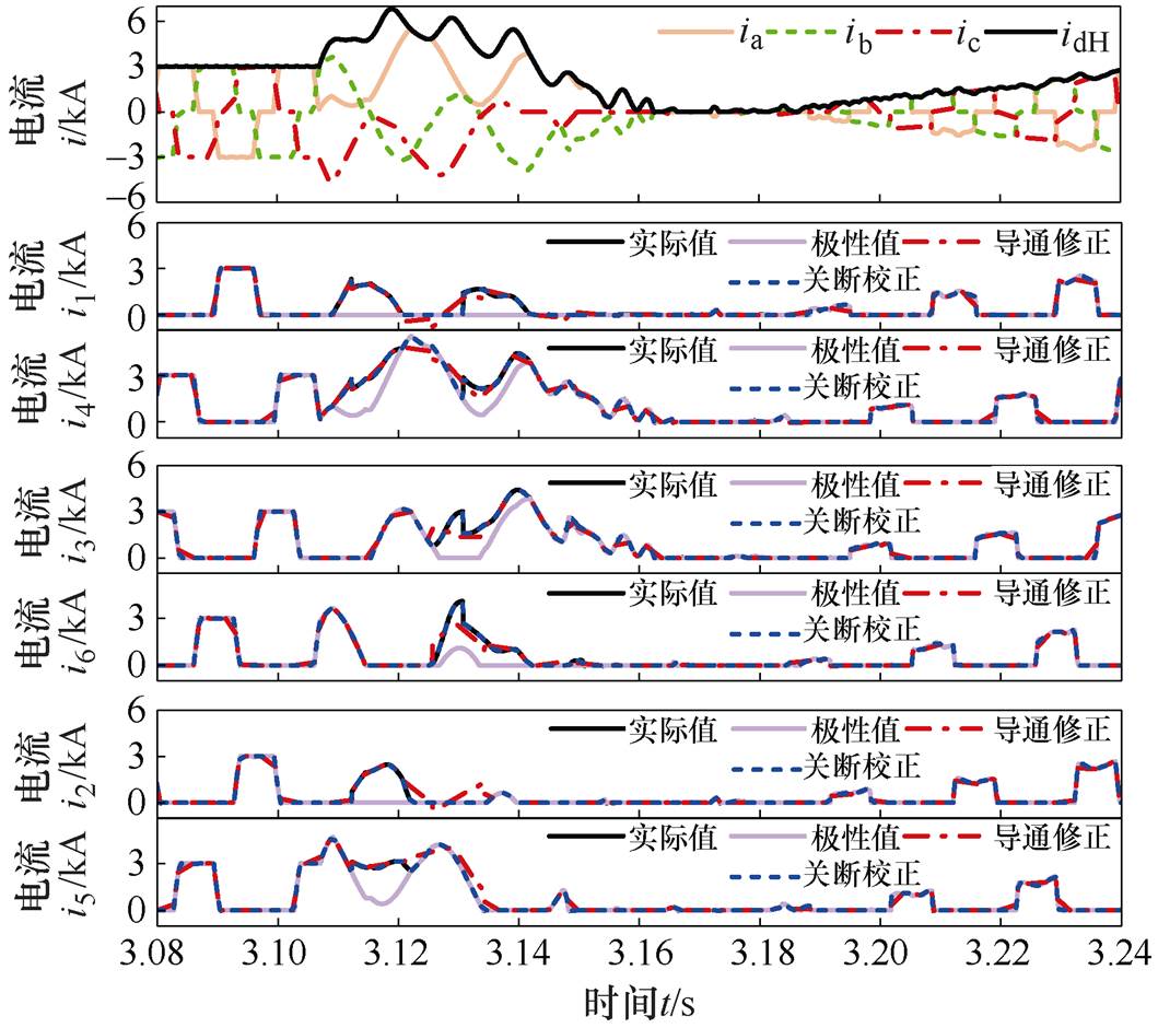
图10 改变故障时刻时阀电流实际值与计算值的对比
Fig.10 Valve currents of the actual values and calculated ones when change the fault moment
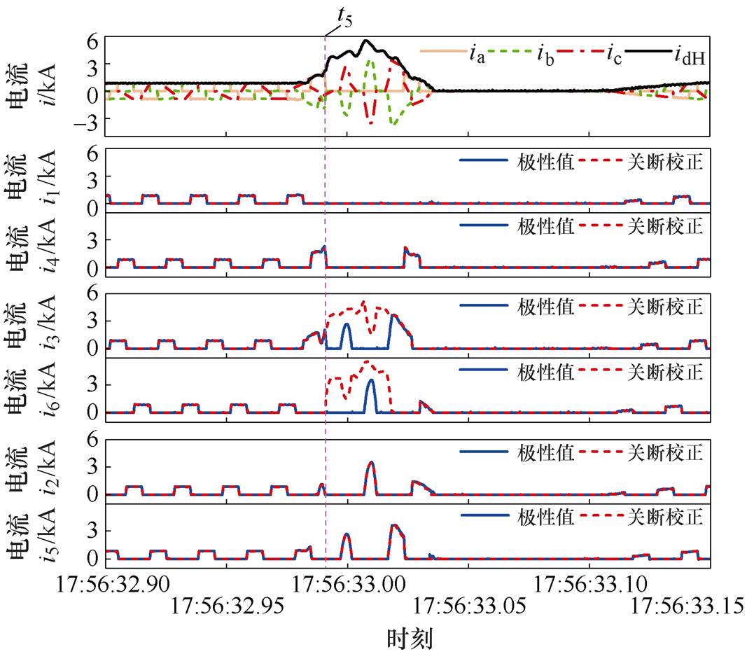
图11 录波再现时的阀电流计算值
Fig.11 Valve current calculated under the field record wave
图11可知,在录波再现的全过程中,根据交直流电流的特征可以判断在t5时刻b相形成旁通。b相旁通时,基于本文所提阀电流计算方法能够求解得到阀电流,验证了本文所提方法能够判别阀状态、反映旁通组情况并计算阀电流的有效性。
本文分析了暂态过程中,换流器旁通回路运行时阀导通状态的判别和换流器旁通回路退出运行的阀关断状态的判别是三相交流电流的极性特征和阀电流产生差异的主要原因。提出了一种阀电流计算方案,主要结论如下:
1)提出利用阀侧交直流电流的幅值特征判别阀状态。根据电流的时序特征,确定正在导通的阀是否会被关断、正在关断的阀是否会被导通。阀状态实时的连续判别,提高了阀电流计算的可靠性。
2)根据多相旁通组间的并联电路关系增补的旁通回路方程,解决了关联方程在计算阀电流时因个数不足导致不可解的问题。
3)利用旁通时的电流时序特征对阀导通状态进行修正,利用阀的单向导电性对阀关断状态进行实时校正,避免因误判阀状态而导致阀电流的不正确计算。
4)仿真结果和录波数据表明:不同的阀状态和旁通组数下,所提方法均能在换相失败及其故障恢复暂态过程中计算出阀电流。
本文提出的阀电流计算的方法,是提升换流器能观性的核心关键技术。所提方法有利于推动现有传统高压直流电网的换流器运行状态的在线检测,为换流器的保护控制优化提供了基础数据。
参考文献
[1] 高本锋, 王刚, 刘毅, 等. LCC-HVDC送端电网等值方案研究[J]. 电工技术学报, 2021, 36(15): 3250- 3263, 3271.
Gao Benfeng, Wang Gang, Liu Yi, et al. Study on equivalence method of AC system in sending-end of LCC-HVDC[J]. Transactions of China Electrotech- nical Society, 2021, 36(15): 3250-3263, 3271.
[2] 丁平, 安宁, 赵敏, 等. 一种实用的电压源型换流器及直流电网机电暂态建模方法[J]. 电工技术学报, 2017, 32(10): 69-76.
Ding Ping, An Ning, Zhao Min, et al. A practical modeling method of VSC-HVDC and DC-grid electromechanical transient[J]. Transactions of China Electrotechnical Society, 2017, 32(10): 69-76.
[3] Wang Juanjuan, Huang Menghua, Fu Chuang, et al. A new recovery strategy of HVDC system during AC faults[J]. IEEE Transactions on Power Delivery, 2019, 34(2): 486-495.
[4] 张波. 电力电子学亟待解决的若干基础问题探讨[J]. 电工技术学报, 2006, 21(3): 24-35.
Zhang Bo. Discussion on several fundamental pro- blems necessary to be solved in power electronics[J]. Transactions of China Electrotechnical Society, 2006, 21(3): 24-35.
[5] 周亮, 张蕴馨, 林志光, 等. 交流系统故障下高压直流输电晶闸管触发监测单元储能方式[J]. 电力系统自动化, 2019, 43(9): 160-164.
Zhou Liang, Zhang Yunxin, Lin Zhiguang, et al. Energy storage method of thyristor triggering and monitoring unit for HVDC transmission system with fault of AC system[J]. Automation of Electric Power Systems, 2019, 43(9): 160-164.
[6] 王振, 刘坤, 国建宝, 等. 电控与光控晶闸管换流阀触发机理对比分析研究[J]. 电力电子技术, 2019, 53(3): 74-77.
Wang Zhen, Liu Kun, Guo Jianbao, et al. Com- parative analysis of trigger mechanism for electric and light converter valve[J]. Power Electronics, 2019, 53(3): 74-77.
[7] Yin Shanshan, Li Xiaohua, Li Hao, et al. Novel detection scheme for commutation failure based on virtual blocking state[J]. International Journal of Electrical Power & Energy Systems, 2022, 137: 107789.
[8] 贺杨烊, 郑晓冬, 邰能灵, 等. 交直流混联电网LCC-HVDC换流器建模方法综述[J]. 中国电机工程学报, 2019, 39(11): 3119-3130.
He Yangyang, Zheng Xiaodong, Tai Nengling, et al. A review of modeling methods for LCC-HVDC converter in AC/DC hybrid power grid[J]. Pro- ceedings of the CSEE, 2019, 39(11): 3119-3130.
[9] 蔡洋, 郭文勇, 赵闯, 等. 模块化多电平换流器直流故障过电流精确计算与分析[J]. 电工技术学报, 2021, 36(7): 1526-1536.
Cai Yang, Guo Wenyong, Zhao Chuang, et al. The accurate calculation and analysis of overcurrent under modular multilevel converter DC fault[J]. Transa- ctions of China Electrotechnical Society, 2021, 36(7): 1526-1536.
[10] 郭春义, 宁琳如, 王虹富, 等. 基于开关函数的LCC-HVDC换流站动态模型及小干扰稳定性[J]. 电网技术, 2017, 41(12): 3862-3868.
Guo Chunyi, Ning Linru, Wang Hongfu, et al. Switching-function based dynamic model of LCC- HVDC station and small signal stability analysis[J]. Power System Technology, 2017, 41(12): 3862- 3868.
[11] 严鋆, 王金全, 陈颖, 等. 基于开关函数的脉冲功率负载大信号模型研究[J]. 电工技术学报, 2020, 35(16): 3509-3517.
Yan Jun, Wang Jinquan, Chen Ying, et al. Study on large-signal model for pulsed power load based on switching functions[J]. Transactions of China Electro- technical Society, 2020, 35(16): 3509-3517.
[12] 汪燕, 姚蜀军, 林芝茂, 等. 一种基于多频段动态相量的LCC换流器电磁暂态建模方法研究[J]. 中国电机工程学报, 2020, 40(17): 5644-5652.
Wang Yan, Yao Shujun, Lin Zhimao, et al. A modeling method for LCC electromagnetic transient simulation based on multi frequency band dynamic phasor[J]. Proceedings of the CSEE, 2020, 40(17): 5644-5652.
[13] Liu Chongru, Zhao Yunhao, Wang Chao, et al. Superposition feature of the switching functions for the dynamic phasor model of the converters under commutation failure[J]. IET Generation, Trans- mission & Distribution, 2015, 9(12): 1448-1454.
[14] 戚庆茹, 焦连伟, 严正, 等. 高压直流输电动态相量建模与仿真[J]. 中国电机工程学报, 2003, 23(12): 28-32.
Qi Qingru, Jiao Lianwei, Yan Zheng, et al. Modeling and simulation of HVDC with dynamic phasors[J]. Proceedings of the CSEE, 2003, 23(12): 28-32.
[15] 王兆安, 刘进军. 电力电子技术[M]. 5版. 北京: 机械工业出版社, 2009.
[16] ABB Power System.Loss calculation on thyristor valve for HVDC[R]. Germany: ABB Power System, 1999.
[17] 李崇涛, 林啸, 赵勇, 等. 高压直流输电系统暂态过程的解析解法(一): 数学模型[J]. 电网技术, 2017, 41(1): 1-7.
Li Chongtao, Lin Xiao, Zhao Yong, et al. An analytical solution for transient process of HVDC transmission system part 1-mathematical model[J]. Power System Technology, 2017, 41(1): 1-7.
[18] 许汉平, 杨炜晨, 张东寅, 等. 考虑换相失败相互影响的多馈入高压直流系统换相失败判断方法[J]. 电工技术学报, 2020, 35(8): 1776-1786.
Xu Hanping, Yang Weichen, Zhang Dongyin, et al. Commutation failure judgment method for multi- infeed HVDC systems considering the interaction of commutation failures[J]. Transactions of China Elec- trotechnical Society, 2020, 35(8): 1776-1786.
[19] Zhao Yufeng, Ma Jing, Jiang Tong, et al. Com- mutation failure prediction method based on characteristic of accumulated energy in inverter[J]. International Journal of Electrical Power & Energy Systems, 2021, 133: 107311.
[20] Wei Zhanhong. A criterion for accurate identification of commutation failure in HVDC systems[J]. Electric Power Systems Research, 2020, 184: 106338.
[21] 孔祥平, 李鹏, 阮思烨, 等. 实景替代式特高压直流保护系统现场性能测试方案[J]. 电力系统自动化, 2019, 43(13): 139-146.
Kong Xiangping, Li Peng, Ruan Siye, et al. Live- action substitution based field performance test scheme for UHVDC protection system[J]. Automation of Electric Power Systems, 2019, 43(13): 139-146.
[22] 李晓华, 殷珊珊, 李洁雯, 等. 基于阀侧电流时序特征的换流阀状态与阀电流的求解方法: CN112769132A[P]. 2021-05-07.
[23] 蔡泽祥, 杨欢欢, 余超耘, 等. 考虑时空离散性的高压直流输电系统换相失败评估方法[J]. 华南理工大学学报(自然科学版), 2017, 45(7): 33-40.
Cai Zexiang, Yang Huanhuan, Yu Chaoyun, et al. A method to assess commutation failure of HVDC systems taking space-time discreteness into con- sideration[J]. Journal of South China University of Technology (Natural Science Edition), 2017, 45(7): 33-40.
Abstract As the essential element for electronic power conversion, the line-commutated converter is the core equipment in high-voltage direct current (HVDC) transmission systems. The safety of the converter equipment is critical to the stable operation of an AC/DC hybrid power grid after AC faults. When commutation failure occurs in the converter, the valve that experiences commutation failure is conducted for a long time with a high current, which may cause the valve to be damaged or burned, thereby exacerbating the security complexity between the converter and the grid. The valve current is a direct manifestation of the thyristor converter operating state. Recently, the existing studies on the converter thyristor valve current are mainly conducted through converter modeling, which involves the calculation of thyristor valve current. However, this method of valve current calculation must first assume the valve state. Nevertheless, especially during commutation failure and fault recovery, the assumed valve state may be wrong, resulting in incorrect valve currents. Therefore, a real-time calculation method of the valve current is proposed based on the temporal features of the converter terminal AC and DC currents. The protection and control capabilities of the equipment are optimized, and the reliability of the converter technology is improved by learning the accurate calculation of the thyristor valve current.
According to the circuit constraints of the converter topology, the vector sum of the three-phase AC current is equal to 0 under the condition that there is no fault inside the converter. The KCL equations of the five nodes in the converter topology are combined to establish the correlation equation between the converter terminal current and the thyristor valve current. In order to determine the current distribution, the valve state should be introduced based on the topological equation. Firstly, the polarity characteristics of the converter terminal AC current and temporal features between the valves are utilized to estimate the valve state. When the bypass group occurs, the AC and DC currents of the converter are isolated, and the polarity characteristics of the three-phase AC current cannot estimate the valve conducting state of the bypass pair. The valve conducting state of the bypass group is necessary to revise. Secondly, the bypass number of the converter is calculated based on the valve state, the parallel relationship between the bypass phases during multiphase bypasses is established, and the supplementary bypass loop equation is constructed. Finally, the supplementary bypass loop equation and the associated equation are combined to calculate the thyristor valve current. When the thyristor valve current is a negative value, the blocking state of the valve is corrected in real-time, and the valve current is recalculated.
The simulation results show that the calculated value of the thyristor valve current before the converter bypass equals the actual value. Scheme 1, based on revising the valve conducting state, can calculate the thyristor valve current in the bypass operating state of the converter. However, starting from the moment the converter exits the bypass operation, the thyristor valve current calculated by scheme 1 appears to be different from the actual value, indicating that the calculated value is incorrect. Scheme 1 addresses the conduction judgment of bypass operation after commutation failure, but the valve blocking state needs to be corrected after commutation failure. According to scheme 1, scheme 2, based on correcting the valve blocking state, addresses the correction of the valve blocking state after commutation failure by constraining the unidirectional conductance characteristics of the valve. Under different valve states and bypass groups, the proposed real-time calculation method can accurately calculate the valve current in the transient process of commutation failure and its fault recovery, which verifies the effectiveness and reliability of the valve current calculation method.
keywords:Valve current, valve-side current, temporal features, valve state estimation, bypass loop equation, valve blocking state correction
DOI: 10.19595/j.cnki.1000-6753.tces.220101
中图分类号:TM771
河南省重点研发与推广专项资助项目(232102241042)。
收稿日期 2022-01-08
改稿日期 2022-08-03
李晓华 女,1975年生,教授,博士生导师,研究方向为电力系统故障分析和继电保护、高压直流输电运行。E-mail: eplxh@scut.edu.cn
殷珊珊 女,1989年生,博士,讲师,研究方向为高压直流输电系统故障分析和保护。E-mail: yss1041529800@126.com(通信作者)
(编辑 郭丽军)