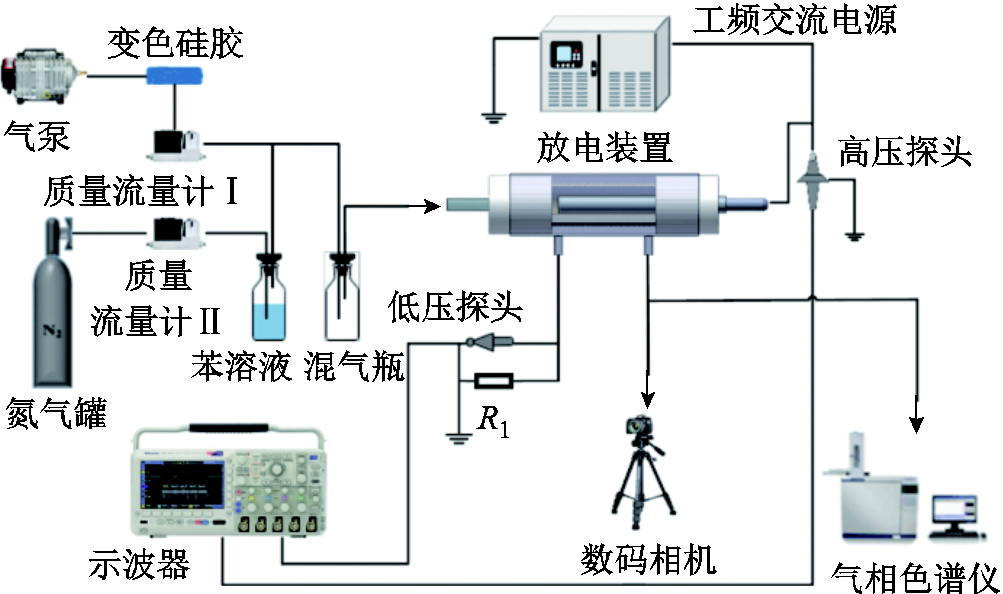
图1 实验系统整体结构
Fig.1 Schematic of experimental system
摘要 微放电可在小的空间中产生高密度等离子体,有利于气体污染物的高效处理。该文研究了电极结构及电极形状对多孔陶瓷孔内微放电特性及苯降解的影响。结果表明:在相同外加电压条件下,与二电极结构相比,三电极结构可生成更多的丝状放电通道,峰-峰电荷Qpk-pk提高了3.2倍,放电电荷Qd提高了4.4倍,放电功率从0.8W提高到8.6W,苯降解效率提高了35.1%;网高压电极结构相比于弹簧电极,能够增加有效放电面积并增强放电强度,放电功率相较于弹簧电极构型提高约4W,丝状放电通道能够充满放电空间,显著提高苯降解效率。
关键词:介质阻挡放电 微放电 电极构型 苯降解
介质阻挡放电(Dielectric Barrier Discharge, DBD)是将绝缘介质放置于放电空间内的一种放电形式[1]。绝缘介质抑制放电向弧光或火花放电的转变,能够在常温常压下产生大量微放电通道,有利于稳定地生成等离子体[2],在杀菌消毒[3]、臭氧合成[4-6]、材料表面改性[7-8]、气流控制[9-10]、环境保护[11-15]等领域得到了广泛关注。
微放电是放电被限制在一个有限空间范围内的气体放电形式,因其具有高电子密度等特性而被广泛关注[16]。K. Hensel等研究了由直流高压产生的多孔材料中微放电的形成,放电从表面放电延伸至陶瓷中,并且在材料内部观察到微放电[17-18]。D. B. Nguyen等成功地在多孔蜂窝陶瓷反应器中产生等离子体,研究了体系内臭氧和氮氧化物的产生,发现该装置在降解有机化合物等方面具有一定优势[19]。此外,DBD装置中电极结构对于放电特性和活性物质产生特性具有较大的影响[20-21]。李清泉等研究了网眼大小不同的丝网、不同结构形式的极板结构对介质阻挡放电的影响,发现采用针-板电极时容易形成稳定的放电[22]。商克峰等研究了阵列针电极、网电极、平板电极构型对DBD特性、臭氧生成特性的影响,发现网孔尺寸为0.5mm×0.5mm的网电极放电时生成的臭氧质量浓度最高[23]。然而目前鲜有研究关注如何增强孔内微放电的强度用于提高活性物质生成,进而促进污染物分解。本文研究高压电极构型对多孔陶瓷孔内微放电特性的影响,并以苯作为目标物,考察了多孔陶瓷微放电等离子体降解挥发性有机化合物(Volatile Organic Compounds, VOCs)的效果。
实验系统整体结构如图1所示,主要由放电装置、工频交流电源、电气参数测试仪器(高压探头、低压探头和示波器)、配气系统、气相色谱仪等构成[9]。

图1 实验系统整体结构
Fig.1 Schematic of experimental system
多孔陶瓷DBD结构放电装置如图2所示,二电极DBD装置缺少地电极Ⅱ,其中石英玻璃(厚1mm,外径9mm)作为介质,不锈钢金属棒(外径7mm)作为地电极置于石英介质管内,304不锈钢编制套网(10目)作为高压电极放置于多孔陶瓷管外,放电区域长50mm。多孔陶瓷管内径为11mm,外径为20mm,孔径为60μm,孔隙率为30%。三电极DBD装置是在二电极结构基础上,将铝箔(厚0.8mm)附着于最外层石英玻璃管(内径30mm,壁厚1mm)上作为地电极Ⅱ,高压电极分别采用金属网和不同节距的不锈钢弹簧(弹簧线径1mm,节距t为4mm和9mm)。
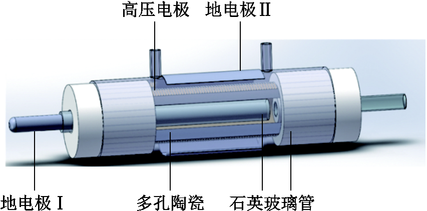
图2 多孔陶瓷DBD结构放电装置
Fig.2 DBD device with porous ceramics
放电实验在室温、正常大气压条件下进行。放电装置由工频交流高压电源(0~60kV,50Hz)供电,采用电压探头(Tektronix P6015A)测量外加激励电压,并用电压探头(Tektronix P2220)测量监测采样电容(1μF)两端的电压信号,以得到Lissajous图形;采用电压探头(Tektronix TPPO200)测量采样电阻(100Ω)两端的电压信号得到放电电流,由数字示波器(Tektronix TDS2024)监测电压、电流信号;放电功率、单个放电周期内的峰-峰电荷量Qpk-pk和放电电荷量Qd通过Lissajous图形法计算[24],等效总电容Ccell、介质等效电容Cd由Lissajous图形获得,气隙等效电容Cg为
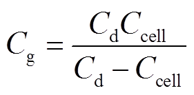 (1)
(1)
而气隙电压ug和介质电压ud的关系[25]为
![]() (2)
(2)
式中,Cm和um分别为采样电容值和采样电容两端的电压,本实验中Cm为1μF;ua为外加电压。
放电图像使用Canon EOS 80D相机拍摄。模拟废气中苯的浓度采用气相色谱仪(Shimadzu GC—2010)测试,其降解效率η(%)和能量效率EY[g/(kW·h)]分别为
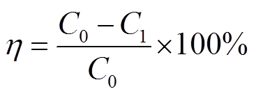 (3)
(3)
 (4)
(4)
式中,C0和C1分别为反应器进出口苯浓度,10-4%;M为苯的摩尔质量,M=78.11g/mol;V为气体流量,L/min;P为放电功率,W。
二电极和三电极结构的电压u和电流i的波形如图3所示。实验中放电长度为5cm,干燥空气流速为1L/min,外加电压幅值为18kV,频率为50Hz。由图3可以看出,放电是典型的丝状DBD模式;通过对比二电极系统和三电极系统的电压电流波形,发现三电极系统中丝状电流脉冲通道数目明显增加,且电流幅值显著增强,说明增加电极数量可以有效提高放电强度。相比于二电极结构,在正半周期内,三电极结构除产生正向电流细丝外,还存在大量负向电流细丝,表明三电极的放电空间可以扩展到高压电极到地电极Ⅰ和高压电极到地电极Ⅱ两部分区域,导致三电极系统结构比二电极结构产生更多数量的电流脉冲。外加电压18kV条件下的放电图像如图4所示,可以明显看出三电极结构放电时的放电强度远大于二电极结构,高压电极与地电极Ⅱ之间的空间内充满放电细丝,这也是三电极结构电流脉冲通道数量增加的原因。
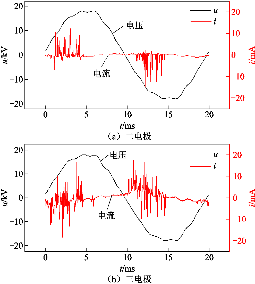
图3 二电极和三电极结构的电压电流波形
Fig.3 Voltage and current waveforms of double and triple electrodes
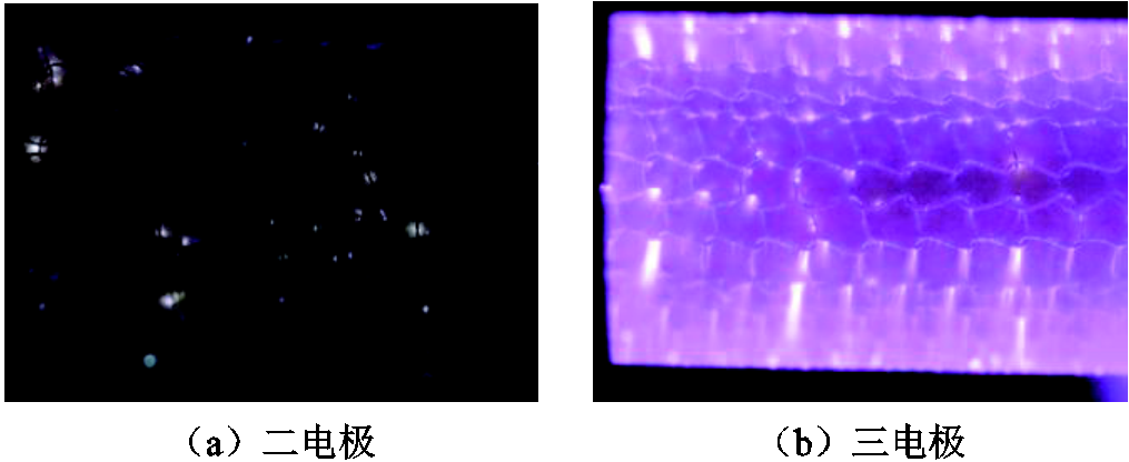
图4 二电极和三电极的放电图像(18kV, f/2.8, ISO-12 800, 2″)
Fig.4 Discharge pictures of double and triple electrodes (18kV, f/2.8, ISO-12 800, 2″)
不同电极结构的Lissajous图形如图5所示。二电极DBD结构的Lissajous图形为标准的平行四边形,但是三电极结构的Lissajous图形由扁平的平行四边形变为面积更大的近似椭圆形。Lissajous图形的左右对边和上下对边的斜率分别对应于放电发生和熄灭的有效电容,由于放电阶段电源向介质等效电容充电,故放电阶段对应的有效电容为介质等效电容,而熄灭阶段对应的有效电容为介质等效电容与气隙等效电容串联时的总电容[26]。
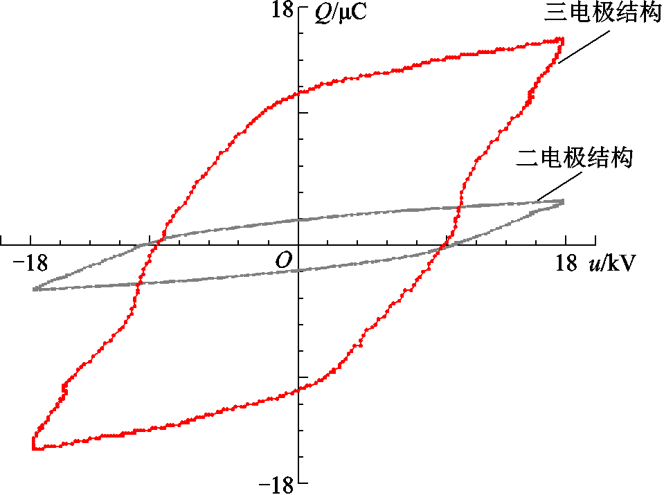
图5 二电极和三电极结构的Lissajous图形
Fig.5 Lissajous figures of double and triple electrodes
根据Lissajous图形计算得到的介质等效电容和总电容参数表明,当外加峰值电压为18kV时,二电极结构的气隙等效电容Cg(0.17nF)与三电极结构的气隙等效电容Cg(0.24nF)相当,但是三电极结构装置的介质等效电容Cd(1.7nF)远大于二电极结构的Cd(0.42nF),为二电极结构的3.5倍。在介质阻挡放电中,介质材料的介电常数εd与厚度ld不变,介质等效电容与放电有效面积S成正比[27],即
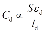 (5)
(5)
因此,在增加一个电极后,放电区域内放电更加强烈,放电细丝通道相应增加(如图2所示),导致放电有效面积增大,介质等效电容增大。同时,根据式(2)可知,相同外加电压下,三电极结构的气隙电压ug较高,放电间隙内电场强度大,这可能是导致三电极结构的电流脉冲幅值与数量较多的原因。
当外加峰值电压为18kV,三电极结构中高压电极分别为网电极和弹簧电极(节距t=4mm和t=9mm)时的电压、电流波形如图6所示,放电图像如图7所示。从图6可以看出,高压电极为网电极时,电流脉冲数量与峰值都远大于弹簧电极的情况,在正半周期内,网电极结构的负向电流脉冲细丝数目明显增多。当弹簧电极作为高压电极时,节距较小的电极测得丝状电流脉冲相对更加强烈。从图7的放电图像可以看出,网电极结构的放电强度较高,相较于弹簧结构,其放电电流细丝能够充满放电空间。上述结果表明,放电电极的表面积越大,越有利于增多放电点位进而提高丝状脉冲放电通道。
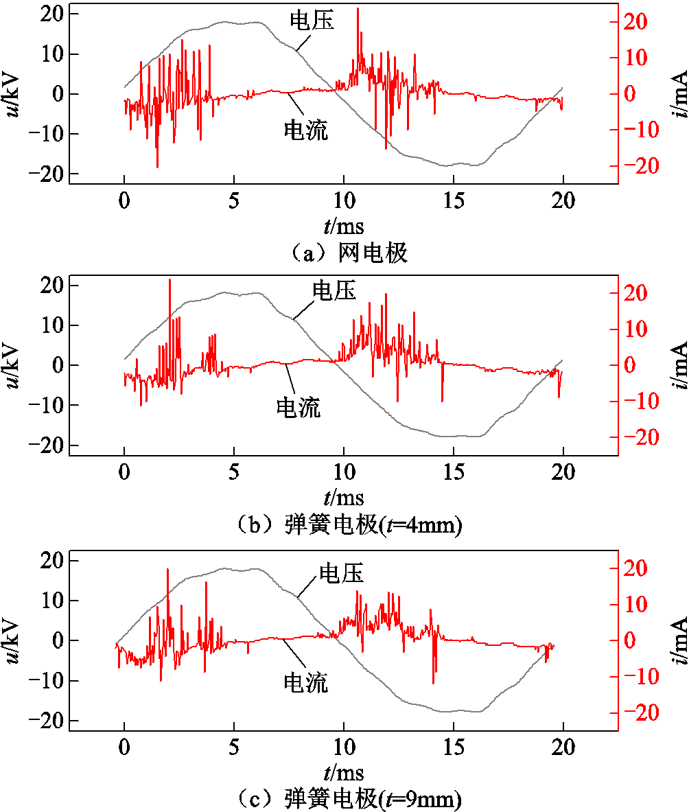
图6 不同高压电极下的电压电流波形
Fig.6 Voltage and current waveforms of different high voltage electrodes

图7 不同高压电极下的放电图像(18kV, f/2.8, ISO-12 800, 0.5″)
Fig.7 Discharge pictures of different high voltage electrodes(18kV, f/2.8, ISO-12 800, 0.5″)
同一外加电压条件下,不同电极结构的Lissajous图形如图8所示。从图8可以看出,当高压电极结构从网电极过渡到弹簧电极,并随着弹簧电极节距的增大,Lissajous图形的形状逐渐趋于扁平。根据式(1)计算不同电极构型下等效电容参数可知,在相同外加峰值电压下,节距为4mm的弹簧电极介质电容Cd(1.46nF)与气隙电容Cg(0.2nF)略大于节距为9mm的弹簧电极结构(Cd=1.14nF, Cg=0.16nF),而网电极结构装置的介质电容Cd(1.7nF)与气隙电容Cg(0.24nF)均最大。由前文分析可知,等效电容大小反映放电有效面积,等效电容越大,放电通道扩散越大。因此可见网高压电极结构有利于放电细丝扩散,能够有效提高放电有效面积。同时根据式(2)可知,不同电极结构间的气隙电压ug相差不大,而网高压电极可以有效增加放电面积和放电点位,导致丝状放电通道的数目和强度增加。
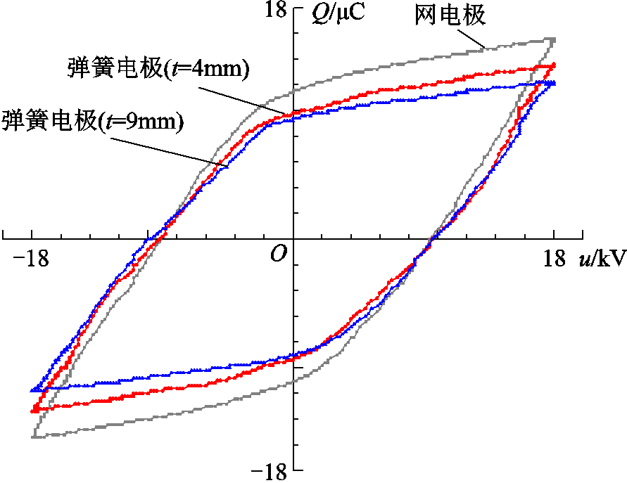
图8 不同高压电极下的Lissajous图形
Fig.8 Lissajous figures of different high voltage electrodes
不同电极数量条件下的放电功率如图9a所示,可以看出功率随着外加峰值电压增大而增加,同时三电极结构装置的放电功率均大于二电极结构,在外加峰值电压为14kV时,二电极结构装置的放电功率仅为0.8W,而三电极结构装置的放电功率增加到8.6W。图9b考察不同电极数量条件下的电荷特性,包括峰-峰电荷Qpk-pk和放电电荷Qd。结果显示,当外加峰值电压为18 kV,空气流量为1L/min时,计算所得三电极结构的Qpk-pk为28μC,是二电极结构的3.2倍,同时放电电荷约为二电极结构的4.4倍,能够看出三电极结构装置可以有效提高放电区域电荷量。这是因为增加地电极数量后,放电间隙增加,多孔陶瓷管与外层石英玻璃间的空气可以被电离,从而产生更多的带电粒子,这也解释了三电极结构装置电流脉冲数量远大于二电极结构的实验现象。
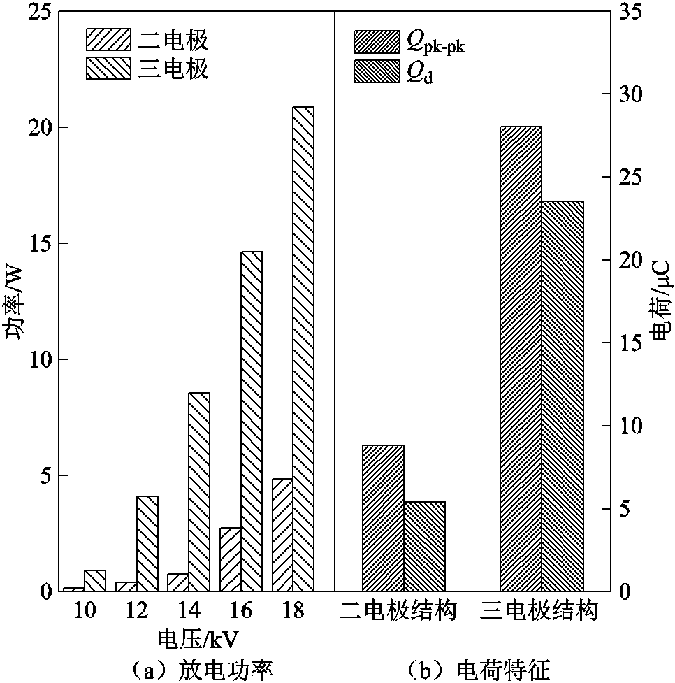
图9 电极数量对放电功率和电荷特征的影响
Fig.9 Effect of electrode quantity on the discharge power and charge characteristics
三电极结构装置中高压电极构型对放电功率及电荷特性的影响如图10所示。对比不同外加峰值电压条件下网电极、弹簧电极(t=4mm和t=9mm)的放电功率发现,当峰值电压小于14kV时,不同节距的弹簧电极结构的放电功率相差不大,但是都小于网电极结构的放电功率;随着外加峰值电压继续提高,不同结构电极间的放电功率差值逐渐增加,其中网电极结构的放电功率始终远高于弹簧结构电极。结合电极构型对等效电容的影响结果可以发现,这可能与网结构电极的有效放电面积有关。网电极结构拥有最大的有效放电面积,可以产生更多的放电通道,导致放电电流脉冲数量增加(如图6),以及放电功率的有效提高。从图10b中可以看出电极构型对电荷特征的影响,其中,相同外加峰值电压条件下,网电极结构的峰-峰电荷Qpk-pk和放电电荷Qd均最大,这与放电功率变化趋势一致,进一步说明网电极结构有利于电荷的积累。
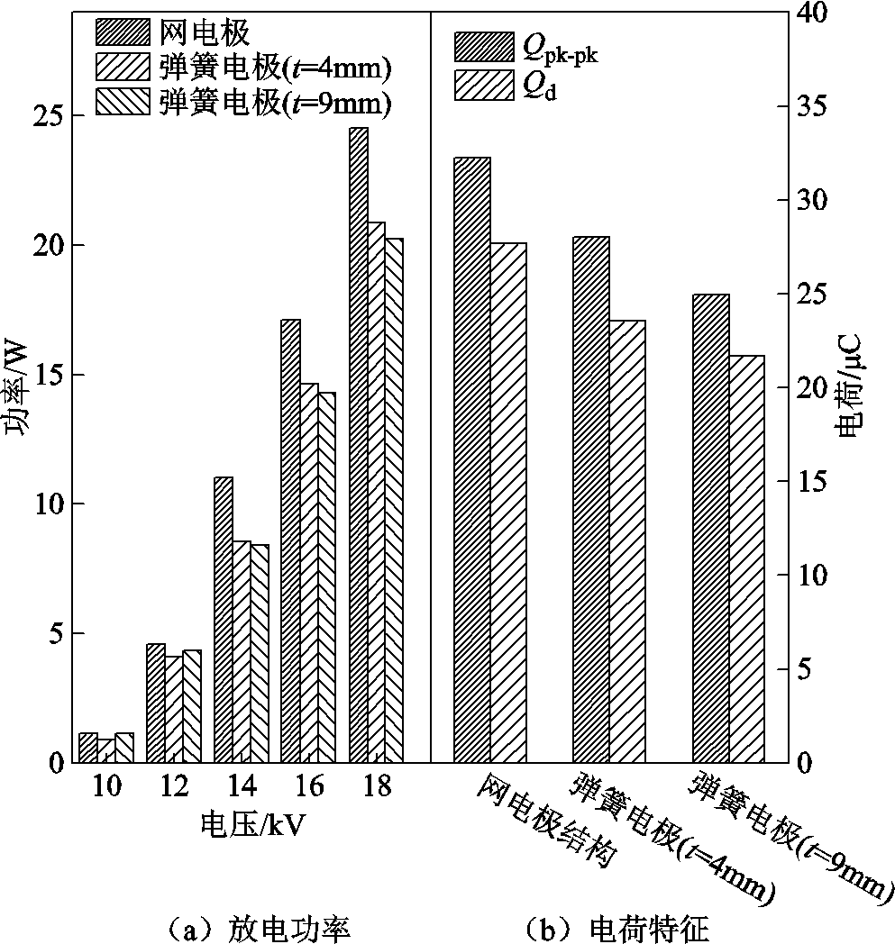
图10 电极构型对放电功率和电荷特征的影响
Fig.10 Effect of electrode configuration on the discharge power and charge characteristics
不同电极构型对苯降解效率的影响如图11a所示,其中苯初始浓度为150×10-4%,气体流速为50mL/min。从图11a中可以看出,随着外加峰值电压的增大,苯降解效率不断提高,这与放电功率变化趋势一致。当外加电压14kV时,计算得出二电极结构的苯降解能量效率为0.22g/(kW.h),三电极结构的苯降解能量效率为0.16g/(kW.h),虽然降解效率的提高会导致能量效率轻微下降,但是三电极结构的苯降解效率为49.5%,比二电极结构提高了35.1%,说明三电极结构有利于苯的降解。
高压电极构型对苯降解效率的影响如图11b所示,其中苯初始浓度为150×10-4%,气体流速为100mL/min。从图11b中可知,当外加电压16kV时,网高压电极结构的苯降解效率(50.9%)与4mm节距的弹簧电极结构(50.6%)相差不大;而随着外加峰值电压逐渐增大,网高压电极与4mm节距的弹簧电极结构的苯降解效率始终高于9mm节距的弹簧电极结构,这与放电功率和电荷特征变化趋势一致。在外加峰值电压为12kV时,计算得到网高压电极的能量效率为0.25g/(kW.h),4mm和9mm节距的弹簧高压电极的能量效率分别为0.29g/(kW.h)和0.19g/(kW.h),说明4mm弹簧电极的能量效率略高于其他两种电极结构。
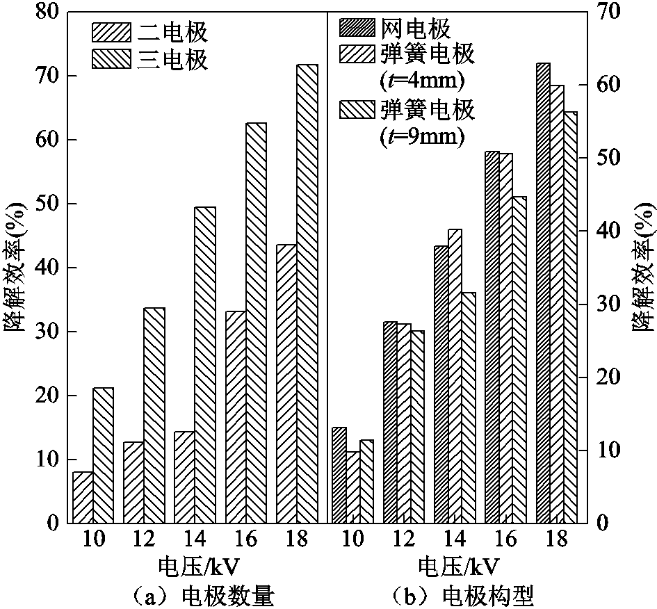
图11 电极数量和构型对苯降解效率的影响
Fig.11 Effect of electrode quantity and configuration on the benzene degradation rate
综上所述,增加地电极及采用网电极或节距更小的弹簧电极可以有效地提高放电有效面积和放电电荷,导致产生更多的活性粒子及自由电子,从而增加碰撞苯分子的概率,提高苯降解效率。提高放电功率在提高苯降解效率的同时,会导致能量效率轻微下降,因此应综合考虑,选择最优的电极结构。
1)相较于二电极结构,三电极结构能够有效增加放电空间,产生更多的放电电流脉冲,提高峰-峰电荷Qpk-pk和放电电荷Qd,放电功率更高。
2)在三种不同电极构型(网电极、4mm节距的弹簧电极和9mm节距的弹簧电极)中,网电极结构装置的峰-峰电荷和放电电荷均最大。当外加峰值电压大于12kV时,网电极的放电功率远大于弹簧电极。
3)外加电压相同时,三电极结构及网电极构型提高了放电面积,显著提高了苯降解效率。
参考文献
[1] 王新新. 介质阻挡放电及其应用[J]. 高电压技术, 2009, 34(1): 1-11.
Wang Xinxin. Dielectric barrier discharge and its applications[J]. High Voltage Engineering, 2009, 34(1): 1-11.
[2] 王燕, 赵艳辉, 白希尧, 等. DBD等离子体及其应用技术的发展[J]. 自然杂志, 2002, 24(5): 277-282.
Wang Yan, Zhao Yanhui, Bai Xiyao, et al. DBD plasma and the development of its application[J]. Nature Magazine, 2002, 24(5): 277-282.
[3] 夏文杰, 刘定新. Ar等离子体射流处理乙醇水溶液的放电特性及灭菌效应[J]. 电工技术学报, 2021, 36(4): 765-776.
Xia Wenjie, Liu Dingxin. Discharge characteristics and bactericidal effect of Ar plasma jet treating ethanol aqueous solution[J]. Transactions of China Electrotechnical Society, 2021, 36(4): 765-776.
[4] 魏俊, 钱树楼, 王城, 等. 填充床介质阻挡放电臭氧发生器的实验研究[J]. 高电压技术, 2017, 43(8): 2696-2701.
Wei Jun, Qian Shulou, Wang Cheng, et al. Experimental study of packed-bed dielectric barrier discharge applied on ozone reactor[J]. High Voltage Engineering, 2017, 43(8): 2696-2701.
[5] Yao Shuiliang, Wu Zuliang, Han Jingyi, et al. Study of ozone generation in an atmospheric dielectric barrier discharge reactor[J]. Journal of Electrostatics, 2015, 75: 35-42.
[6] Zeng Xin, Zhang Yafang, Guo Liangyin, et al. Ozone generation enhanced by silica catalyst in packed-bed DBD reactor[J]. Plasma Science and Technology, 2021, 23(8): 085501.
[7] 米彦, 苟家喜, 刘露露, 等. 脉冲介质阻挡放电等离子体改性对BN/EP复合材料击穿强度和热导率的影响[J]. 电工技术学报, 2020, 35(18): 3949-3959.
Mi Yan, Gou Jiaxi, Liu Lulu, et al. Effect of pulse dielectric barrier discharge plasma modification on breakdown strength and thermal conductivity of BN/EP composites[J]. Transactions of China Electrotechnical Society, 2020, 35(18): 3949-3959.
[8] 詹振宇, 阮浩鸥, 律方成, 等. 等离子体氟化改性环氧树脂及其在C4F7N/CO2混合气体中电气性能研究[J]. 电工技术学报, 2020, 35(8): 1787-1798.
Zhan Zhenyu, Ruan Haoou, Lü Fangcheng, et al. Plasma fluorinated epoxy resin and its insulation properties in C4F7N/CO2 mixed gas[J]. Transactions ofChina Electrotechnical Society, 2020, 35(8): 1787-1798.
[9] 吴阳阳, 贾敏, 王蔚龙, 等. 新型介质阻挡放电等离子体激励器的放电与诱导流动特性实验[J]. 电工技术学报, 2016, 31(24): 45-53.
Wu Yangyang, Jia Min, Wang Weilong, et al. Experimental research on the discharge and induced flow characteristics of a new dielectric barrier discharge plasma actuator[J]. Transactions of China Electrotechnical Society, 2016, 31(24): 45-53.
[10] 张明, 李丁晨, 李传, 等. 离子风的应用研究进展[J]. 电工技术学报, 2021, 36(13): 2749-2766.
Zhang Ming, Li Dingchen, Li Chuan, et al. Research progress in the application of ion wind[J]. Transactions of China Electrotechnical Society, 2021, 36(13): 2749-2766.
[11] Shang Kefeng, Ren Jingyu, Zhang Qi, et al. Successive treatment of benzene and derived byproducts by a novel plasma catalysis-adsorption process[J]. Journal of Environmental Chemical Engineering, 2021, 9(4): 105767.
[12] Shang Kefeng, Li Jie, Morent R. Hybrid electric discharge plasma technologies for water decontamination: a short review[J]. Plasma Science and Technology, 2019, 21(4): 043001.
[13] Shang Kefeng, Wang Meiwei, Peng Bangfa, et al. Characterization of a novel volume-surface DBD reactor: discharge characteristics, ozone production and benzene degradation[J]. Journal of Physics D: Applied Physics, 2020, 53(6): 065201.
[14] Shang Kefeng, Morent R, Wang Ning, et al. Degradation of sulfamethoxazole (SMX) by water falling film DBD Plasma/Persulfate: reactive species identification and their role in SMX degradation[J]. Chemical Engineering Journal, 2022, 431: 133916.
[15] 张晓星, 王宇非, 崔兆仑, 等. 不同填充材料对介质阻挡放电降解SF6的实验研究[J]. 电工技术学报, 2021, 36(2): 397-406.
Zhang Xiaoxing, Wang Yufei, Cui Zhaolun, et al. Experimental study on the degradation of SF6 by dielectric barrier discharge with different packing materials[J]. Transactions of China Electrotechnical Society, 2021, 36(2): 397-406.
[16] Penache C, Miclea M, Bräuning-Demian A, et al. Characterization of a high-pressure microdischarge using diode laser atomic absorption spectroscopy[J]. Plasma Sources Science and Technology, 2002, 11(4): 476-483.
[17] Hensel K, Matsui Y, Katsura S, et al. Generation of microdischarges in porous materials[J]. Czechoslovak Journal of Physics, 2004, 54(3): C683.
[18] Hensel K, Katsura S, Mizuno A. DC microdischarges inside porous ceramics[J]. IEEE Transactions on Plasma Science, 2005, 33(2): 574-575.
[19] Nguyen D B, Shirjana S, Hossain M M, et al. Effective generation of atmospheric pressure plasma in a sandwich-type honeycomb monolith reactor by humidity control[J]. Chemical Engineering Journal, 2020, 401: 125970.
[20] Takaki K, Hatanaka Y, Arima K, et al. Influence of electrode configuration on ozone synthesis and microdischarge property in dielectric barrier discharge reactor[J]. Vacuum, 2008, 83(1): 128-132.
[21] 周波, 王晓静, 孙才新. 电极结构对介质阻挡放电参数的影响研究[J]. 高压电器, 2010, 46(4): 31-34, 39.
Zhou Bo, Wang Xiaojing, Sun Caixin. Effect of electrode structure on the parameters of dielectric barrier discharge[J]. High Voltage Apparatus, 2010, 46(4): 31-34, 39.
[22] 李清泉, 马磊. 影响介质阻挡放电的因素[J]. 高电压技术, 2007, 33(9): 10-12, 16.
Li Qingquan, Ma Lei. Experimental study of factors affecting dielectric-barrier discharge[J]. High Voltage Engineering, 2007, 33(9): 10-12, 16.
[23] 商克峰, 曹晓萌, 王肖静, 等. 高压电极构型对DBD装置放电特性及臭氧生成的影响[J]. 高电压技术, 2016, 42(5): 1394-1400.
Shang Kefeng, Cao Xiaomeng, Wang Xiaojing, et al. Effect of high voltage electrode geometry on the discharge characteristics and the ozone generation of a DBD device[J]. High Voltage Engineering, 2016, 42(5): 1394-1400.
[24] Mei Danhua, Zhu Xinbo, He Yaling, et al. Plasma-assisted conversion of CO2 in a dielectric barrier discharge reactor: understanding the effect of packing materials[J]. Plasma Sources Science and Technology, 2014, 24(1): 015011.
[25] Tu Xin, Gallon H J, Twigg M V, et al. Dry reforming of methane over a Ni/Al2O3 catalyst in a coaxial dielectric barrier discharge reactor[J]. Journal of Physics D: Applied Physics, 2011, 44(27): 274007.
[26] 巩银苗, 鲁西坤, 景旭, 等. 基于Lissajous图形的同轴结构电极介质阻挡放电特性研究[J]. 电气技术, 2018, 19(9): 41-45.
Gong Yinmiao, Lu Xikun, Jing Xu, et al. Research on discharge characteristics of dielectric barrier discharge on coaxial structure electrode base on Lissajous graphics[J]. Electrical Engineering, 2018, 19(9): 41-45.
[27] 冉冬立, 蔡忆昔, 王军, 等. 基于Q-V Lissajous图形法的介质阻挡放电试验研究[J]. 绝缘材料, 2009, 42(4): 72-76.
Ran Dongli, Cai Yixi, Wang Jun, et al. Experimental study on dielectric barrier discharge based on the Q-V Lissajous figure method[J]. Insulating Materials, 2009, 42(4): 72-76.
Abstract Dielectric barrier discharge (DBD), which is characterized by numerous microdischarge channels in narrow gas gap, can stably produce discharge plasma at atmospheric pressure and room temperature. DBD process is simple and easy to operate, leading to a wide range of applications such as waste gas/water treatment, material surface modification, biomedicine and so on. Especially DBD has been hotly studied for volatile organic compounds (VOCs) treatment because of its low breakdown voltage, high electron density and reactive species. Previous studies have found that the electrode configuration of DBD device would change the plasma distribution and the generation characteristics of reactive species. However, few studies have focused on how to enhance the microdischarge in DBD reactor for promoting the degradation of VOCs. In this paper a coaxial tri-electrode DBD device filled with a porous ceramic tube with micron pore size is proposed for benzene degradation.
The coaxial DBD reactor has a three electrode configuration which was named surface-volume hybrid DBD. The mesh or spring type high-voltage electrode was tightly pasted at the inside wall of a quartz tube tightly and then a porous ceramic tube with 60 μm pore size was put in the quartz tube (QTⅠ) and acted as a barrier dielectric. The high voltage electrode was powered by an AC (0~60 kV, 50 Hz) power supply. A rod-like electrode wrapped in a quartz tube (QTⅡ) was put in the middle of ceramic tube to act as one of ground electrode as well as an aluminum foil sheet was wrapped on the outside of QTⅠ to act as another ground electrode. Firstly, the effect of electrode configuration and electrode geometry on the microdischarge characteristics including voltage and current waveforms, microdischarge channel distribution, Lissajous figures was measured. The three-electrode configuration presented stronger microdischarge which was characterized by more current pulses on the current waveforms, more and brighter microdischarge channels on the discharge images and larger Lissajous figure area, and mesh electrode also presented stronger microdischarge than spring electrode, but a decrease in the spring gap of spring electrode can effectively enhance the microdischarge intensity. The dielectric equivalent capacitance and charge characteristics calculated from Lissajous figures showed that the dielectric equivalent capacitance, the peak-peak charge and discharge charge of the three-electrode configuration was 3.5 times, 3.2 and 4.4 times that of the two-electrode configuration. In addition, mesh high-voltage electrode configuration can further improve the effective discharge area compared to spring electrode configuration. Moreover, the discharge power was increased from 0.8 W (two-electrode configuration) to 8.6 W (three-electrode configuration) and the benzene degradation efficiency was correspondingly increased by 35.1%. Compared to spring electrode, the mesh high-voltage electrode can enlarge the discharge area and intensity, and enhance the electric discharge power by 4 W, leading to higher benzene degradation efficiency and comparable energy efficiency to spring electrodes, moreover, the energy efficiency of spring electrode with smaller spring gap (4 mm gap) was slightly higher than that of 9mm gap. The study is helpful for understanding how to strengthen the generation of microdischarges and then promotes the application of microdischarges in gaseous pollutant treatment and ozone generation.
Keywords:Dielectric barrier discharge, microdischarge, electrode geometry, benzene degradation
DOI:10.19595/j.cnki.1000-6753.tces.211891
中图分类号:TM8
国家自然科学基金资助项目(51977024,21577011)。
收稿日期 2021-11-18
改稿日期 2021-12-31
商克峰 男,1976年生,博士,教授,博士生导师,研究方向为放电等离子体环境污染控制技术。E-mail:shangkf@dlut.edu.cn(通信作者)
曹无敌 男,1998年生,硕士,研究方向为放电等离子体环境污染控制技术。E-mail:cwudi@mail.dlut.edu.cn
(编辑 李 冰)