图1 两种电容储能型脉冲功率电源的模块拓扑
Fig.1 Two module topologies of the capacitive pulsed power supply
摘要 电容储能型脉冲功率电源是目前特种直线电机系统主要选用的电源类型。现阶段脉冲功率电源小型化、轻量化的研究均着重于提升各器件的自身性能,短期内难以实现储能密度的大幅提升。该文针对感性负载开展无电抗器电容储能型脉冲功率电源研究,进一步提高电源的小型化、轻量化指标,推导和研究晶闸管导通时延抖动所带来的影响,分析该型电源安全运行的触发方式与匹配负载,并通过试验进行对比和验证。结果表明:无电抗器电容储能型脉冲功率电源可提升储能密度,具备小型化和轻量化的潜力;同步触发是实现无电抗器电容储能型电源系统可靠运行的条件,需要重点关注该型电源工作的抖动性;通过理论和实验,分析和验证了抖动对该型电源所带来的影响,具有指导意义。
关键词:电容储能型脉冲功率电源 小型化 轻量化 导通时延抖动 无电抗器
基于脉冲电容器的脉冲形成单元具有运行可靠和操作灵活的特点,特种直线电机系统多采用该型电源[1-3]。随着研究的深入,特种直线电机系统的工程化应用对脉冲功率电源的总体储能密度、体积和质量提出更高要求[4]。
脉冲电容器是脉冲电源单元模块中体积、质量占比最大的器件,通过提升脉冲电容器的储能密度是目前实现单模块小型化、轻量化的主流方案[5-7]。针对特种直线电机这一应用场合,国内外脉冲电容器的储能密度基本已达到现有极值,进一步上升空间有限[8-10];而基于新材料的脉冲电容器研制尚处于起步阶段,短期内难以实现应用[11-14]。受限于脉冲电容器现有发展水平,脉冲功率电源进一步小型化、轻量化需要从其他方向寻求突破。
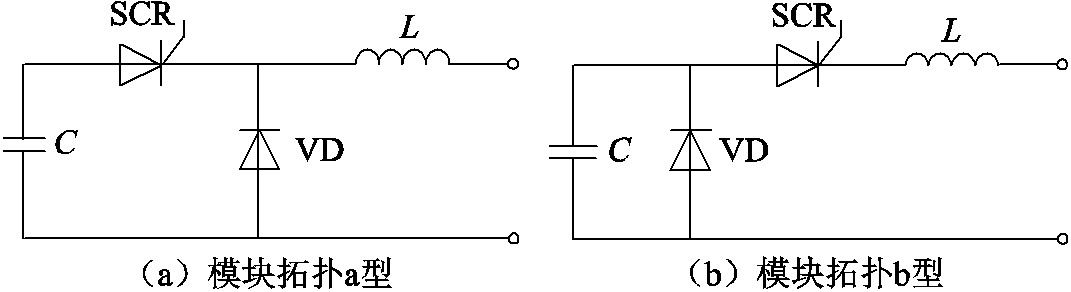
除涉及元件自身的体积和质量外,脉冲功率电源的储能密度也与电路拓扑结构密切相关。目前所采用的模块拓扑主要分为两种,如图1所示。两种拓扑均包含4个主要元器件:脉冲电容器C、晶闸管SCR、续流二极管VD和脉冲电抗器L,结构形式简单,普遍应用于特种直线电机系统。
图1 两种电容储能型脉冲功率电源的模块拓扑
Fig.1 Two module topologies of the capacitive pulsed power supply
负载特性是电源设计的前提。根据不同的负载特性,开展针对性的电源设计,可以达到系统的小型化、轻量化目的。
图1所示电源模块的拓扑结构主要应用于简单型特种直线电机,其脉冲电抗器L的主要作用是中间储能、调节脉宽和保障元件安全。相比简单型负载,增强型负载由于具备更高的初始电感值,在所有模块同步触发的条件下,初始电感L0可用来代替单模块中的脉冲电抗器L,不影响系统的整体功能和安全性。
本文针对增强型负载,对同步触发下无电抗器电容储能型脉冲功率电源(以下简称无电抗器电源)开展研究。相比现有电源,无电抗器电源通过去除脉冲电抗器,减小了电源系统的体积和质量,具备提升脉冲功率电源小型化、轻量化工程需求的能力。
众多电源模块同步触发及同时开通是一个难以实现的工程难题。如何实现工程上的同时开通,即开关抖动量关系到该种电源在感性负载条件下能否成功应用的关键。本文所要解决的问题是:当考虑实际运行时,各模块晶闸管的导通会存在μs级或亚μs级的延时,即晶闸管存在导通时延抖动。基于电源实际运行情况,通过理论分析电源与负载的匹配特性,确定电源拓扑,并提出该型电源的重点关注问题,开展初步验证。
对于无电抗器电源的理论分析,考虑各元件内阻的总拓扑如图2所示。其中,C为脉冲电容器电容,RC为脉冲电容器的等效内阻,U0为脉冲电容器的预充电压;Si(i=1, 2, , N)为晶闸管,RSCR为晶闸管的等效内阻;VDi(i=1,2,, N)为续流二极管,RD为二极管的等效内阻;Lcable、Rcable分别为电源模块与汇流排连接小电缆的电感和电阻;Lload、Rload分别为负载的等效电感和等效电阻。
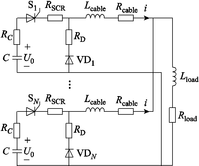
图2 无电抗器电源总拓扑
Fig.2 The topology of the non-inductor capacitive pulsed power supply
鉴于电容储能型脉冲功率电源的理论分析已基本完善[15-16],针对实际运行时存在抖动的无电抗器电源,仅分析同步放电的初期阶段。
在系统抖动范围内对时间进行分区,按照晶闸管导通时刻的先后顺序,可依次分为T0模块、T1模块、、Tk模块,对应晶闸管的导通时刻分别为Td0时刻、Td1时刻、、Tdk时刻。
由于系统导通时延抖动一般为μs级,因此设立假设前提1:负载在同步放电初期为静态负载。这意味着电枢在装填位置保持静止,即
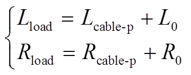 (1)
(1)
式中,Lcable-p、Rcable-p分别为汇流排与轨道之间并联大电缆的电感和电阻;L0、R0分别为轨道的初始电感和初始电阻。
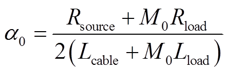
若共有M0个T0模块,针对每个电源模块的等效拓扑如图3所示。令Rsource RC
RC RSCRRcable、Td00,得到模块内晶闸管电流i0为
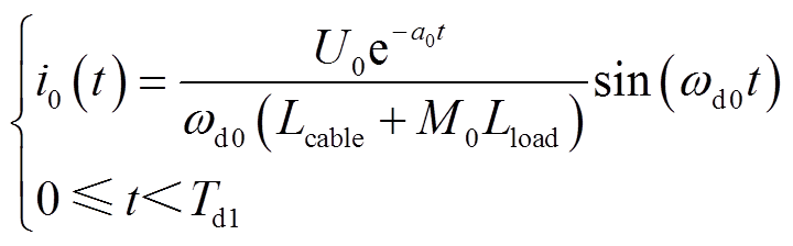 (2)
(2)
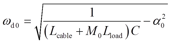
其中
 (3)
(3)
 (4)
(4)
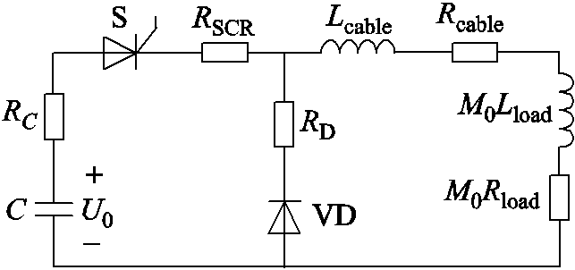
图3 T0模块的等效拓扑
Fig.3 The equivalent topology of the T0 module
由式(2)可知,增强型负载等效至电源侧被放大M0倍,这意味着同步触发是无电抗器电源与感性负载匹配的前提。
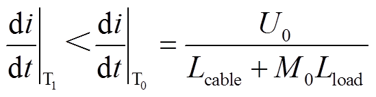
求解T0模块晶闸管导通时刻(Td0时刻)的电流上升率为
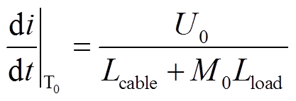 (5)
(5)
若共有M1个T1模块,Td1时刻针对负载等效的s域拓扑如图4所示。
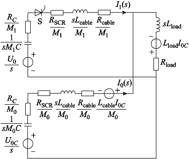
图4 Td1时刻T1模块的等效拓扑
Fig.4 The equivalent topology of the T1 module at Td1
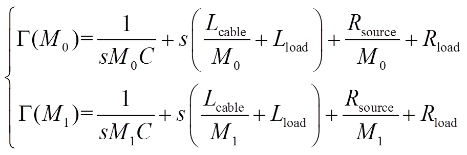
得到T0模块、T1模块针对负载等效的s域表达式 、
、 分别为
分别为
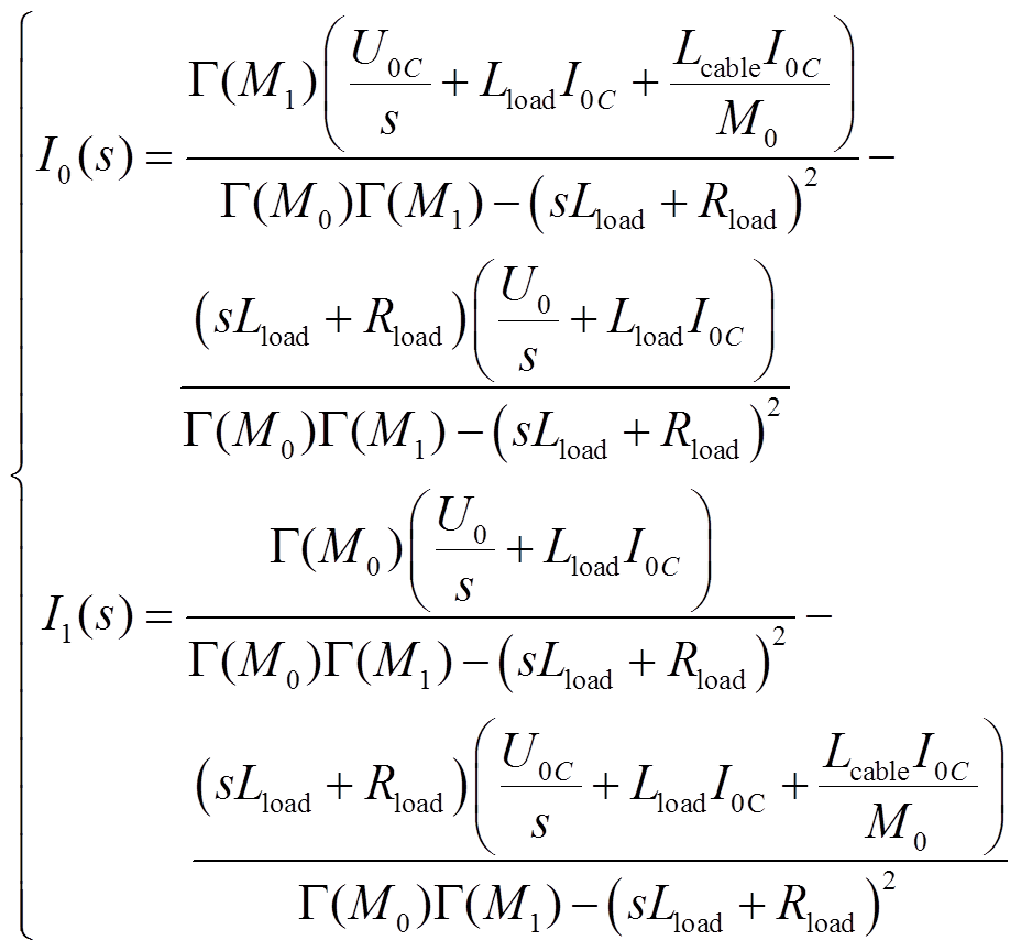 (6)
(6)
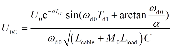
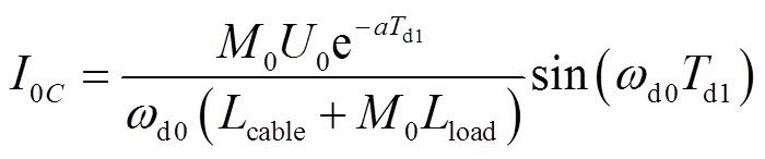
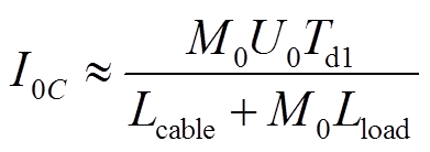
式中,U0C、I0C分别为T0模块在Td1时刻电容的初始电压和回路内电感的初始电流。
 (7)
(7)
 (8)
(8)
 (9)
(9)
为简化计算,设立以下假设前提。
假设前提2:Td1时刻电容的初始电压U0C近似为电容的预充电压U0,即
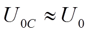 (10)
(10)
假设前提3:Td1时刻电感的初始电流I0C近似为其一阶泰勒展开,即
 (11)
(11)
基于以上三个假设前提,求解T1模块晶闸管导通时刻的电流上升率,为
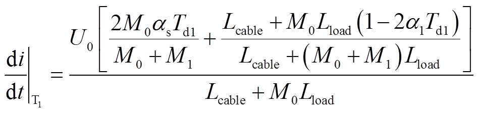 (12)
(12)
其中
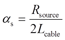 (13)
(13)
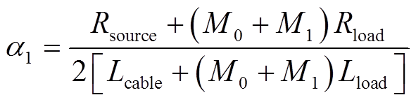 (14)
(14)
根据实际应用场合,即电容mF级,电感μH级,电阻mΩ级,延迟时间μs级,可知
 (15)
(15)
若Tk模块共Mk个。对于在Tdk时刻前晶闸管导通的模块,由于各模块元件参数相同,可视作模块数为 、导通时刻等效为Td_eq的Teq模块。同样基于三个假设前提:
(1)负载在同步放电初期为静态负载。
(2)Tdk时刻电容的初始电压近似为电容的预充电压,即
 (16)
(16)
(3)Tdk时刻电感的初始电流近似为一阶泰勒展开,即
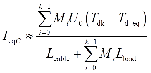 (17)
(17)
同理可求解Tdk时刻Tk模块晶闸管导通时刻的电流上升率。
 (18)
(18)
其中
 (19)
(19)
由式(19)可知,当无电抗器电源的晶闸管存在导通时延抖动时,最先触发模块(T0模块)内晶闸管的电流上升率是系统内最大电流上升率。
选取实验室晶闸管导通时延抖动相对接近的13个模块组成无电抗器电源。在1kV的电容预充电压下,对膛口短路的增强型负载进行同步放电试验。在相同负载和预充电压下,与保留电抗器的传统电源进行同步放电试验对比。
试验采用的晶闸管所能承受的浪涌电流峰值为24kA,电流上升率限值为250A/μs。根据测量与计算,系统元件的主要参数见表1。
表1 同步放电试验系统的主要参数
Tab.1 Main parameters of the synchronous dischargepulsed power supply
参数数值 脉冲电抗器电感均值/μH13.28 各模块与汇流排连接小电缆电感均值/μH0.24 负载与汇流排连接大电缆电感Lcable_p2/μH0.45 轨道电感梯度1.08 轨道初始电感L0/μH1.5 轨道长度l/m2.5
传统电源与无电抗器电源各模块的电流波形分别如图5a、图5b所示。对于传统电源,脉冲电抗器的容差会导致各模块输出的电流峰值不同;对于无电抗器电源,由于回路内电感值减小,且各模块与汇流排之间的小电缆长度不一致,导致电流波形存在差异。其中,无电抗器电源电流下降沿的差异较大,部分模块在电流下降沿阶段非平滑下降,而是存在一个转折点,该转折点的出现主要是由电流换路至续流二极管支路导致的。
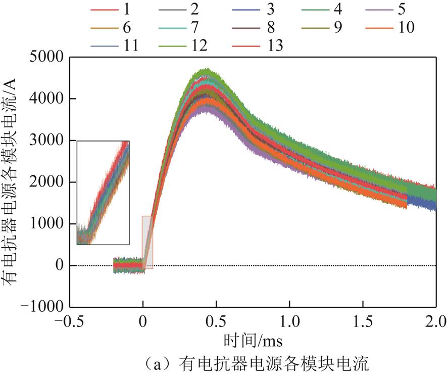
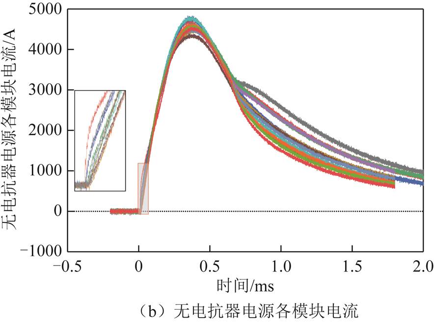
图5 同步触发下各电源模块电流波形
Fig.5 Current waveforms of each pulsed power module with the synchronous trigger method
根据图5,在保留电抗器和去除电抗器的条件下,得到各模块电流峰值的平均值分别为4.32kA、4.62kA。二者数值接近,且远小于晶闸管所能承受的浪涌电流峰值,这意味着系统内晶闸管不会出现因电流峰值过大而损坏的情况。试验结果与理论分析保持一致,即同步触发是无电抗器电源与感性负载匹配的前提。
对于无电抗器电源,模块1作为晶闸管最快导通的模块,其导通时刻的电流上升率为系统内最大电流上升率,与理论分析结论相符。
根据试验结果,模块1、2作为最快放电的两个模块,二者之间的时延差大于0.5μs。在该情况下,T0模块的模块数M01。根据表1,在保留电抗器和去除电抗器的条件下,计算模块1晶闸管的电流上升率分别为55.04A/μs、204.50A/μs。在去除电抗器后,晶闸管的电流上升率增大至3.72倍。将计算的电流上升率与试验波形进行对比,如图6所示。
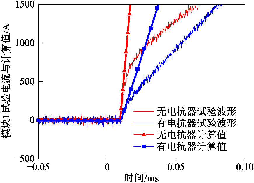
图6 模块1试验电流与计算值
Fig.6 Current waveforms of tests and calculation in the module No.1
由图6可知,计算结果与试验结果基本一致。这意味着,去除电抗器后,若晶闸管的电流上升率超过限值,过大的电流密度会使得导通区域局部温度过高,可能导致晶闸管性能的退化甚至烧毁。为了保证无电抗器电源的安全运行,需要重点考虑最先触发模块晶闸管的电流上升率。
有电抗器、无电抗器电源模块内部结构如图7所示。两种电源模块内所采用的脉冲电容器标称值2mF、最大预充电压3kV、储能密度0.56MJ/m3。在最大预充电压下,电源模块总储能9kJ。
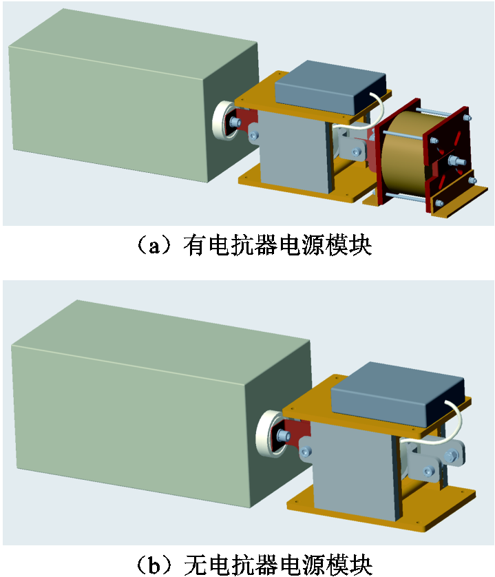
图7 两种电源模块内部结构
Fig.7 Inner structure of two pulsed power modules
通过测量与计算,两种电源模块的小型化、轻量化水平见表2。去除电抗器后,电源模块体积储能密度为0.32MJ/m3,提升了23.1%;质量储能密度为0.26kJ/kg,提升了13.0%。
表2 两种电源模块的对比
Tab.2 Comparison of two pulsed power modules
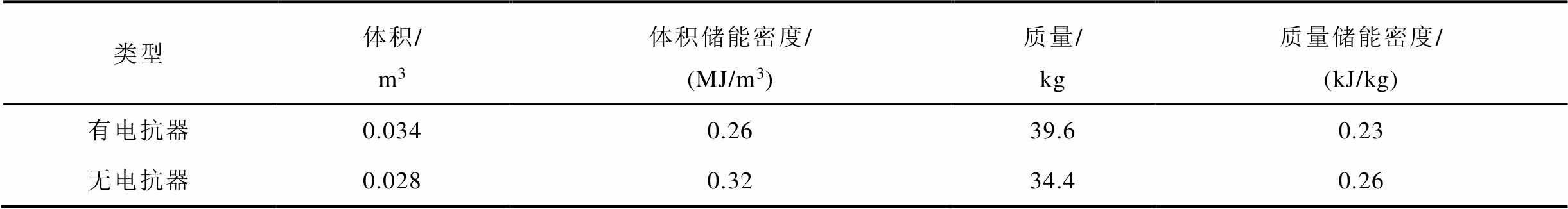
类型体积/m3体积储能密度/(MJ/m3)质量/kg质量储能密度/(kJ/kg) 有电抗器0.0340.2639.60.23 无电抗器0.0280.3234.40.26
本文针对感性负载条件下的无电抗器电源开展研究,基于理论分析与试验验证,所得结论如下:
1)同步触发是无电抗器电源与感性负载匹配的前提。当N个模块进行同步放电时,感性负载等效至电源侧被放大N倍,可以替代单模块电源中脉冲电抗器的功能。
2)当考虑晶闸管导通时延抖动时,最先触发模块的电流上升率是系统内最大电流上升率,工作环境最恶劣,在电源设计时需要予以考虑。
3)去除电抗器后,电源模块的体积储能密度提升了23.1%;质量储能密度提升了13.0%。
4)根据推导公式,为保障系统的安全运行,负载初始电感越高,系统运行越可靠。
参考文献
[1] 李贞晓, 郝双鹏, 马富强, 等. 电炮用脉冲电源模块技术现状与发展[J]. 兵工学报, 2020, 41(增刊1): 1-7.
Li Zhenxiao, Hao Shuangpeng, Ma Fuqiang, et al. Current situation and development of pulsed power supply module technology for electric gun[J]. Acta Armamentarii, 2020, 41(S1): 1-7.
[2] McNab I R. Pulsed power options for large EM launchers[J]. IEEE Transactions on Plasma Science, 2015, 43(5): 1352-1357.
[3] McNab I R. Large-scale pulsed power opportunities and challenges[J]. IEEE Transactions on Plasma Science, 2014, 42(5): 1118-1127.
[4] 李军, 严萍, 袁伟群. 电磁轨道炮发射技术的发展与现状[J]. 高电压技术, 2014, 40(4): 1052-1064.
Li Jun, Yan Ping, Yuan Weiqun. Electromagnetic gun technology and its development[J]. High Voltage Engineering, 2014, 40(4): 1052-1064.
[5] 朱博峰, 鲁军勇, 张晓, 等. 高压大容量金属化膜脉冲电容器提高储能密度的工艺改进与试验研究[J]. 海军工程大学学报, 2020, 32(1): 20-25.
Zhu Bofeng, Lu Junyong, Zhang Xiao, et al. Crafts improvement and experimental research for increasing energy storage density of high-voltage-capacity metalized film pulse capacitor system[J]. Journal of Naval University of Engineering, 2020, 32(1): 20-25.
[6] Jow T R, MacDougall F W, Ennis J B, et al. Pulsed power capacitor development and outlook[C]//2015 IEEE Pulsed Power Conference (PPC), Austin, TX, 2015: 1-7.
[7] 李化, 李智威, 黄想, 等. 金属化膜电容器研究进展[J]. 电力电容器与无功补偿, 2015, 36(2): 1-4, 18.
Li Hua, Li Zhiwei, Huang Xiang, et al. Research progress on metallized film capacitors[J]. Power Capacitor & Reactive Power Compensation, 2015, 36(2): 1-4, 18.
[8] 李化, 王文娟, 李智威, 等. 2.7MJ/m3高储能密度脉冲电容器的研制[J]. 高压电器, 2016, 52(3): 69-73, 80.
Li Hua, Wang Wenjuan, Li Zhiwei, et al. Development of high energy density (2.7MJ/m3) pulse capacitor[J]. High Voltage Apparatus, 2016, 52(3): 69-73, 80.
[9] Macdougall F, Ennis J, Yang Xiaohui, et al. High energy density capacitors for pulsed power applications[C]//2009 IEEE Pulsed Power Conference, Washington, 2009: 774-778.
[10] MacDonald J R, Schneider M A, Ennis J B, et al. High energy density capacitors[C]//2009 IEEE Electrical Insulation Conference, Montreal, 2009: 306-309.
[11] 李化, 方田, 张晨晨. 电容器级新型储能电介质的储电性能研究[J]. 电力电容器与无功补偿, 2021, 42(2): 54-58.
Li Hua, Fang Tian, Zhang Chenchen. Study on electrical storage performance of capacitor level new energy storage dielectrics[J]. Power Capacitor & Reactive Power Compensation, 2021, 42(2): 54-58.
[12] 叶润峰, 裴家耀, 郑明胜, 等. 高介电聚丙烯基纳米复合薄膜介电及储能性能抗老化特性[J]. 电工技术学报, 2020, 35(16): 3529-3538.
Ye Runfeng, Pei Jiayao, Zheng Mingsheng, et al. Anti-aging characteristics of dielectric and energy storage of high dielectric polypropylene based nanocomposite films[J]. Transactions of China Electrotechnical Society, 2020, 35(16): 3529-3538.
[13] Liu Biao, Yang Minhao, Zhou Wenying, et al. High energy density and discharge efficiency polypropylene nanocomposites for potential high-power capacitor[J]. Energy Storage Materials, 2020, 27: 443-452.
[14] 沈忠慧, 江彦达, 李宝文, 等. 高储能密度铁电聚合物纳米复合材料研究进展[J]. 物理学报, 2020, 69(21): 105-117.
Shen Zhonghui, Jiang Yanda, Li Baowen, et al. Research progress of ferroelectric polymer nanocomposites with high energy storage density[J]. Acta Physica Sinica, 2020, 69(21): 105-117.
[15] 徐麟, 张军, 刘佳, 等. 脉冲功率源瞬态反向过电流机理及优化[J]. 电工技术学报, 2020, 35(S2): 629-635.
Xu Lin, Zhang Jun, Liu Jia, et al. Mechanism and optimization of transient reverse overcurrent in pulse power system[J]. Transactions of China Electrotechnical Society, 2020, 35(S2): 629-635.
[16] 彭之然, 刘华, 汪光森, 等. 基于多模块分时放电半解析模型的脉冲电源触发策略[J]. 电工技术学报, 2021, 36(增刊1): 54-61.
Peng Zhiran, Liu Hua, Wang Guangsen, et al. Trigger strategy of pulsed power supply based on the semi-analytical model of sequentially-triggered power units[J]. Transactions of China Electrotechnical Society, 2021, 36(S1): 54-61.
Abstract The capacitive pulse power supply (CPPS) is the first choice of pulse power systems for special linear motors. As researches progress ever further, higher requirements for the energy density, volume and mass of the CPPS need to be addressed properly in order to be suitable to the engineering application. Researches on the miniaturization and lightweight of the CPPS have focused on the high energy density capacitors, which is rather difficult to achieve a substantial improvement in the near future. The topology of the CPPS, determined by characteristics of pulse power loads, is also strongly linked to the energy density. In this paper, the non-inductor capacitive pulse power supply (NICPPS) is proposed. The NICPPS is the topological optimization on the basis of the traditional CPPS, and provides an achievable approach to realize miniaturization and lightweight in the synchronous triggering mode. However, in the real engineering environment, the pulse forming units (PFUs) cannot discharge synchronously in an ideal way. The impact of the jitter caused by thyristers’ turn-on delay in the NICPPS must be considered. The range of the jitter is at microsecond or sub-microsecond levels, which is rather shorter compared to the electromagnetic launching process at millisecond levels. Three assumptions based on the jitter of microsecond or sub-microsecond levels are proposed. (1) The parameters of the load are constant rather than varying with the displacement of the armature. (2) The initial voltage of capacitors is equal to the charging voltage. (3) The initial current of inductors is equal to its first order Taylor expansion. Based on three assumptions, the circuit including the NICPPS and the load is analyzed. In the circuit analyses, the PFUs are divided into several modules according to the conduction time of thyristors. The Tk (k=0,1,2, ) module contains the PFUs where the conduction of thyrister is at Tdk, and its corresponding number of PFUs is Mk. The T0 module, which includes first triggered thyristors, has the maximum current rise rate among the whole system. The current rise rate of the T0 module is proportional to U0 and inversely proportional tothe sum of Lcable and M0·times of Lload, where U0 is the charging voltage of the capacitor, Lcable and Lload are the inductance of the cable and the static load respectively. The theoretical analyses show that the current rise rate of the thyristers in the T0 module is an important factor as regards the reliability of the NICPPS. Based on the derived formula, the larger the initial inductance of the load and the number of the PFUs in the T0 module are, the more reliable the NICPPS is. The circuit analyses also show that N numbers of PFUs discharge synchronously, the inductive load is equivalent to N times amplified on the side of the PFU. The initial inductance of an augmented railgun is much higher than in the case of a simple railgun. In the synchronous triggering mode, the much higher initial inductance of the augmented railgun performs the function of the pulse forming inductors in the traditional CPPS, which offers feasibility to remove pulse forming inductors. Compared to the traditional CPPS, the energy densities of the PFU in the NICPPS in terms of volume and mass are increased by 23.1% and 13.0% respectively. The experiment was carried out to verify the conclusions of the circuit analyses. The experimental results show that the average current peaks of the thyristors in the traditional CPPS and NICPPS are 4.32kA and 4.62kA respectively, which means the initial inductance of the augmented railgun restrains the current peaks of the thyristors from increasing sharply on the condition of synchronous discharge. The current rise rates of first triggered thyristors in the traditional CPPS and NICPPS are 55.04A/μs and 204.50A/μs respectively at the initial stage of discharge. It is demonstrated that the theoretical results quantitatively consistent with the experimental ones. In conclusion, the NICPPS can improve the energy density, and show the potential of reducing the system’s volume and weight. The synchronous triggering mode can ensure the safety and reliability of operations, and the jitter of thyristors needs to be taken serious consideration into. The impact of jitter is analyzed by theory and verified by experiments, which can be used as a frame of reference for the further development of the prototype.
keywords:Capacitive pulsed power supply, miniaturization, lightweight, turn-on delay jitter, non-inductor
DOI:10.19595/j.cnki.1000-6753.tces.211788
中图分类号:TM833
收稿日期 2021-11-04
改稿日期 2021-12-06
叶文怡 女,1992年生,助理工程师,研究方向为大电流脉冲放电技术及应用。E-mail:yewenyi@mail.iee.ac.cn
严 萍 女,1965年生,研究员,博士生导师,研究方向为高电压绝缘技术、脉冲功率技术和电磁发射技术等。E-mail:pingyan@mail.iee.ac.cn(通信作者)
(编辑 赫 蕾)