基于激活函数的LCC-S型无线电能传输系统建模和稳定性分析
胡秀芳 王 跃 吕双庆 赵德林 马天录
(电力设备电气绝缘国家重点实验室(西安交通大学) 西安 710049)
摘要 基于电力电子器件的无线电能传输(WPT)系统是一种开关系统,其大信号模型是研究系统运行特性和稳定性的基础。建模的关键是如何描述系统中的非线性、离散开关变量,为解决这一问题,该文提出一种基于S型激活函数的建模方法。S型激活函数是连续、平滑、可微的且在一定值时具有饱和特性,因此可利用陡度因子较大的激活函数来近似开关的切换过程,将WPT系统由离散的开关系统转变为连续系统。该文以LCC-S型WPT系统为研究对象,构建其开环和闭环模式下激活函数模型,利用该模型分析控制器参数和系统参数对瞬态行为和稳定性的影响,并通过仿真和实验进行验证。结果表明,所构建的模型与仿真和实验结果吻合较好。该模型数学表达式结构简单统一,物理意义明确,是一个具有普遍意义的高精度大信号连续模型。
关键词:无线电能传输系统 LCC-S补偿 激活函数 大信号模型 稳定性
0 引言
无线电能传输[1-3](Wireless Power Transfer, WPT)系统根据电路运行特性,可以将一个开关周期分为不同的开关状态,在每个开关状态下,对应一个由连续状态变量表示的子系统,因此WPT系统可以被视为由离散开关状态和连续状态变量组成的开关系统,开关器件在每个连续子系统中有选择地保持某一固定开关状态,以满足系统动态响应的要求。建模的关键是描述离散开关变量和连续状态变量之间的相互作用并建立统一的模型[4]。状态空间平均法[5]使用状态变量在一个开关周期的平均值建立模型,只保留状态变量的低频成分,忽略其高频纹波分量,从而建立一个连续的系统模型。然而,由于在稳态运行时LCC-S型WPT系统[6-7]中各电量是交流量,对其进行状态空间平均将丢失其最主要的波形信息,因此不能使用状态空间平均法进行建模。
为此,研究学者提出了广义状态空间平均(Generalized State-Space Averaging, GSSA)法[8-9]、扩展描述函数(Extended Describing Function, EDF)法[10]、耦合模理论[11]及离散迭代模型[12]等方法来解决WPT系统的建模问题。广义状态空间法和描述函数法都实现了从非线性时变不连续的状态空间方程到线性时不变连续状态空间方程,甚至局部线性化方程的转换。相比较而言,广义状态空间法从原始状态空间方程开始,便不再需要物理模型,仅由数学分析便完成建模。扩展描述函数法通过电路的基波分析给出描述函数的具体形式,物理概念相对明确。两种方法的共同点是都用两个或多个缓慢变化的量去描述一个快速变化且波形接近正弦的量(广义状态空间平均法使用共轭的第1项和第-1项傅里叶系数,扩展描述函数法使用正弦和余弦分量的系数),因此,它们虽然克服了系统的非线性、时变性和不连续性,但代价是增加了系统的阶数[12]。此外,当WPT系统工作在断续模式(流入整流桥的电流断续)时,系统谐波成分较大,上述两种方法中采用的简化处理均会带来较大误差。耦合模理论将WPT系统的原、副边描述为两个复变量,可以很好地解释能量的交换情况。但是,耦合模理论只能描述具有低耦合系数的系统。该方法的另一个局限是从能量的角度描述WPT系统中的高阶补偿网络较为困难。
由于开关器件的存在,等效电路拓扑随着系统开关器件的开关状态变化而变化。离散迭代模型根据开关器件的状态,将一个开关周期分为不同的开关状态,得到每个开关状态下的数学映射,将上一个开关状态初始时刻的状态变量通过该数学映射得到下一个开关状态初始时刻的状态变量。如此反复进行迭代运算就得到了系统的离散迭代模型[12]。离散迭代模型由于保留了低频次与开关频次所有的信息,因此具有较高的精确度。但是当系统工作于断续模式时,开关状态复杂,求解难度高[13]。
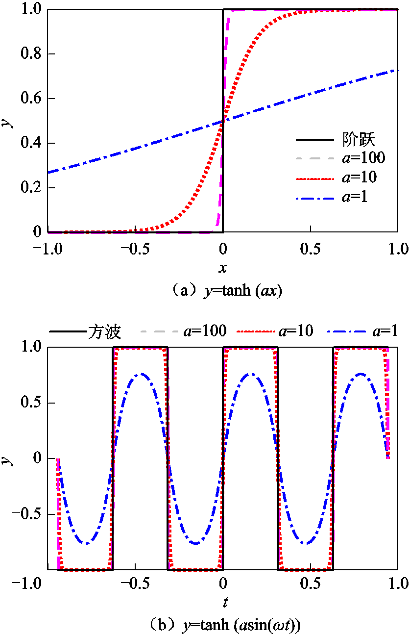
WPT系统建模的关键是如何寻求一个统一的模型来表示所有开关状态下的等效电路模型。WPT系统通常采用脉冲宽度调制(Pulse Width Modulation, PWM)来保证谐振过程的完成。本文通过引入激活函数[14]为WPT系统建立统一的连续系统模型,使连续系统理论可以直接应用于分析WPT系统。S型激活函数是神经网络中重要的激活函数之一[15],其具有连续性、平滑性、可微性、有界且严格单调性,已被用于描述滑模控制器中的系统模式转换[16],描述电路的模态变换[17]等。
基于激活函数可建立WPT系统在开环和闭环模式下的模型,然而,在闭环控制模式下,数字控制系统中的时间延迟往往被忽略。延时环节使WPT系统更加复杂。对于没有时滞的系统,可以在输入和输出之间建立一定的映射关系[18]。但延时的存在可能会扰乱这种特定的关系[19]。对于相同的采样信号,数字控制系统中的时间延迟可能会导致WPT系统出现不稳定现象。 WPT系统性能将不可避免地受到影响甚至恶化。因此,考虑延时环节影响的稳定性分析是必要的。
为了避免这些问题,对稳定性分析中的时间延迟进行近似成为一个优选的解决方案。时间延迟可以通过一阶滞后[20]、泰勒展开[21]、Pade近似[22-23]等来近似。与一阶滞后和泰勒级数相比,Pade近似凭借其有理多项式的形式而具有更好的性能。此外,Pade近似能够处理相对较短的延迟[24]。由于数字控制系统的时间延迟在微秒量级,Pade近似可能更合适。因此,本文采用Pade近似等值延时环节来分析系统的稳定性。
由于LCC-S型WPT系统具有发射电流恒定、对线圈未对准的高度容忍性、轻载或副边开路时的高度稳定性等优点而被广泛应用。因此,本文引入S型激活函数,针对移相控制下的LCC-S型WPT系统进行建模和稳定性分析。首先,介绍了S型激活函数的特性;其次,推导出基于激活函数的LCC-S型WPT系统在开环模式下的模型;然后,基于五阶Pade等值近似延时环节,建立了闭环模式下的模型,揭示系统中存在的不稳定现象;最后,通过仿真和实验验证该模型的有效性。此建模过程对任何其他补偿网络均有效。
1 激活函数
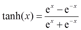
常用的S型激活函数有log-sigmoid和tan-sigmoid,这两个函数的曲线是“S”型,其中tan-sigmoid函数表达式为
2 LCC-S型WPT系统稳态运行特性
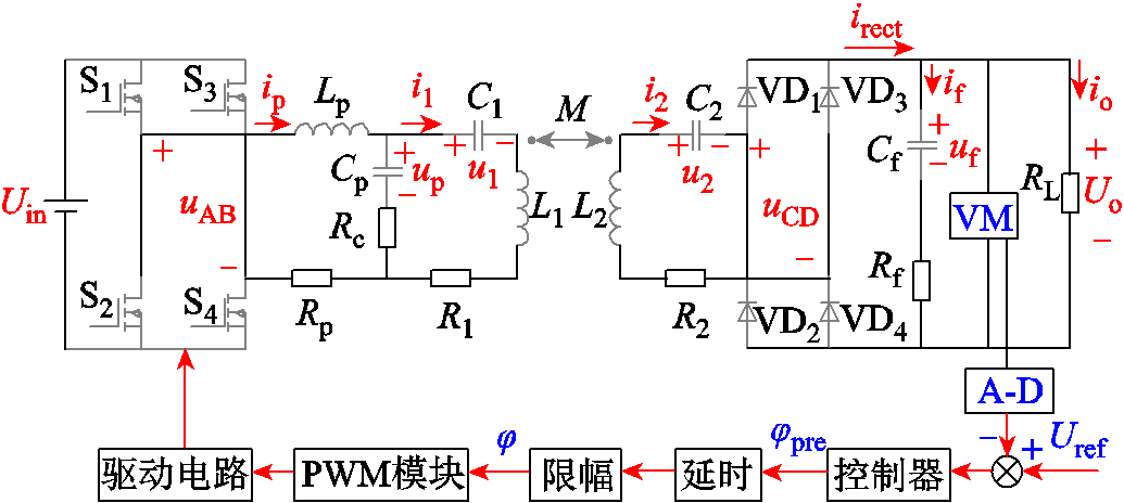
LCC-S型WPT系统电路拓扑如图2所示,由全桥逆变器、谐振网络和全桥整流器组成。全桥逆变器将直流电压Uin逆变为高频交流电压uAB,从而激励由Lp、Cp、C1组成的LCC补偿网络和发射线圈L1,再由发射线圈L1以交变电磁场的形式将能量传输至接收侧,接收侧由L2、C2串联网络拾取能量,高频交流电压uCD经高频整流桥和滤波电容Cf,传递给负载电阻RL,完成从直流电压Uin到直流电压Uo的无线能量传输。其中,Rp为Lp的等效串联电阻与MOSFET的导通电阻之和,R1为L1和C1等效串联电阻之和,R2为L2、C2的等效串联电阻及整流二极管的导通电阻之和,Rc为Cp的等效串联电阻,Rf为Cf的等效串联电阻,j为移相角,系统的工作周期为Ts。
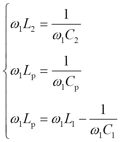
对于LCC-S型WPT系统,运行的谐振条件为
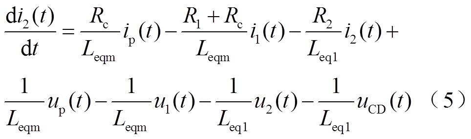
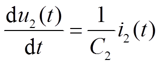
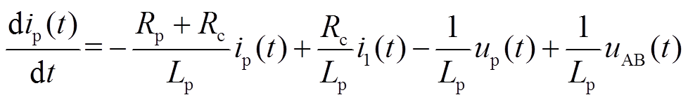
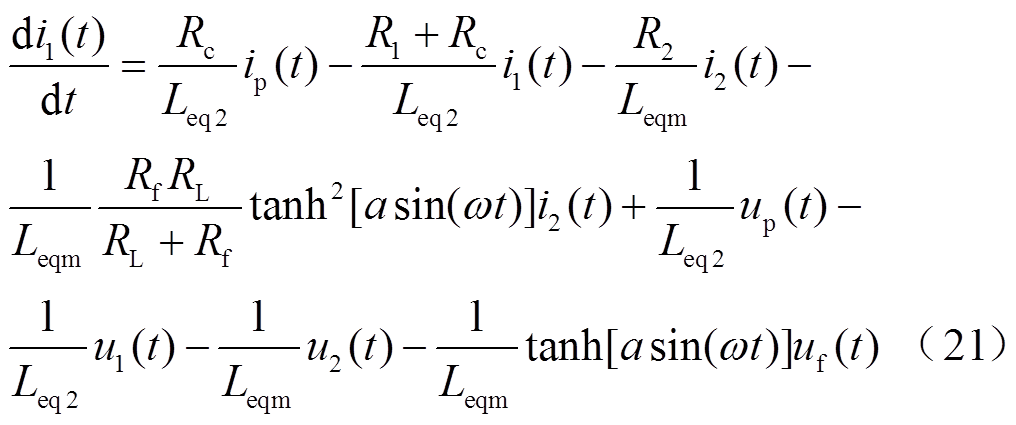
根据图2,建立系统微分方程为
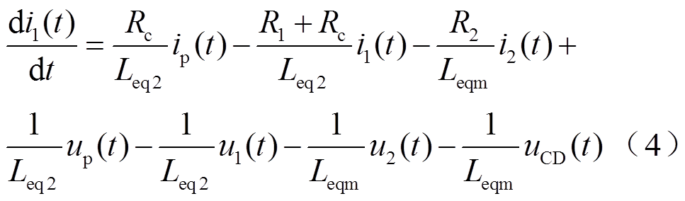
 (7)
(7)
 (8)
(8)
输出方程为
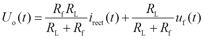 (10)
(10)
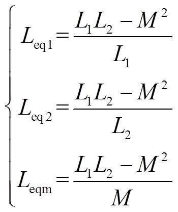
其中
系统中包含三个非线性项,分别是逆变器输出电压uAB、整流桥输入电压uCD和整流桥输出直流电流irect,将其定义为
 (12)
(12)
 (14)
(14)
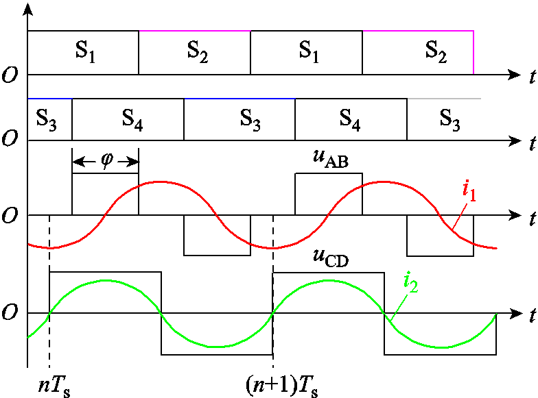
式中,当nTs+0.25Ts(1-j/p)t≤nTs+0.25Ts(1+ j/ p)时,SAB(t)=1;当(n+0.5)Ts+0.25Ts(1-j/ p)t≤(n+1)Ts-0.25Ts(1-j/ p)时,SAB(t)=-1;其余为0。当nTst≤(n+0.5)Ts时,SCD(t)=1,当(n+0.5)Tst≤(n+1)Ts时,SCD(t)=-1。
取状态变量x(t)、输入变量u(t)和输出变量y(t)分别为
 (16)
(16)
 (17)
(17)
式(3)~式(10)所描述的系统是一个非线性时变不连续系统,不便于进行分析。使用本文提出的激活函数可以将其转变为连续系统。
3 基于激活函数的LCC-S型WPT系统模型
3.1 开环系统建模
逆变器输出电压波形如图3所示。对于式(12)中SAB,利用周期性激活函数可表示为
式中,w为WPT系统工作角频率; 为移相角。
为移相角。
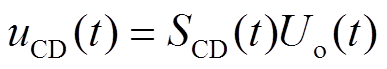
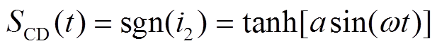
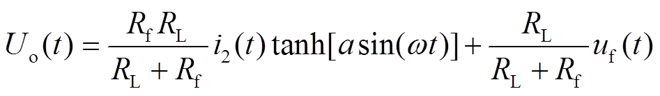
根据图3所示的整流桥输入电压、输入电流及输出电流波形,整流桥输入电压uCD取决于整流桥输入电流i2的方向。若i2为正,则uCD=Uo;若i2为负,则uCD=-Uo,即uCD = sgn(i2)Uo。整流桥输出电流是整流桥输入电流的绝对值,可表示为|i2|= i2sgn(i2)。对于式(13)中SCD,利用周期激活函数可表示为
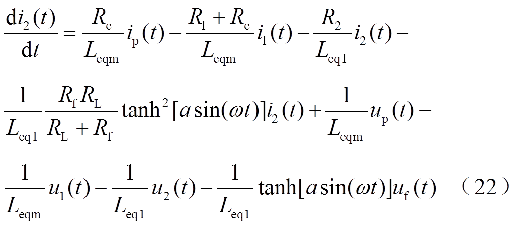
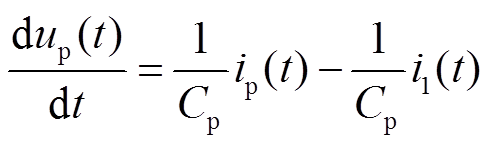
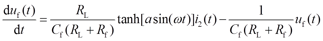
因此,LCC-S型WPT系统可以表示为一个统一的连续时间系统模型,即
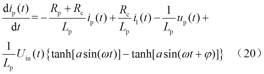
 (23)
(23)
(25)
 (26)
(26)
输出方程为
3.2 闭环系统建模
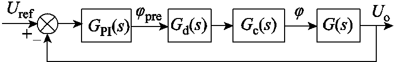
本文中,数字控制闭环系统框图如图4所示。
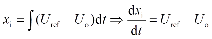
对于积分环节,将引入额外的状态变量xi,即
图4中,GPI(s)为PI控制器的传递函数;kp与ki分别为PI控制器的比例与积分系数,则PI控制器的输出信号φpre可表示为
 (29)
(29)
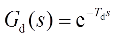
在WPT系统中,不可避免地会引入延时环节,主要包括硬件延时和数字控制器引入的采样延时、计算延时及 PWM延时等。在本文中,硬件延时主要包括电压检测电路的延时,MOSFET驱动电路的延时以及MOSFET开通与关断的延时,延时时间用Td表示,实际测量Td=87μs。
数字控制器由于采用离散实现方式,工程上通常选择1.5Ts作为延时,Ts为采样周期,即采用 对延时环节进行表征。
 (31)
(31)
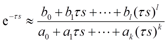
在本文中,采用Pade近似[25]以将延时环节表示为有限维多项式,即
式中,τ = Td+1.5Ts; ;
; 。
。
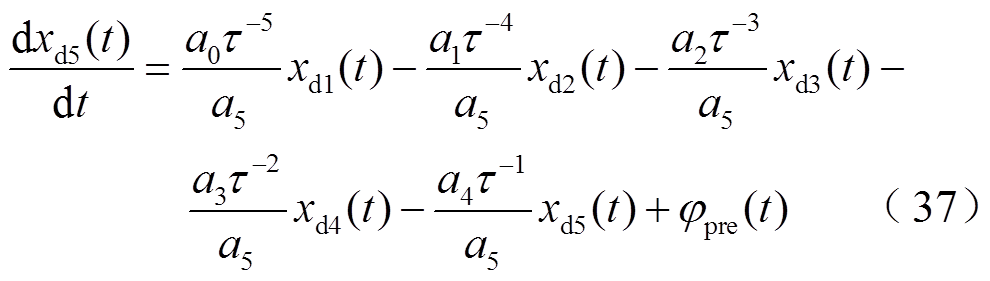
利用传递函数实现问题的一般性方法,可将式(32)转换为式(33)~式(37)所示的等价微分方程,其中Pade近似的阶数为5。
 (34)
(34)
 (35)
(35)
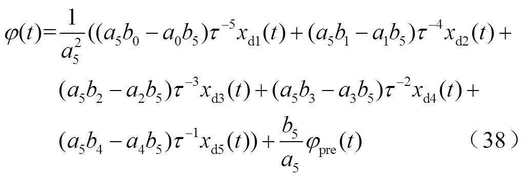
控制系统的输出为
结合式(20)~式(38)即可得到描述整个LCC-S型WPT系统在闭环控制模式下的统一连续时间系统模型,此处不再具体给出。
4 仿真与实验验证
为了验证所建立的激活函数模型的准确性,搭建系统仿真和实验平台,参数见表1,本文仿真和实验均采用此参数。
表1 LCC-S型WPT系统电路参数
Tab.1 The parameters of LCC-S compensation WPT system
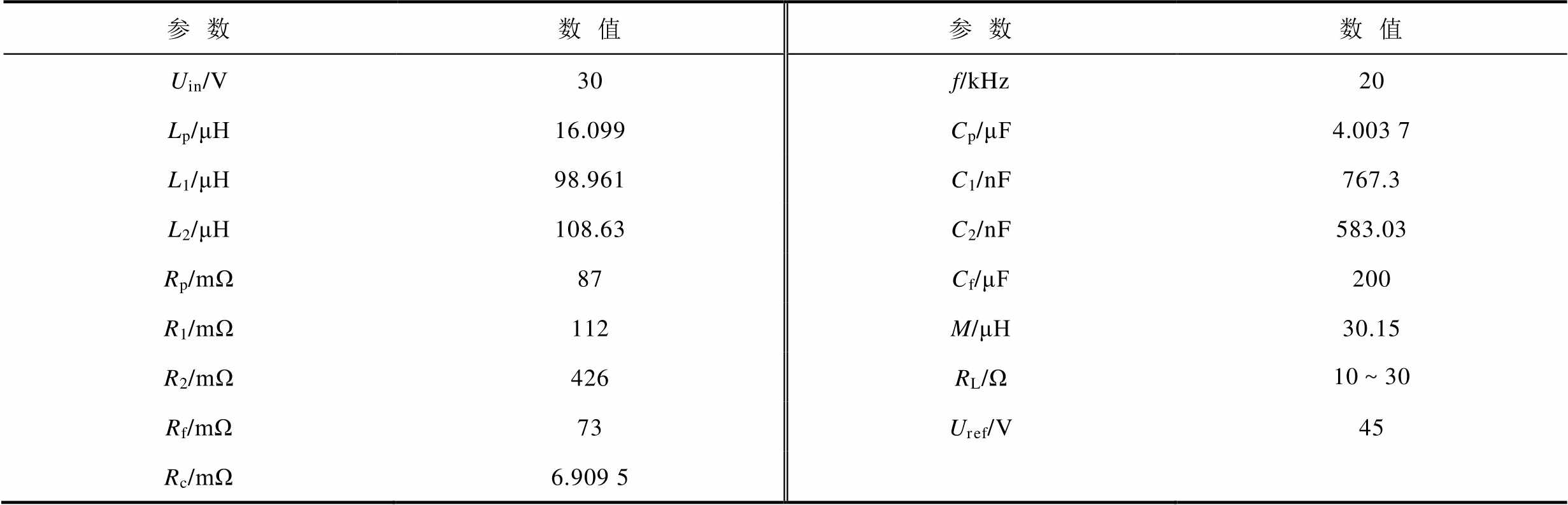
参数数值参数数值 Uin/V30f/kHz20 Lp/μH16.099Cp/μF4.003 7 L1/μH98.961C1/nF767.3 L2/μH108.63C2/nF583.03 Rp/mΩ87Cf/μF200 R1/mΩ112M/μH30.15 R2/mΩ426RL/Ω10~30 Rf/mΩ73Uref/V45 Rc/mΩ6.909 5
在实验室中搭建系统实验样机,如图5所示。实验样机包括直流电源、全桥逆变器、LCC-S谐振网络、全桥整流器和电子负载。
4.1 稳态模型验证
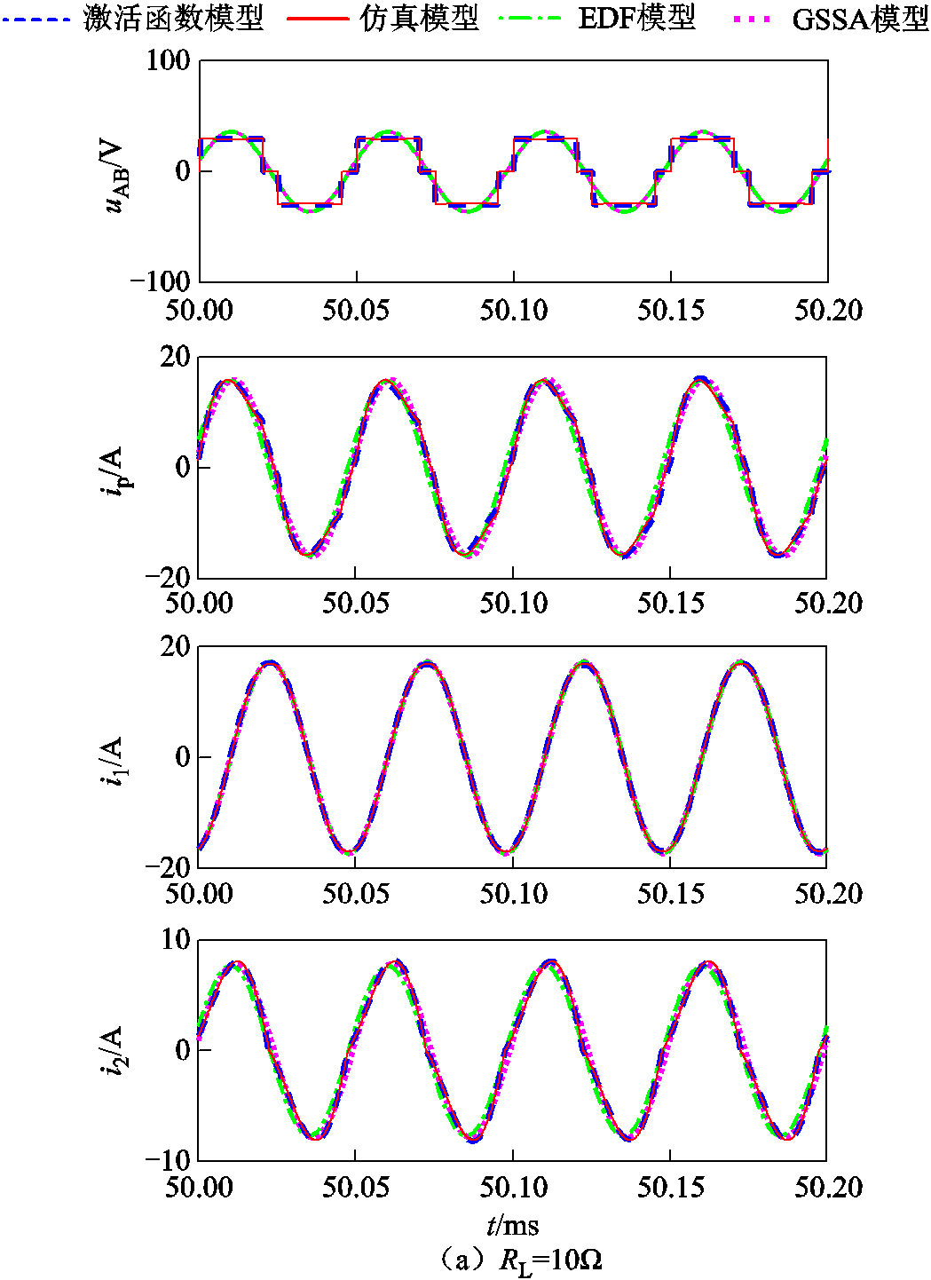
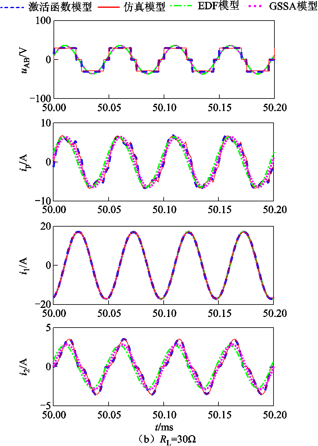
为了验证本文提出的基于激活函数的LCC-S型WPT系统模型的精确度,将激活函数模型与非线性时域仿真模型、EDF模型和GSSA模型的结果进行对比,其中在Matlab/Simulink中实现了非线性时域仿真模型,然后通过使用Matlab中的m文件来执行激活函数模型。LCC-S型WPT系统的激活函数模型中的陡度因子a设置为1 000。LCC-S型WPT系统在不同负载下的电压和电流仿真波形如图6所示。图6a中,φ=0.8π,RL=10Ω,流入整流二极管的电流i2处于连续模式;图6b中,φ=0.8π,RL=30Ω,流入整流二极管的电流i2处于断续模式。由图6可以看出,EDF模型及GSSA模型在断续模式下存在较大的误差,而激活函数模型可以准确地描述LCC-S型WPT系统的静态特性。
4.2 大信号模型验证
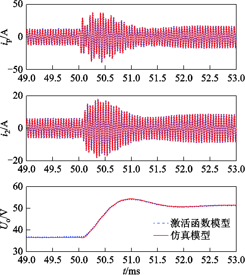
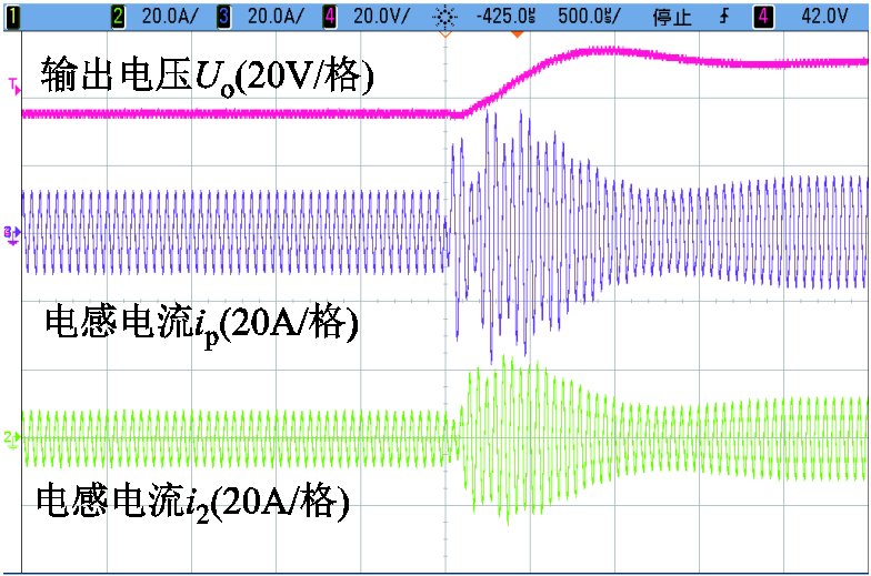
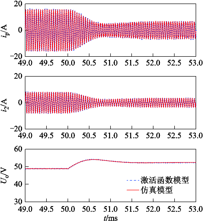
为了进一步验证3.1节中建立的激活函数模型,分别观察在移相角扰动和负载扰动条件下系统的动态响应。对于移相角扰动,在t=50ms时,移相角从0.5π跃升至π,负载电阻RL=10Ω。电感电流ip、i2和输出电压Uo的波形如图7所示,实验结果如图8所示。通过图7可以看出,激活函数模型的稳态和瞬态过程与Simulink电路仿真结果一致,同时与实验结果吻合。该结果表明,激活函数模型可以准确地描述系统的瞬态特性。
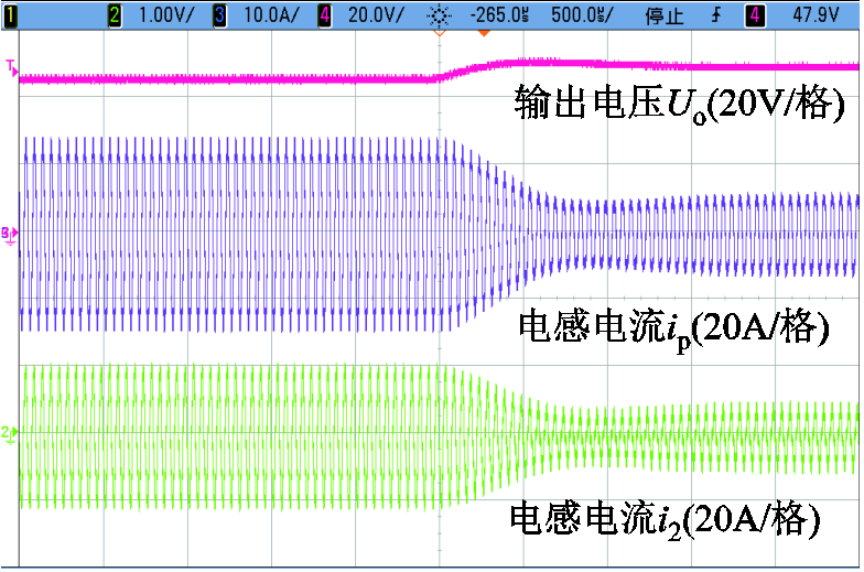
对于负载扰动,在t=50ms时,负载从10Ω跃升至30Ω,移相角保持0.8π。电感电流ip、i2和输出电压Uo的波形如图9所示,实验结果如图10所示。
由图9可以看出,系统从连续模式转换到断续模式,激活函数模型的稳态和瞬态过程与Simulink电路仿真结果一致,同时与实验结果吻合。该结果表明,激活函数模型可以准确地描述系统的瞬态特性。
综上所述,激活函数模型、仿真和实验结果十分吻合,验证了本文建立的激活函数模型的准确性。激活函数模型可以准确地预测系统的稳态和动态过程,对WPT系统动态性能分析,了解系统高速动态变化的电压电流应力情况,系统参数设计起到辅助作用。
4.3 稳定性验证
本节将利用3.2节建立的闭环模式下的激活函数模型进行稳定性分析,将模型计算结果与Simulink仿真结果和实验结果进行对比,以探究系统存在的不稳定现象。
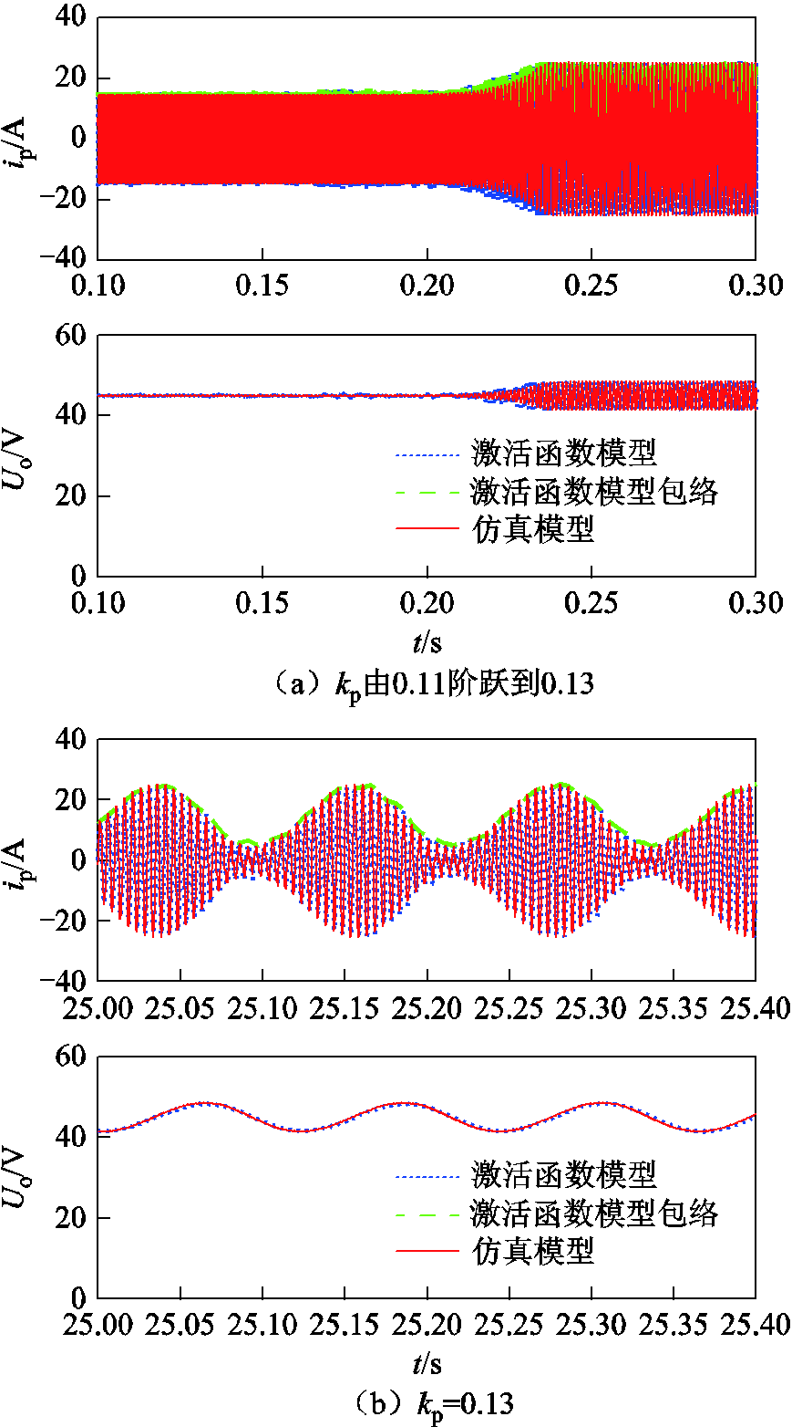
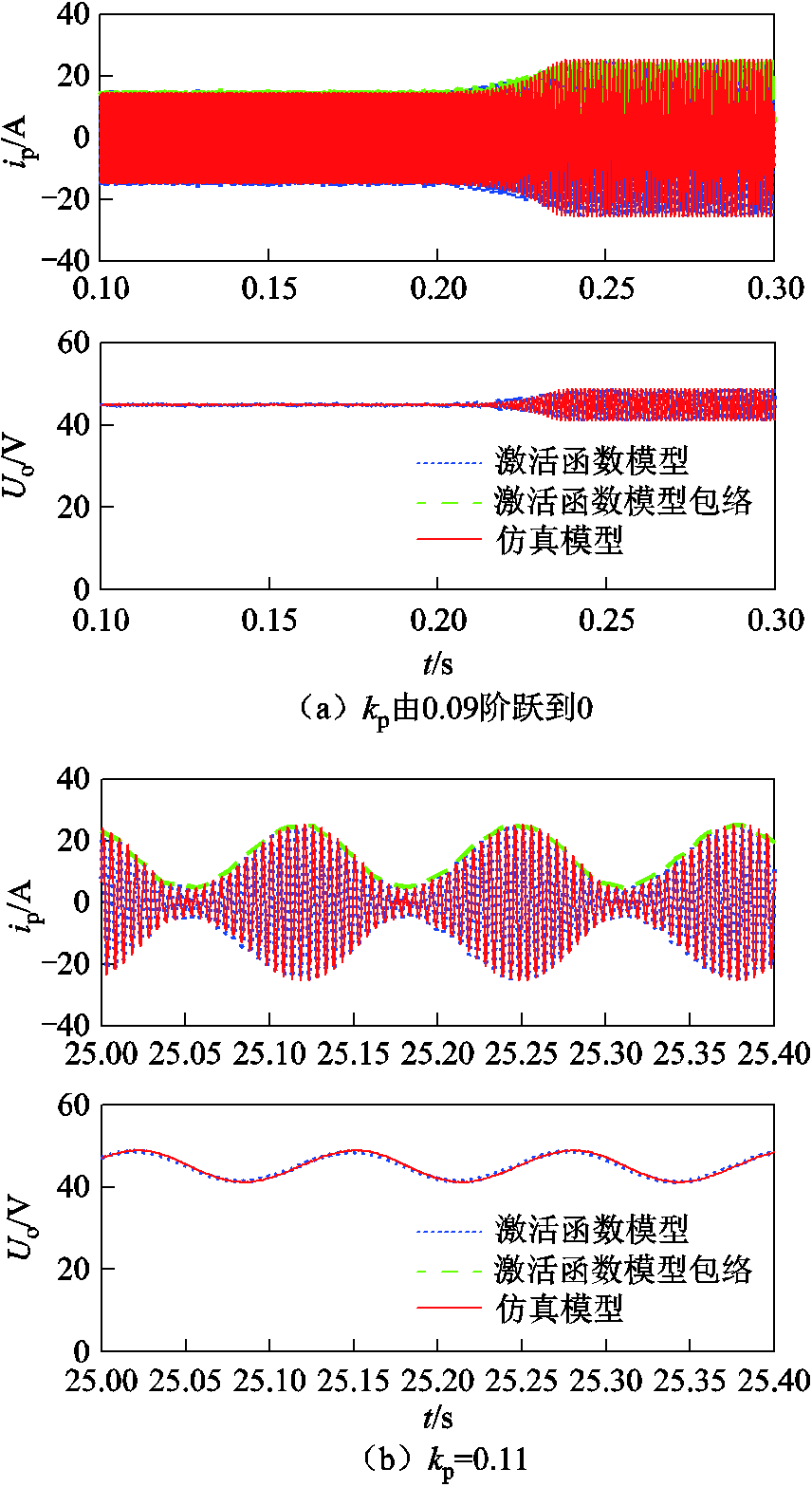
首先,研究了控制器参数变化时所提出的激活函数模型和时域仿真模型中系统稳定性的对比,结果如图11所示。在这两种模型中,延时时间Td为87μs,ki设置为10,t<0.2s时,kp为0.11,t=0.2s时kp由0.11阶跃至0.13。通过对比可以发现,比例系数kp增加,系统由稳定状态进入不稳定状态,出现低频振荡现象,同时激活函数模型和仿真模型具有相同的稳态和瞬态响应。对应的实验波形如图12所示,可以看出,激活函数模型、仿真模型和实验结果基本一致,证实了本文提出的激活函数模型的准确性及稳定性分析的有效性。
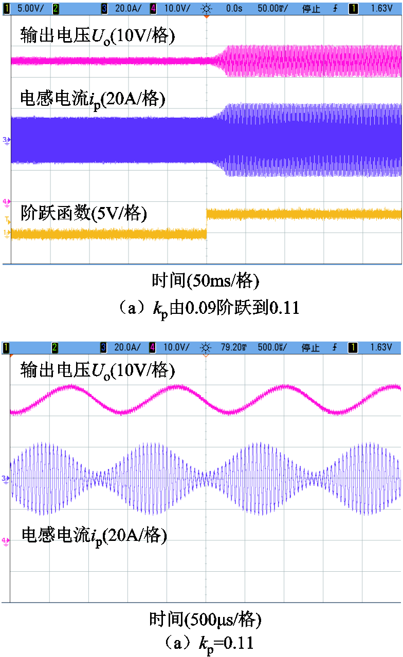
同理延时时间Td为87μs,ki=100,在t=0.2s时将kp由0.09阶跃变化为0.11。此时激活函数模型和时域仿真模型中ip和Uo的波形如图13所示。实验波形如图14所示。激活函数模型、仿真模型和实验结果基本一致。
由图11和图13可以发现,在积分系数一定的情况下,比例系数的增大可能会导致系统失稳;对比图11和图13可以发现,积分系数增加时,系统保持稳定状态的比例系数的范围减小。
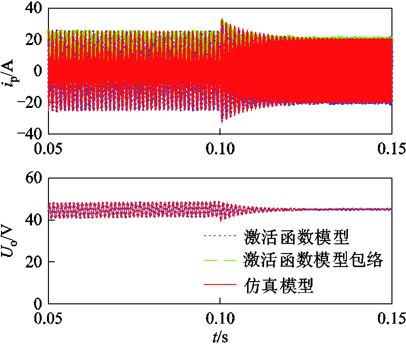
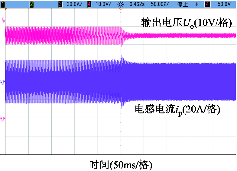
为了验证负载对系统稳定性的影响,进行负载阶跃实验。由图11可知,系统运行在kp=0.13,ki=10,RL=10Ω的工况时,系统处于不稳定运行状态。在此条件下,负载电阻从10Ω阶跃到7Ω,此时激活函数模型和仿真模型结果如图15所示。二者具有相同的稳态和瞬态响应。结果表明,当负载电阻减小,ip和Uo由不稳定状态过渡到稳定状态。实验结果如图16所示。因此,减小负载RL可以增加系统的稳定性。
本节激活函数模型、仿真模型和实验波形清楚地描绘了LCC-S型WPT系统的稳态和动态特性。当系统进入不稳定状态时,发生低频振荡,此时系统中电压和电流的幅值增大,这种现象会增加器件的应力,甚至损坏器件。
5 结论
本文通过引入S型激活函数,对不连续的开关变量进行连续处理,建立了LCC-S型WPT系统的大信号连续模型。所提出的模型具有以下优点:
1)利用激活函数建立的大信号模型不包括断续函数,例如符号函数、绝对值函数或方波。系统微分方程中的不连续函数由激活函数近似,以便使不连续部分连续。
2)该模型实现了对LCC-S型WPT系统的统一描述,以及对连续和断续模式的统一描述。该模型准确地描述了系统的稳态和动态特性。
3)通过建立的闭环模式下的激活函数模型,分析了控制器参数和系统参数对稳定性的影响。
本文提出利用激活函数建立LCC-S型WPT系统的模型和稳定性分析方法同样适用于任何其他补偿网络,可为系统参数和控制器参数设计提供指导。
参考文献
[1] 沈栋, 杜贵平, 丘东元, 等. 无线电能传输系统电磁兼容研究现况及发展[J]. 电工技术学报, 2020, 35(13): 2855-2869.
Shen Dong, Du Guiping, Qiu Dongyuan, et al. Research status and development trend of electromagnetic compatibility of wireless power transmission system[J]. Transactions of China Electrotecnical Society, 2020, 35(13): 2855-2869.
[2] 薛明, 杨庆新, 章鹏程, 等. 无线电能传输技术应用研究现状与关键问题[J]. 电工技术学报, 2021, 36(8): 1548-1567.
Xue Ming, Yang Qingxin, Zhang Pengcheng, et al. Application status and key issues of wireless power transmission technology[J]. Transactions of China Electrotecnical Society, 2021, 36(8): 1548-1567.
[3] 吴理豪, 张波. 电动汽车静态无线充电技术研究综述(下篇)[J]. 电工技术学报, 2020, 35(8): 1662-1678.
Wu Lihao, Zhang Bo. Overview of static wireless charging technology for electric vehicles: part Ⅱ[J]. Transactions of China Electrotecnical Society, 2020, 35(8): 1662-1678.
[4] Han Junfeng, Zhang Bo, Qiu Dongyuan, Bi-switching status modeling method for DC-DC converters in CCM and DCM operations[J]. IEEE Transactions on Power Electronics, 2017, 32(3): 2464-2472.
[5] Middlebrook R, Cuk S. A general unified approach to modelling switching power converter stages[C]//IEEE Power Electronics Specialists Conference, California, 1997: 18-34.
[6] 国玉刚, 崔纳新. LCC-S 型无线电能传输系统优化配置及特性研究[J].电工技术学报, 2019, 34(18): 3723-3731.
Guo Yugang, Cui Naxin. Research on optimal configuration and characteristics based on LCC-S type wireless power transfer system[J]. Transactions of China Electrotecnical Society, 2019, 34(18): 3723-3731.
[7] Ramezani A, Shahrokh F, Hossein I, et al. Optimized LCC-series compensated resonant network for stationary wireless EV chargers[J]. IEEE Transactions on Industrial Electronics, 2019, 66(4): 2756-2765.
[8] Hu Aiguo Patrick. Modeling a contactless power supply using GSSA method[C]//2009 IEEE International Conference on Industrial Technology, Gippsland, VIC, 2009: 1-6.
[9] 程志远, 邵会文, 陈坤, 等. 无线电能传输系统小信号模型降阶研究[J]. 电工技术学报, 2021, 36(24): 5143-5152.
Cheng Zhiyuan, Shao Huiwen, Chen Kun, et al. Research on order reduction of small signal model of wireless power transmission system[J]. Transactions of China Electrotecnical Society, 2021, 36(24): 5143-5152.
[10] Zahid Z, Zakariy D, Cong Z, et al. Modeling and control of series-series compensated inductive power transfer system[J]. IEEE Journal of Emerging and Selected Topics in Power Electronics, 2015, 3, (1): 111-123.
[11] Li Hongchang, Wang Kangping, Huang Lang, et al. Dynamic modeling based on coupled modes for wireless power transfer systems[J]. IEEE Transactions on Power Electronics, 2015, 30(11): 6245-625
[12] 高国庆, 雷万钧, 袁晓杰, 等. 双有源全桥变换器全状态离散迭代建模与输出电压纹波分析[J]. 电工技术学报, 2021, 36(2): 330-340.
Gao Guoqing,Lei Wanjun,Yuan Xiaojie,et al. Full-state discrete-time model and the output-voltage-ripple analysis of the dual active bridge converter[J]. Transactions of China Electrotecnical Society, 2021, 36(2): 330-340.
[13] Tahavorgar A, Quaicoe J. Stability and small signal analysis of the dual series-resonant DC-DC converter[J]. IEEE Transactions on Power Electronics, 2019, 34(2): 1420-1430.
[14] 张焕, 张庆, 于纪言. 激活函数的发展综述及其性质分析[J]. 西华大学学报(自然科学版), 2021, 40(4): 1-10.
Zhang Huan, Zhang Qing, Yu Jiyan. Overview of the development of activation function and its nature analysis[J]. Journal of Xihua University (Natural Science Edition), 2021, 40(4): 1-10.
[15] Lu Yimin, Huang Xianfeng, Huang Yizheng, et al. Sigmoid function model for a PFM power electronic converter[J]. IEEE Transactions on Power Electronics, 2020, 35(4): 4233-4241.
[16] Kim H, Son J, Lee J. A high-speed sliding-mode observer for the sensorless speed control of a PMSM[J]. IEEE Transactions on Industrial Electronics, 2011, 58(9): 4069-4077.
[17] Basterretxea K, Tarela J, del Campo I. Approximation of sigmoid function and the derivative for hardware implementation of artificial neurons[J]. IEEE Proceedings Circuits Devices and Systems, 2004, 151(1): 18-24.
[18] Richard J. Time-delay systems: an overview of some recent advances and open problems[J]. Automatica, 2003, 39(10): 1667-1694.
[19] Hu Jun, Wang Zidong, Gao Huijun, et al. Robust sliding mode control for discrete stochastic systems with mixed time delays, randomly occurring uncertainties, and randomly occurring nonlinearities[J]. IEEE Transactions on Industrial Electronics, 2012, 59(7): 3008-3015.
[20] Harnefors L, Antonopoulos A, Ilves K, et al. Global asymptotic stability of current-controlled modular multilevel converters[J]. IEEE Transactions on Power Electronics, 2015, 30(1): 249-258.
[21] 贾宏杰. 电力系统时滞稳定性[M]. 北京: 科学出版社, 2016.
[22] 郭春义, 彭意, 徐李清, 等.考虑延时影响的 MMC-HVDC系统高频振荡机理分析[J]. 电力系统自动化, 2020, 44(12): 119-126.
Guo Chunyi, Peng Yi, Xu Liqing, et al. Analysis on high-frequency oscillation mechanism for MMC-HVDC system considering influence of time delay[J]. Automation of Electric Power Systems, 2020, 44(12): 119-126.
[23] Dong Chaoyu, Yang Shunfeng, Jia Hongjie, et al. Padé-based stability analysis for a modular multilevel converter considering the time delay in the digital control system[J]. IEEE Transactions on Industrial Electronics, 2019, 66(7): 5242-5253.
[24] Li Hongyi, Wang Lijie, Du Haiping, et al. Adaptive fuzzy back stepping tracking control for strict-feedback systems with input delay[J]. IEEE Transactions on Fuzzy Systems, 2017, 25(3): 642-652.
[25] 陈锦洲,陈磊,陈亦平, 等. 基于Pade近似的电力系统频率振荡模式延时轨迹分析[J]. 电力系统自动化, 2019, 43(14): 120-125.
Chen Jinzhou, Chen Lei, Chen Yiping, et al. Trajectory analysis of time delay for frequency oscillation mode of power system based on Pade approximation[J]. Automation of Electric Power Systems, 2019, 43(14): 120-125.
Modeling and Stability Analysis of Wireless Power Transfer System with an LCC-S Compensated Network Based on Activation Function
Hu Xiufang Wang Yue Lü Shuangqing Zhao Delin Ma Tianlu
(State Key Laboratory of Electrical Insulation and Power Equipment Xi’an Jiaotong University Xi’an 710049 China)
Abstract Wireless power transfer (WPT) system based on power electronic devices is a switching system, its large-signal model is the basis for studying the operating characteristics and stability of the system. The key to modeling is how to describe the nonlinear and discrete switch variables in the system. In this paper, a modeling method based on sigmoid activation function is proposed to solve this problem. Since the sigmoid activation function is continuous, smooth, differentiable, and saturated at a certain value. Therefore, a sigmoid activation function with a large steepness factor is used to approximate the switching process of the switch, the WPT system is transformed from a discrete switching system to a continuous system. An LCC-S compensated WPT system is selected as an example, and its sigmoid function model in open-loop and closed-loop mode is constructed. However, in closed-loop control mode, the time delay in digital control system is often ignored. Delay link makes WPT system more complicated. For systems without time delay, a certain mapping relationship can be established between input and output. But the existence of time delay may disturb this specific relationship. For the same sampled signal, the time delay in digital control system may lead to the instability of WPT system. The performance of WPT system will inevitably be affected or even deteriorated. Therefore, it is necessary to analyze the stability considering the influence of time delay.
In order to avoid these problems, approximating the time delay in stability analysis becomes a preferred solution. Time delay can be approximated by first-order lag, Taylor expansion, Pade approximation, etc. Compared with the first-order lag and Taylor series, Pade approximation has better performance because of its rational polynomial form. In addition, Pade approximation can handle a relatively short delay. Because the time delay of digital control system is in the order of microseconds, Pade approximation may be more appropriate. Based on the fifth-order pade equivalent approximate delay link, a closed-loop model is established to reveal the instability in the system. The influence of controller parameters and system parameters on transient behavior and stability are analyzed.
In addition, the simulation and experimental platform of the LCC-S compensated WPT system are built in this paper, and the simulation and experimental results verify the validity of the above-derived model. The large signal model established by activation function does not include discontinuous functions, such as sign function, absolute value function or square wave. The discontinuous function in the differential equation of the system is approximated by the activation function in order to make the discontinuous part continuous. From continuous mode to discontinuous mode, the steady and transient processes of the activation function model are consistent with the simulation results of simulation and the experimental results. The results show that the activation function model can accurately describe the transient characteristics of the system. The generalized state-space averaging (GSSA) and extended describing function (EDF) models which are commonly used in WPT systems are compared with model established by activation function, the results show that the model established by activation function model has higher accuracy.
When the system enters into an unstable state, low-frequency oscillation occurs. At this time, the amplitude of voltage and current in the system increases. This phenomenon will increase the stress of the device, or even damage the device. The activation function model, simulation model and experimental waveform in this section clearly describe the steady-state and dynamic characteristics of LCC-S compensation WPT system.
Keywords: Wireless power transfer, LCC-S compensation topology, activation function, large signal model, stability
DOI:10.19595/j.cnki.1000-6753.tces.211722
中图分类号:TM724
收稿日期 2021-10-29
改稿日期 2022-01-05
作者简介
胡秀芳 女,1986年生,博士研究生,研究方向为无线电能传输系统建模和控制。E-mail:huxiufang029@stu.xjtu.edu.cn
王 跃 男,1972年生,教授,博士生导师,研究方向为无线电能传输技术、双有源全桥DC-DC变换器、模块化多电平换流器、虚拟同步发电机。E-mail:davidwangyue@mail.xjtu.edu.cn(通信作者)
(编辑 赫 蕾)
 (1)
(1)
 (2)
(2)
 (3)
(3)
 (11)
(11)
 (13)
(13)
 (15)
(15)
 (18)
(18)
 (19)
(19)
 (27)
(27)
 (28)
(28)
 (30)
(30)
 (32)
(32)
 (33)
(33)
 (36)
(36)