 ”为估计值,上标“m”为解调后的量,下标“h”为高频分量,下标“pu”为归一化后的量,下标“s”为a~f相的量,ab 表示两相静止坐标系,dq表示两相旋转坐标系,z1z2表示谐波空间坐标系。
摘要 对于永磁同步电机(PMSM)而言,高频信号注入法是一种有效的零低速无位置传感器控制方法。然而,注入的高频信号会带来严重的可听噪声问题,无法满足舰船推进等高端领域的应用要求。为此,该文提出随机频率三角波电压注入无位置传感器控制方法,解决了PMSM的噪声问题。以两个不同频率的三角波电压信号为基础,遵循伏秒面积相等原则,通过线性同余法生成随机数进行选择,合成随机频率的三角波电压信号。同时,将该随机频率信号注入到估计的转子参考系中,可以有效降低注入频率处的最大噪声,并拓展高频电流的功率谱密度(PSD),从而降低高频电流引起的可听噪声。此外,为了从感应电流中获取转子位置信息,提出了一种对应的信号解调方法。实验验证了该方法的可行性和有效性。
关键词:永磁同步电机 随机频率 三角波 噪声 功率谱密度
多相永磁电机具有高功率密度、高转矩密度、高母线电压利用率等优点,被广泛应用于舰船推进等高端领域[1-5]。相较于传统的正六相电机,相移30 °的双三相永磁同步电机(Dual Three Phase Permanent Magnet Synchronous Motor, DTP-PMSM)在绕组因数、转矩性能等方面具有更大的优势,受到了越来越多的关注[6]。为了实现永磁同步电机高性能控制,电机的转子位置信息不可或缺。转子位置信息通常由机械安装的位置传感器获得,但会增加成本和质量,降低系统可靠性[7]。为解决这一问题,相关学者开展了无位置传感器控制策略研究。
无位置传感器控制可分为两种,即适用于中高速的反电动势或磁链法和适用于零低速的高频信号注入法[8]。高频信号注入法根据注入坐标系不同,可分为两相静止坐标系下的旋转注入法和旋转坐标系下的脉振注入法。此外,根据注入信号不同,又可分为正弦波注入法和方波注入法[9]。虽然高频信号注入法能实现零低速下的位置估计,但是会产生高频噪声,限制了该方法在低噪声领域的应用。为了解决这一问题,相关学者开展了大量的研究工作。目前,降低高频噪声的方法可分为三类:减小注入信号幅值、调整注入信号的频率和随机注入。
减小注入信号幅值是降低信号注入产生的高频噪声最简单直接的方法。文献[10]提出了一种分析模型法来选择注入高频电压的幅值,以最大可接受的位置误差来降低注入电压幅值。然而,降低注入高频电压的幅值,会使得高频响应电流信号的信噪比也随之降低,导致估计的位置角不准确。文献[11]借助现场可编程门阵列(Field Programmable Gate Array, FPGA)和Delt/Sigma采样技术实现了低注入幅值下的位置角提取,但这种方法对硬件条件要求较高。
人耳听觉范围为20 Hz~20 kHz,调整注入信号的频率也可以降低噪声的影响。文献[12]将注入信号频率提高到PWM开关频率,但高频损耗会大大增加。文献[13]提出了一种低频电流注入法,但该方法需要设计额外的控制器,结构相对复杂。文献[14]将注入频率降低到50 Hz,实现了降低噪声的效果。但是,低频响应电流和基频电流不容易分离,系统动态性能也较差。
随机注入的思想来源于随机脉宽调制,主要思路是通过随机化频率降低高频噪声[15-16]。文献[17]提出了一种方波频率不变、相位随机化的注入方法。文献[18]提出了一种方波频率随开关频率同时随机变化的降噪方法。文献[19]提出了一种双随机注入方法,频率与相位同时随机变化,进一步降低了高频噪声。文献[20-21]提出了随机频率正弦波注入法以降低高频噪声。但是,正弦波和方波在注入频率处的最大噪声相对较大,难以满足要求。
为解决最大噪声问题,本文提出一种基于随机频率高频三角波电压注入的无位置传感器控制方法。首先,提出一种新的注入波形,即采用三角波电压注入,来降低注入频率处的最大噪声。同时,为了降低固定频率注入产生的高频噪声,利用随机化方法选择三角波电压进行注入,并提出信号的解调方法。此外,阐述该方法降噪的机理,即对所提出方法的功率谱密度(Power Spectral Density, PSD)理论进行了分析。最后,在DTP-PMSM实验平台上验证了该方法的可行性和有效性。
两种不同频率的三角波电压随机注入到估计的转子参考系中,在电机中感应出高频电流分量,从该分量中解调出转子位置信息和转速,实现低速下的无位置传感器控制,整体控制框图如图1所示。图中,n、i、u、qe分别为电机的转速、电流、电压、转子位置角,上标“*”为给定值,上标“”为估计值,上标“m”为解调后的量,下标“h”为高频分量,下标“pu”为归一化后的量,下标“s”为a~f相的量,ab 表示两相静止坐标系,dq表示两相旋转坐标系,z1z2表示谐波空间坐标系。
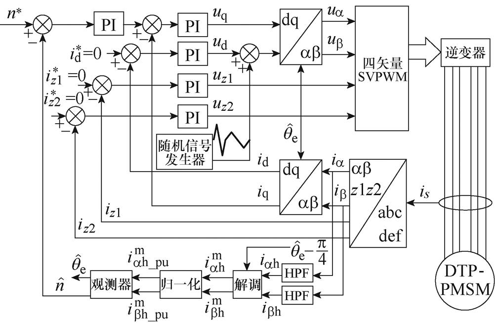
图1 整体控制框图
Fig.1 Overall control block diagram
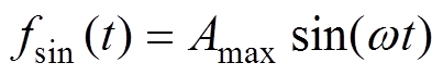
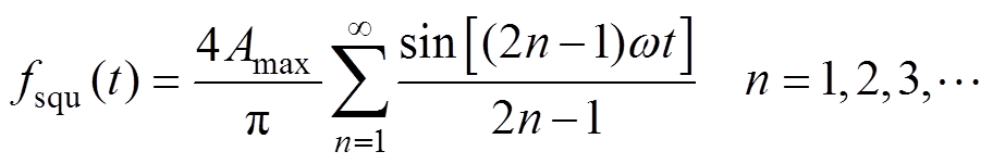
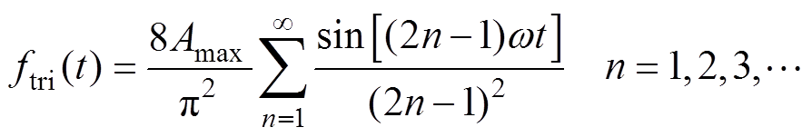
在一个周期内,正弦波、方波和三角波的波形如图2所示,式(1)~式(3)为三种波形的傅里叶分解式。
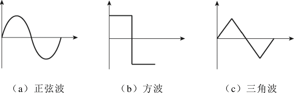
图2 注入信号波形
Fig.2 Injection signal waveforms
 (1)
(1)
 (2)
(2)
 (3)
(3)
式中,fsin(t)、fsqu(t)、ftri(t)分别为正弦波、方波、三角波的傅里叶分解式;Amax为注入幅值;w 为注入角频率。
可知,当注入信号幅值相同时,三角波信号具有最小的基频分量。因此,采用三角波注入可以降低注入频率处的最大噪声。
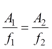
同时,为了降低固定频率注入带来的噪声,采用随机频率三角波电压信号进行注入,即两种不同频率随机交替的三角波电压信号,注入电压波形及感应电流波形如图3所示。为了保证感应电流幅值相等,使得控制系统更稳定,如式(4)所示,注入频率与注入幅值之比应相等。
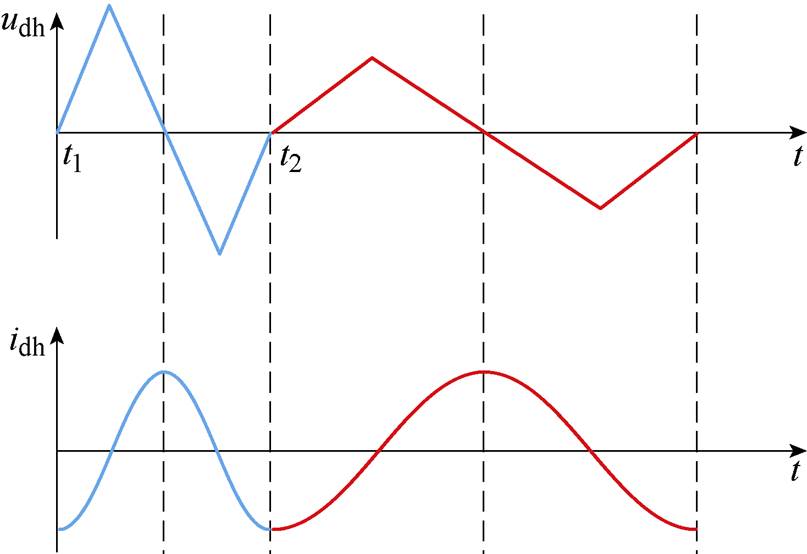
图3 注入电压波形及感应电流波形
Fig.3 Injection voltage waveform and induced current waveform
 (4)
(4)
式中,f1、f2为两个注入信号的频率;A1、A2为两个注入信号的幅值。
在传统的位置解调方法中,往往通过解调信号与高频电流相乘实现解调。由于数字控制系统中存在1.5个采样周期的延迟,这会使得高频电流与解调信号相位失配,从而增大位置估计误差。为解决该问题,提出一种不需要解调信号的观测器,使得系统抗延时性更强。
观测器整体结构分为三部分:信号解调、归一化和锁相环。首先,通过高通滤波器提取高频感应电流分量。其次,通过两次旋转变换和绝对值化对信号进行解调,省去了外部输入的解调信号,提高了抗延时性。然后,通过归一化消除注入幅值和相关参数等的影响。最后,通过正交锁相环求得位置角。观测器结构框图如图4所示。图中, 为估计的电角速度,e 为位置误差信号,T为旋转变换矩阵。
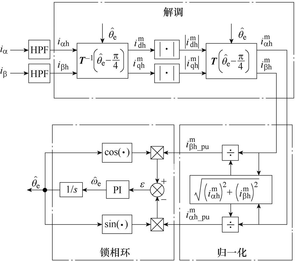
图4 观测器结构框图
Fig.4 Structure block diagram of observer
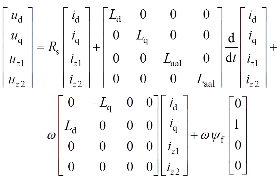
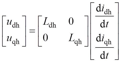
DTP-PMSM在旋转坐标系下的模型如式(5)所示,分为基波空间dq和谐波空间z1z2。谐波空间的电流不参与机电能量转换,可以被忽略。当电机低速运行时,转速较小,与转速相关的反电动势项和交叉耦合项都可以被忽略。当高频信号注入电机时,感抗为主要部分,电阻项也可以被忽略。综合以上分析,将电机模型等效为如式(6)所示的高频纯电感模型。
 (5)
(5)
式中,ud、uq、uz1和uz2分别为dq轴和z1z2轴的电压;id、iq、iz1和iz2分别为dq轴和z1z2轴的电流;Ld、Lq和Laal分别为dq轴电感和漏感;yf为永磁磁链;Rs为绕组电阻。
 (6)
(6)
式中,udh和uqh分别为d、q轴的高频电压;idh和iqh分别为d、q轴的高频电流;Ldh和Lqh分别为d、q轴的高频增量电感。
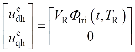
在估计d轴上注入随机频率三角波电压,有
 (7)
(7)
 (8)
(8)
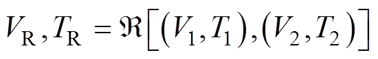
式中, [ ]为每完成一个注入周期便进行一次随机选择;
 和
和 分别为估计d、q轴的高频电压;VR为随机三角波电压的幅值;TR为随机三角波电压的周期;V1和T1分别为第一种三角波的幅值和周期;V2和T2分别为第二种三角波的幅值和周期;
 为单位三角波函数,有
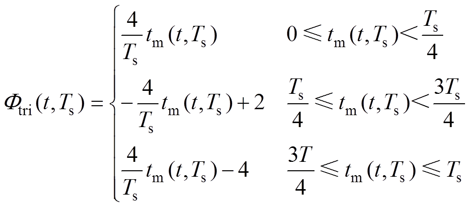 (9)
(9)
式中,Ts为三角波的周期;tm(t,Ts)为t除以Ts的余数。
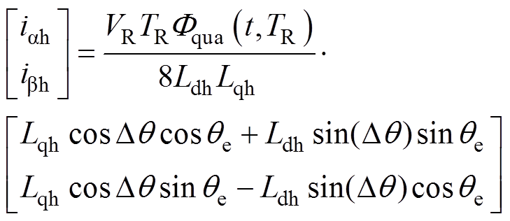
结合式(6)和式(7),得到静止坐标系下的表达式为
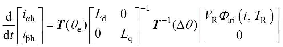 (10)
(10)
式中,iah和ibh分别为 轴的高频电流;
 为位置估计误差;
 为实际位置角,
 为估计位置角,且
 ;T(q )为
 (11)
(11)
积分后得到两相静止坐标系下的电流响应为
 (12)
(12)
式中, 为单位感应电流波形函数,有
 (13)
(13)
定义测量参考系dmqm,该参考系滞后于估计参考系45 °,将感应电流投影到该参考系中,有
 (14)
(14)
其中
式中, 和
和 为测量参考系下的高频电流。
当位置误差足够小时,式(14)简化为
 (15)
(15)
对式(15)进行绝对值化,由于Lqh>DL,所以Lqh±DLsin(2Dq)>0,进而得到
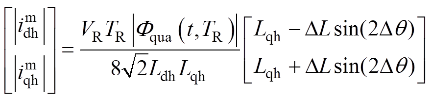 (16)
(16)
再将式(16)投影到两相静止坐标系中,有
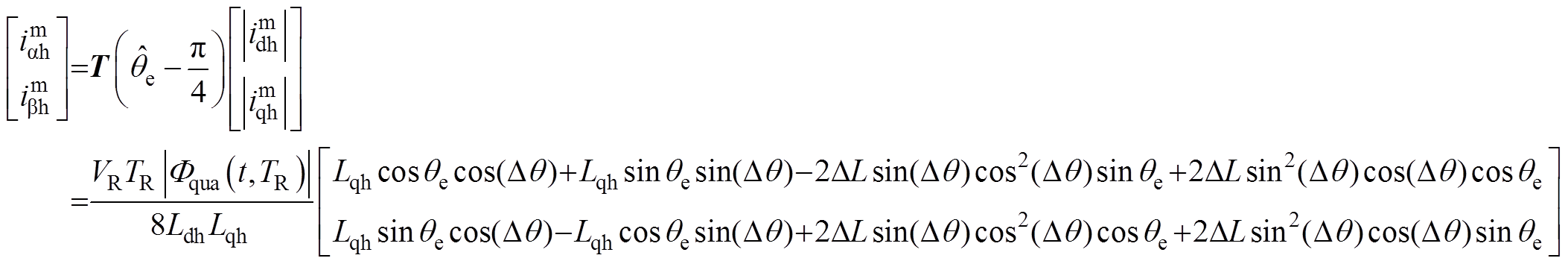 (17)
(17)
式中, 和
和 分别为解调后的轴高频电流。
当位置误差足够小时,式(17)简化为
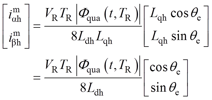 (18)
(18)
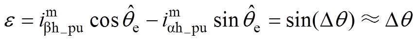
为了减小注入幅值和相关参数等对位置估计的影响,对式(18)进行归一化处理
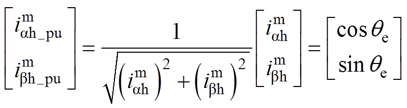 (19)
(19)
式中, 和
和 分别为归一化后的轴解调高频电流。
通过一个正交锁相环,得到位置误差信号e 为
 (20)
(20)
最后,通过一个比例积分控制器得到估计的电角速度,对电角速度进行积分得到估计的位置角。
PSD是信号自相关函数的傅里叶变换,也是随机信号分析的一项重要工具。通过对固定频率三角波注入和随机频率三角波注入法分别进行PSD分析,可以揭示随机频率三角波注入法的降噪机理。
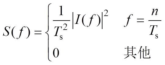
固定频率三角波电压注入法会产生固定频率的感应电流,固定频率感应电流的PSD表示为
 (21)
(21)
式中, 为PSD表达式;f为三角波的倍频;n为正整数;
 为一个周期内三角波电压注入所感应电流信号的傅里叶变换,有
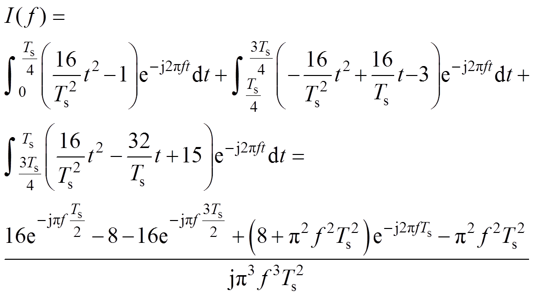 (22)
(22)
将f=n/Ts代入式(22),进一步得到
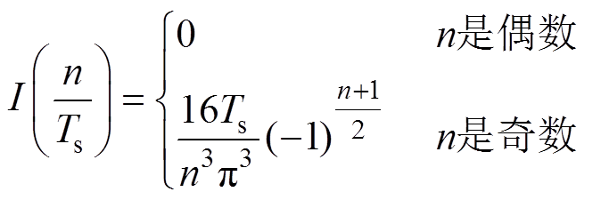 (23)
(23)
从式(23)可以看出,对于固定频率三角波电压注入法,感应电流的PSD只存在离散谱,且集中于注入频率及其奇数倍处。
随机频率三角波电压注入会产生随机频率的感应电流,其PSD可以表示为
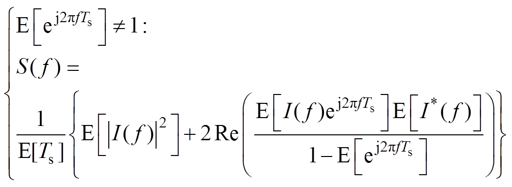 (24)
(24)
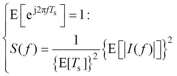 (25)
(25)
式中,E[ ]为数学期望算子; 为的共轭方程。经过上述分析可知,随机频率电流的PSD由两部分组成:式(24)为连续谱、式(25)为离散谱。离散谱会产生尖锐噪声,是降噪的关键。
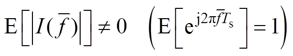
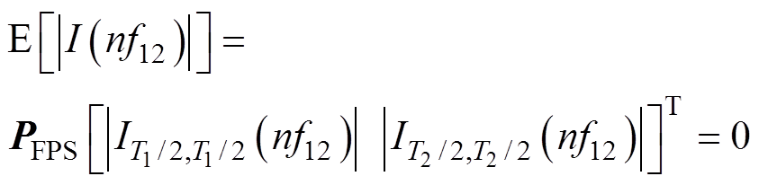
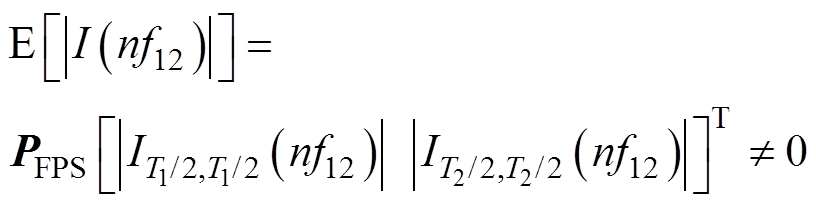
由式(25)可知,当满足以下条件时,会出现离散谱
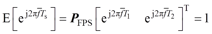 (26)
(26)
式中, 为方程的解;PFPS=[0.5 0.5]为概率矩阵,表示两种不同频率电流概率相等。换言之,当式(27)成立时,会出现离散谱
 (27)
(27)
由于 ≤1且
≤1且 ≤1,可得以下等效表述:
(1)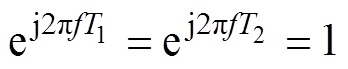 成立。
成立。
(2)fT1、fT2均为整数。
(3)f12为f1和f2的公倍数,f1、f2分别为T1和T2的倒数,f1与f2之比为
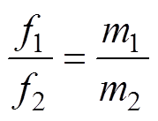 (28)
(28)
式中,m1与m2为注入两频率的最简整数比,且f12= f1m2=f2m1,所以式(26)的解为: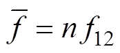 。其中,n为正整数,且其奇偶性影响式(25)的结果。
(1)n为偶数。f为f12的整数倍时,可以得到
 (29)
(29)
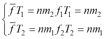
从式(29)可得,当n为偶数时,nm1和nm2均为偶数。将式(29)代入式(22),可得
 (30)
(30)
进一步可得
 (31)
(31)
因此,离散谱不会在两个注入信号频率的最小公倍数的偶数倍时出现。
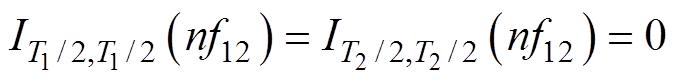
(2)n为奇数。因为m1和m2中至少有一个奇数,所以由式(29)可得, 、
、 中也至少有一个奇数,进而得到
 (32)
(32)
最终得出如下结论:对于随机频率三角波电压注入法,感应电流的PSD同时存在连续谱和离散谱,离散谱存在于两个注入信号频率的最小公倍数的奇数倍处。此外,由于随机注入的方式扩展了电流的PSD,使得一部分离散谱扩展为连续谱,所以离散谱峰值会降低。因此,相较于固定频率注入,随机频率三角波注入可以降低高频噪声。
所提出的随机频率高频三角波电压注入法在一台DTP-PMSM实验平台上进行了验证,表1为电机实验参数。所搭建的DTP-PMSM实验平台如图5所示,本实验采用TMS320F28377作为主控芯片。实际速度和位置由磁阻式旋转变压器获得,且仅用于比较。电机加载装置由磁粉制动器完成,实验数据通过高性能信号分析示波器(YOKOGAWA DLM2304)采集。注入的两种三角波频率分别为625 Hz和312.5 Hz,幅值分别为100 V和50 V。随机数通过线性同余法产生,两种注入信号的概率相同,均为50 %。
表1 DTP-PMSM实验参数
Tab.1 Experimental parameters of DTP-PMSM
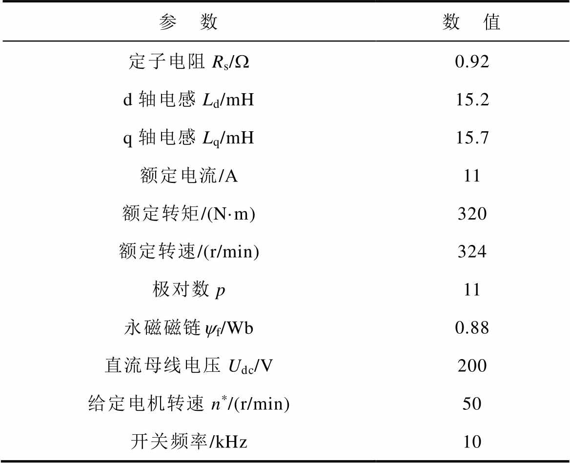
参 数数 值 定子电阻Rs/W0.92 d轴电感Ld/mH15.2 q轴电感Lq/mH15.7 额定电流/A11 额定转矩/(N·m)320 额定转速/(r/min)324 极对数p11 永磁磁链yf/Wb0.88 直流母线电压Udc/V200 给定电机转速n*/(r/min)50 开关频率/kHz10
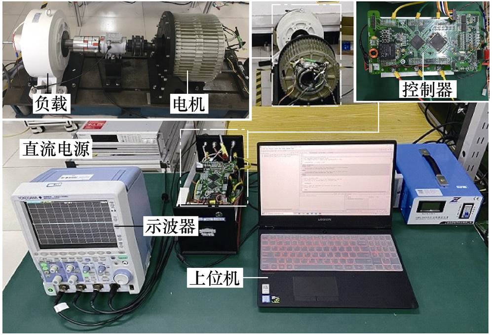
图5 DTP-PMSM实验平台
Fig.5 Experimental platform of DTP-PMSM
图6为注入的随机三角波电压和感应电流波形,两种不同频率的三角波电压随机注入电机,遵循伏秒面积相等原则,感应出两种不同频率的电流,且幅值相等。
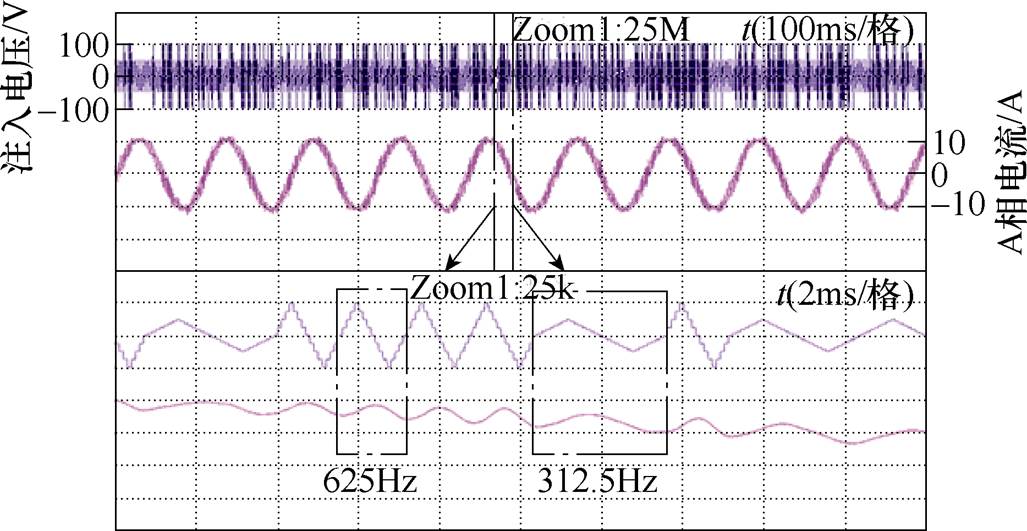
图6 注入电压及感应电流
Fig.6 Injection voltage and induced current
图7为空载时固定频率与随机频率下三种注入波形的快速傅里叶变换(Fast Fourier Transform, FFT)实验结果。312.5 Hz下的三种注入波形幅值均为50 V,则625 Hz下的三种注入波形幅值均为100 V。由图7a~图7c可以看出,312.5 Hz时的方波、正弦波和三角波在注入频率处的谐波分量分别为1.88 A、1.38 A、1.05 A;由图7d~图7f可以看出,625 Hz时的方波、正弦波和三角波在注入频率处的谐波分量分别为1.48 A、1.43 A、1.33 A;固定频率时三角波的基频分量低于传统正弦波和方波。由图7c、图7f、图7i可以看出,相比于固定频率三角波注入,随机三角波注入分散了频谱,降低了频谱峰值。由图7g~图7i可以看出,随机方波,随机正弦波和随机三角波在两个注入信号频率的最小公倍数处产生频谱尖峰,分别为0.56 A、0.48 A、0.43 A,随机三角波同样具有最小的基频分量。
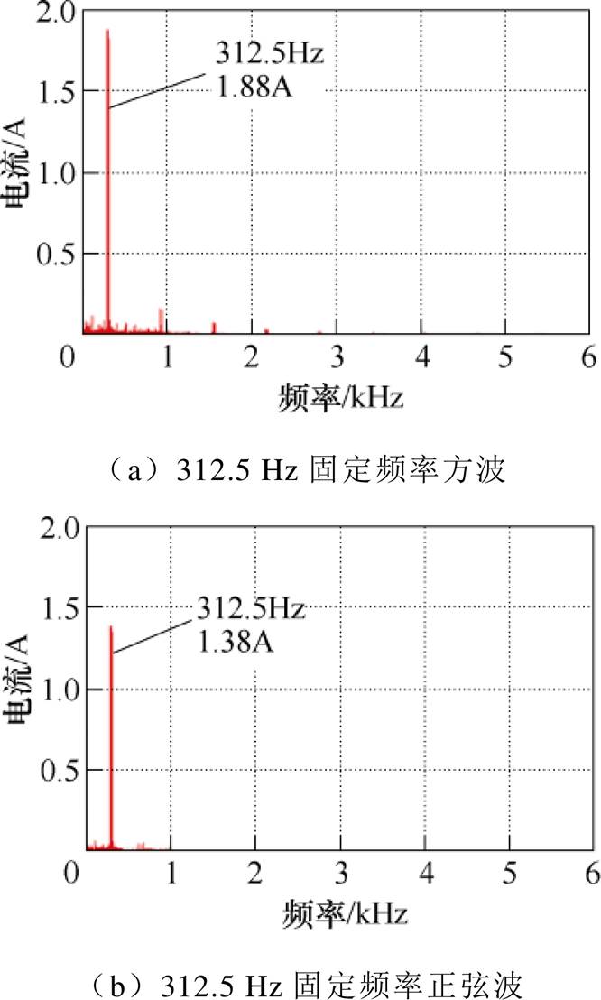
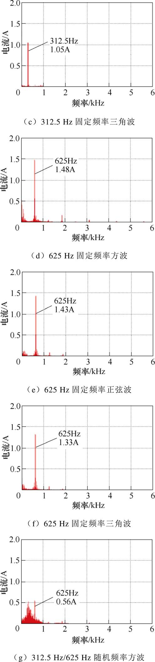
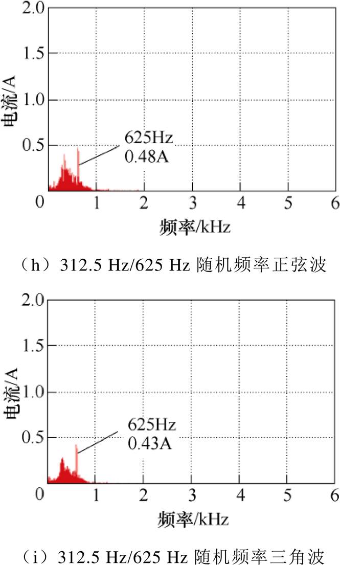
图7 FFT分析
Fig.7 FFT analysis
PSD可直观呈现一段频谱上的能量分布,随机注入可将注入频率及其奇数倍处的谐波分散,反映到PSD波形上,即频谱上突出的尖峰变得连续。因此,通过观察PSD波形,即可判断所采用的随机注入算法是否具有良好的降噪效果[22-25]。图8为空载时固定频率与随机频率下三种注入波形的PSD实验结果,表2列出了各频率下的具体结果。对于固定频率注入,可以看出,任何注入波形都会在注入频率处产生最大噪声。由图8a~图8c并结合表2可以看出,312.5 Hz时的方波、正弦波和三角波最大噪声分别为2.3 dB、-0.1 dB、-2.7 dB;由图8d~图8f并结合表2可以看出,625 Hz时的方波、正弦波和三角波最大噪声分别为1.4 dB、0.8 dB、-0.8 dB,固定频率时三角波的最大噪声低于传统正弦波和方波。由表2可以看出,随机三角波在312.5 Hz和937.5 Hz这两处的噪声低于固定312.5 Hz三角波注入,且在625 Hz和1 875 Hz这两处的噪声低于固定625 Hz三角波注入。由图8c、图8f、图8i可以看出,对于固定频率312.5 Hz和625 Hz三角波注入,PSD结果为集中在注入频率及其奇数倍处的尖峰,为离散谱;而对于随机频率312.5 Hz/625 Hz三角波注入,PSD尖峰下降,且尖峰周边的幅值有所增加,为连续谱,使得PSD分布更宽,所以相比于固定频率三角波注入,随机三角波注入拓宽了电流的PSD,离散尖峰下降,噪声降低。由图8g~图8i并结合表2可以看出,随机方波、随机正弦波和随机三角波在两个注入信号频率的最小公倍数处产生最大噪声,分别为-6.6 dB,-8.2 dB,-10.6 dB,随机三角波同样具有最低的最大噪声。
图9为中载50 r/min时电机运行的实验结果,此时的相电流峰值为5.5 A,位置估计误差约为8 °,速度估计误差约为5 r/min,误差较低,控制性能较好。图10为满载50 r/min时电机运行的实验结果,此时的相电流峰值为11 A,位置估计误差约为14 °,速度估计误差约为6 r/min,控制性能良好。图11为动态变速实验,给定转速从50 r/min变为-50 r/min,再变回50 r/min,最大位置误差约为20 °,最大速度误差约为7 r/min,电机转速和位置信息能够跟踪给定,动态性能较好。
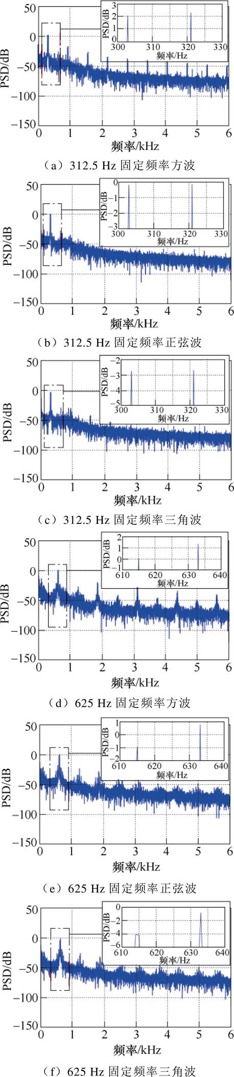
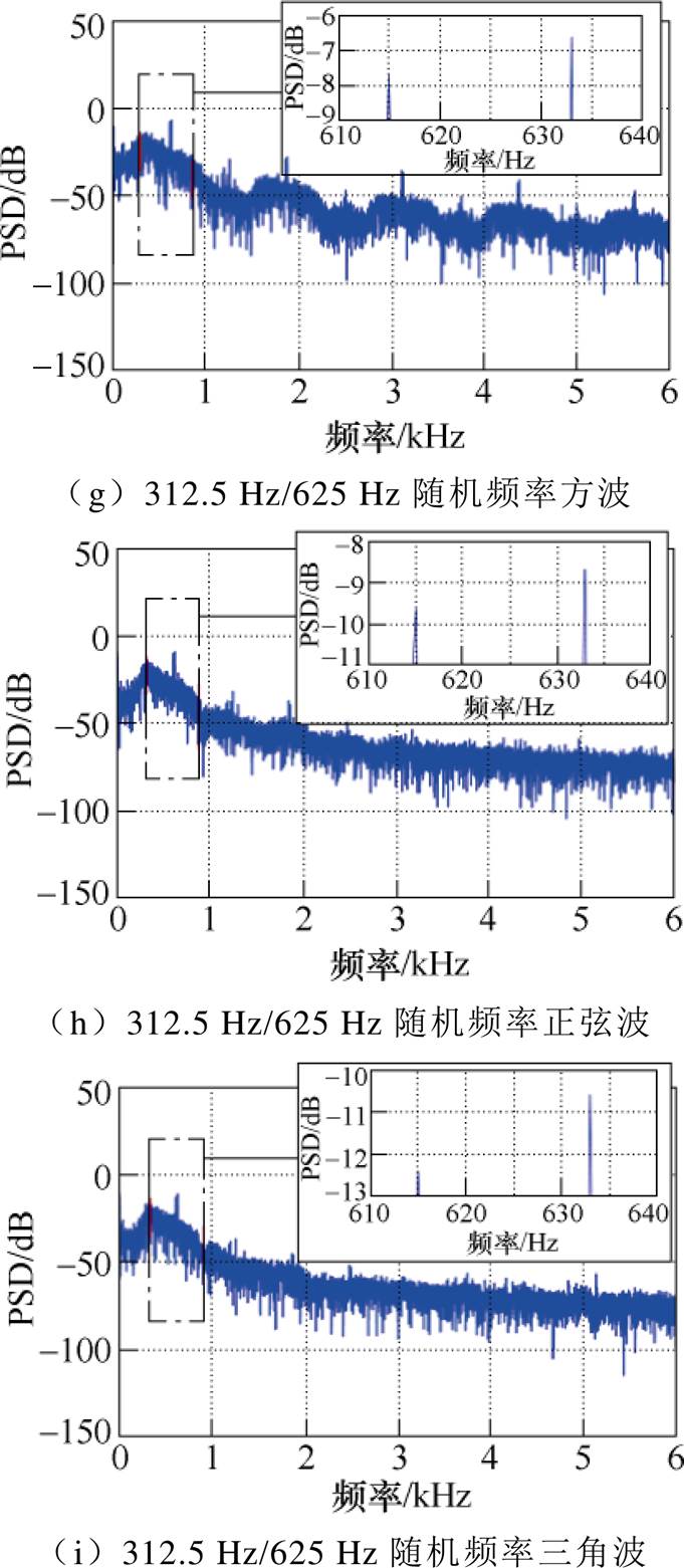
图8 PSD分析
Fig.8 PSD analysis
表2 电流PSD比较
Tab.2 Comparison of current PSD

注入形式注入频率/HzPSD/dB 312.5 Hz625 Hz937.5 Hz1 875 Hz 方波固定312.52.3-25.0-16.3-53.5 固定625-41.51.4-40.8-19.3 随机312.5/625-39.3-6.6-43.6-28.8 正弦波固定312.5-0.1-27.4-34.5-65.7 固定625-51.20.8-46.1-27.5 随机312.5/625-28.6-8.2-48.5-37.0 三角波固定312.5-2.7-28.3-29.0-61.7 固定625-40.7-0.8-44.4-31.3 随机312.5/625-22.5-10.6-45.9-45.3
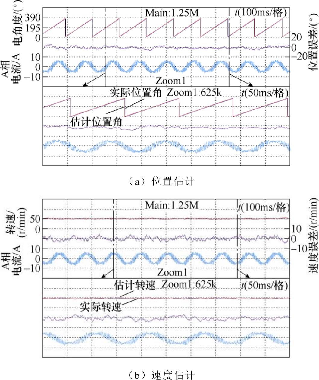
图9 中载运行
Fig.9 Medium load operation
图10 满载运行
Fig.10 Full load operation
本文针对高频注入法无位置传感器控制的高频噪声相关问题,提出PMSM随机频率高频三角波电压注入法。该方法将三角波形式的高频电压信号注入到估计的转子参考系中,降低注入频率处的最大噪声。此外,为了解决固定频率注入带来的噪声问题,采用随机频率三角波注入法,拓宽了相电流的PSD,降低了离散谱峰值,使得高频噪声降低。从感应的高频电流中解调出转速和位置角信息,实现低速下的无位置传感器控制。实验结果表明,高频三角波电压注入法降低了注入频率处的最大噪声,且通过随机化注入电压的频率,降低了高频噪声。同时,随机三角波的最大噪声也低于传统随机正弦波和随机方波。
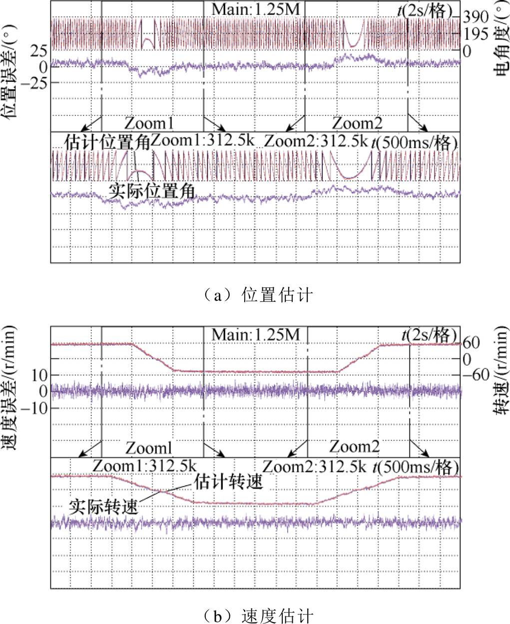
图11 变速运行
Fig.11 Variable speed operation
参考文献
[1] Zhang Zhifeng, Wu Yue, Su Hequn, et al. Research on open-circuit fault tolerant control of six-phase per- manent magnet synchronous machine based on fifth harmonic current injection[J]. CES Transactions on Electrical Machines and Systems, 2022, 6(3): 306- 314.
[2] 赵勇, 黄文新, 林晓刚, 等. 基于权重系数消除和有限控制集优化的双三相永磁容错电机快速预测直接转矩控制[J]. 电工技术学报, 2021, 36(1): 3-14.
Zhao Yong, Huang Wenxin, Lin Xiaogang, et al. Fast predictive direct torque control of dual three-phase permanent magnet fault tolerant machine based on weighting factor elimination and finite control set optimization[J]. Transactions of China Electrotech- nical Society, 2021, 36(1): 3-14.
[3] 蒋钱, 卢琴芬, 李焱鑫. 双三相永磁直线同步电机的推力波动及抑制[J]. 电工技术学报, 2021, 36(5): 883-892.
Jiang Qian, Lu Qinfen, Li Yanxin. Thrust ripple and depression method of dual three-phase permanent magnet linear synchronous motors[J]. Transactions of China Electrotechnical Society, 2021, 36(5): 883-892.
[4] 顾理成, 陈前, 赵文祥, 等. 五相永磁容错电机的相间短路容错控制[J]. 电工技术学报, 2022, 37(8): 1972-1981.
Gu Licheng, Chen Qian, Zhao Wenxiang, et al. Inter-phase short-circuit fault-tolerant control for five-phase permanent magnet fault-tolerant motors[J]. Transactions of China Electrotechnical Society, 2022, 37(8): 1972-1981.
[5] Wei Yongqing, Qiao Mingzhong, Zhu Peng. Fault- tolerant operation of five-phase permanent magnet synchronous motor with independent phase driving control[J]. CES Transactions on Electrical Machines and Systems, 2022, 6(1): 105-110.
[6] 黄林森, 赵文祥, 吉敬华, 等. 稳态性能改善的双三相永磁电机直接转矩控制[J]. 电工技术学报, 2022, 37(2): 355-367.
Huang Linsen, Zhao Wenxiang, Ji Jinghua, et al. Direct torque control for dual three-phase permanent- magnet machine with improved steady-state perfor- mance[J]. Transactions of China Electrotechnical Society, 2022, 37(2): 355-367.
[7] Qiu Xianqun, Ji Jinghua, Zhao Wenxiang, et al. Position estimation error compensation for sensorless control of SPMSM based on space vector signal injection[J]. IEEE Transactions on Energy Conver- sion, 2022, 37(2): 1324-1334.
[8] 赵文祥, 刘桓, 陶涛, 等. 基于虚拟信号和高频脉振信号注入的无位置传感器内置式永磁同步电机MTPA控制[J]. 电工技术学报, 2021, 36(24): 5092- 5100.
Zhao Wengxiang, Liu Huan, Tao Tao, et al. MTPA control of sensorless IPMSM based on virtual signal and high-frequency pulsating signal injection[J]. Transactions of China Electrotechnical Society, 2021, 36(24): 5092-5100.
[9] 吴春, 陈科, 南余荣, 等. 考虑交叉饱和效应的变角度方波电压注入永磁同步电机无位置传感器控制[J]. 电工技术学报, 2020, 35(22): 4678-4687.
Wu Chun, Chen Ke, Nan Yurong, et al. Variable angle square-wave voltage injection for sensorless control of PMSM considering cross-saturation effect[J]. Transactions of China Electrotechnical Society, 2020, 35(22): 4678-4687.
[10] Medjmadj S, Diallo D, Mostefai M, et al. PMSM drive position estimation: contribution to the high- frequency injection voltage selection issue[J]. IEEE Transactions on Energy Conversion, 2015, 30(1): 349-358.
[11] Ma Zhixun, Gao Jianbo, Kennel R. FPGA imple- mentation of a hybrid sensorless control of SMPMSM in the whole speed range[J]. IEEE Transactions on Industrial Informatics, 2013, 9(3): 1253-1261.
[12] Park N C, Kim S H. Simple sensorless algorithm for interior permanent magnet synchronous motors based on high-frequency voltage injection method[J]. IET Electric Power Applications, 2014, 8(2): 68-75.
[13] Basic D, Malrait F, Rouchon P. Current controller for low-frequency signal injection and rotor flux position tracking at low speeds[J]. IEEE Transactions on Industrial Electronics, 2011, 58(9): 4010-4022.
[14] Wang Gaolin, Xiao Dianxun, Zhao Nannan, et al. Low-frequency pulse voltage injection scheme-based sensorless control of IPMSM drives for audible noise reduction[J]. IEEE Transactions on Industrial Elec- tronics, 2017, 64(11): 8415-8426.
[15] Wang Gaolin, Yang Lei, Yuan Bihe, et al. Pseudo- random high-frequency square-wave voltage injection based sensorless control of IPMSM drives for audible noise reduction[J]. IEEE Transactions on Industrial Electronics, 2016, 63(12): 7423-7433.
[16] Wang Gaolin, Yang Lei, Zhang Guoqiang, et al. Comparative investigation of pseudorandom high- frequency signal injection schemes for sensorless IPMSM drives[J]. IEEE Transactions on Power Electronics, 2017, 32(3): 2123-2132.
[17] Wang Gaolin, Zhou Honglei, Zhao Nannan, et al. Sensorless control of IPMSM drives using a pseudo- random phase-switching fixed-frequency signal injection scheme[J]. IEEE Transactions on Industrial Electronics, 2018, 65(10): 7660-7671.
[18] Zhang Yanping, Yin Zhonggang, Liu Jing, et al. IPMSM sensorless control using high-frequency voltage injection method with random switching frequency for audible noise improvement[J]. IEEE Transactions on Industrial Electronics, 2020, 67(7): 6019-6030.
[19] Zhang Guoqiang, Xiang Runhua, Wang Gaolin, et al. Hybrid pseudorandom signal injection for position sensorless SynRM drives with acoustic noise reduction[J]. IEEE Transactions on Transportation Electrification, 2022, 8(1): 1313-1325.
[20] Zhang Guoqiang, Wang Gaolin, Zhang Hongpeng, et al. Pseudorandom-frequency sinusoidal injection for position sensorless IPMSM drives considering sample and hold effect[J]. IEEE Transactions on Power Electronics, 2019, 34(10): 9929-9941.
[21] Zhang Guoqiang, Wang Gaolin, Wang Huiying, et al. Pseudorandom-frequency sinusoidal injection based sensorless IPMSM drives with tolerance for system delays[J]. IEEE Transactions on Power Electronics, 2019, 34(4): 3623-3632.
[22] 赵文祥, 李亮, 吉敬华, 等. 双三相PMSM锯齿载波双随机SVPWM策略[J]. 中国电机工程学报, 2022, 42(9): 3412-3422.
Zhao Wenxiang, Li Liang, Ji Jinghua, et al. Sawtooth carrier double random SVPWM strategy for dual three-phase PMSM[J]. Proceedings of the CSEE, 2022, 42(9): 3412-3422.
[23] Kroneisl M, Šmídl V, Peroutka Z, et al. Predictive control of IM drive acoustic noise[J]. IEEE Transa- ctions on Industrial Electronics, 2020, 67(7): 5666- 5676.
[24] Sun Jiajiang, Zhao Jin, Tian Lisi, et al. Bandwidth and audible noise improvement of sensorless IPMSM drives based on amplitude modulation multirandom frequency injection[J]. IEEE Transactions on Power Electronics, 2022, 37(12): 14126-14140.
[25] Kirlin R L, Bech M M, Trzynadlowski A M. Analysis of power and power spectral density in PWM inver- ters with randomized switching frequency[J]. IEEE Transactions on Industrial Electronics, 2002, 49(2): 486-499.
Abstract High-frequency signal injection is an effective sensorless control method for the permanent magnet synchronous motor (PMSM) at low and zero speeds. However, the injected high-frequency signal will produce severe audible noise. The application of this method in high-end fields such as ship propulsion is limited. Recently, lots of methods were proposed to reduce noise. Random injection methods can effectively reduce noise without other equipment. However, the random objects of these methods are sinusoidal waves or square waves, and their maximum noise at the injection frequency is relatively large. This paper presents the random-frequency triangular wave voltage injection-based sensorless control method to solve this problem.
Firstly, two triangular wave voltage signals with different frequencies are chosen based on the principle of equal volt second area. The random number is generated by the linear congruence method to synthesize triangular wave voltage signals with random frequencies. Secondly, by injecting the signal into the estimated rotor reference system, the maximum noise at injection frequency can be effectively reduced. Meanwhile, the distribution of high-frequency current power spectral density (PSD) is extended. Thus, the audible noise produced by the high-frequency current can be reduced. In addition, a corresponding signal demodulation method is proposed to obtain the rotor position from the induced current. The information of rotor position and speed can be achieved without the demodulation signal. Finally, the sensorless control can be realized with the estimated rotor position and speed.
The feasibility and effectiveness of the proposed method are verified by experimental results. The FFT analysis is used to analyze current. The harmonic components of 312.5 Hz, 625 Hz, and random-frequency trianglar wave at the injection frequency are 1.05 A, 1.33 A, and 0.43 A, respectively.Compared with fixed- frequency triangular wave injection, random triangular wave injection disperses the spectrum and reduces the peak value of the spectrum.Random square wave, random sinusoidal wave, and random triangular wave generate spectrum spikes at the least common multiple of two injection signal frequencies, which are 0.56 A, 0.48 A, and 0.43 A, respectively.The fundamental frequency component of the triangular wave is lower than those of the traditional sinusoidal wave and square wave. In addition, the PSD analysis is also used to evaluate noise. The noise of random triangular wave at 312.5 Hz and 937.5 Hz is lower than that of fixed 312.5 Hz triangular wave injection, and the noise at 625 Hz and 1 875 Hz is lower than that of fixed 625 Hz triangular wave injection. Compared with fixed-frequency triangular wave injection, random-frequency triangular wave injection broadens the current PSD and reduces discrete peaks. Thus, the noise can be reduced. The maximum noise generated by the random square wave, random sinusoidal wave, and random triangular wave at the least common multiple of two injected signal frequencies are -6.6 dB, -8.2 dB, and -10.6 dB, respectively. The maximum noise of the random triangular wave is the lowest. The position errors of sensorless control at medium and full loads are 8 deg and 14 deg, respectively. The speed errors of sensorless control at medium and full loads are 5 r/min and 6 r/min, respectively. When the speed of motor changes from 50 r/min to -50 r/min, and then to 50 r/min, the maximum position error and speed error are 20 deg and 7 r/min, respectively. The results show that the control performance of the motor is good both in the steady state and dynamic state.
A random-frequency triangular wave voltage injection method is proposed. Sensorless control at low speed is then realized. Better noise reduction is also realized. The maximum noise at injection frequency can be reduced by the proposed method. In addition, high-frequency noise caused by fixed-frequency injection can be reduced. The experimental results prove that the proposed method can effectively reduce audible noise with good sensorless control performance of PMSM.
keywords:Permanent magnet synchronous motor, random-frequency, triangular wave, noise, power spectral density
DOI: 10.19595/j.cnki.1000-6753.tces.221487
中图分类号:TM315
国家杰出青年科学基金(52025073)、镇江市重点研发计划(GY2020011)和江苏省研究生科研与实践创新计划(KYCX20_2855)资助项目。
收稿日期 2022-08-01
改稿日期 2022-08-25
孙明阳 男,1998年生,硕士研究生,研究方向为永磁电机的驱动和控制。E-mail: smy2434@163.com
和 阳 男,1987年生,副教授,硕士生导师,研究方向为电机驱动器设计及伺服控制。E-mail: heyang@ujs.edu.cn
(编辑 崔文静)