
图1 不同永磁体结构内置式电机拓扑及其等效结构示意图
Fig.1 Topology of interior permanent magnet motors with different magnet structure and its equivalent schematic diagrams
摘要 该文提出一种将子域法及等效磁路法相结合的新型解析模型,可在计及磁桥饱和的情况下,计算具有任意极槽配合的V型/U型/一字型内置式永磁电机的空载电磁性能。建模时首先根据转子结构将永磁体进行等效,以便于各子域的建立;为了考虑转子磁桥处的饱和,采用等效磁路法来计算磁桥处的磁导率,以便于相应子域边界条件方程的建立。电机无槽时的空载气隙磁通密度分布可以通过求解各子域交界面处边界条件方程组得到,然后通过保角映射的方法可考虑定子开槽的影响。该文所提模型可用于计算内置电机的空载气隙磁通密度分布、反电动势及齿槽转矩。将模型计算结果与实验测试及有限元计算结果进行对比,验证了所提出模型的有效性。与有限元法相比,该文所提模型具有建模速度快、耗时短,同时可达到近似精度的优点,这为相关电机的初始设计及优化带来了方便。
关键词:内置式永磁电机 子域法 等效磁路法 磁桥饱和
相比于表贴式永磁电机,内置式永磁电机(简称内置式电机)由于具有高功率密度、宽速度范围和高磁阻转矩等特点,被广泛用于工业场合与智能家居[1-3]。电机精确的磁场计算是预测其电磁性能和判断设计合理性的前提[4]。目前,计算永磁电机磁场的方法主要包括有限元法与解析法。有限元法可精确地预测出电机的磁场分布,但由于内置式电机转子结构复杂多变,加上计算时需要高精度的网格,这导致有限元法的计算时间较长,不利于电机的初始设计[5-6]。解析法是快速准确计算电机磁场分布的有效工具。已有国内外学者提出了几种预测永磁电机磁场分布的解析方法,例如,基于拉普拉斯-泊松方程的子域法[7-13]、基于磁通管理论的等效磁路法[14-20],以及基于绕组函数理论的解析方法[21-22]等。
子域法是一种通过不同子域之间的边界条件求解每个子域的场控制方程的方法。1993年,Zhu Zhiqiang教授在文献[7-8]中首次提出了这种方法来计算表贴式永磁电机的磁场分布;基于该方法,文献[9]中计算了轴向磁通永磁电机的磁场分布;考虑到内置式电机转子结构变化引起的边界条件变化,参考文献[10-13]中分别计算了表面嵌入式永磁电机、V型内置式电机、U型内置式电机以及切向式电机的空载气隙磁场。
然而,上述文献应用子域法计算电机磁场时忽略了铁心饱和的影响,这将导致计算结果与实际情况间存在误差,尤其是对于磁桥严重饱和的内置式电机。为了考虑铁心饱和的影响,一些学者采用等效磁路法来计算永磁电机的气隙磁场分布。文献[14-15]中采用三维等效磁路法分别计算了直线电机与轴向磁通电机的气隙磁场分布。文献[16-20]通过等效磁路对不同转子结构的内置式电机的气隙磁场进行了计算。然而,等效磁路法的计算精度取决于划分节点的数量,节点过少会导致计算精度降低,节点过多会使计算更加复杂,增大计算时间。此外,由于定转子相对位置的变化,气隙中各节点的连接关系在不同时刻需要重新设置,这将导致计算进一步复杂化。文献[21-22]中将绕组函数与等效磁路法相结合,可在考虑铁心饱和的情况下快速计算内置式电机的电枢磁场分布,节省了计算时间,但该方法只能得到电机的径向气隙密度,无法计算切向气隙磁通密度。
为了在内置式电机磁场分布的计算精度与计算时间上达到一个平衡,参考文献[23-25]提出了一种改进的模型,可在考虑铁心饱和的情况下预测切向式永磁电机的气隙磁场分布。但是这种解析模型仅适用于切向式电机,由于转子结构的不同会使边界条件方程发生变化,故该模型不适用于求解其他类型的内置式电机气隙磁通密度。
文献[26-27]分别使用混合模型获得了多层及V形内置式电机的气隙磁场分布。文献[28]中提出一种将内置式电机等效为表贴式电机的解析模型,可对切向式、一字型、V型内置式电机的空载磁场进行计算。但是上述模型在计算过程中,无论磁桥尺寸为何,均认为磁桥磁通密度为一恒定值,这会给计算结果带来误差。考虑到磁桥磁通密度随其尺寸的变化,文献[29]将V型内置式电机分为两种结构,并将两种结构的磁场叠加得到了V型电机的气隙磁场,但合成磁场的谐波含量与有限元结果不同,使计算的空载性能产生误差。
本文在文献[29]中模型基础上进行改进,提出了一种结合子域法及等效磁路法的新型通用解析模型。该解析模型可在考虑磁桥非线性的情况下,直接计算具有任意极槽配合的V型/U型/一字型内置式电机空载气隙磁场,计算结果无需叠加,在保证模型通用性情况下进一步提高计算精度。为便于子域的建立,文中将不同转子结构的电机进行相应的等效,这种等效为分析其他具有不规则永磁体排布结构的内置式电机提供了思路;模型计算时通过局部等效磁路来计算磁桥处的磁导率,以便于相应子域边界条件方程的建立,进而考虑磁桥非线性的影响。将所提模型计算结果与实验测试及有限元结果进行了对比,验证了所提出模型的有效性。
本文在建模时做出如下假设:
(1)忽略定子铁心及转子除磁桥外铁心的饱和,仅考虑磁桥处的饱和,并认为其饱和程度均匀。
(2)忽略端部效应。
(3)电枢绕组开路,电机磁场仅由永磁体激励。
不同内置式电机的拓扑及其等效结构示意图如图1所示,图中将等效后的永磁体及空气区域分为径向结构与切向结构,并给出了转子的主要尺寸参数。模型建立在rq坐标系中,规定逆时针方向为电机旋转的正方向。
图1 不同永磁体结构内置式电机拓扑及其等效结构示意图
Fig.1 Topology of interior permanent magnet motors with different magnet structure and its equivalent schematic diagrams
本文将永磁体与转子外径间的磁桥称为磁桥1,将相同极性永磁体间的磁桥称为磁桥2。各拓扑结构在等效时保证永磁体的厚度及跨度角不变。根据总磁通不变原理,对于V型电机可建立
 (1)
(1)
进而得到,V型拓扑中Rf表达式为
 (2)
(2)
式中,hm与lm分别为永磁体的厚度与宽度;Rl为磁桥1内半径;w1为永磁体与磁桥1间空气宽度;w2为永磁体与磁桥2间空气宽度;g 为磁极跨度角;Rf为等效后切向结构外半径;lx为等效后径向结构中永磁体的宽度;a 与a1分别为等效后径向及切向结构跨度角;wb2为磁桥2的宽度。
根据总磁通不变原理,对于U型电机有
 (3)
(3)
进而得到,U型拓扑中Rf表达式为
 (4)
(4)
式中,lm1与lm2分别为U型电机等效前永磁体径向及切向的宽度。
根据总磁通不变原理,对于一字型电机有
 (5)
(5)
进而得到,一字型拓扑中Rf表达式为
 (6)
(6)
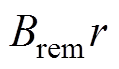
可以发现,图1中各电机等效后的拓扑均具有磁桥结构、径向结构(径向永磁体或空气区域)与切向结构(切向永磁体或空气区域),本文针对以上三种等效拓扑结构,提出一种通用解析模型,对电机的空载电磁性能进行计算,模型建立时为便于各子域及其相应边界条件的建立,做出如下简化:电机径向结构均为永磁体,其宽度为Rl-Rf;切向分布结构均为永磁体,其跨度角为a1+2a,忽略磁桥2的存在。所提出的通用解析计算模型如图2所示(后文称之为简化结构),图中,Rr为转子铁心外半径,Rs为定子铁心内半径,Rm为等效后切向结构内半径,p为电机极对数,Ⅰ、Ⅱ、Ⅲ与Ⅳ分别代表模型中的不同子域,Ax与Hxq 分别为不同子域处的矢量磁位与切向磁场强度(x=1, 2, 3, 4),各子域间边界条件将在后文给出,b 为磁桥饱和区域的跨度角[23],有
图2 所提出通用解析计算模型示意图(简化结构)
Fig.2 Schematic diagram of the proposed general model
 (7)
(7)
式中,hb1与wb1分别为磁桥1的长度与宽度。
为了验证所提等效方法的有效性,本文通过有限元对电机原始结构、等效结构及等效后简化结构(即所提出通用模型)的空载气隙磁通密度进行计算。由于V型电机结构等效后与U型电机结构相似,同时一字型电机结构又可看成V型电机结构永磁夹角为180 °时的特殊情况,故本文以具有代表性的V型电机结构为例,通过有限元对所提出的等效方法进行了验证,所计算出的不同情况下电机的空载气隙磁通密度波形对比如图3所示。可以看出,原始电机与等效后电机的空载气隙磁通密度波形吻合较好,进而证明了所提出等效方法的有效性。
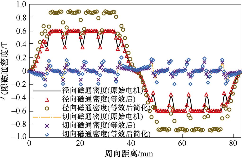
图3 不同情况下电机空载气隙磁通密度波形对比
Fig.3 Comparison of no-load air-gap flux density under different conditions
通过图3结果还可以看出,相比于原始电机气隙磁通密度波形,等效后简化结构的气隙磁通密度形状几乎未发生变化,区别仅表现在幅值的不同。气隙磁通密度形状几乎不变的原因是磁桥2的存在几乎不影响永磁体磁通进入气隙的路径,使得模型简化前后的气隙磁通具有相似的分布规律,故气隙磁通密度的形状变化较小;气隙磁通密度幅值发生变化的原因是由于模型简化后,永磁体的总量增多,使得总磁通增大,忽略磁桥2又会使漏磁减少,故使得计算出的气隙磁通密度幅值增大。U型结构电机与一字型结构电机的气隙磁通密度波形同样具有上述分布规律。
基于上述分析可知,通过对图2所示简化结构建立子域模型,求解各子域矢量磁位可得到空载气隙磁通密度分布,然后通过等效磁路法对计算结果幅值进行修正,即可得到各原始电机的空载气隙磁通密度分布,具体实现过程见下文。
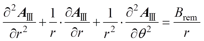
根据材料的不同特性,本文将图2中建立的模型分为四个子域:气隙(Ⅰ)、磁桥(Ⅱ)、径向永磁体(Ⅲ)与切向永磁体(Ⅳ)。考虑到模型对称性,本文假设磁极中心处为q =0,并对q ∈[0, p/2p]内的模型进行解析,其中p为电机极对数。电机各子域矢量磁位满足
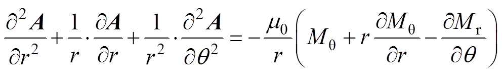 (8)
(8)
式中,A为矢量磁位;m0为真空磁导率;Mr与Mq分别为磁化强度的径向及切向分量。对于气隙子域与磁桥子域,磁化强度为零,故这两个子域满足
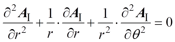 (9)
(9)
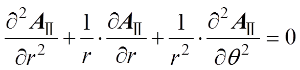 (10)
(10)
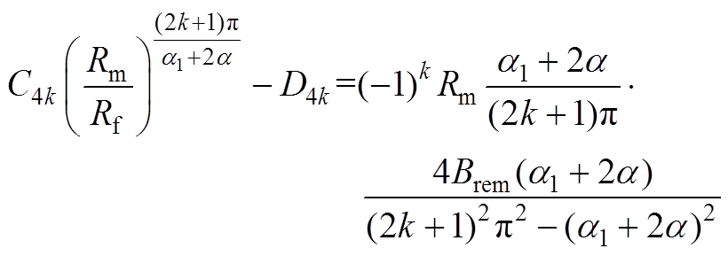
对于径向永磁体子域,以图2中S极为例,其满足Mq=-Brem/m0,¶Mq/¶r=¶Mr/¶q =0,其中Brem为永磁体剩磁;对于切向永磁体子域,其满足Mq =0,¶Mq/¶r=¶Mr/¶q=0。故对于径向与切向永磁体子域有
 (11)
(11)
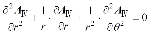 (12)
(12)
考虑到模型的周期性和对称性,各子域的矢量磁位通解[12, 23-25]可表示为
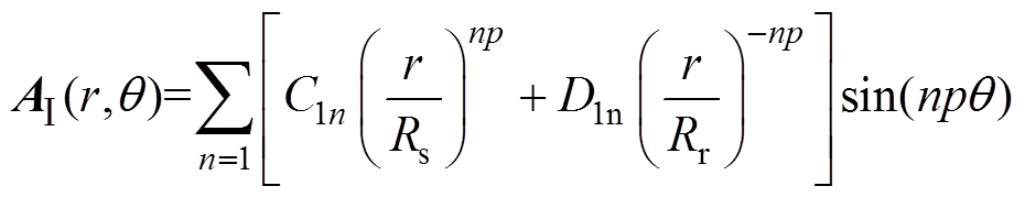 (13)
(13)
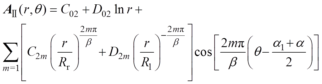 (14)
(14)
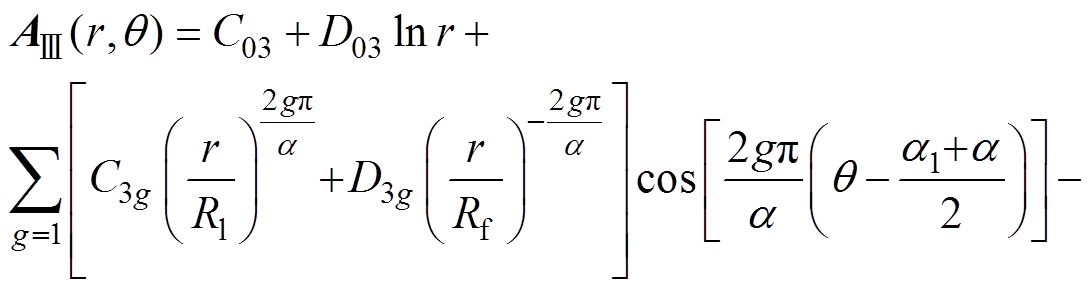
 (15)
(15)
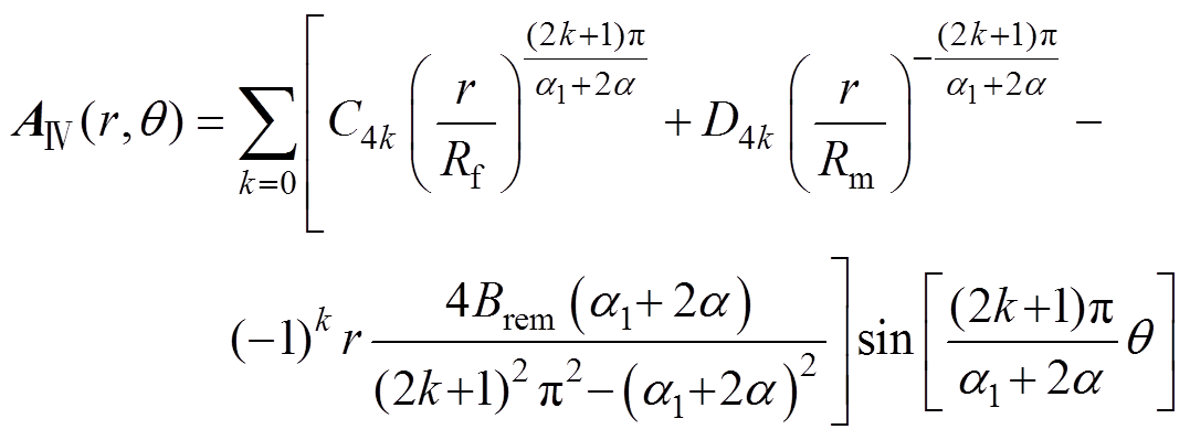 (16)
(16)
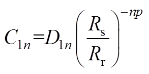
式中,n、m、g、k分别为气隙子域、磁桥子域、径向永磁体子域及切向永磁体子域的谐波次数;C1n、D1n、C02、D02、C2m、D2m、C03、D03、C3g、D3g、C4k及D4k为各子域待定系数。
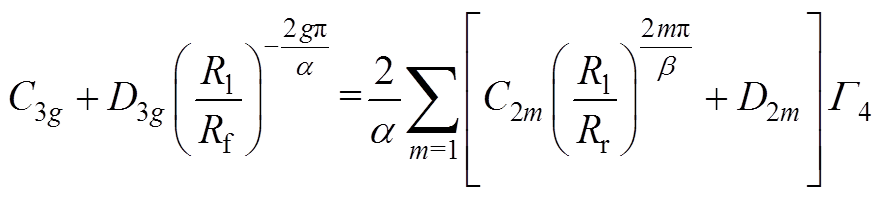
不同子域间交界面处,矢量磁位A及切向磁场强度Hq 是连续的。故在气隙子域与磁桥子域交界面处,满足如下边界条件
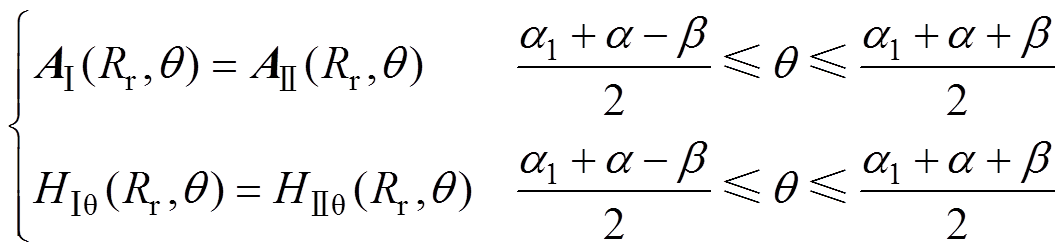 (17)
(17)
在磁桥子域与径向分布永磁体子域交界面处,满足如下边界条件
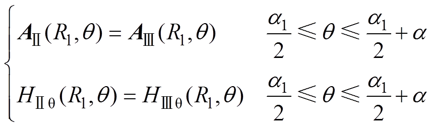 (18)
(18)
在径向分布永磁体子域与切向分布永磁体子域交界面处,满足如下边界条件
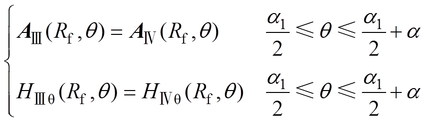 (19)
(19)
另外,由于与磁导率无穷大的铁心相邻的子域切向磁场强度为零,可得到以下边界条件
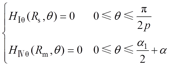 (20)
(20)
上述边界条件在模型中的位置如图2所示,由各边界条件得到的包含待定系数的方程将会在附录中给出,其中需要注意的是,方程中磁桥子域的磁导率未知,需要通过局部等效磁路法求得。
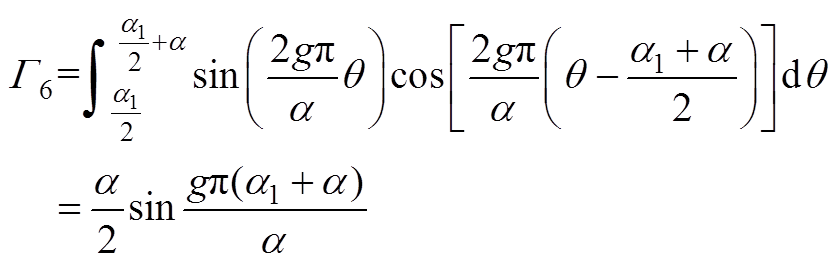
待求解的方程中磁桥磁导率应与各原始电机磁桥1处的磁导率相同,为了计算该处磁导率,建立了如图4a所示的电机通用等效磁路,图中,Gm、Gas、Gb1、Gb2、Gg分别为永磁体等效内磁导、转子空气区域磁导、磁桥1磁导、磁桥2磁导以及气隙磁导;jr为永磁体等效磁通源;jm、jas、jb1、jb2、以及jg为各支路磁通,以上磁导及各支路磁通均可根据文献[23, 30]中的公式及迭代法计算得到,进而可计算出方程中所需的磁桥磁导率。
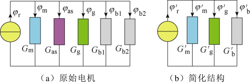
图4 原始电机及简化结构通用等效磁路
Fig.4 Equivalent magnetic circuit of different model
在求解方程组得到各子域待定系数后,可根据气隙子域矢量磁位计算出电机径向及切向气隙磁通密度表达式为
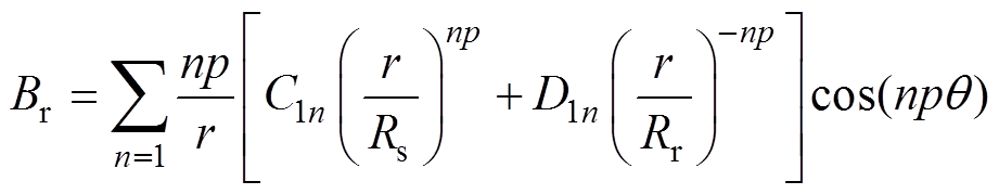 (21)
(21)
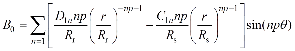 (22)
(22)
为了考虑模型简化对空载气隙磁通密度的影响,需要对式(21)、式(22)计算结果的幅值进行修正,修正后的径向及切向气隙磁通密度为
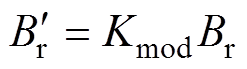 (23)
(23)
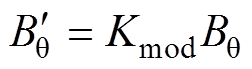 (24)
(24)
其中
 (25)
(25)
式中,Kmod为修正系数; 为图4a所示原始电机磁路中的气隙支路磁通;
 为图4b所示电机简化结构等效磁路中的气隙支路磁通,该磁路中各参数计算方法与图4a中参数计算方法相同。
本文采用保角映射的方法来考虑定子开槽对气隙磁通密度的影响。该方法的主要思想是通过几种保角变换将实际开槽的平面转换为无槽平面,然后可通过计算出的复相对气隙磁导表示开槽的影响[31]。考虑开槽后的径向及切向气隙磁通密度分别为
 (26)
(26)
 (27)
(27)
式中,la与lb分别为复相对气隙磁导的实部与虚部。
根据磁链分布可以得到电机的空载反电动势为
 (28)
(28)
其中
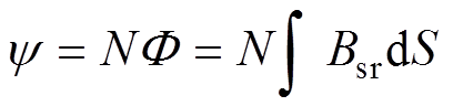 (29)
(29)
式中,y 为绕组磁链;N为每相串联匝数; 为相绕组磁通;S为相绕组区域的面积。
电机齿槽转矩可由麦克斯韦张量法计算得到
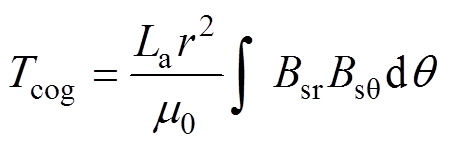 (30)
(30)
式中,La为铁心叠压长度。
结合以上分析,图5给出了本文所提通用解析模型计算流程。
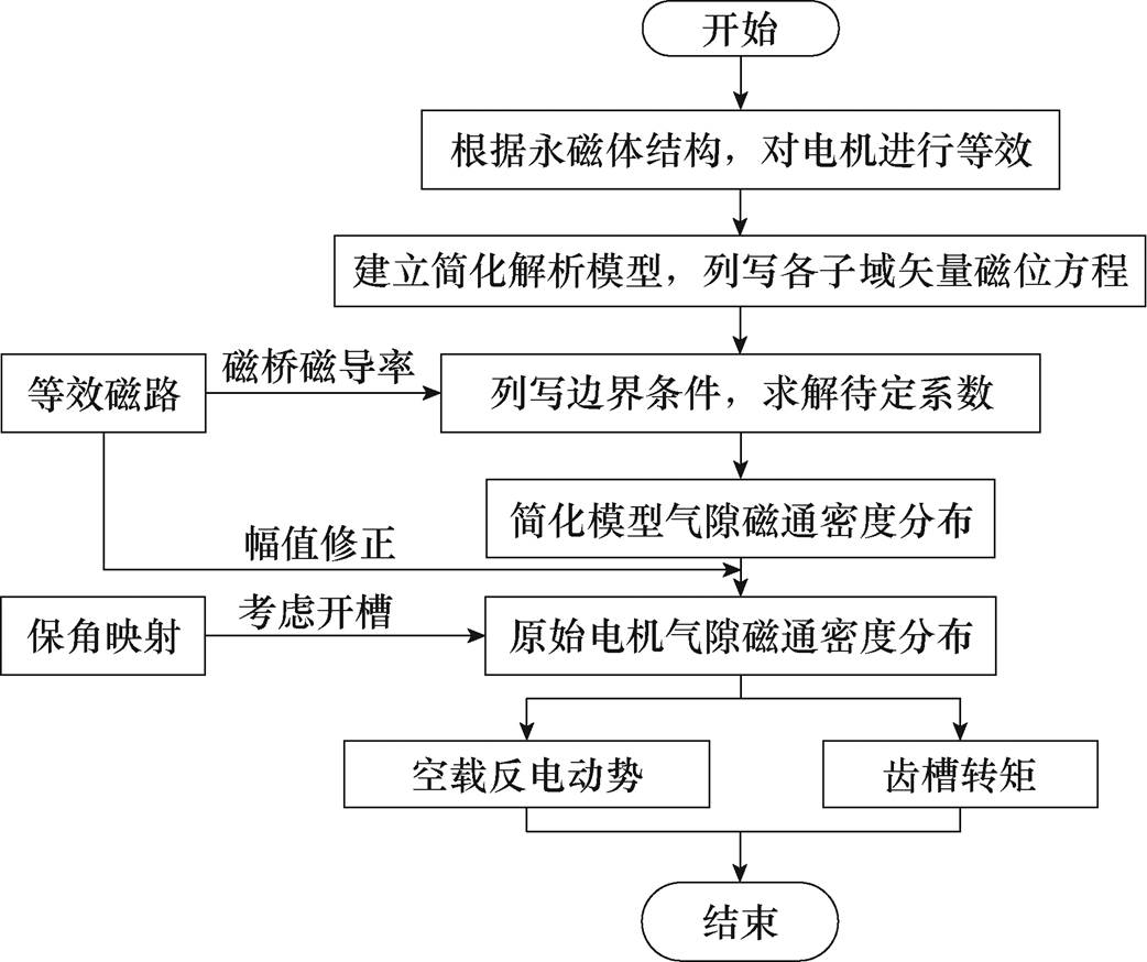
图5 内置电机空载性能解析计算流程
Fig.5 Flow chart of no-load performance analysis
为了验证所提出解析模型的有效性,本文通过解析法与有限元法分别对V型结构、U型结构与一字型结构电机的空载电磁性能进行了计算,并通过搭建实验平台对一台6极/36槽V型结构电机与一台4极/18槽一字型结构电机空载性能进行了测试。所计算电机的主要参数见表1,所测试样机图片如图6、图7所示。
表1 电机主要参数
Tab.1 Main parameters of the motors
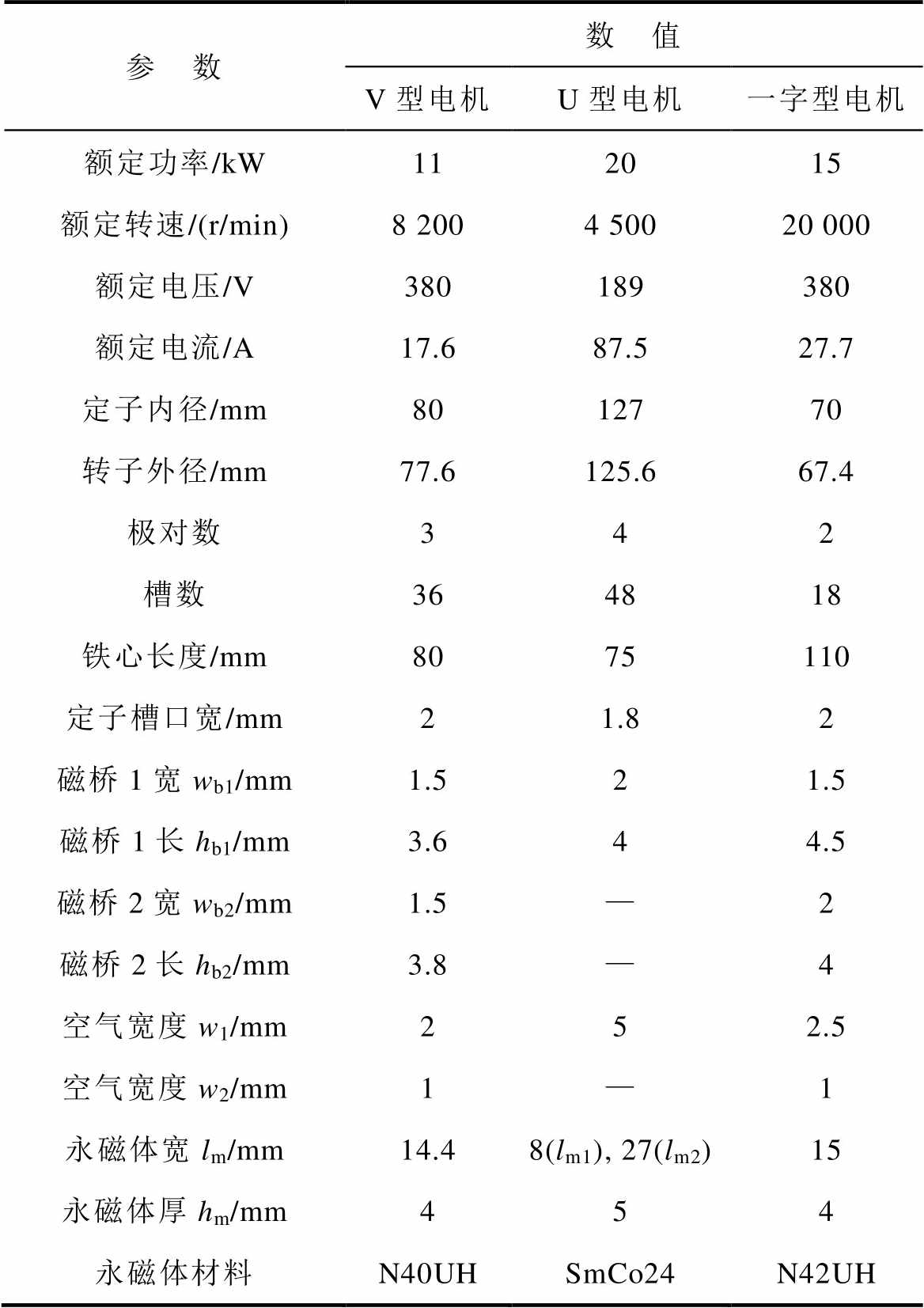
参 数数 值 V型电机U型电机一字型电机 额定功率/kW112015 额定转速/(r/min)8 2004 50020 000 额定电压/V380189380 额定电流/A17.687.527.7 定子内径/mm8012770 转子外径/mm77.6125.667.4 极对数342 槽数364818 铁心长度/mm8075110 定子槽口宽/mm21.82 磁桥1宽wb1/mm1.521.5 磁桥1长hb1/mm3.644.5 磁桥2宽wb2/mm1.5—2 磁桥2长hb2/mm3.8—4 空气宽度w1/mm252.5 空气宽度w2/mm1—1 永磁体宽lm/mm14.48(lm1), 27(lm2)15 永磁体厚hm/mm454 永磁体材料N40UHSmCo24N42UH
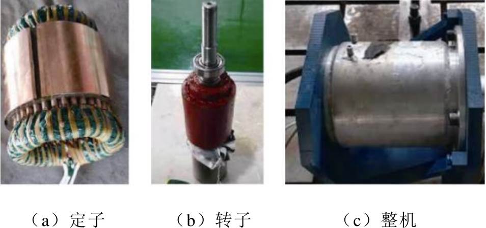
图6 V型结构样机图片
Fig.6 Prototype pictures of V-shape motor
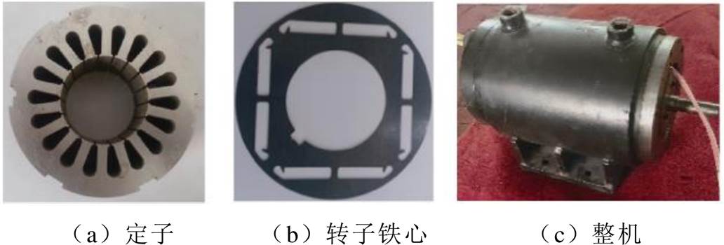
图7 一字型结构样机图片
Fig.7 Prototype pictures of straight-shape motor
通过有限元计算出的V型结构、U型结构与一字型结构电机空载磁通密度云图如图8所示。解析模型计算出的各结构电机在气隙中心处的空载气隙磁通密度分布与有限元结果对比如图9所示,可以看出,解析计算结果与有限元结果吻合良好,说明了解析模型预测空载气隙磁通密度的有效性。
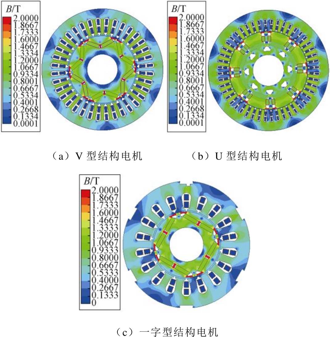
图8 电机空载磁通密度云图
Fig.8 No-load flux density cloud map of motors
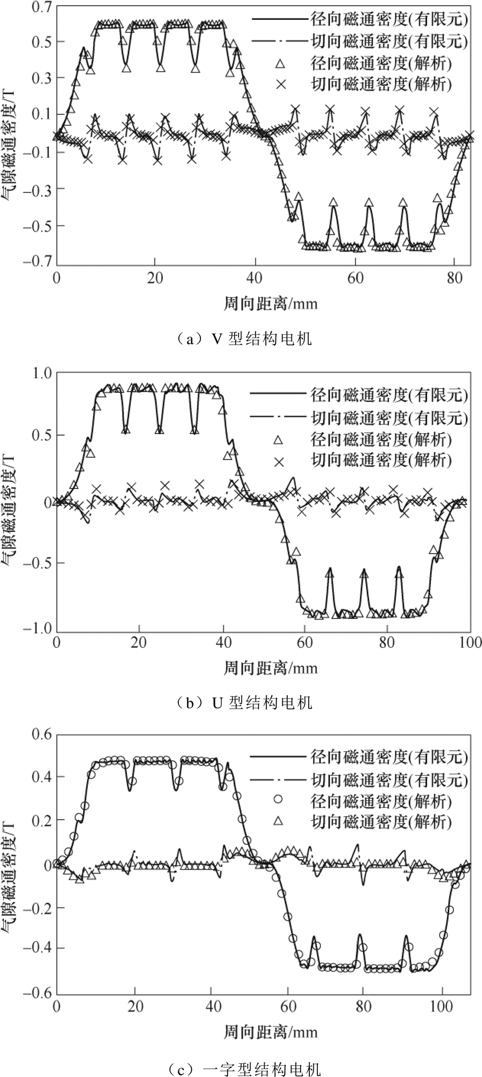
图9 空载气隙磁通密度波形对比
Fig.9 Comparison of no-load air-gap flux density
通过解析模型及有限元对V型、U型与一字型电机在转速为1 500 r/min、4 500 r/min与15 000 r/min情况下的空载线反电动势进行了计算,并将计算结果与实验结果进行了对比,如图10所示,其中还包括相应的谐波分析。可以看出,对于V型电机,有限元、解析及实验得到的反电动势基波幅值分别为85.5 V、86.2 V和84.8 V,相应的波形畸变率分别为2.57 %、1.95 %及3.02 %;对于U型电机,有限元与解析得到的反电动势基波幅值分别为213.7 V和215.9 V,相应的波形畸变率分别为4.98 %与4.7 %;对于一字型电机,有限元、解析及实验得到的反电动势基波幅值分别为318.7 V、325.3 V和320.4 V,相应的波形畸变率分别为1.09 %、1.62 %及1.55 %。可以看出,所提模型可有效计算电机空载反电动势。
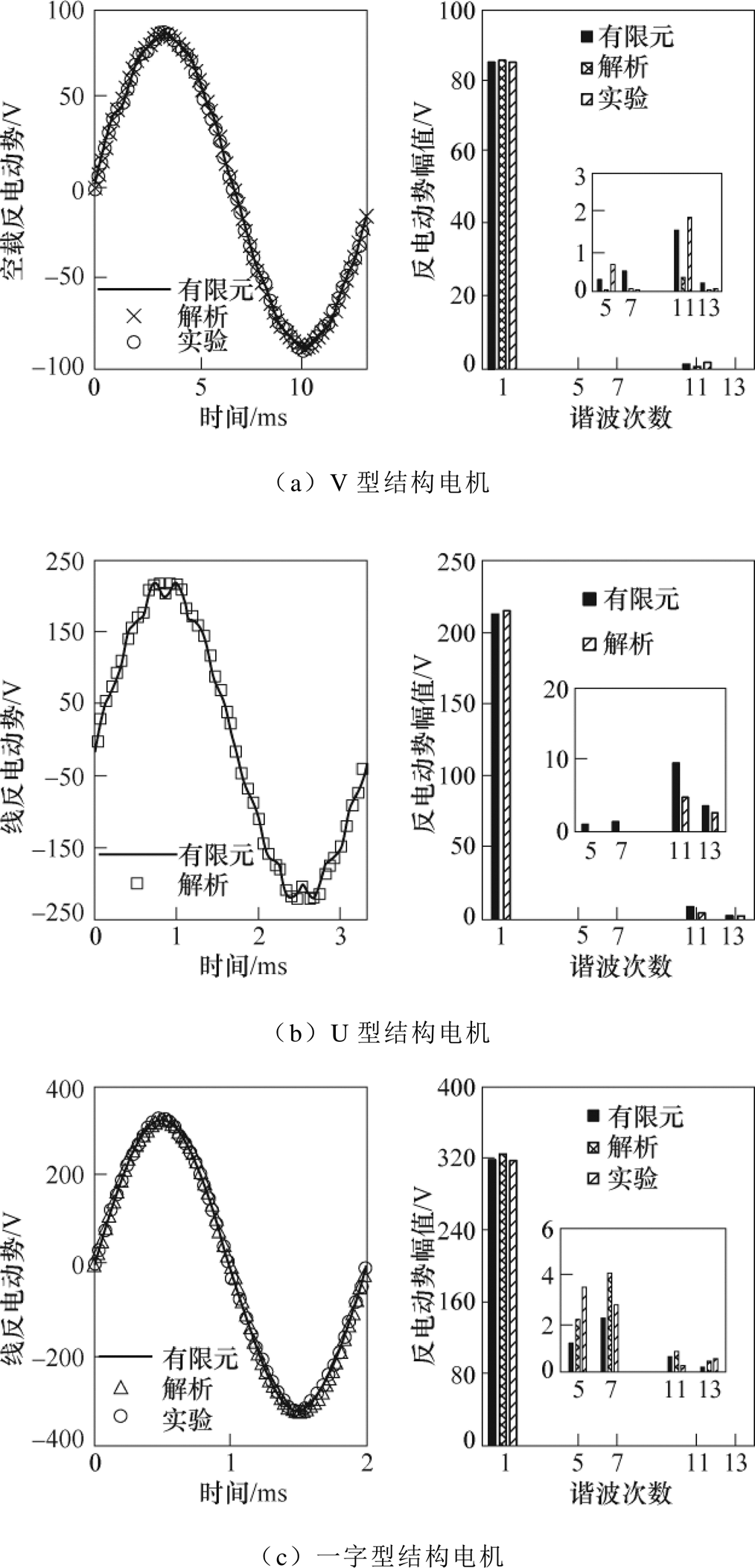
图10 空载线反电动势波形及其谐波分析
Fig.10 Back electromotive force waveforms and harmonic analysis
通过解析模型计算出了V型、U型与一字型电机在一个齿距下的齿槽转矩波形,并将其与有限元计算结果进行对比,如图11所示。可以看出,对于V型电机,有限元与解析得到的齿槽转矩幅值分别为368 mN·m与403 mN·m,计算误差为9.5 %;对于U型电机,有限元与解析得到的齿槽转矩幅值分别为609 mN·m与584 mN·m,计算误差为4.1 %;对于一字型电机,有限元与解析得到的齿槽转矩幅值分别为57 mN·m与51 mN·m,计算误差为10.5 %。可以看出,解析计算结果与有限元结果吻合良好,计算误差均在工程允许范围内。
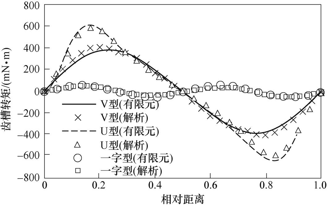
图11 齿槽转矩结果对比
Fig.11 Comparison of cogging torque
在列写附录中的方程时认为永磁体产生的磁通全部沿 方向进入磁桥1的边界,故当
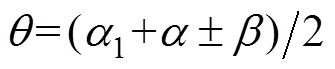 时,磁桥子域满足
 。随着磁桥饱和程度的增加,磁通不再全部沿方向进入磁桥,按照磁桥子域满足计算会产生误差。文献[29]中总结了不同磁桥饱和程度下
 的适用条件,故本文所提解析模型的适用条件与文献[29]中的 相同。
在利用有限元计算电机性能时,需要求解Nmesh×Nmesh的非线性矩阵,其中Nmesh是有限元中的节点数,这意味着有限元的计算时间主要取决于网格剖分数量。对于本文提出的解析模型,求解等效磁路以考虑磁桥饱和时仅需计算一个Nm×Nm的非线性矩阵,其中Nm为图4中等效磁路的节点数,其值远小于Nmesh;除此之外的计算时间可以忽略不计,因为附录中的方程均是线性的。故相比于有限元法,本文所提模型在计算时间上具有显著优势。
本文提出一种将子域法及等效磁路法相结合的通用解析模型,可在计及磁桥饱和的情况下,计算具有任意极槽配合的V型/U型/一字型内置式永磁电机空载电磁性能。为便于模型建立,提出了一种转子结构等效方法,这种等效为分析其他具有不规则永磁体排布结构的内置式电机提供了思路。
通过解析模型计算出的空载气隙磁通密度、线反电动势及齿槽转矩结果与有限元和实验测试结果吻合较好。解析模型计算出的线反电动势幅值及其畸变率与有限元和实验测量结果间的误差均在3 %以内;解析计算出的齿槽转矩幅值与有限元结果间的误差在10 %以内,满足工程需求。与有限元法相比,本文所提解析模型可在保证计算精度的前提下,实现V型/U型/一字型内置永磁电机空载性能的快速计算,这为相关类型电机的初始设计及优化带来了方便。
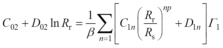
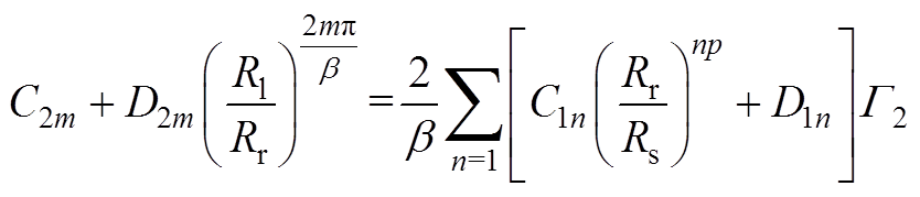
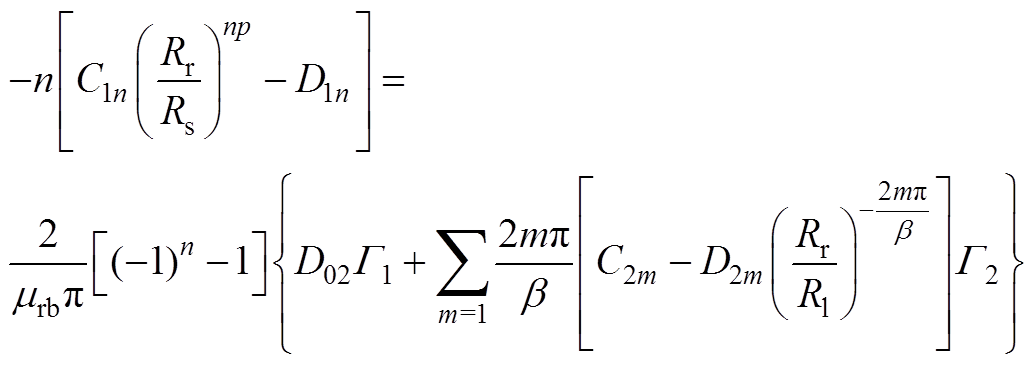
根据式(17),可得到如下方程
 (A1)
(A1)
 (A2)
(A2)
 (A3)
(A3)
式中,mrb为磁桥的相对磁导率,且
 (A4)
(A4)
当np≠2mp/b 时
 (A5)
(A5)
当np=2mp/b 时
 (A6)
(A6)
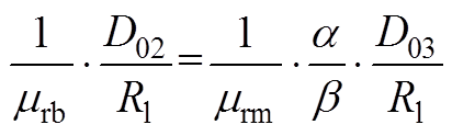
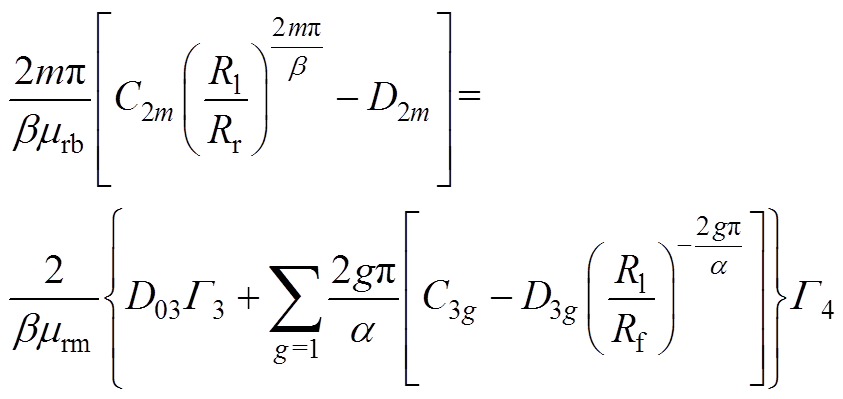
根据式(18),可得到如下方程
 (A7)
(A7)
 (A8)
(A8)
 (A9)
(A9)
 (A10)
(A10)
式中,mrm为永磁体的相对磁导率,且
 (A11)
(A11)
当am≠gb 时
 (A12)
(A12)
当am=gb 时
 (A13)
(A13)
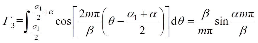
根据式(19),可得到如下方程
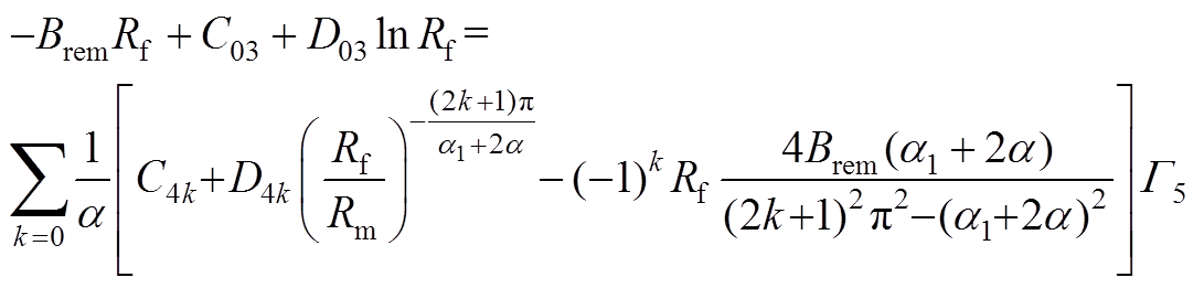 (A14)
(A14)
 (A15)
(A15)
 (A16)
(A16)
其中
 (A17)
(A17)
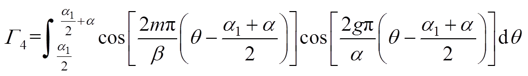
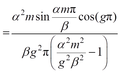
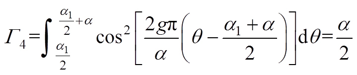
当2(a1+2a)g≠(2k+1)a 时
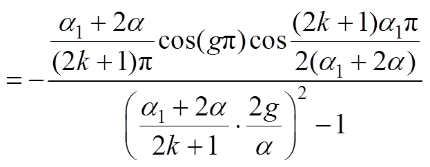 (A18)
(A18)
当2(a1+2a)g=(2k+1)a 时
 (A19)
(A19)
根据式(20),可得到如下方程
 (A20)
(A20)
 (A21)
(A21)
将式(A1)~式(A3)、式(A7)~式(A10)、(A14)~式(A16)、式(A20)、式(A21)联立方程组,通过数学软件取有限阶次,建立矩阵对系数进行求解。
参考文献
[1] 赵文祥, 刘桓, 陶涛, 等. 基于虚拟信号和高频脉振信号注入的无位置传感器内置式永磁同步电机MTPA控制[J]. 电工技术学报, 2021, 36(24): 5092- 5100.
Zhao Wengxiang, Liu Huan, Tao Tao, et al. MTPA control of sensorless IPMSM based on virtual signal and high-frequency pulsating signal injection[J]. Transactions of China Electrotechnical Society, 2021, 36(24): 5092-5100.
[2] 赵方伟, 王秀和, 赵文良, 等. 内置式永磁同步电机动态偏心故障下的轴电压解析分析和削弱[J]. 电工技术学报, 2022, 37(4): 837-848.
Zhao Fangwei, Wang Xiuhe, Zhao Wenliang, et al. Analysis and reduction of shaft voltage in interior permanent magnet synchronous motors under dynamic eccentricity fault[J]. Transactions of China Electrotechnical Society, 2022, 37(4): 837-848.
[3] 顾理成, 陈前, 赵文祥, 等. 五相永磁容错电机的相间短路容错控制[J]. 电工技术学报, 2022, 37(8): 1972-1981.
Gu Licheng, Chen Qian, Zhao Wenxiang, et al. Inter-phase short-circuit fault-tolerant control for five-phase permanent magnet fault-tolerant motors[J]. Transactions of China Electrotechnical Society, 2022, 37(8): 1972-1981.
[4] 石玉君, 程子活, 蹇林旎. 两种典型的场调制型永磁电机的对比分析[J]. 电工技术学报, 2021, 36(1): 120-130.
Shi Yujun, Cheng Zihuo, Jian Linni. Comparative analysis of two typical field modulated permanent- magnet machines[J]. Transactions of China Electro- technical Society, 2021, 36(1): 120-130.
[5] 王明杰, 贾宛英, 张志艳, 等. 永磁直线同步电机空载反电动势和推力的解析计算[J]. 电工技术学报, 2021, 36(5): 954-963.
Wang Mingjie, Jia Wanying, Zhang Zhiyan, et al. Analytical calculation of no-load eletromotive force and thrust in permanent magnet linear synchronous motors[J]. Transactions of China Electrotechnical Society, 2021, 36(5): 954-963.
[6] Liu Feng, Wang Xiuhe, Xing Zezhi, et al. Reduction of cogging torque and electromagnetic vibration based on different combination of pole arc coefficient for interior permanent magnet synchronous machine[J]. CES Transactions on Electrical Machines and Systems, 2021, 5(4): 291-300.
[7] Zhu Ziqiang, Howe D. Instantaneous magnetic field distribution in brushless permanent magnet DC motors, part I: open-circuit field[J]. IEEE Transa- ctions on Magnetics, 1993, 29(1): 124-135.
[8] Zhu Ziqiang, Howe D. Instantaneous magnetic field distribution in brushless permanent magnet DC motors, part Ⅱ: armature-reaction field[J]. IEEE Transactions on Magnetics, 1993, 29(1): 136-142.
[9] 马霁旻, 王杜, 曲荣海, 等. 基于有取向硅钢的轴向磁通开关磁阻电机准三维解析分析与设计[J]. 电工技术学报, 2018, 33(17): 4069-4077.
Ma Jimin, Wang Du, Qu Ronghai, et al. Quasi- three-dimensional analysis and design of an axial flux switched reluctance motor based on grain oriented silicon steel[J]. Transactions of China Electro- technical Society, 2018, 33(17): 4069-4077.
[10] Zhang Zhen, Xia Changliang, Wang Huimin, et al. Analytical field calculation and analysis of surface inset permanent magnet machines with high saliency ratio[J]. IEEE Transactions on Magnetics, 2016, 52(12): 1-12.
[11] Xu Lei, Zhang Chao, Zhu Xiaoyong, et al. Indirect analytical modeling and analysis of V-shaped interior PM synchronous machine[J]. IEEE Access, 2019, 7: 173786-173795.
[12] Hajdinjak M, Miljavec D. Analytical calculation of the magnetic field distribution in slotless brushless machines with U-shaped interior permanent mag- nets[J]. IEEE Transactions on Industrial Electronics, 2020, 67(8): 6721-6731.
[13] Pourahmadi-Nakhli M, Rahideh A, Mardaneh M. Analytical 2-D model of slotted brushless machines with cubic spoke-type permanent magnets[J]. IEEE Transactions on Energy Conversion, 2018, 33(1): 373-382.
[14] 赵玫, 于帅, 张华强. 聚磁式横向磁通永磁直线电机的变磁导等效磁网络[J]. 电机与控制学报, 2020, 24(4): 12-22.
Zhao Mei, Yu Shuai, Zhang Huaqiang. Variable permeability equivalent magnetic circuit network of flux-concentrated transverse flux permanent magnet linear machine[J]. Electric Machines and Control, 2020, 24(4): 12-22.
[15] He Mingjie, Li Weiye, Peng Jun, et al. Multi-layer quasi three-dimensional equivalent model of axial- flux permanent magnet synchronous machine[J]. CES Transactions on Electrical Machines and Systems, 2021, 5(1): 3-12.
[16] 陈威, 吴桂初, 方攸同. 基于绕组分布函数理论和动态磁网络的两种内置式永磁牵引电机解析建模方法[J]. 电工技术学报, 2020, 35(增刊2): 377-386.
Chen Wei, Wu Guichu, Fang Youtong. Two analytical models based on winding function theory and dynamic reluctance mesh for interior permanent magnet traction machines[J]. Transactions of China Electrotechnical Society, 2020, 35(S2): 377-386.
[17] Ding Ling, Liu Guohai, Chen Qian, et al. A novel mesh-based equivalent magnetic network for perfor- mance analysis and optimal design of permanent magnet machines[J]. IEEE Transactions on Energy Conversion, 2019, 34(3): 1337-1346.
[18] Liu Guohai, Wang Yong, Chen Qian, et al. Design and analysis of a new equivalent magnetic network model for IPM machines[J]. IEEE Transactions on Magnetics, 2020, 56(6): 1-12.
[19] Wu Shuang, Shi Tingna, Guo Liyan, et al. Accurate analytical method for magnetic field calculation of interior PM motors[J]. IEEE Transactions on Energy Conversion, 2021, 36(1): 325-337.
[20] Li Zhaokai, Huang Xiaoyan, Wu Lijian, et al. An improved hybrid field model for calculating on-load performance of interior permanent-magnet motors[J]. IEEE Transactions on Industrial Electronics, 2021, 68(10): 9207-9217.
[21] Wu Shuang, Guo Liyan, Wang Huimin, et al. Indu- ctance calculation of interior permanent magnet machines considering asymmetrical saturation of the bridge[J]. IEEE Transactions on Magnetics, 2019, 55(11): 1-11.
[22] Farshadnia M, Cheema M A M, Dutta R, et al. Analytical modeling of armature reaction air-gap flux density considering the non-homogeneously saturated rotor in a fractional-slot concentrated-wound IPM machine[J]. IEEE Transactions on Magnetics, 2016, 53(2): 1-12.
[23] Liang Peixin, Chai Feng, Bi Yunlong, et al. Analyti- cal model and design of spoke-type permanent- magnet machines accounting for saturation and nonlinearity of magnetic bridges[J]. Journal of Magnetism and Magnetic Materials, 2016, 417: 389-396.
[24] Liang Peixin, Chai Feng, Li Yi, et al. Analytical prediction of magnetic field distribution in spoke-type permanent-magnet synchronous machines accounting for bridge saturation and magnet shape[J]. IEEE Transactions on Industrial Electronics, 2017, 64(5): 3479-3488.
[25] Liang Peixin, Chai Feng, Chen Lei, et al. Analytical prediction of no-load stator iron losses in spoke-type permanent-magnet synchronous machines[J]. IEEE Transactions on Energy Conversion, 2018, 33(1): 252-259.
[26] Zhang Zhen, Xia Changliang, Yan Yan, et al. A hybrid analytical model for open-circuit field calculation of multilayer interior permanent magnet machines[J]. Journal of Magnetism and Magnetic Materials, 2017, 435: 136-145.
[27] An Yuansheng, Ma Conggan, Zhang N, et al. Open- circuit air-gap magnetic field calculation of interior permanent magnet synchronous motor with V-shaped segmented skewed poles using hybrid analytical method[J]. IEEE Transactions on Magnetics, 2021, 57(12): 1-9.
[28] Faradonbeh V Z, Rahideh A, Boroujeni S T, et al. 2-D analytical no-load electromagnetic model for slotted interior permanent magnet synchronous machines[J]. IEEE Transactions on Energy Conversion, 2021, 36(4): 3118-3126.
[29] Li Shiqi, Tong Wenming, Hou Mingjun, et al. Analytical model for no-load electromagnetic perfor- mance prediction of V-shape IPM motors considering nonlinearity of magnetic bridges[J]. IEEE Transa- ctions on Energy Conversion, 2022, 37(2): 901-911.
[30] Lim D K, Yi K P, Woo D K, et al. Analysis and design of a multi-layered and multi-segmented interior permanent magnet motor by using an analytic method[J]. IEEE Transactions on Magnetics, 2014, 50(6): 1-8.
[31] Zarko D, Ban D, Lipo T A. Analytical calculation of magnetic field distribution in the slotted air gap of a surface permanent-magnet motor using complex relative air-gap permeance[J]. IEEE Transactions on Magnetics, 2006, 42(7): 1828-1837.
Abstract Interior permanent magnet (IPM) motors, due to the high power/torque density and wide speed range, are widely used in industrial applications and smart homes. Considerable computation time is one of the major issues faced by designers due to the changeable rotor configurations. The finite element analysis (FEA) is widely used in motor design due to its ability to consider saturation and complex geometries. However, the need for high-precision mesh is time-consuming. The analytical method has acceptable accuracy and fast calculation, which is regarded as an effective tool by designers. However, the existing analytical models are not universal. Therefore, this paper proposes a novel general analytical model to predict the no-load performance of IPM motors with different topologies.
Firstly, the magnets with different topologies are equivalent according to the principle that the total flux produced by the magnets is constant, facilitating the establishment of subdomains. Secondly, based on the boundary conditions between different subdomains, the field governing equations can be obtained to solve the undetermined coefficients. Thirdly, the magnetic equivalent circuit (MEC) method is employed to obtain the permeability of magnetic bridges to consider the effect of saturation and improve the calculation accuracy. Finally, the influence of slotting is considered based on the conformal mapping method to obtain the air-gap magnetic field of slotted motors. The proposed general model is suitable for V-shape, U-shape, and straight-shape IPM motors with any slot-pole combination. The computation time is greatly shortened compared with FEA because the equations to be solved are linear.
The calculated no-load air-gap flux density waveforms, back electromotive force (EMF), and cogging torque by the proposed model are in good agreement with those of FEA results. For the V-shape motor, the fundamental amplitudes of back EMF obtained by FEA, analytical model and experiment are 85.5 V, 86.2 V, and 84.8 V, respectively; the corresponding total harmonic distortions (THDs) are 2.57 %, 1.95 %, and 3.02 %, respectively. For the U-shape motor, the fundamental amplitudes of back EMF obtained by FEA and analytical model are 213.7 V and 215.9 V, respectively; the THDs are 4.98 % and 4.7 %, respectively. For the straight-shape motor, the fundamental amplitudes of back EMF obtained by FEA, analytical model and experiment are 318.7 V, 325.3 V, and 320.4 V, respectively; the THDs are 1.09 %, 1.62 %, and 1.55 %, respectively. The amplitudes of cogging torque for the V-shape motor calculated by FEA and analytical model are 368 mN·m and 403 mN·m, the calculation error is 9.5 %. The amplitudes of cogging torque for the U-shape motor are 609 mN·m and 584 mN·m, and the calculation error is 4.1 %. The amplitudes of cogging torque for the straight-shape motor are 57 mN·m and 51 mN·m, the calculation error is 10.5 %. The above results show that the model can effectively calculate the no-load performance of IPM motors with different rotor structures.
The following conclusions can be drawn from the above analysis: (1) Compared with FEA, the proposed general model can significantly reduce the computational cost since the calculation is based on linear equations rather than numerical iteration. (2) The proposed model has higher precision, and the errors between calculated and FEA results are within the allowable range of the engineering. (3) The proposed magnet equivalence method provides ideas for the analytical derivation of other types of IPM motors with irregular magnets arrangement, which brings convenience to the design and optimization of related types of motors.
keywords:Interior permanent magnet synchronous motors, subdomain method, magnetic equivalent circuit, magnetic bridge saturation
DOI: 10.19595/j.cnki.1000-6753.tces.220486
中图分类号:TM351
辽宁省“兴辽英才计划”(XLYC2007107)和辽宁省百千万人才工程资助项目。
收稿日期 2022-04-02
改稿日期 2022-05-12
李世奇 男,1998年生,博士研究生,研究方向为非晶合金高速永磁电机设计及多物理场分析。E-mail: 18840659110@163.com
佟文明 男,1984年生,教授,博士生导师,研究方向为特种电机及其控制与电机多物理场仿真分析。E-mail: twm822@126.com(通信作者)
(编辑 崔文静)