 可用DFIG转子转速变化量和固有转动惯量表示[21]为
摘要 随着具备惯量调节能力的双馈风力发电机组大规模接入电网,电网的功角稳定特性变得更加复杂。该文以双馈风机(DFIG)接入两区域互联电网为研究背景,首先推导两区域惯性中心等效模型,分析DFIG直接接入电网时虚拟惯量对两区域惯性中心转子运动方程的影响;然后从系统暂态能量的角度出发,研究系统发生三相短路故障及负荷突增时,系统功角摆动方向不同、两区域互联系统DFIG等效惯量控制环节比例系数不同对系统加速及减速过程中暂态能量的影响,进而研究其对系统功角首摆稳定的影响机理;最后通过系统功角首摆最大偏移量对系统功角首摆稳定性进行评估,并在PSASP仿真软件中搭建两区域系统仿真模型,验证所提理论的正确性。
关键词:双馈风机 等效惯量控制比例系数 暂态能量函数 系统功角首摆稳定
与传统同步机相比,双馈风力发电机(Doubly-Fed Induction Generator, DFIG)缺乏惯性响应能力[1-2],因此,大规模双馈风机接入后的电力系统遭受大扰动或小扰动时(三相短路、负荷突增等),系统惯性响应能力缺失严重,暂态功角稳定问题突显。随着双馈风机虚拟惯量控制技术不断完善,双馈风机能够为系统提供动态惯性支撑[3-5],因此,亟须开展双馈风机虚拟惯量对系统功角首摆稳定影响机理的研究。
当前,国内外学者研究双馈风机惯量控制比例系数对系统功角稳定性的影响时,主要考虑送/受端区域内DFIG分别附加虚拟惯量控制[6-10],但对送受端区域内DFIG同时附加惯量控制缺乏考虑,较少关注两区域互联系统DFIG虚拟惯量控制环节比例系数对系统功角稳定的影响机理。文献[7]对送端/受端分别附加虚拟惯性对系统暂态稳定的影响进行研究,提出系统受到扰动后,若功角首摆为正、增加受电区域内风电机组的虚拟惯量时,系统功角稳定性降低;增加送电区域内风电机组的虚拟惯量时,系统暂态稳定水平取决于减速能量的减小幅度。功角反向摆动时,风电场虚拟惯量的控制效果与功角正摆时相反。文献[8]研究送端/受端区域内DFIG接入对系统相对转速加速度的偏差函数的影响,提出两区域间相对转速加速度的变化趋势主要由并网DFIG和新增负荷的暂态功率响应的差值决定,也受到系统故障期间并网DFIG与新增负荷端电压跌落幅度的影响。文献[9]研究两机系统中送/受端系统惯性时间常数变化对系统功角暂态稳定性的影响,提出当送端机组出力小于受端机组出力,且两端机组出力相差较大时,受端系统惯性时间常数增大,系统暂态稳定水平提高;当两端机组出力相差不大,或送端机组出力大于受端机组出力时,受端系统惯性时间常数增大,系统暂态稳定水平下降。在两机系统中,相同的运行方式下,受端系统惯性时间常数增大和送端系统惯性时间常数增大对电网暂态稳定水平的影响大致相反。文献[10]研究不同运行方式、不同故障位置、火电与风电不同配比条件对高渗透率风电的送端电网系统暂态稳定性的影响。
有学者提出“区域惯性中心等效理论”分析互联系统功角首摆稳定的内在机理,将系统中具有紧密电气联系和相似的暂态功角行为特征的同步发电机组划分为同一区域。通过推导各区域惯性中心转子运动方程,研究区域互联系统功角首摆稳定的内在机理[11],在多机系统的暂态稳定分析中具有重要意义。薛禹胜院士提出从暂态能量的角度分析系统遭受大干扰和小干扰后功角首摆稳定内在机理[12]。文献[13]基于DFIG的大容量风电机组接入单机无穷大系统模型,推导出含风机的网络暂态能量函数,分析含有大容量风电的系统暂态稳定性。文献[14-16]将两区域互联系统等值为单机无穷大系统模型,进而分析大规模风电接入后系统功角暂态稳定性。
现有文献大多基于扩展等面积定则推导系统极限切除角和极限切除时间,进而分析系统功角稳定内在机理,较少关注在第一个振荡周期内系统功角变化规律及内在机理。文献[17-20]将含DFIG的两机系统等值为含DFIG的单机无穷大系统,运用等面积法则分析风机接入位置、容量等对系统极限切除角、极限切除时间进行理论计算,而未关注系统功角首摆稳定的内在机理。
因此,本文以DFIG接入两区域电网为研究背景,首先建立两区域惯性中心等效模型,分析DFIG虚拟惯量对两区域惯性中心同步机转子运动方程的影响;然后从暂态能量函数的角度出发,分析系统发生三相短路故障及负荷突增时,系统功角摆动方向不同、两区域互联系统DFIG等效惯量控制比例系数不同,对系统加速及减速过程中暂态能量的影响,进而研究对系统功角首摆稳定性的影响机理;最后提出系统功角首摆最大偏移对系统功角稳定性进行评估,并在PSASP中搭建两区域互联系统仿真模型对上述理论进行仿真验证。
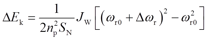
DFIG惯性响应过程中的动能变化量可用DFIG转子转速变化量和固有转动惯量表示[21]为
 (1)
(1)
式中,np为DFIG定子绕组极对数;SN为额定容量;JW为固有转动惯量;ωr0为初始转子角速度;Δωr为转子角速度增量。
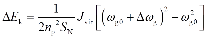
DFIG经典虚拟惯量控制模型如图1所示,由于惯性响应过程中DFIG转速与系统角速度耦合,DFIG动能变化量可表示[21]为
 (2)
(2)
式中,Jvir为DFIG等效转动惯量;ωg0为系统初始同步角速度;Δωg为系统同步角速度增量。
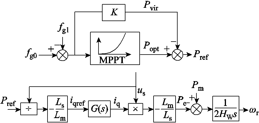
图1 DFIG经典虚拟惯量控制模型
Fig.1 Classic virtual inertia control model of DFIG
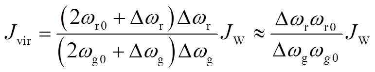
由式(1)和式(2)可知,DFIG等效转动惯量可表示为
 (3)
(3)
DFIG等效惯性时间常数定义为额定转速下存储的动能与额定容量的比值[21],即
 (4)
(4)
式中,ωN为风电机组额定角速度;HW为DFIG固有惯性时间常数,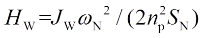 。
。
DFIG虚拟惯量响应过程中,由于电流内环响应速度远大于发电机机电暂态过程,因此将电流内环等效为一阶惯性环节。定子磁链的变化忽略不计[22],近似认为保持不变,DFIG电磁功率参考值变化量ΔPref由最大功率跟踪控制提供的ΔPopt和惯量控制提供的ΔPvir决定,即
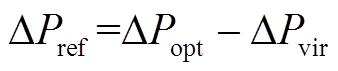 (5)
(5)
假设DFIG转速从ωr0变化到ωr1,转速变化较小,ΔPopt、ΔPvir可表示为[22]
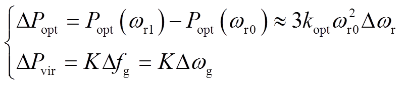 (6)
(6)
式中,kopt为最大功率跟踪曲线的比例系数;K为惯量控制比例系数。
ΔPref、ΔPe可表示为
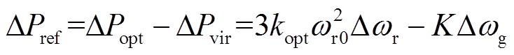 (7)
(7)
 (8)
(8)
式中,τ为变流器时间常数,τ取0.02s。
当DFIG转速变化时,DFIG转子运动方程为
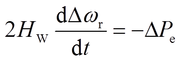 (9)
(9)
将式(8)代入式(9)可得
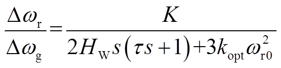 (10)
(10)
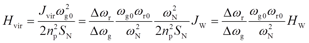
将式(10)代入式(4)可得DFIG等效惯性时间常数频域表达式为
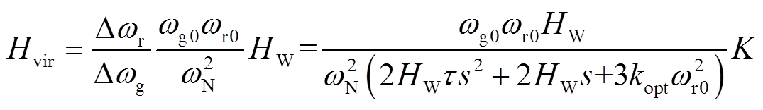 (11)
(11)
若令
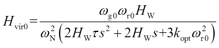 (12)
(12)
Hvir可进一步表示为
 (13)
(13)
式中,Hvir0表征惯量响应过程中DFIG等效惯性时间常数Hvir变化趋势;K表征DFIG等效惯性时间常数Hvir大小。
由式(13)可知,若风电场内DFIG具有相同基本参数,DFIG惯量响应过程中等效惯性时间常数Hvir0在时域内具有相同的变化趋势,首先迅速达到最大值,随后开始下降,最终趋于稳定[22]。
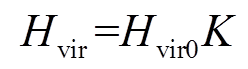
假设遭受大扰动或小扰动后系统的失稳模式为两机模式,根据联络线功率传输方向将系统两侧同步机分为送端机群及受端机群,G1为送端机群(S机群),G2为受端机群(R机群)[23],DFIG直接接入送受端机群的并网母线,两机系统等效模型如图2所示。
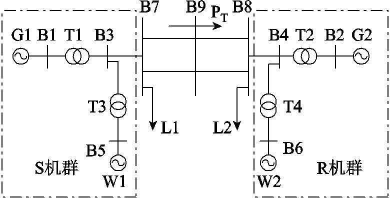
图2 两区域互联系统等效模型
Fig.2 Simplified model of two-area interconnected system
由“区域惯性中心等效理论”可知,区域惯性中心的惯性时间常数可表示为![]() ,其中
,其中 为区域内同步机惯性时间常数。区别于传统同步发电机转动惯量,DFIG虚拟惯量通过改变风机输出有功功率实现惯量响应。因此DFIG直接接入送/受端机群时,不改变接入区域总惯量,但区域内同步发电机的机械功率和电磁功率相应减少。根据区域惯性中心惯性时间常数的定义及DFIG实现惯量响应的物理本质可知,DFIG接入后区域惯性中心惯性时间常数、机械功率及电磁功率可表示为[8]
 (14)
(14)
式中,H、 分别为DFIG接入前、后区域惯性中心等效惯性时间常数;Pm、
 分别为DFIG接入前、后区域惯性中心等值机械功率;
 、Pe分别为DFIG接入前、后区域惯性中心等值电磁功率;Pmw、Pew分别为DFIG机械功率和电磁功率。
由DFIG转子运动方程可知,DFIG机械功率及电磁功率可表示为
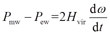 (15)
(15)
式中,ω为DFIG所在区域内同步发电机转速。
假设S机群同步机功角超前于R机群,系统两侧同步机转子运动方程表达式修正为[24]
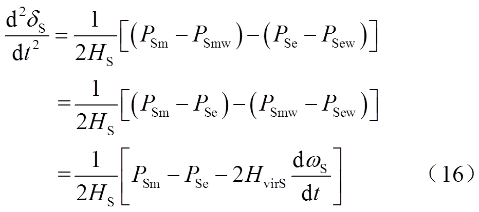
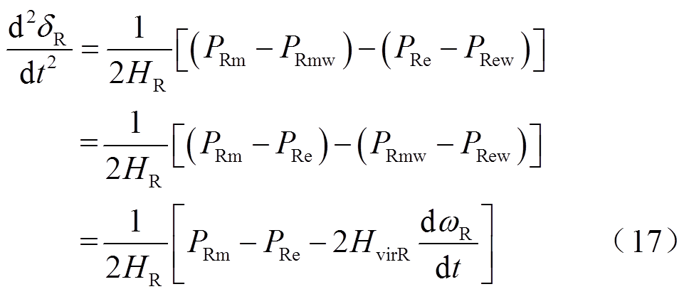
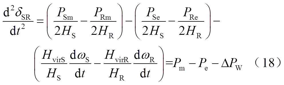
式中,δS、δR分别为S机群、R机群等效功角;δSR为系统功角,δSR=δS-δR;PSm、PRm、PSe、PRe分别为DFIG接入前S机群、R机群同步机等值机械功率和电磁功率;PSmw、PRmw、PSew、PRew分别为S机群、R机群内DFIG的机械功率和电磁功率;HS、HR分别为S机群、R机群同步机惯性时间常数;HvirS、HvirR分别为S机群、R机群DFIG等效惯性时间常数;ωS、ωR分别为S机群、R机群同步机转速; DPW为DFIG接入引起的系统等值功率变化量。
系统遭受扰动后,两端功角差将出现摆动。当 时,系统功角正向摆动,如图3所示;当
 时,系统功角反向摆动,如图4所示。
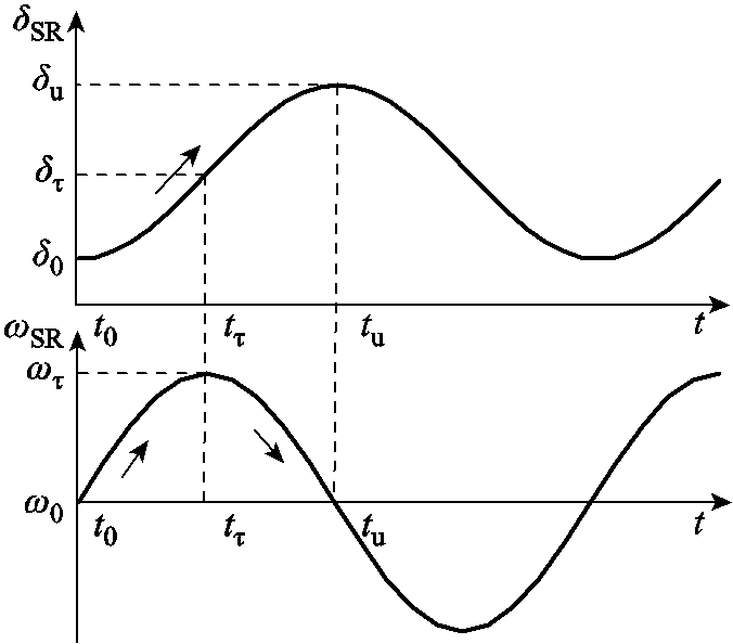
图3 系统功角正向摆动
Fig.3 Swing forward of system power angle
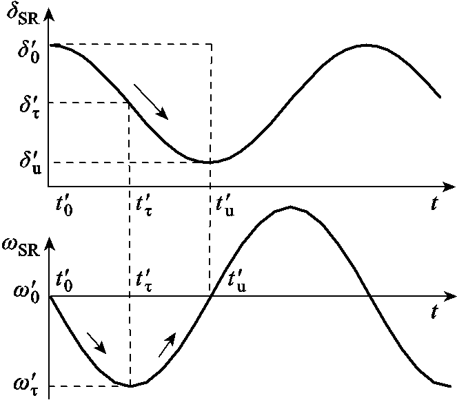
图4 系统功角反向摆动
Fig.4 Swing backward of system power angle
功角正向摆动时,系统暂态能量VT可表示为
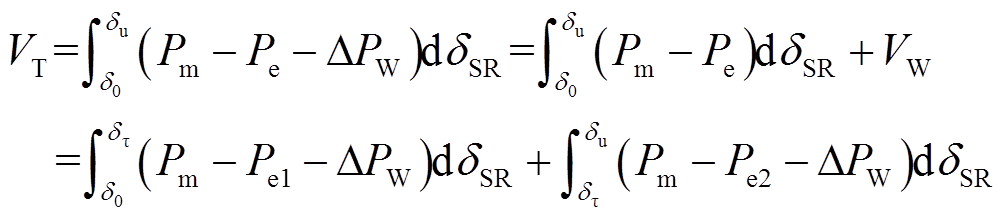 (19)
(19)
式中,Pe1、Pe2分别为系统加速及减速期间等值电磁功率;VW为DFIG提供的暂态能量,可表示为
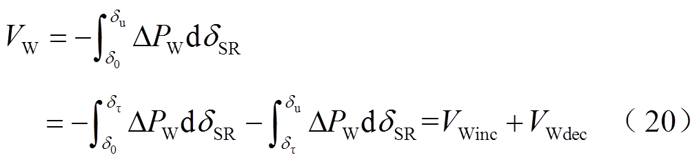
式中,VWinc和VWdec分别为系统加速及减速过程中DFIG提供的暂态能量。
系统暂态能量 可表示为
可表示为
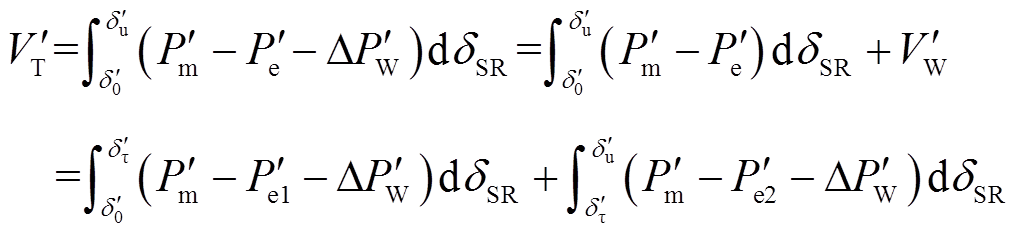 (21)
(21)
式中,、分别为系统功角反向摆动时,系统等值机械功率、电磁功率; 为系统功角反向摆动时DFIG接入引起的系统等值功率变化量;
 为系统功角反向摆动时DFIG提供的暂态能量;
 、
、 分别为系统功角反向摆动时系统加速及减速期间等值电磁功率。
式(21)中DFIG提供的暂态能量可表示为
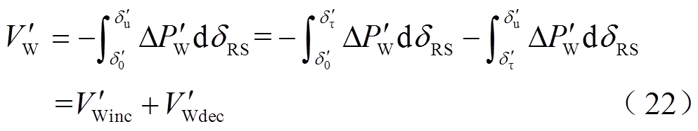
式中, 和
和 分别为系统功角反向摆动时,系统加速及减速过程中DFIG提供的暂态能量。
基于能量观点的功角稳定性统一分析理论[23],当系统遭受大干扰或小干扰时(以下统称“扰动”),系统暂态能量VT表示为
 (23)
(23)
式中,Ainc、Adec分别为系统功角首摆期间系统加速及减速面积。
在系统加速/减速阶段,若DFIG虚拟惯量使得加速面积减小/减速面积增加,暂态能量VW、、VT、 减小,将有利于系统功角首摆稳定性。通过分析DFIG虚拟惯量对系统暂态能量的影响,将进一步明确其对系统功角首摆稳定的影响。
系统发生功角振荡时,S机群与R机群同步机转子转速振幅比等于惯性时间常数的倒数,即 [25],因此系统加速过程中DFIG提供的暂态能量VWinc可表示为
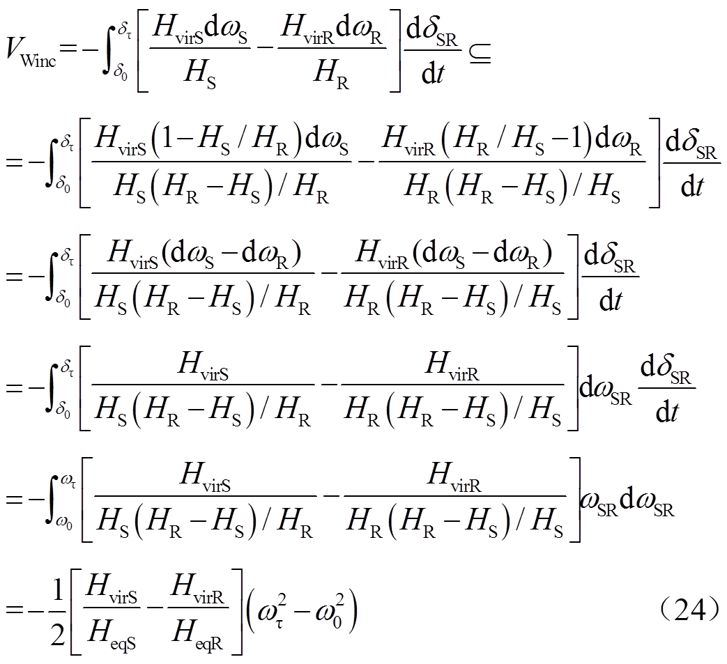
式中,HeqR=HR(HR-HS)/HS;HeqS=HS(HR-HS)/HR;![]() ;
;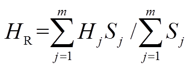 ;Si、Hi、Sj、Hj分别为S机群第i台发电机及R机群内第j台同步发电机的额定功率及惯性时间常数;m、n分别为S机群及R机群内同步发电机台数。由于实际系统中两区域内同步发电机容量、台数及惯性时间常数一般不完全相同,因此本文忽略HS、HR取值相同的情况。
由式(13)可知,加速过程中DFIG提供的暂态能量VWinc 进一步化简为
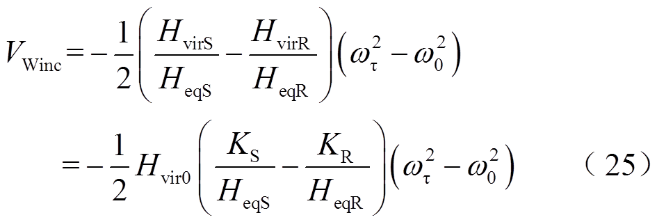
式中, 为DFIG等效惯量控制比例系数。
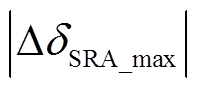
功角正向/反向摆动时,系统加速过程中,系统转速ωSR从ω0加速到ωτ,由式(25)可知,若 ,
, ,系统暂态能量VT减小,系统功角首摆稳定性增强,若调节KS及KR使得
 增大,系统暂态能量VT将继续减小,系统功角首摆稳定性将进一步增强;反之,系统功角首摆稳定性将减弱。
DFIG在系统减速过程中提供的暂态能量VWdec可表示为
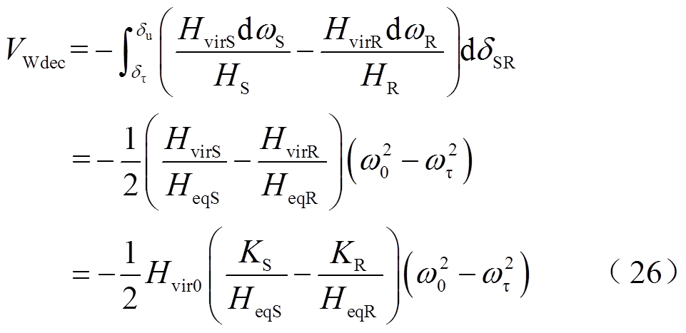
功角正向/反向摆动时,系统减速过程中,系统转速ωSR从ωτ减速到ω0,由式(26)可知,若 ,
, ,系统暂态能量VT增加,系统功角首摆稳定性减弱,若调节KS及KR使得增大,暂态能量VT将继续增大,系统功角首摆稳定性将进一步减弱;反之,系统功角首摆稳定性将增强。
系统功角正向及反向摆动时,系统加速及减速阶段系统功角首摆稳定性判别方式见表1、表2。
表1 系统功角正向摆动时功角首摆稳定性判别
Tab.1 The stability criterion of the first swing of power angle
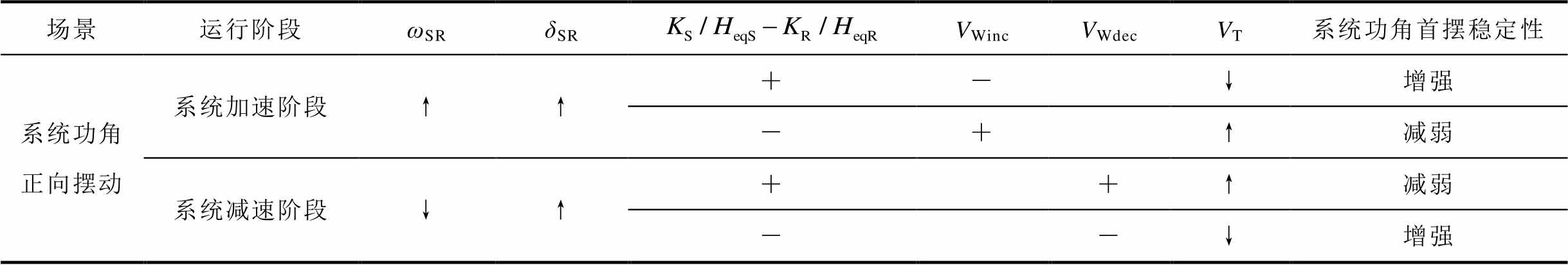
场景运行阶段ωSRδSRVWincVWdecVT系统功角首摆稳定性 系统功角正向摆动系统加速阶段↑↑+-↓增强 -+↑减弱 系统减速阶段↓↑++↑减弱 --↓增强
表2 系统功角反向摆动时功角首摆稳定性判别
Tab.2 The stability criterion of the first swing of power angle
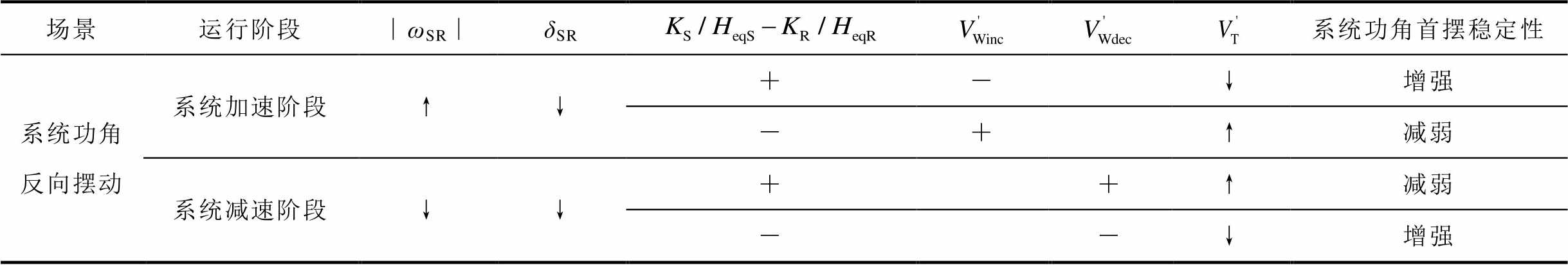
场景运行阶段∣ωSR∣δSR系统功角首摆稳定性 系统功角反向摆动系统加速阶段↑↓+-↓增强 -+↑减弱 系统减速阶段↓↓++↑减弱 --↓增强
PSASP采用DFIG经典虚拟惯量控制方法进行建模,引入电网频率偏差信号,改变DFIG有功功率和转子转速,为电网提供动态有功功率支撑。在PSASP软件搭建两区域互联系统,风电场由单台DFIG等值表示,分别从母线B3、B4并网,如图1所示。系统两侧同步发电机惯性时间常数 ,
, ,
, ,
, ,风电机组与同步发电机相关参数见表3、表4,其中含有“′”“″”的参数分别为暂态和次暂态变量。
为评估不同场景下系统功角首摆稳定性,采用系统功角首摆最大偏移量的绝对值|ΔδSR_max|作为系统功角稳定评估的指标。当|ΔδSR_max|减小时,系统功角首摆稳定性增强;反之,系统功角首摆稳定性减弱。
表3 单台风电机组参数
Tab.3 Parameters of DFIG
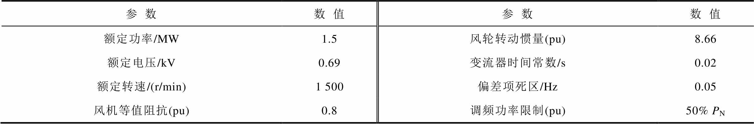
参数数值参数数值 额定功率/MW1.5风轮转动惯量(pu)8.66 额定电压/kV0.69变流器时间常数/s0.02 额定转速/(r/min)1 500偏差项死区/Hz0.05 风机等值阻抗(pu)0.8调频功率限制(pu)50% PN
表4 单台同步机参数
Tab.4 Parameters of synchronous generators
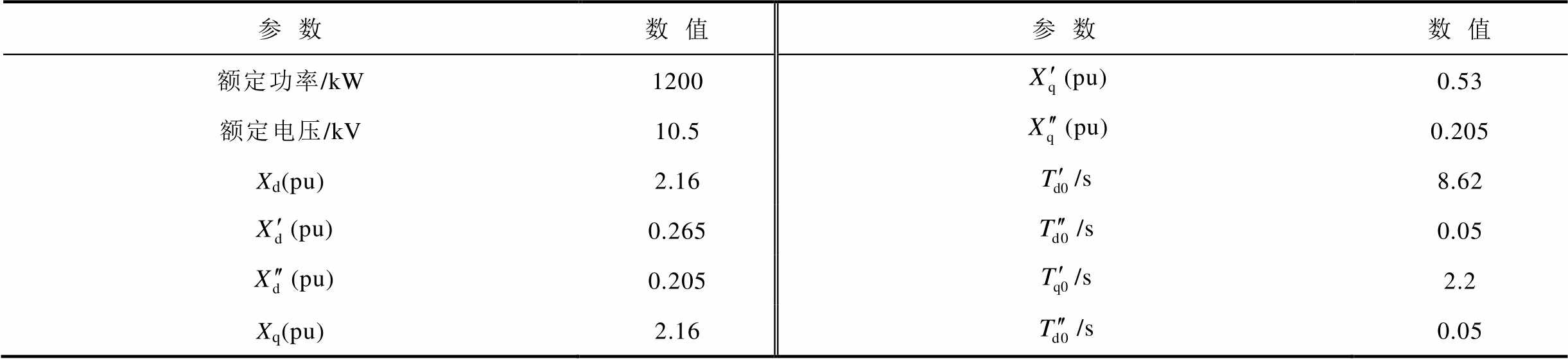
参数数值参数数值 额定功率/kW1200(pu)0.53 额定电压/kV10.5(pu)0.205 Xd(pu)2.16/s8.62 (pu)0.265/s0.05 (pu)0.205/s2.2 Xq(pu)2.16/s0.05
算例在系统受到大扰动(三相短路)及小扰动(负荷突增)时,根据DFIG等效惯量控制环节比例系数的不同分别设置五个不同场景,具体参数见表5。
表5 DFIG等效虚拟惯量控制环节比例系数
Tab.5 Equivalent proportional coefficient of virtual inertia control of DFIG

场景KSKRHeqSHeqR A000.81.250 B3000.81.2537.5 C201017 D030-24 E1020-3.5
不同场景下,双馈风机和同步发电机输出电磁功率见表6。
表6 系统发生三相短路时同步发电机有功功率
Tab.6 Active power output of generators when three-phase short circuit occurs
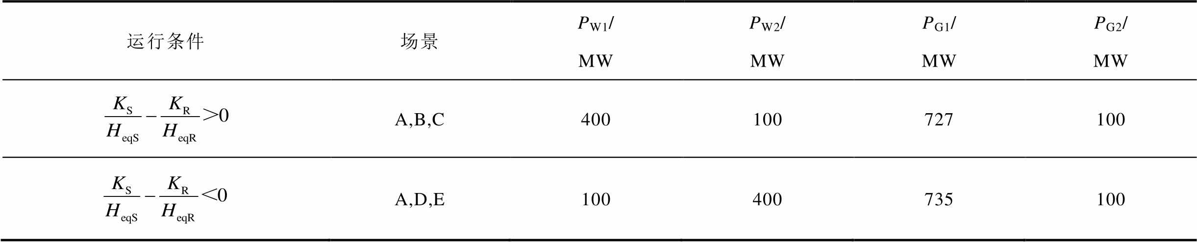
运行条件场景PW1/MWPW2/MWPG1/MWPG2/MW A,B,C400100727100 A,D,E100400735100
5.1.1 三相短路故障—— 仿真分析
仿真分析
负荷L1、L2有功功率分别为1100MW和200MW,设置母线B8发生三相接地短路故障,故障持续时间0.1s,故障前后系统频率、系统转速、风机有功功率及系统功角波动情况如图5所示,系统功角首摆稳定性评估结果见表7。
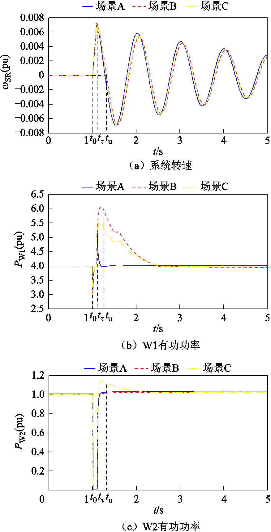
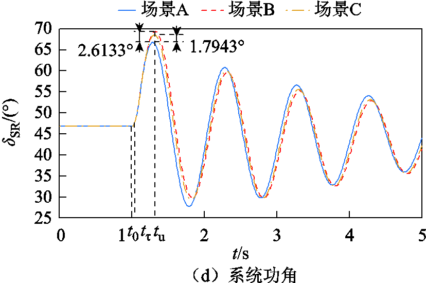
图5 三相短路时系统仿真波形Ⅰ
Fig.5 Waveforms when three-phase short circuit occurs Ⅰ
表7 三相短路时系统功角首摆稳定性评估指标及系统加速和减速阶段时间
Tab.7 Stability evaluation index and acceleration and deceleration time of the system under three-phase short circuit

运行条件场景|ΔδSR_max|/(°)t0/stτ/stu/s A20.01231.01.11.29 B22.62561.01.11.32 C21.80661.01.11.31 A3.45881.01.11.24 D2.1521.01.11.21 E3.31141.01.11.23
如图5所示,在 时段,系统发生三相短路故障,系统转速ωSR从ω0加速到ωτ,系统处于加速阶段,W1及W2机端电压分别跌落至0.38(pu)及0.23(pu)。由于机端电压跌落至0.4(pu)以下时,DFIG低电压穿越控制环节响应,正常运行状态下的有功功率积分环节被闭锁,此时不能通过改变DFIG有功功率参考值为电网提供动态有功功率支撑[26]。
在 时段,故障清除,系统转速ωSR从ωτ减速到ω0,DFIG机端电压迅速恢复,双馈风机W1、W2虚拟惯量响应系统频率变化[27],输出电磁功率增加,如图5b、图5c所示。
与场景A相比,场景B、场景C情况下,由于DFIG等效惯量控制比例系数
 ,在系统减速阶段DFIG提供的暂态能量
 ,系统暂态能量
 ,系统功角首摆最大偏移量的绝对值
 ,系统功角首摆稳定性减弱。与场景C相比较,场景B情况下DFIG等效惯量控制比例系数增大,系统功角首摆稳定性减弱,如图5d所示。
由表7可知,场景B、场景C情况下功角最大首摆偏移量绝对值|ΔδSR_max|比场景A情况下增加2.613 3°和1.794 3°,表明系统发生三相短路故障时,DFIG等效惯量控制比例系数大于零使得系统功角首摆稳定性减弱,且DFIG等效惯量控制比例系数绝对值增加不利于系统功角首摆稳定。
5.1.2 三相短路故障——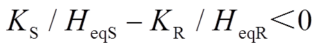 仿真分析
仿真分析
负荷L1、L2有功功率分别为200MW和1 100MW,设置母线B8处发生三相接地短路故障,持续时间0.05s,故障前后系统频率、系统转速、联络线功率、风机有功输出及系统功角波动情况如图6所示,系统功角首摆稳定性评估结果见表7。
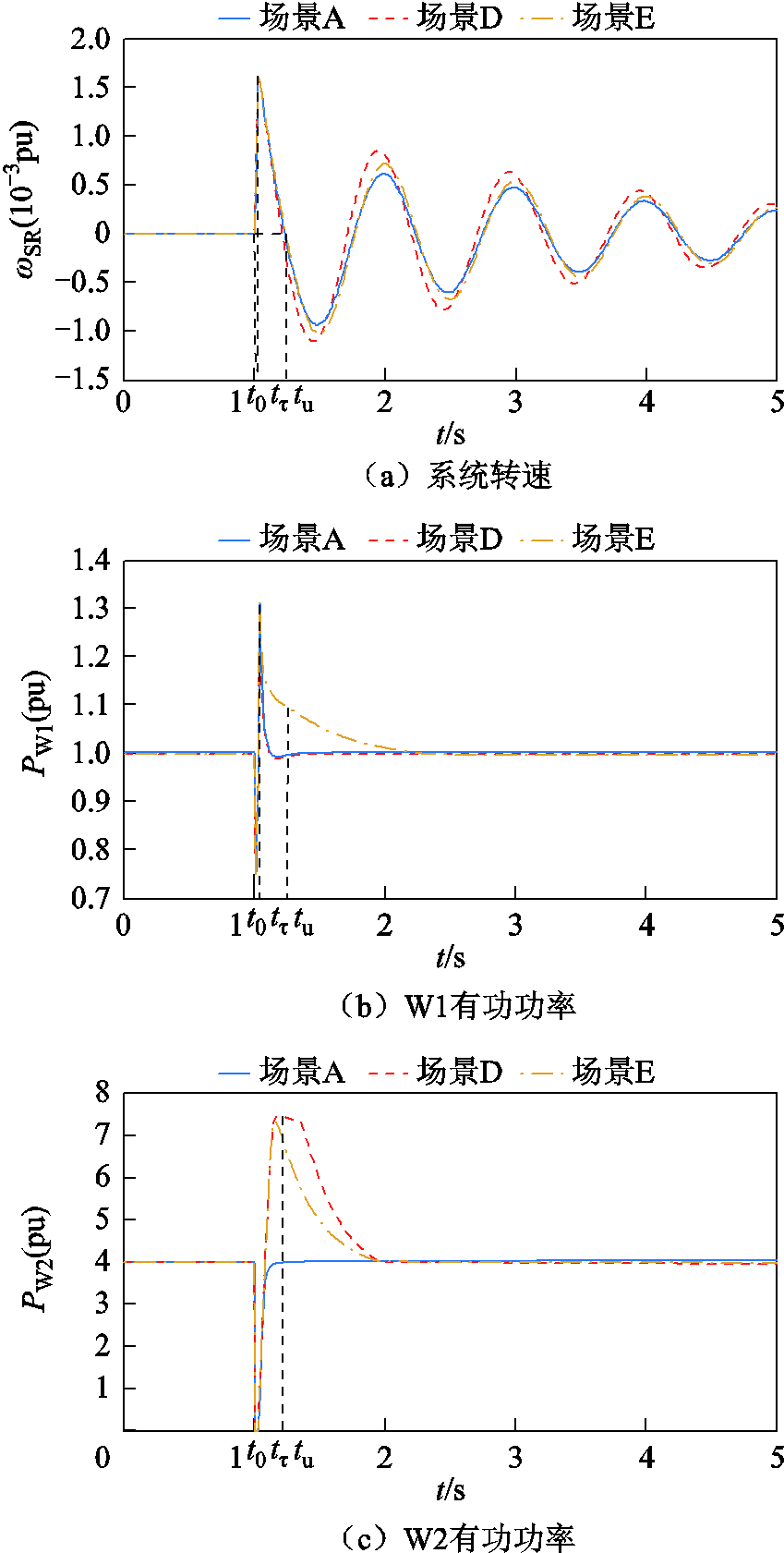
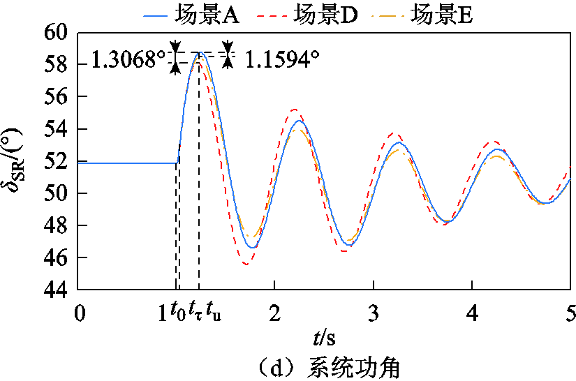
图6 三相短路时系统仿真波形Ⅱ
Fig.6 Waveforms when three-phase short circuit occursⅡ
在时段,系统发生三相短路故障,系统转速ωSR从ω0加速到ωτ,系统处于加速阶段,W1及W2机端电压分别跌落至0.3(pu)及0.24(pu),不能为电网提供动态有功功率支撑。在 时段,故障结束,系统转速ωSR从ωτ减速到ω0,系统处于减速阶段,双馈风机W1、W2虚拟惯量响应,输出电磁功率增加,如图6b、图6c所示。
与场景A相比,场景D、场景E情况下,DFIG等效惯量控制比例系数 <
< 在系统减速阶段DFIG提供的暂态能量
 ,系统暂态能量
 ,系统功角首摆最大偏移量绝对值
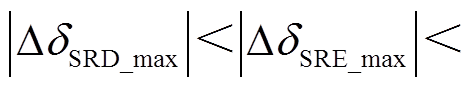
 ,系统功角首摆稳定性增强。与场景E相比较,场景D情况下DFIG等效惯量控制比例系数绝对值增加,功角首摆稳定性增强,如图6d所示。
由表7可知,场景D、场景E情况下功角最大首摆偏移量绝对值|ΔδSR_max|比场景A情况下减小1.306 8°和1.159 4°,表明系统发生三相短路故障时,DFIG等效惯量控制比例系数小于零使得系统功角首摆稳定性增强,且DFIG等效惯量控制比例系数绝对值增加有利于系统功角首摆稳定。
5.2.1 负荷突增—— 仿真分析
仿真分析
负荷L1、L2有功功率分别为800MW和300MW,设置1.0~2.0s负荷L2增加500MW,系统功角反向摆动。扰动前后系统频率、系统转速、风机有功输出及系统功角波动情况如图7所示,系统功角首摆稳定性评估结果见表8。
表8 负荷突增时时系统功角首摆稳定性评估指标及系统加速及减速阶段时间
Tab.8 Stability evaluation index and acceleration and deceleration time of the system during load sudden change
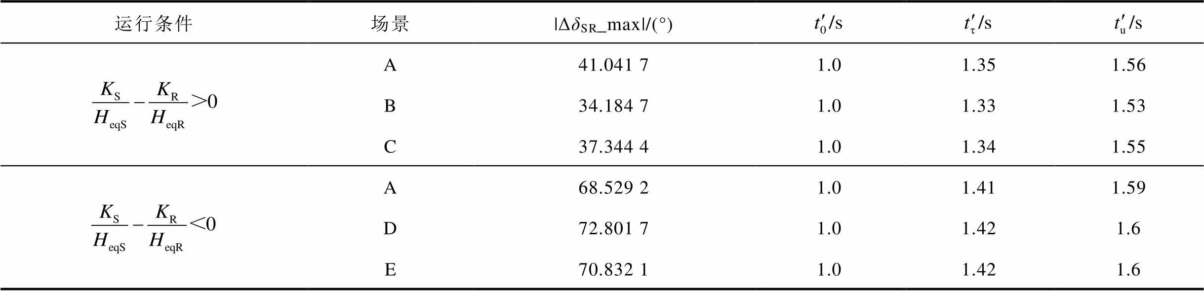
运行条件场景|ΔδSR_max|/(°) A41.041 71.01.351.56 B34.184 71.01.331.53 C37.344 41.01.341.55 A68.529 21.01.411.59 D72.801 71.01.421.6 E70.832 11.01.421.6
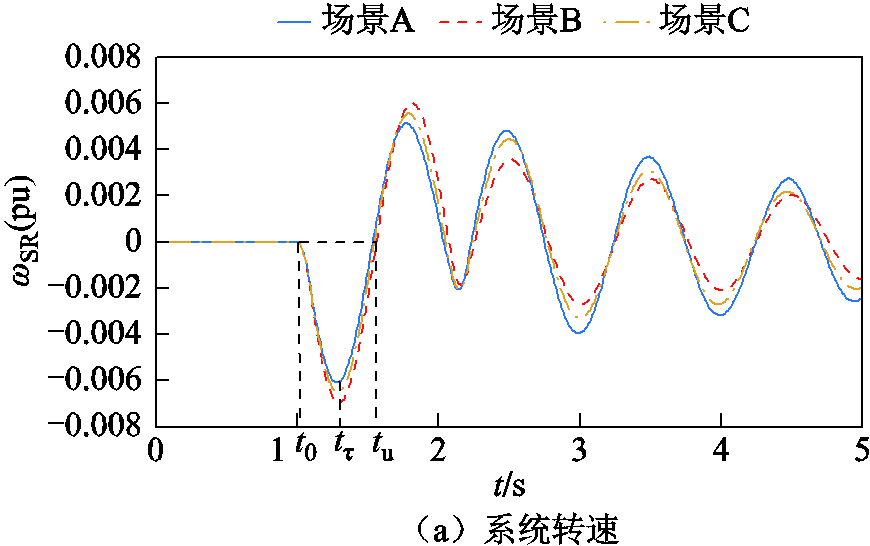
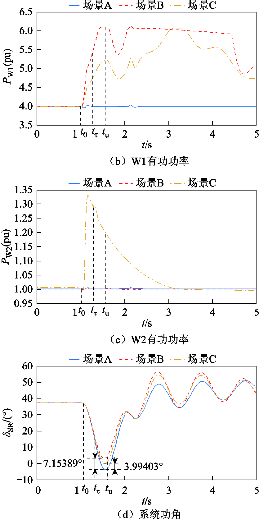
图7 负荷突增时系统仿真波形Ⅰ
Fig.7 Simulation waveforms during load sudden changeⅠ
系统负荷突增,双馈风机W1、W2虚拟惯量响应,输出电磁功率增加。由于惯量响应后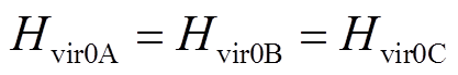 ,Hvir0首先迅速达到最大值,随后开始下降,因此DFIG在系统加速阶段提供的暂态能量大于减速阶段,即
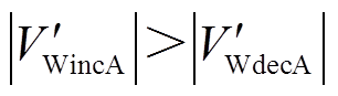 ,
, ,
, ,DFIG最终提供的暂态能量主要由系统加速阶段DFIG提供的暂态能量决定。
与场景A相比,场景B、场景C情况下,DFIG等效惯量控制比例系数
 在
在 时段,系统转速ωSR从
 反向加速到
反向加速到 ,系统处于加速阶段,DFIG提供的暂态能量
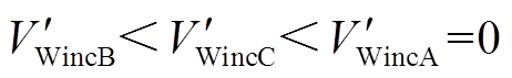 。
。
在![]() 时段,系统转速ωSR从反向减速到,系统处于减速阶段,DFIG提供的暂态能量
时段,系统转速ωSR从反向减速到,系统处于减速阶段,DFIG提供的暂态能量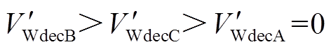 。
。
因此,DFIG最终提供的暂态能量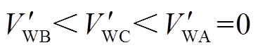 ,系统暂态能量
 ,系统功角首摆最大偏移量的绝对值
 ,系统功角首摆稳定性增强。与场景C相比,场景B情况下DFIG等效惯量控制比例系数绝对值增大,系统功角首摆稳定性增强,如图7d所示。
由表8可知,场景B、场景C情况下功角最大首摆偏移量绝对值|ΔδSR_max|比场景A情况下减小7.153 89°和3.994 03°,系统功角首摆稳定性增强,且DFIG等效惯量控制比例系数增加有利于系统功角首摆稳定。
5.2.2 负荷突增—— 仿真分析
仿真分析
负荷L1、L2有功功率分别为300MW和800MW,设置1.0~2.0s负荷L1突增800MW,系统功角反向摆动。扰动前后系统频率、系统转速、风机有功输出及系统功角波动情况如图8所示,系统功角首摆稳定性评估结果见表8。
DFIG惯量响应后 ,在系统加速阶段提供的暂态能量大于减速阶段,在时段,系统转速ωSR从反向加速到
 ,系统处于加速阶段,DFIG提供的暂态能量
 。
。
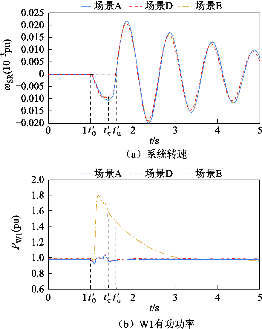
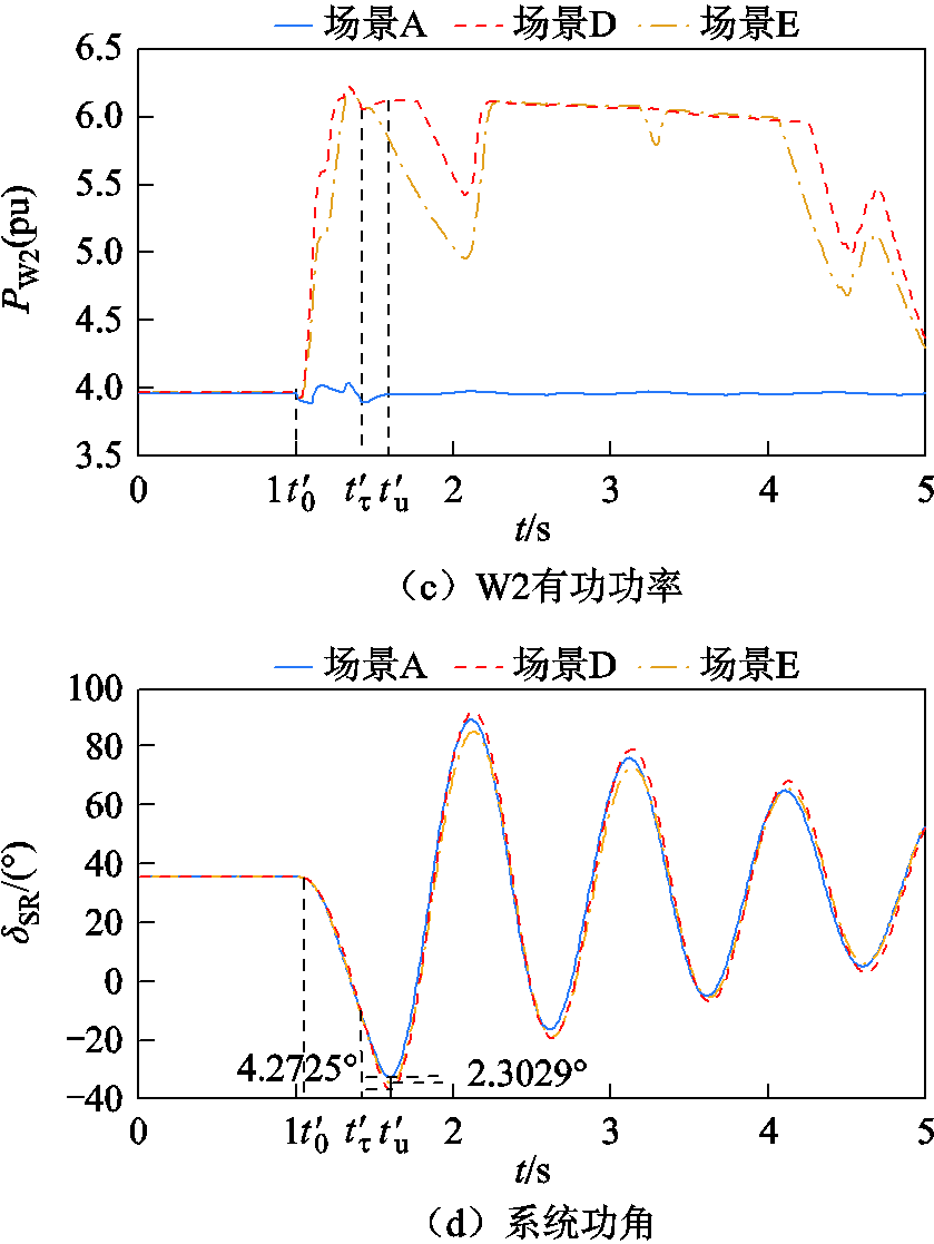
图8 负荷突增时系统仿真波形Ⅱ
Fig.8 Simulation waveforms during load sudden change Ⅱ
在 时段,系统转速ωSR从反向减速到,系统处于减速阶段,DFIG提供的暂态能量
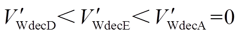 。
。
因此,DFIG最终提供的暂态能量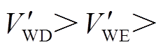
 ,系统暂态能量
 ,系统功角首摆绝对值
 ,系统功角首摆稳定性减弱。与场景E相比,场景D情况下DFIG等效惯量控制比例系数绝对值增大,系统功角首摆稳定性进一步减弱,如图8d所示。
由表8可知,场景D、场景E情况下系统功角最大首摆偏移量绝对值|ΔδSR_max|比场景A情况下增加4.272 5°和2.302 9°,系统功角首摆稳定性减弱,且DFIG等效惯量控制比例绝对值增加不利于系统功角首摆稳定。
本文研究送受端区域内DFIG同时附加虚拟惯量控制,系统发生三相短路故障及负荷突增时,两区域互联系统DFIG等效惯量控制比例系数对系统加速及减速过程中暂态能量的影响,进而研究系统功角首摆稳定的内在机理,并通过系统功角首摆最大偏移量对系统功角首摆稳定性进行评估,分析结果表明:
1)系统发生三相短路故障时,系统功角正向摆动,DFIG惯量响应改变系统减速期间暂态能量,若两区域互联系统DFIG等效惯量控制环节比例系数大于零,系统功角首摆稳定性减弱,且DFIG等效惯量控制环节比例系数绝对值减小有利于系统功角首摆稳定;反之,不利于系统功角首摆稳定。
2)系统负荷突增时,系统功角反向摆动,DFIG惯量响应改变系统加速及减速期间暂态能量,若两区域互联系统DFIG等效惯量控制环节比例系数大于零,系统功角首摆稳定性增强,且DFIG等效惯量控制环节比例系数绝对值增加有利于系统功角首摆稳定;反之,不利于系统功角首摆稳定。
参考文献
[1] Liu Juelin, Yang Zhifang, Yu Juan, et al. Coordinated control parameter setting of DFIG wind farms with virtual inertia control[J]. International Journal of Electrical Power & Energy Systems, 2020, 122(12): 106167.
[2] 章艳, 高晗, 张萌. 不同虚拟同步机控制下双馈风机系统频率响应差异研究[J]. 电工技术学报, 2020, 35(13): 2889-2900.
Zhang Yan, Gao Han, Zhang Meng. Research on frequency response difference of doubly-fed induction generator system controlled by different virtual synchronous generator controls[J]. Transactions of China Electrotechnical Society, 2020, 35(13): 2889-2900.
[3] 赵晶晶, 李敏, 何欣芹, 等. 基于限转矩控制的风储联合调频控制策略[J]. 电工技术学报, 2019, 34(23): 4982-4990.
Zhao Jingjing, Li Min, He Xinqin, et al. Coordinated control strategy of wind power and energy storage in frequency regulation based on torque limit control[J]. Transactions of China Electrotechnical Society, 2019, 34(23): 4982-4990.
[4] 颜湘武, 宋子君, 崔森, 等. 基于变功率点跟踪和超级电容器储能协调控制的双馈风电机组一次调频策略[J]. 电工技术学报, 2020, 35(3): 530-541.
Yan Xiangwu, Song Zijun, Cui Sen, et al. Primary frequency modulation strategy of doubly-fed induction generator based on variable power point tracking and coordinated control of supercapacitor energy storage[J]. Transactions of China Electrote-chnical Society, 2020, 35(3): 530-541.
[5] 颜湘武, 王德胜, 杨琳琳, 等. 直驱风机惯量支撑与一次调频协调控制策略[J]. 电工技术学报, 2021, 36(15): 3282-3292.
Yan Xiangwu, Wang Desheng, Yang Linlin, et al. Coordinated control strategy of inertia support and primary frequency regulation of PMSG[J]. Transactions of China Electrotechnical Society, 2021, 36(15): 3282-3292.
[6] 郝正航. 双馈风电机组的暂态行为及其对电力系统稳定性影响[D]. 天津: 天津大学, 2011.
[7] 张祥宇, 王爽, 王毅, 等. 含可控惯量发电系统的功角暂态稳定分析与惯性控制策略[J]. 电力建设, 2018, 39(1): 106-112.
Zhang Xiangyu, Wang Shuang, Wang Yi, et al. Power angle transient stability analysis and inertia control strategy of power generation system with controllable inertia[J]. Electric Power Construction, 2018, 39(1): 106-112.
[8] 刘斯伟. 并网双馈风电机组对电力系统暂态稳定性的影响机理研究[D]. 北京: 华北电力大学(北京), 2016.
[9] 赵振元, 陈维荣, 戴朝华, 等. 系统惯性时间常数对互联电网暂态稳定水平的影响[J]. 电网技术, 2012, 36(1): 102-107.
Zhao Zhenyuan, Chen Weirong, Dai Chaohua, et al. Influence of system inertia time constant on transient stability level of interconnected power grid[J]. Power Syetem Technology, 2012, 36(1): 102-107.
[10] 张明理, 徐建源, 李佳珏. 含高渗透率风电的送端系统电网暂态稳定研究[J]. 电网技术, 2013, 37(3): 740-745.
Zhang Mingli, Xu Jianyuan, Li Jiajue. Research on transient stability of sending power grid containing high proportion of wind power[J]. Power Syetem Technology, 2013, 37(3): 740-745.
[11] 王哲. 惯量可控发电机组对电力系统动态特性影响分析[D]. 北京: 华北电力大学(北京), 2019.
[12] Kimbark E W. Power system stability: synchronous machines[J]. New York: John Wiley, 1948.
[13] 罗远翔, 杨仁刚, 蔡国伟, 等. 大容量风电接入系统对网络暂态能量的影响[J]. 电力系统及其自动化学报, 2014, 28(1): 76-80.
Luo Yuanxiang, Yang Rengang, Cai Guowei, et al. Influence of large capacity wind power access system on network transient energy[J]. Proceedings of the CSU-EPSA, 2014, 28(1): 76-80.
[14] 姜惠兰, 姜哲, 李天鹏, 等. 风机转子撬棒投切对电力系统暂态稳定性的影响[J]. 电网技术, 2016, 40(8): 2383-2388.
Jiang Huilan, Jiang Zhe, Li Tianpeng, et al. Impact of rotor crowbar switching on transient stability of power system[J]. Power System Technology, 2016, 40(8): 2383-2388.
[15] 吴玉璋. 风电场接入对电力系统暂态稳定影响研究[D]. 天津: 天津大学, 2017.
[16] 罗远翔, 杨仁刚, 刘铖, 等. TCSC提高大容量风电接入系统的稳定性及控制策略[J]. 电测与仪表, 2014(4): 35-39.
Luo Yuanxiang, Yang Rengang, Liu Cheng, et al. Control strategy of TCSC for stability improvement in power systems integrated with large scale wind farms[J]. Electrical Measurement & Instrumentation, 2014(4): 35-39.
[17] 周明, 董哲, 李洪宇, 等. 风机故障后有功控制对系统暂态功角失稳的影响机理(英文)[J]. 电网技术, 2019, 43(4): 1280-1293.
Zhou Ming, Dong Zhe, Li Hongyu, et al. Influence mechanism of active power control on transient angle instability of wind turbine system after fault[J]. Power System Technology, 2019, 43(4): 1280-1293.
[18] 于珍, 沈沉, 张雪敏. 双馈风机故障穿越后功率恢复速率对系统暂态稳定的影响分析[J]. 中国电机工程学报, 2018, 38(13): 3781-3791, 4019.
Yu Zhen, Shen Shen, Zhang Xuemin. Influence of power recovery rate on transient stability of doubly-fed fan after fault crossing[J]. Proceedings of the CSEE, 2018, 38(13): 3781-3791, 4019.
[19] 牟澎涛, 赵冬梅, 王嘉成. 大规模风电接入对系统功角稳定影响的机理分析[J]. 中国电机工程学报, 2017, 37(5): 1325-1334.
Mou Pengtao, Zhao Dongmei, Wang Jiacheng. Mechanism analysis of influence of large-scale wind power access on system power angle stability[J]. Proceedings of the CSEE, 2017, 37(5): 1325-1334.
[20] 林俐, 杨以涵. 基于扩展等面积定则的含大规模风电场电力系统暂态稳定性分析[J]. 电力系统保护与控制, 2012, 40(12): 105-110, 115.
Lin Li, Yang Yihan. Transient stability analysis of power system with large scale wind farm based on extended equal area rule[J]. Power System Protection and Control, 2012, 40(12): 105-110, 115.
[21] 李世春, 邓长虹, 龙志君, 等. 风电场等效虚拟惯性时间常数计算[J]. 电力系统自动化, 2016, 40(7): 22-29.
Li Shichun, Deng Changhong, Long Zhijun, et al. Calculation of equivalent virtual inertia time constant of wind farm[J]. Automation of Electric Power Systems, 2016, 40(7): 22-29.
[22] 刘皓明, 任秋业, 张占奎, 等. 双馈风机等效惯性时间常数计算及转差率反馈惯量控制策略[J]. 电力系统自动化, 2018, 42(17): 49-57.
Liu Haoming, Ren Qiuye, Zhang Zhankui, et al. Calculation of equivalent inertia time constant and control strategy of slight feedback inertia for double-fed fan[J]. Automation of Electric Power Systems, 2018, 42(17): 49-57.
[23] 李春艳, 孙元章, 彭晓涛, 等. 采用广域测量信息反馈的广域PSS参数设计[J]. 电力系统自动化, 2009, 33(18): 6-11.
Li Chunyan, Sun Yuanzhang, Peng Xiaotao, et al. Wide-area PSS parameter design using wide-area measurement feedback[J]. Automation of Electric Power Systems, 2009, 33(18): 6-11.
[24] Zhang Xiangyu, Zhu Zhengzhen, Fu Yuan, et al. Multi-objective virtual inertia control of renewable power generator for transient stability improvement in interconnected power system[J]. International Journal of Electrical Power and Energy Systems, 2020, 117: 105641.1-105641.12.
[25] Shao Haoshu, Cai Xu, Zhou Dangsheng, et al. Equivalent modeling and comprehensive evaluation of inertia emulation control strategy for DFIG wind turbine generator[C]//2019 10th International Conference on Power Electronics and ECCE Asia, Busan, 2019: 3164-3170.
[26] 袁辉, 宋晓喆, 孙福寿, 等. 弱电网中低电压穿越控制策略导致的双馈风机失稳机理分析[J]. 电力自动化设备, 2020, 40(9): 50-58.
Yuan Hui, Song Xiaozhe, Sun Fushou, et al. Analysis on instability mechanism of double-fed fan caused by low voltage crossing control strategy in weak power grid[J]. Electric Power Automation Equipment, 2020, 40(9): 50-58.
[27] 张磊, 张闯, 罗毅, 等. 电网友好型双馈感应发电机的暂态协调控制策略[J]. 电力系统自动化, 2019, 43(12): 44-50, 112.
Zhang lei, Zhang Chuang, Luo Yi, et al. Transient coordinated control strategy of grid friendly double-fed induction generator[J]. Automation of Electric Power Systems, 2019, 43(12): 44-50, 112.
(编辑 赫蕾)
Abstract Compared with traditional synchronous machines, doubly-fed Induction Generator (DFIG) lacks inertial response capability. Therefore, when a large-scale DFIG is connected to a power system suffering from large or small disturbances (three-phase short circuit, sudden load increase, etc.), the system inertial response capability is severely lacking and the problem of transient power angle stability is highlighted. With the continuous improvement of the DFIG virtual inertia control technology, the DFIG can provide dynamic inertia support for the system. Therefore, there is an urgent necessity to carry out research on the mechanism of the effect of the DFIG’s virtual inertia on the first swing stability of the system power angle. To address these issues, this paper proposes a mechanism analysis method for the effect of equivalent proportional coefficient of virtual inertia control of DFIG on stability of first swing of power angle.
Firstly, the equivalent model of two regional inertia centers is derived, and the influence of DFIG virtual inertia on the rotor motion equations of the two regions is analyzed. Secondly, from the perspective of the transient energy of the system, the influence of the equivalent proportional coefficient of virtual inertia control of DFIG in the two regions on the transient energy during the acceleration and deceleration of the system is studied when the swing direction of system power angle are different and the swing direction of influence mechanism on the first swing stability of system is further studied. Finally, the stability of the system was evaluated by the maximum deviation of the system power angle and a simulation model of the two-region interconnection system was built in PSASP to verify the proposed theory.
Considering the DFIG in sending and receiving ends with additional inertia control, the following conclusions can be drawn from the simulation analysis: ①When a three-phase short circuit fault occurs in the system, the power angle of the system swings in the positive direction, and the DFIG inertia response changes the transient energy during system deceleration. If the equivalent proportional coefficient of the DFIG’s virtual inertia control link is greater than zero, the stability of the system power angle first swing is weakened, and the absolute value of the equivalent proportional coefficient of the DFIG’s virtual inertia control link is reduced, which is conducive to the stability of the system power angle first swing, otherwise, it is not conducive to the stability of the system power angle first swing. ②When the system load suddenly increases, the power angle of the system swings in the opposite direction, and the DFIG inertia response changes the transient energy during the system acceleration and deceleration. If the equivalent proportional coefficient of the DFIG’s virtual inertia control link is greater than zero, the stability of the system power angle first swing is enhanced, and the absolute value of the equivalent proportional coefficient of the DFIG’s virtual inertia control link is increased, which is conducive to the stability of the system power angle first swing, otherwise, it is not conducive to the stability of the system power angle first swing.
keywords:Doubly-fed induction generator(DFIG), equivalent proportional coefficient of virtual inertia control, transient energy function, the first swing stability of power angle
DOI:10.19595/j.cnki.1000-6753.tces.211305
中图分类号:TM614
国家自然科学基金联合基金重点项目(U1910216)和山西省科技重大专项(20181102028)资助。
收稿日期 2021-08-17
改稿日期 2021-11-18
王 科 女,1995年生,硕士研究生,研究方向为新能源电力系统分析与控制。E-mail:15536816118@163.com
秦文萍 女,1972年生,教授,博士生导师,研究方向为电力系统可靠性/稳定性分析、微电网运行与控制、交直流混合微电网保护等。E-mail:qinwenping@tyut.edu.cn(通信作者)
(编辑 赫蕾)