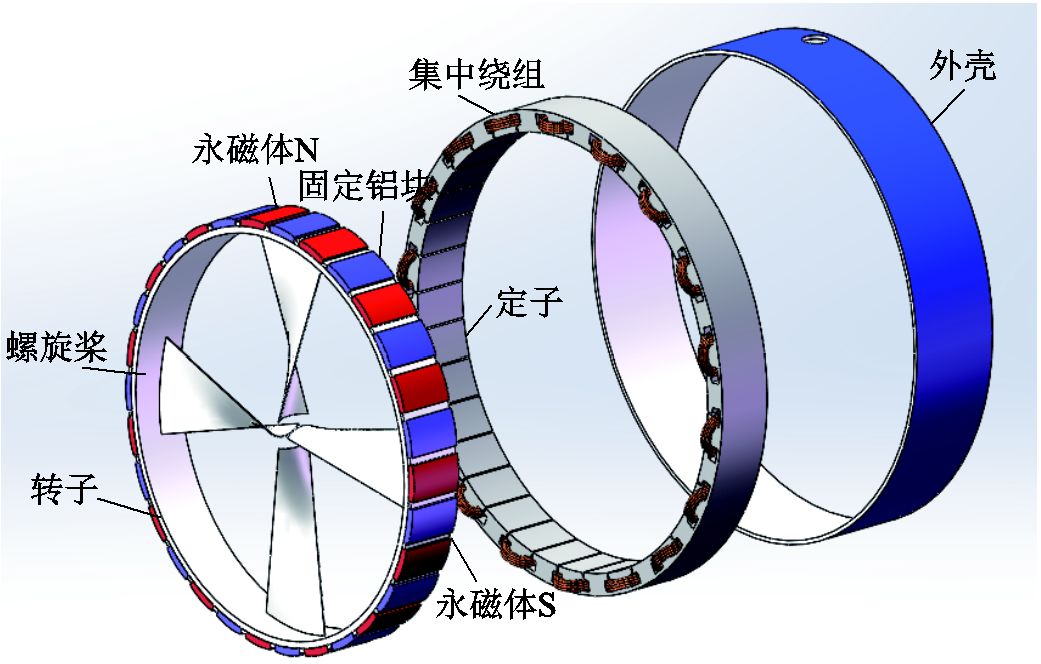
图1 六相永磁容错轮缘推进电机结构示意图
Fig.1 Schematic diagram of six-phase FTPM-RDM
摘要 针对永磁容错轮缘推进电机传统电流滞环控制策略转矩脉动大的问题,提出一种预测占空比电流滞环控制策略。在固定采样频率下,通过当前时刻转子位置、角速度及母线电压预测电流滞环宽度,进而根据电流相对滞环位置预测占空比来实现闭环控制,同时结合故障容错控制策略可实现电机一相开路和短路故障容错控制。利用Matlab/Simulink搭建仿真模型,设计并调试以StarSim为核心的硬件实验平台,仿真和实验结果证明所提出的预测占空比电流滞环控制策略可有效提高电流控制精度,降低电机转矩脉动,同时保留了传统电流滞环控制算法简单和响应速度快的特点。
关键词:永磁容错轮缘推进电机 H桥逆变电路 预测占空比 StarSim
随着海上贸易的高速发展,船舶所需吨位和功率日益提高,传统推进系统在空间、能耗、噪声等方面劣势日趋明显[1]。轮缘推进器(Rim Drive Motor, RDM)将螺旋桨、推进电机、轴承集成一体,具有结构紧凑、效率高、绿色环保等突出优点,是现代电力推进技术的革命性创新[2]。RDM内置集成电机主要为永磁同步电机(Permanent Magnet Synchronous Motor, PMSM)[3]。永磁容错电机(Fault-Tolerant Permanent Magnet Motor, FTPMM)是绕组独立的PMSM,不仅效率高、体积小,还具有良好的容错性和可靠性[4]。永磁容错轮缘推进电机(Fault-Tolerant Permanent Magnet Rim Drive Motor, FTPM-RDM)采用FTPMM作为RDM的内置电机,既可以提高船舶空间利用率和效率,又可明显提升推进系统的稳定性和可靠性[5]。
近年来,国内外许多学者对id=0的矢量控制算法进行了深入的研究,研究热点主要有内外环双PI控制、模型预测电流控制、电流滞环跟踪脉宽调制等。传统PI控制策略因其算法简单被广泛用作电机电流和转速控制器,但PI控制器存在参数设计及整定困难等局限性,限制了它的进一步发展[6]。模型预测电流控制,具备原理直观、设计灵活、多目标协同等优点,但是对于多相FTPM-RDM的众多电压矢量,会存在计算量大、权重系数选取复杂、滚动优化循环次数多的缺点[7]。与此同时,上述两种控制策略在FTPM-RDM发生绕组短路时很难提供合理的解决方案。
电流滞环跟踪脉宽调制(Current Hysteresis Band Pulse Width Modulation, CHBPWM)策略具备控制算法简单、易实现、动态性能好、鲁棒性强的优良特性,目前已经成功地应用在众多电力变换系统中[8]。相比于内外环双PI控制、模型预测电流控制,FTPM-RDM采用CHBPWM控制策略,无需各相矢量联合,可直接对各相绕组进行单独控制,具备算法简单、响应迅速的优势[9]。传统三相PMSM由于绕组相互影响,无法精准确定单个采样周期每相绕组相电压矢量大小,因此只能实现传统CHBPWM策略,存在开关频率不固定问题,同时不具备故障容错性能[10]。相比传统PMSM,FTPM-RDM的绕组结构和H桥逆变器可完美结合CHBPWM算法,实现精准确定每相绕组施加的电压矢量,进而对单个采样周期CHBPWM控制进行具体分析并提出优化算法[11]。同时当FTPM-RDM出现开路、短路故障时,可通过直接控制正常相电流对故障相进行补偿,快速实现电机开路短路容错控制[12]。因此采用CHBPWM策略控制FTPM-RDM,可以获得兼备响应快速性、易实现、可靠性的电力推进方案。
传统CHBPWM采用单个采样周期单开关动作的控制方式,受数字控制器运算速度和功率器件允许开关频率的限制,实际实现的传统CHBPWM控制的采样频率较低,且开关频率不大于采样频率的一半[13]。因单个采样周期时间久且开关动作不变,故FTPM-RDM应用传统CHBPWM存在相电流脉动大、畸变率高从而造成转矩脉动大的缺点。
本文通过综合分析FTPM-RDM应用CHBPWM控制的优势和应用传统CHBPWM的缺陷,并参考文献[14]应用于传统三相PMSM的变占空比CHBPWM控制策略,提出一种适用于FTPM-RDM的预测占空比CHBPWM控制策略。该算法在保留传统CHBPWM算法简单、响应快速的同时有效降低了电流脉动、电流畸变率和转矩脉动,并且实现了电机一相开路、短路容错控制。最后通过仿真和实验验证了预测占空比CHBPWM控制策略的可行性。
六相FTPM-RDM结构示意图如图1所示,定子采用单层集中绕组,相邻绕组的相位差为60°,每相绕组间采用电枢隔离齿,各相绕组相互独立,有效地实现了物理、电气、热和磁隔离[15]。FTPM-RDM每相由如图2所示的H桥逆变电路供电。
图1 六相永磁容错轮缘推进电机结构示意图
Fig.1 Schematic diagram of six-phase FTPM-RDM
为了保证控制效果,在对FTPM-RDM进行建模时,做出如下假设:①忽略漏磁通、磁滞损耗的影响;②各相绕组参数恒定且完全对称;③各相绕组的电动势波形为正弦波。
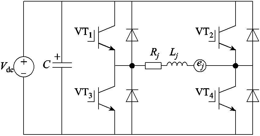
图2 单相H桥逆变电路
Fig.2 Single-phase H bridge inverter
基于以上假设,可推导出六相FTPM-RDM在自然坐标系下的数学模型。
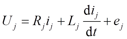
电压方程为
 (1)
(1)
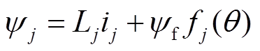
磁链方程为
 (2)
(2)
电磁转矩方程为
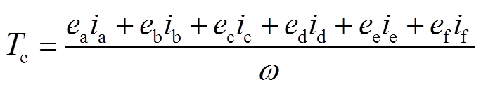 (3)
(3)
运动方程为
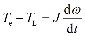 (4)
(4)
式中,ψj为各相绕组磁链;ij为各相电流;Uj为各相电压;Rj为各相电阻;Lj各相电感;ej为各相反电动势;ψf为永磁体磁链;fj(q)为各相磁动势;q为空间电角度;Te为电磁转矩;TL为负载转矩;ω为机械角速度;J为电机转动惯量。
本文基于FTPM-RDM的结构和H桥逆变电路的特点,提出在固定采样频率下的预测占空比CHBPWM控制策略,系统结构框图如图3所示。
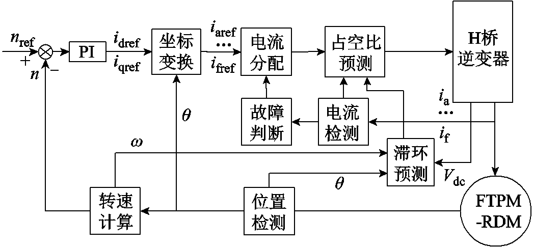
图3 FTPM-RDM控制系统结构框图
Fig.3 Block diagram of FTPM-RDM
首先,转速误差经PI和坐标变换、电流检测及故障判断得到分配的六相给定电流,将给定电流和预测滞环宽度传送到占空比预测单元,实现对FTPM-RDM的精确控制。因FTPM-RDM各相绕组独立,各相间电压、电流互不影响,故以A相为例,叙述本文所提预测占空比CHBPWM控制算法。
在CHBPWM控制下,假设A相电流ia在当前采样时刻刚好处在滞环底侧,在下一周期电流刚好从环底升至环顶再降至环底。定义环顶到环底的距离为![]() ,A相电流给定值iaref与环底的差值为预测的滞环宽度h,A相电流脉动等效图如图4所示,其中定义T为采样周期,电流上升时间占比为D,即D为占空比。
,A相电流给定值iaref与环底的差值为预测的滞环宽度h,A相电流脉动等效图如图4所示,其中定义T为采样周期,电流上升时间占比为D,即D为占空比。
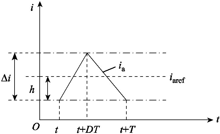
图4 CHBPWM单周期A相电流脉动等效图
Fig.4 A-phase current pulsation curve of CHBPWM in single-period
基于图2的单相H桥逆变电路,在t~(t+DT)时刻,VT1、VT4管开通,VT2、VT3管关断,A相电流处于上升阶段,在t+DT~t+T时刻,VT2、VT3管导通,VT1、VT4关断时,绕组电流处于下降阶段,忽略绕组电阻产生的压降,由FTPM-RDM电压方程式(1)可得
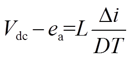 (5)
(5)
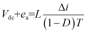 (6)
(6)
结合式(5)、式(6)可得
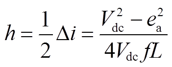 (7)
(7)
式中,f为采样频率;Vdc为母线电压;ea为A相绕组反电动势,ea可由FTPM-RDM机械角速度ω和转子位置q 求出。
确定滞环宽度h后,根据当前采样时刻ia对应的滞环位置,可预测出下一个周期A相占空比。在当前时刻,ia相对滞环位置有三种情况,即滞环下侧,滞环内侧,滞环上侧,如图5所示,其中tup、tdown分别为A相电流升、降时间。
图5a为情况1,当前采样时刻ia位于滞环下侧,即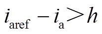 ,此时采用控制方式1,下一周期按ia先上升至环顶再下降顺序对H桥进行控制,求得A相电流升和降时间分别为
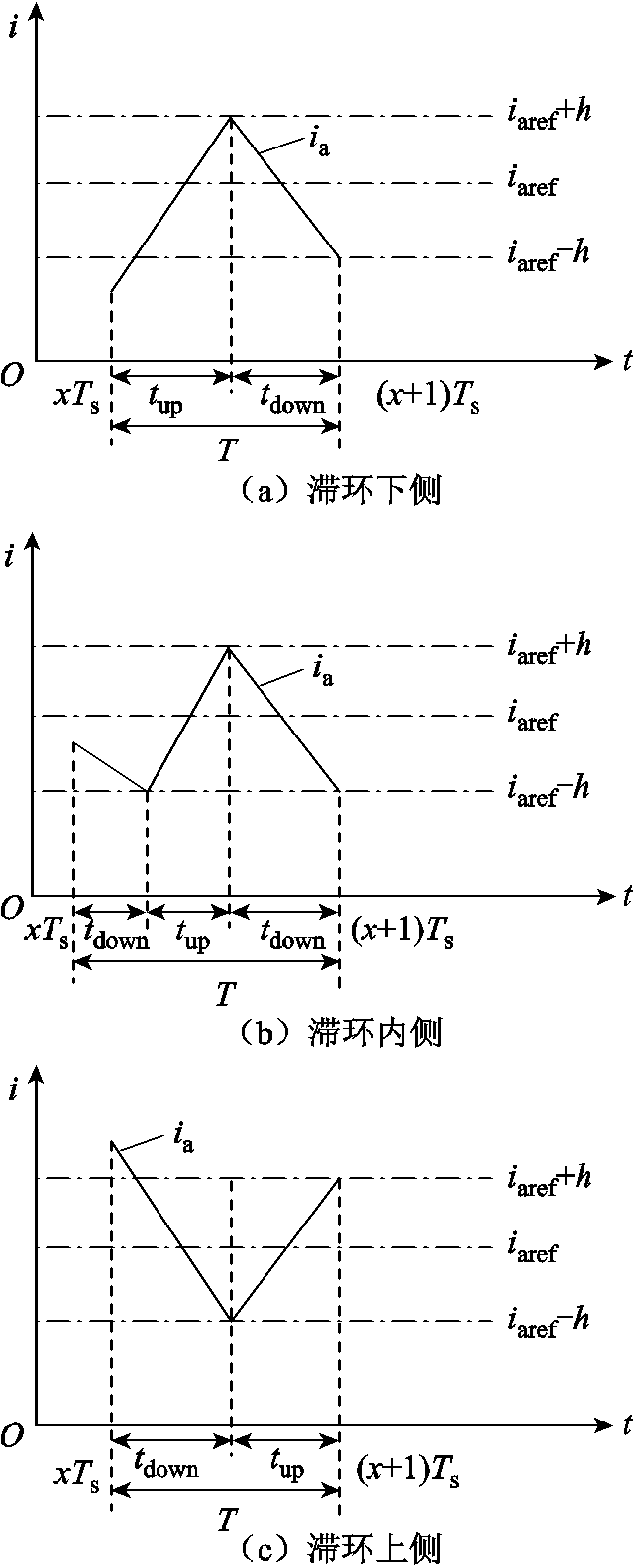
图5 A相电流相对滞环位置情况
Fig.5 Position of A-phase current relative to hysteresis band
 (8)
(8)
图5b、图5c分别为情况2、3,ia位于滞环内侧、上侧,即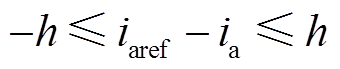 、
、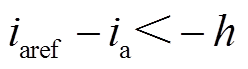 ,此时这两种情况下采用控制方式2,即下一周期按ia先下降至环底再上升顺序对H桥进行控制,求得
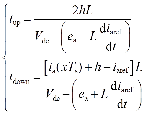 (9)
(9)
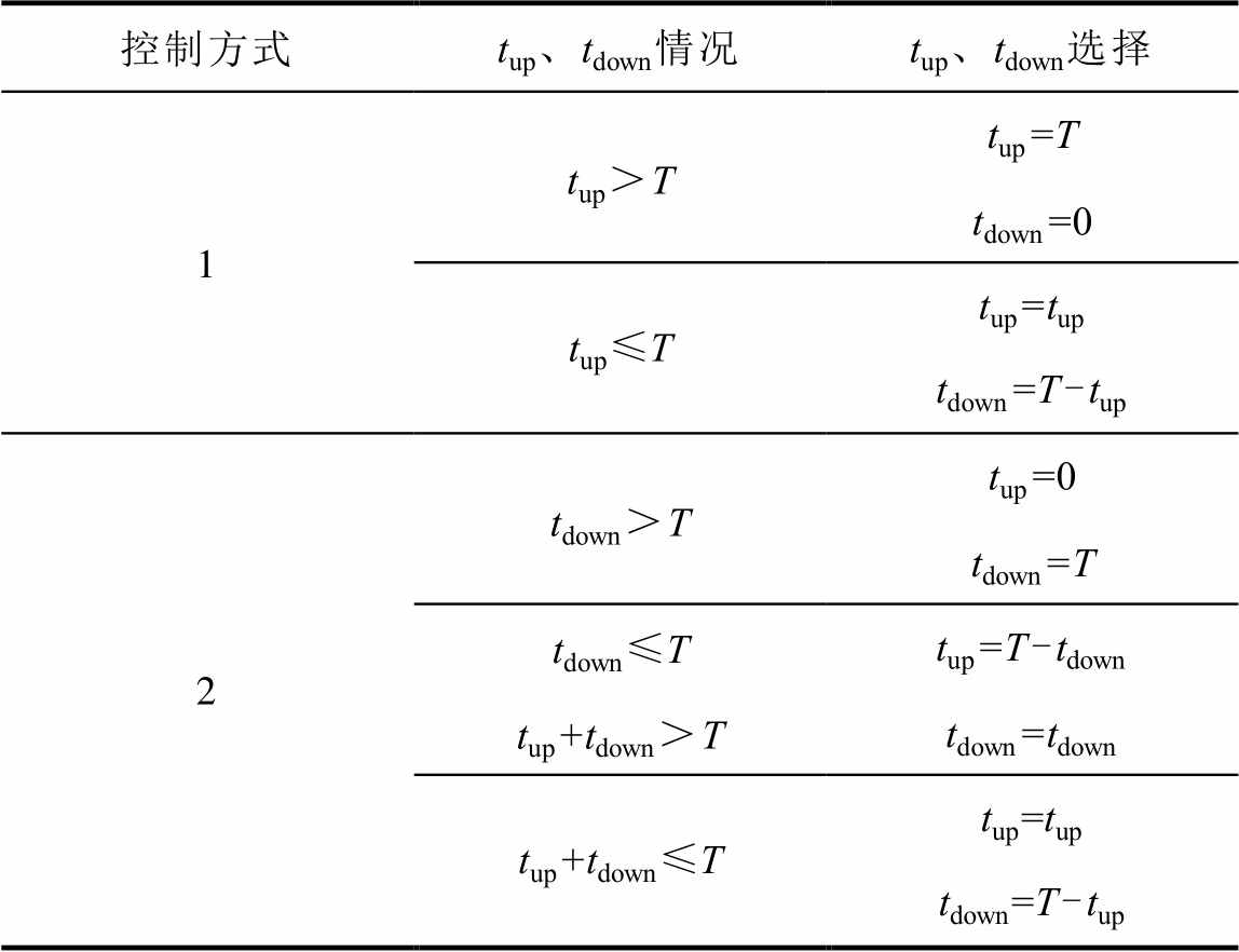
因当前采样时刻ia相对滞环位置不固定,而下一周期预测滞环宽度、电流变化率固定,此时会出现![]() 的情况。故对控制方式1、2具体分析,重新计算电流升、降时间,进而确定下一周期预测占空比,重新计算
的情况。故对控制方式1、2具体分析,重新计算电流升、降时间,进而确定下一周期预测占空比,重新计算![]() 、
、![]() 见表1。
见表1。
表1 A相电流单周期tup, tdown计算表
Tab.1 Calculation table of single cycle tup, tdown for phase A current
控制方式、情况、选择 1 2
求得占空比D后,采用PWM调制方式得到A相H桥逆变器的驱动脉冲,调制原理如图6所示。其中,ref和D的关系为:ref=2D–1,将调制得到的驱动脉冲取反,可得到两路正反互补PWM驱动脉冲控制A相H桥逆变器。因FTPM-RDM可实现各相电流的单独控制,故结合A相算法,可实现FTPM-RDM预测占空比CHBPWM闭环控制。
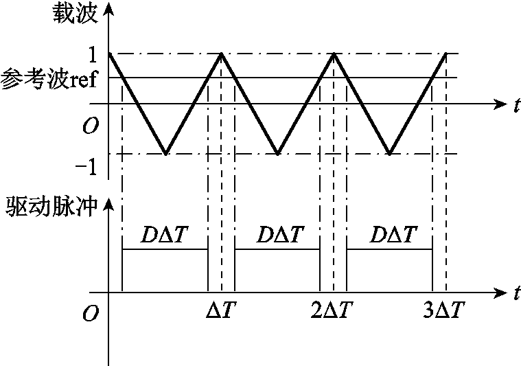
图6 PWM调制方式原理图
Fig.6 Schematic diagram of PWM modulation mode
参照文献[16]的电流重构算法和本文FTPM-RDM的A、B、C、D、E、F六相绕组相位依次相差60°的结构特点,将A相绕组故障电流进行重新分配,可获得A相绕组故障容错方案。A相开路容错方式为将A相绕组缺失的电流平均分成3份,由C、E两相绕组共同补偿1/3,D相单独补偿1/3,B、F两相共同补偿1/3;A相短路容错方式和开路故障相同,但是除补偿A相缺失电流,还要对A相短路电流进行补偿。
在Matlab/Simulink中,搭建基于传统CHBPWM和预测占空比CHBPWM的FTPM-RDM控制系统仿真模型。对两种CHBPWM控制策略在一相开路前后及短路故障情况进行对比仿真验证,设定电机转速为300r/min,外加15N·m的负载转矩。并对两种CHBPWM控制策略无故障态的转速和负载变化情况进行对比仿真验证。为了验证预测占空比CHBPWM在实际低频下的控制效果,仿真模型的采样频率取10kHz,其中FTPM-RDM参数见表2。
表2 永磁容错轮缘推进电机主要参数
Tab.2 Main parameters of six-phase FTPM-RDM

参数数值 定子电阻R/Ω1.2 定子电感L/mH27.42 极对数np15 额定转矩T/(N·m)23.87 额定功率P/kW1.5 额定转速n/(r/min)600
为了量化比较两种控制策略的性能,定义电机转矩脉动为
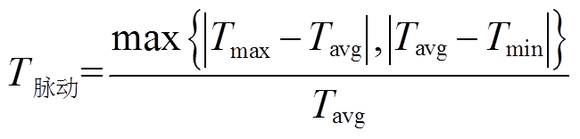 (10)
(10)
当电机无故障稳定运行时,在0.3s时A相发生开路故障同时对电机施加容错控制策略。传统CHBPWM和预测占空比CHBPWM的仿真结果分别如图7、图8所示。
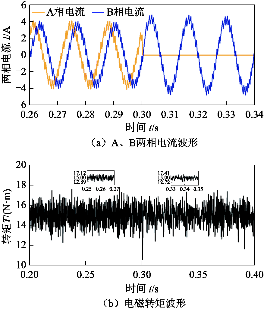
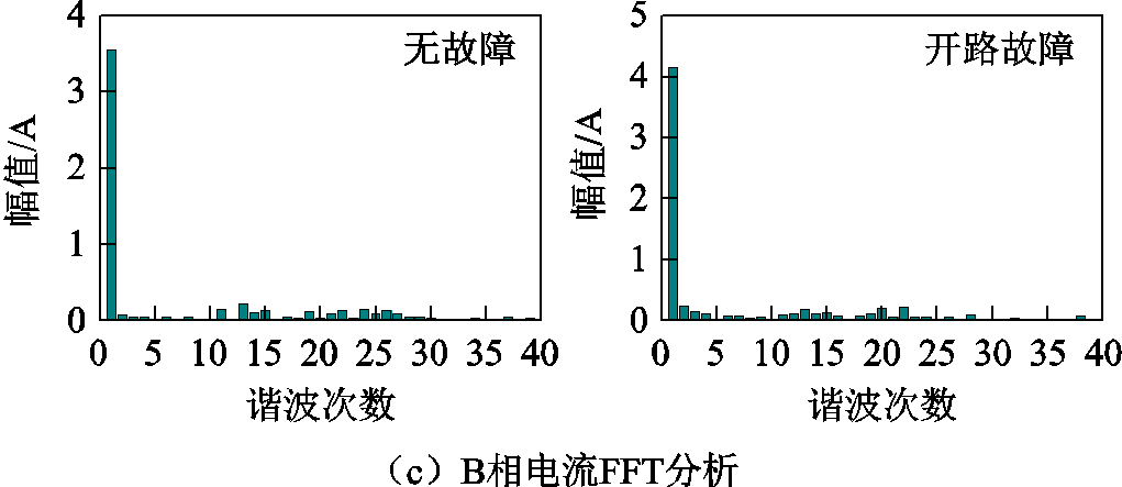
图7 开路前后传统CHBPWM仿真结果
Fig.7 Simulation results with traditional CHBPWM before and after open circuit fault
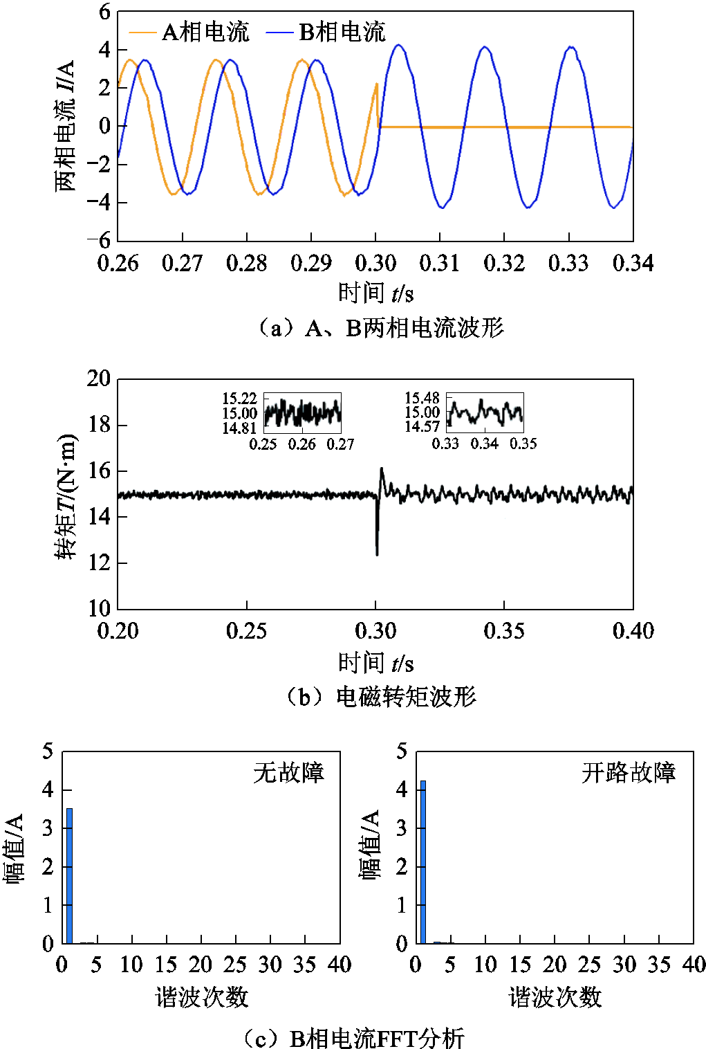
图8 开路前后预测占空比CHBPWM仿真结果
Fig.8 Simulation results with predictive duty cycle CHBPWM before and after open circuit fault
通过对比图7、图8波形可知:
1)无故障情况下:预测占空比CHBPWM的转矩脉动为1.47%,B相电流谐波含量较少,电流脉动较小;传统CHBPWM的转矩脉动为14.13%,B相电流谐波含量较多,电流脉动较大。
2)开路故障情况下:预测占空比CHBPWM的转矩脉动为3.20%,B相电流谐波含量较少,电流脉动较小;传统CHBPWM的转矩脉为16.07%,B相电流谐波含量较多,电流脉动较大。
仿真结果表明:无故障和开路故障情况下,预测占空比CHBPWM控制策略的转矩脉动、电流谐波畸变程度及电流脉动均明显小于传统CHBPWM控制策略。
电机无故障稳定运行,在0.3s时A相发生短路故障并施加容错控制策略。两种控制策略的仿真结果分别如图9、图10所示。
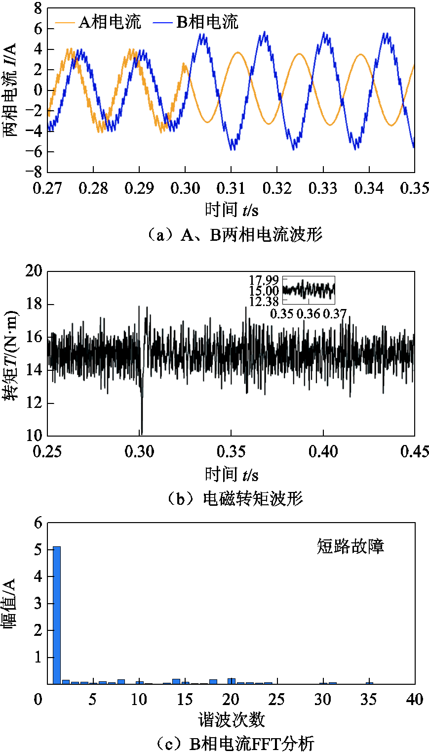
图9 短路前后传统CHBPWM仿真结果
Fig.9 Simulation results with traditional CHBPWM before and after short circuit fault
通过对比图9、图10可知:短路故障情况下,预测占空比CHBPWM控制策略的电流谐波及脉动情况明显小于传统CHBPWM控制策略。前者的转矩脉动为5.40%,而后者的转矩脉动为19.93%。因此,短路故障状态下,本文提出的预测占空比CHBPWM控制策略优于传统的CHBPWM控制策略。
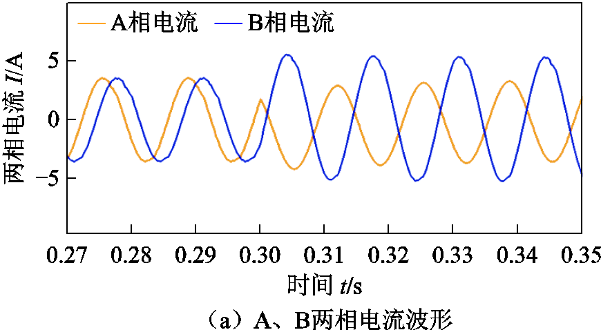
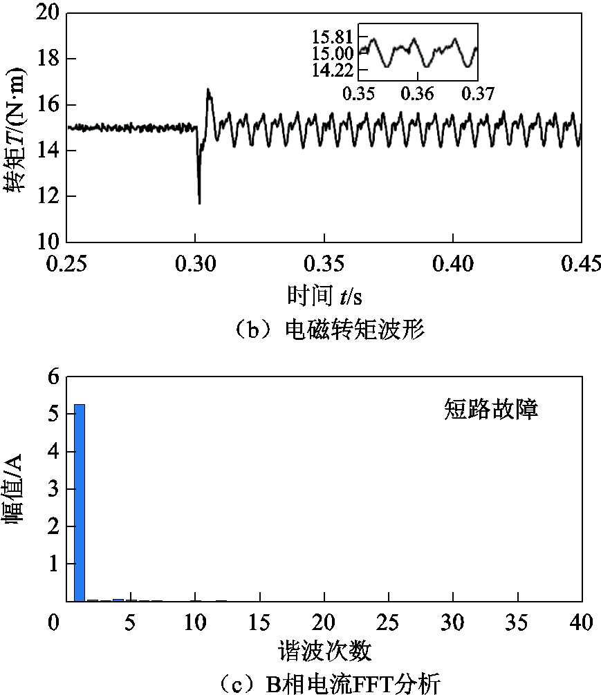
图10 短路前后预测占空比CHBPWM仿真结果
Fig.10 Simulation results with predictive duty cycle CHBPWM before and after short circuit fault
为进一步验证预测占空比CHBPWM控制策略的控制效果,在电机无故障状态下对两种CHBPWM控制策略在不同转速、负载情况的转矩脉动进行仿真对比,仿真结果见表3。
表3 不同转速、负载情况的转矩脉动对比
Tab.3 Torque pulsation comparison under different speed and load conditions
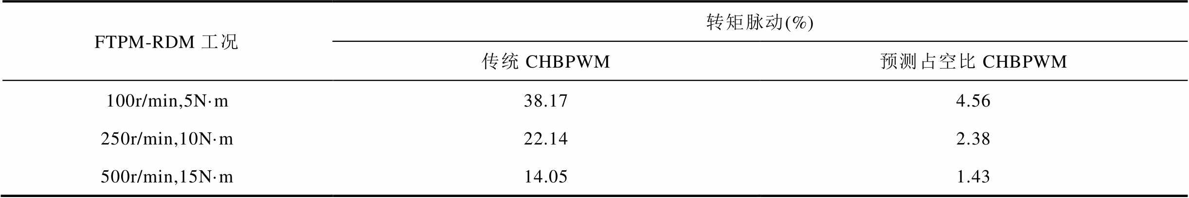
FTPM-RDM工况转矩脉动(%) 传统CHBPWM预测占空比CHBPWM 100r/min,5N·m38.174.56 250r/min,10N·m22.142.38 500r/min,15N·m14.051.43
仿真结果表明:无故障情况下,两种控制策略均能响应转速负载变化情况,预测占空比CHBPWM控制策略的转矩脉动明显小于传统CHBPWM控制策略。
为进一步验证预测占空比CHBPWM控制策略的优越性,搭建如图11所示的六相永磁容错轮缘推进电机实验平台。电机参数和仿真参数一致,控制器采用上海远宽能源科技有限公司研发的StarSim快速控制原型,该控制器可以将Simulink编写的控制算法下载到实时快速控制原型硬件中,实现对电机的快速精确控制[17]。为保证实验效果和仿真一致,采样频率设定为10kHz。
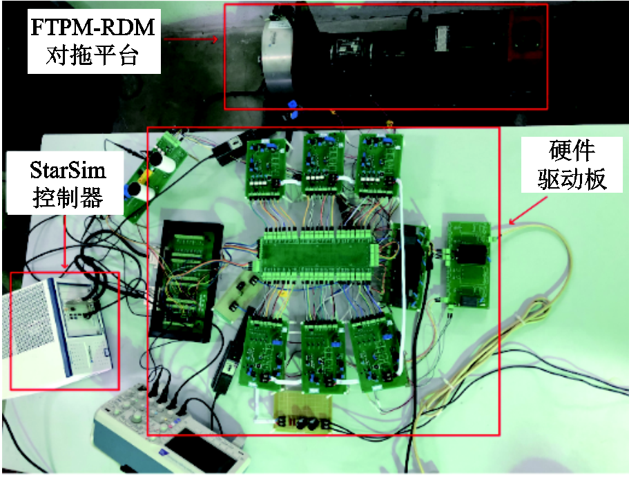
图11 六相永磁容错轮缘推进电机实验平台
Fig.11 Experimental platform of six phase FTPM-RDM
给定电机转速为200r/min,负载转矩为7N·m,电机稳定运行后,某一时刻发生一相开路故障并立即启动容错控制策略,电机电流、转矩对比响应曲线如图12、图13所示。
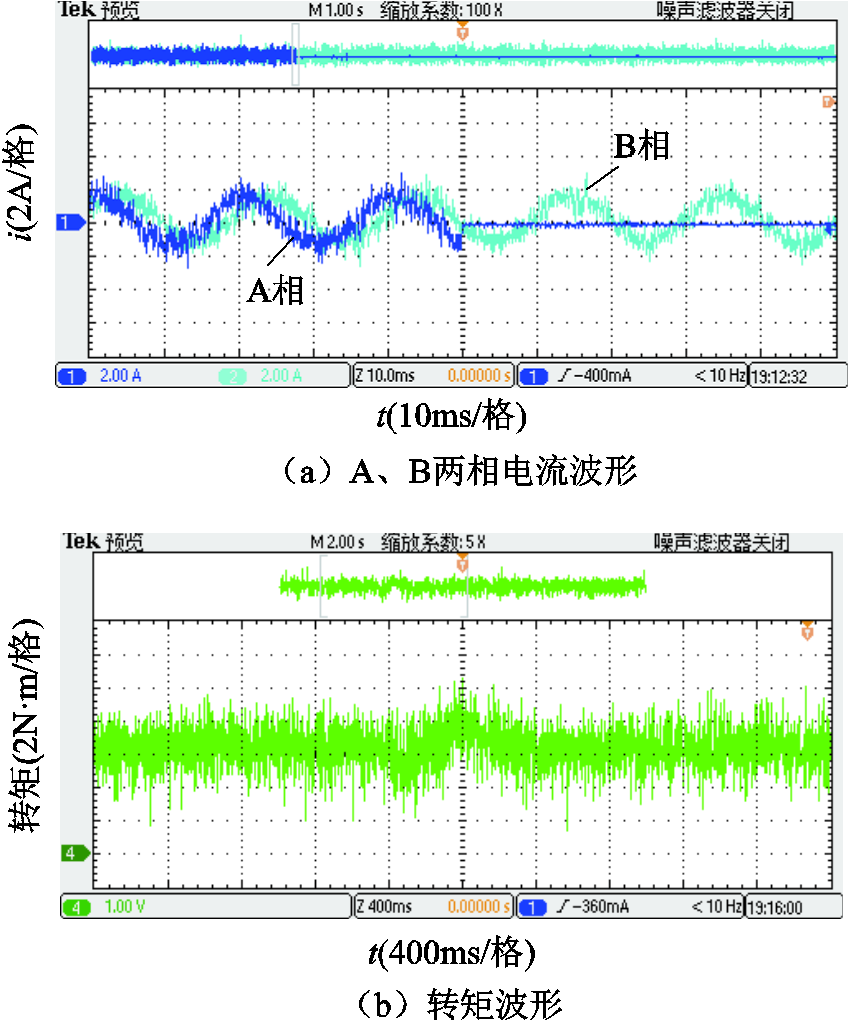
图12 开路前后传统CHBPWM实验结果
Fig.12 Experimental results with traditional CHBPWM before and after open circuit fault
对比图12、图13实验结果可知,开路故障前后采用预测占空比CHBPWM控制得到的实测电流波形和转矩波形比传统CHBPWM控制得到的波形精度更高。前者的电流脉动和畸变程度明显小于后者;前者的转矩脉动为17.14%,而后者的转矩脉动为28.57%,前者的转矩脉动明显小于后者。实验结果表明开路故障前后预测占空比CHBPWM控制策略的性能更好,进一步验证了该控制策略的有效性。
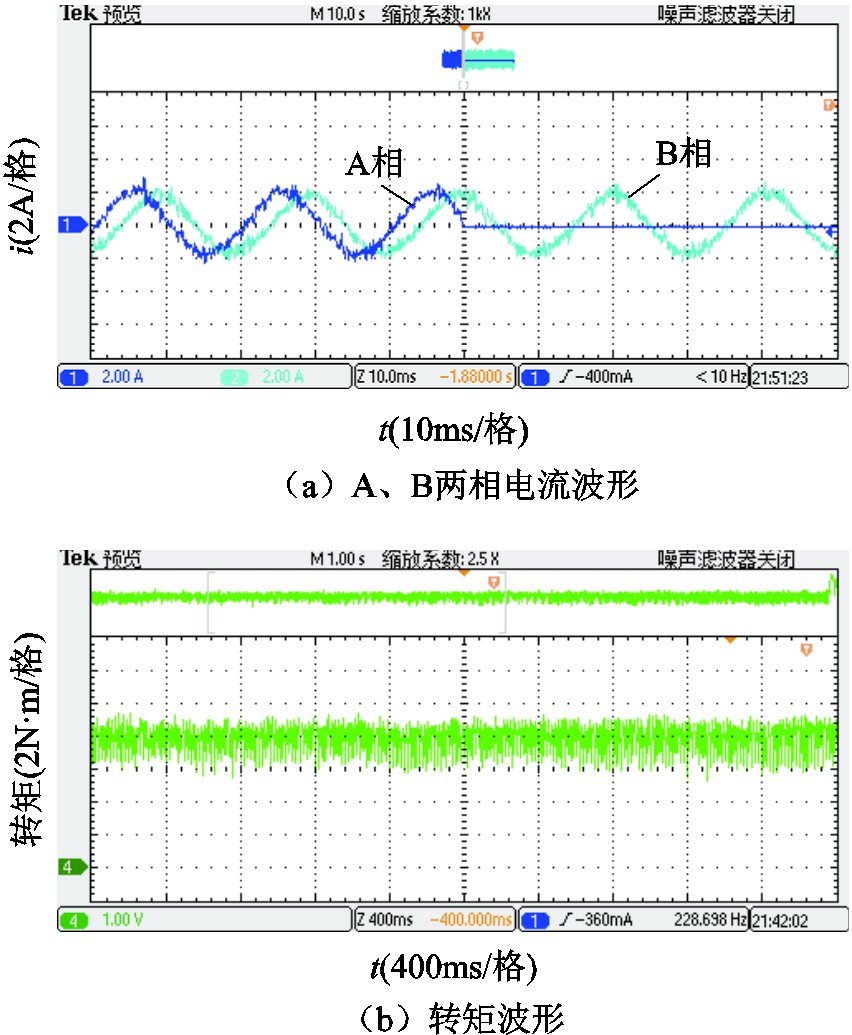
图13 开路前后预测占空比CHBPWM实验结果
Fig.13 Experimental results with predictive duty cycle CHBPWM before and after open circuit fault
电机给定转速为200r/min,给定负载转矩为7N·m,电机稳定后,某一时刻发生一相短路故障并立即启动容错控制策略,电机再次稳定后两种控制策略的实验结果分别如图14、图15所示。
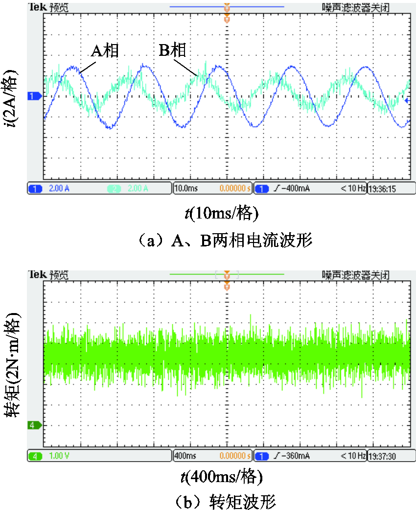
图14 短路故障下传统CHBPWM实验结果
Fig.14 Experimental results with traditional CHBPWM under short circuit fault condition
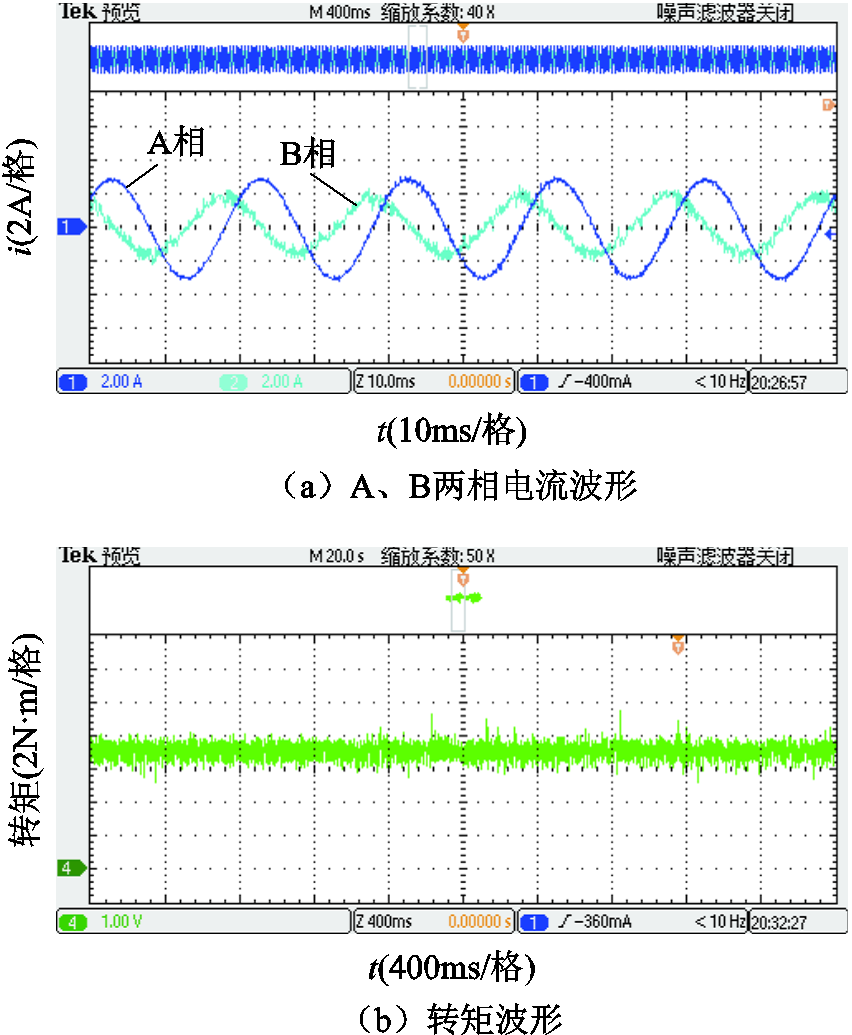
图15 短路故障下预测占空比CHBPWM实验结果
Fig.15 Experimental results with predictive duty cycle CHBPWM under short circuit fault condition
对比图14、图15的实验结果可知,在短路故障下,采用预测占空比CHBPWM控制策略得到的实测电流和转矩波形比传统CHBPWM策略所得的波形效果更好。前者的电流脉动和畸变率明显小于后者;前者的转矩脉动为22.86%,后者的转矩脉动为42.86%,前者的转矩脉动明显小于后者。实验结果表明短路故障下预测占空比CHBPWM控制策略的控制性能优于传统CHBPWM控制算法,进一步验证了该控制算法的正确性。
本文基于FTPM-RDM独特的H桥驱动电路结构特性,提出了一种预测占空比CHBPWM控制算法。仿真和实验结果证明,电机处在无故障、一相开路和短路故障状态下,本文提出的预测占空比CHBPWM控制算法在抑制转矩脉动、降低电流脉动和谐波畸变等方面都具有良好的效果,解决了传统CHBPWM固有的开关频率不固定、固定采样频率下控制精度低的问题,同时保留了CHBPWM算法简单、系统响应快的优点。为永磁容错轮缘推进电机提供了一个实际可行的控制方案。
参考文献
[1] 杨植, 严新平, 欧阳武, 等. 船舶轮缘推进装置驱动电机及控制方法研究进展[J]. 电工技术学报, 2022, 37(12): 2949-2960.
Yang Zhi, Yan Xinping, Ouyang Wu, et al. A Review of electric motor and control technology for rim-driven thruster[J]. Transactions of China Electrotechnical Society, 2022, 37(12): 2949-2960..
[2] Ojaghlu P, Vahedi A. Specification and design of ring winding axial flux motor for rim-driven thruster of ship electric propulsion[J]. IEEE Transactions on Vehicular Technology, 2019, 68(2): 1318-1326.
[3] Hassannia A, Darabi A. Design and performance analysis of superconducting rim-driven synchronous motors for marine propulsion[J]. IEEE Transactions on Applied Superconductivity, 2014, 24(1): 40-46.
[4] 陈文汉, 孙丹, 王铭泽. 断相故障下开绕组永磁同步电机模型预测控制容错控制策略研究[J]. 电工技术学报, 2021, 36(1): 77-86.
Chen Wenhan, Sun Dan, Wang Mingze. Research on fault-tolerance strategy based on model predictive control for open-winding PMSM system under open-phase fault[J]. Transactions of China Electrotechnical Society, 2021, 36(1): 77-86.
[5] Ma Rui, Zhu Jingwei, Lin Qianhong, et al. Influence of winding distribution on fault tolerant performance in a fault-tolerant permanent magnet rim driven motor[J]. IEEE Access, 2019, 7: 183236-183244.
[6] 赵凯辉, 周瑞睿, 冷傲杰, 等. 一种永磁同步电机的有限集无模型容错预测控制算法[J]. 电工技术学报, 2021, 36(1): 27-38.
Zhao Kaihui, Zhou Ruirui, Leng Aojie, et al. Finite control set model-free fault-tolerant predictive control for permanent magnet synchronous motor[J]. Transactions of China Electrotechnical Society, 2021, 36(1): 27-38.
[7] Niu Feng, Chen Xi, Huang Shaopo, et al. Model predictive current control with adaptive-adjusting timescales for PMSMs[J]. CES Transactions on Electrical Machines and Systems, 2021, 5(2): 108-117.
[8] Kapat S. Parameter-insensitive mixed-signal hysteresis-band current control for point-of-load converters with fixed frequency and robust stability[J]. IEEE Transactions on Power Electronics, 2017, 32(7): 5760-5770.
[9] Lin Xiaogang, Huang Wenxin, Wang Le. SVPWM strategy based on the hysteresis controller of zero-sequence current for three-phase open-end winding PMSM[J]. IEEE Transactions on Power Electronics, 2019, 34(4): 3474-3486.
[10] Jayaprakasan S, Ashok S, Ramchand R. Current error space vector based hysteresis controller for VSI fed PMSM drive[J]. IEEE Transactions on Power Electronics, 2020, 35(10): 10690-10699.
[11] 叶满园, 任威, 李宋, 等. 基于控制载波自由度的级联H桥逆变器改进型PWM技术[J]. 电工技术学报, 2021, 36(14): 3010-3021.
Ye Manyuan, Ren Wei, Li Song, et al. Improved PWM technology of cascaded H-bridge inverter based on control of carrier degree of freedom[J]. Transactions of China Electrotechnical Society, 2021, 36(14): 3010-3021.
[12] Zhu Jingwei, Bai Hongfen, Wang Xia, et al. Current vector control strategy in a dual-winding fault-tolerant permanent magnet motor drive[J]. IEEE Transactions on Energy Conversion, 2018, 33(4): 2191-2199.
[13] 李国华, 刘春武, 汪玉凤. 单相逆变器随机PWM选择性消谐滞环随机扩频方法[J]. 电工技术学报, 2021(6): 1279-1289.
Li Guohua, Liu Chunwu, Wang Yufeng. A novel hysteresis random spread-spectrum method in random PWM selective harmonic elimination for single-phase inverter[J]. Transactions of China Electrotechnical Society, 2021(6): 1279-1289.
[14] 廖金国, 花为, 程明, 等. 一种永磁同步电机变占空比电流滞环控制策略[J]. 中国电机工程学报, 2015, 35(18): 4762-4770.
Liao Jinguo, Hua Wei, Cheng Ming, et al. A variable-duty-cycle current-hysteresis control strategy for permanent magnet synchronous motors[J]. Proceedings of the CSEE, 2015, 35(18): 4762-4770.
[15] Jiang Xuefeng, Wang Shaoshuai, Li Qiang, et al. Design and optimization of dual-winding fault-tolerant permanent magnet motor[J]. CES Transactions on Electrical Machines and Systems, 2019, 3(1): 45-53.
[16] 李小庆, 朱景伟, 孙军浩, 等. 双绕组永磁容错电机矢量控制系统研究[J]. 电工技术学报, 2016, 31(5): 26-34.
Li Xiaoqing, Zhu Jingwei, Sun Junhao, et al. Study on the vector control system for dual winding fault-tolerant permanent magnet motors[J]. Transactions of China Electrotechnical Society, 2016, 31(5): 26-34.
[17] Liu Chaonan, Pan Zhiyuan, Wang Jinliang, et al. Development of distributed photovoltaic grid-connected simulation system based on StarSim platform[C]//2020 IEEE 3rd Student Conference on Electrical Machines and Systems (SCEMS), Jinan, China, 2021: 843-846.
Abstract The application of fault-tolerant permanent magnet rim drive motor (FTPM-RDM) in the rim-driven thruster (RDT) can improve the space utilization and efficiency of the ship, and significantly improve the reliability of the propulsion system. In recent years, scholars have proposed direct torque control, model predictive current control and other control algorithms for FTPM-RDM, but there are problems such as complex algorithm and slow response speed. With the traditional current hysteresis band pulse width modulation (CHBPWM) control strategy, each phase winding of FTPM-RDM can be controlled separately, which has the advantages of simple algorithm and fast fault tolerant control of open-circuit and short-circuit fault. However, due to the limitation of the operation speed of the digital controller and the switching frequency allowed by the power devices, the traditional CHBPWM control strategy has the disadvantages of large current ripple and high distortion rate, resulting in large torque ripple. To solve this problem, this paper proposes a predictive duty cycle CHBPWM control strategy, which can effectively improve current control accuracy and reduce motor torque ripple while retaining the simplicity and fast response of traditional CHBPWM algorithm.
The FTPM-RDM predictive duty cycle CHBPWM control system is a dual closed-loop vector control method using an outer loop for speed and an inner loop for current. First, the error between the given speed and the actual speed is obtained through PI regulator and coordinate transformation to obtain the given value of each phase current in the static coordinate system. Then, the predicted current hysteresis width of each phase winding in the next cycle is obtained through the rotor position, electrical angular velocity and DC bus voltage of the motor at the current moment. Then, the predicted duty cycle of each phase is obtained according to the actual current relative hysteresis position to achieve the closed-loop control of the motor. At the same time, combined with fault-tolerant control strategy, one phase open and short circuit fault tolerant control of motor can be realized. This method optimizes the traditional CHBPWM control by predicting the current hysteresis width and duty cycle of a single sampling period in real time, effectively improving the control accuracy of motor phase current.
Comparing the simulation results of the two control strategies, the predicted duty cycle CHBPWM control strategy has significantly less current harmonics and pulsations than the traditional CHBPWM control strategy under the healthy, one phase open-circuit and short-circuit conditions. The torque ripple of the former is 1.47%, 3.20% and 5.40% respectively, while that of the latter is 14.13%, 16.07% and 19.93%. The torque ripple of the former is obviously smaller than that of the latter.
Comparing the experimental data of the two control strategies, the measured current waveform and torque waveform obtained by the predictive duty cycle CHBPWM control are more accurate than those obtained by the traditional CHBPWM control before and after the open-circuit fault and under the condition of one phase short-circuit fault. The current ripple and distortion degree of the former are obviously smaller than those of the latter. The torque ripple of the former is 17.14%, 22.86% respectively, and the torque ripple of the latter is 28.57%, 42.86%, The torque ripple of the former is obviously smaller than that of the latter.
The simulation and experimental results show that the predictive duty cycle CHBPWM control algorithm has a good effect in restraining the torque ripple, reducing the current ripple and harmonic distortion of the motor under the same working conditions, whether the motor is in the healthy, one phase open-circuit or short-circuit fault conditions, and solves the problem that the switching frequency of the traditional CHBPWM control algorithm is not fixed, and the control accuracy is low under the fixed sampling frequency, while retaining the advantages of the CHBPWM algorithm's simplicity and fast system response.
Keywords:Fault-tolerant permanent magnet rim drive motor, H-bridge inverter circuit, predictive duty cycle, StarSim
DOI:10.19595/j.cnki.1000-6753.tces.211251
中图分类号:TM351
国家自然科学基金(51777024)和辽宁省自然科学基金(2020-MS-129)资助项目。
收稿日期 2021-08-11
改稿日期 2021-11-29
王志彬 男,1997年生,硕士研究生,研究方向为永磁容错电机控制技术、新型电机驱动技术等。E-mail:2830791818@qq.com
朱景伟 男,1964年生,教授,博士生导师,研究方向为永磁容错电机设计及其控制技术、电力电子变换技术等。E-mail:zjwdl@dlmu.edu.cn(通信作者)
(编辑 赫蕾)