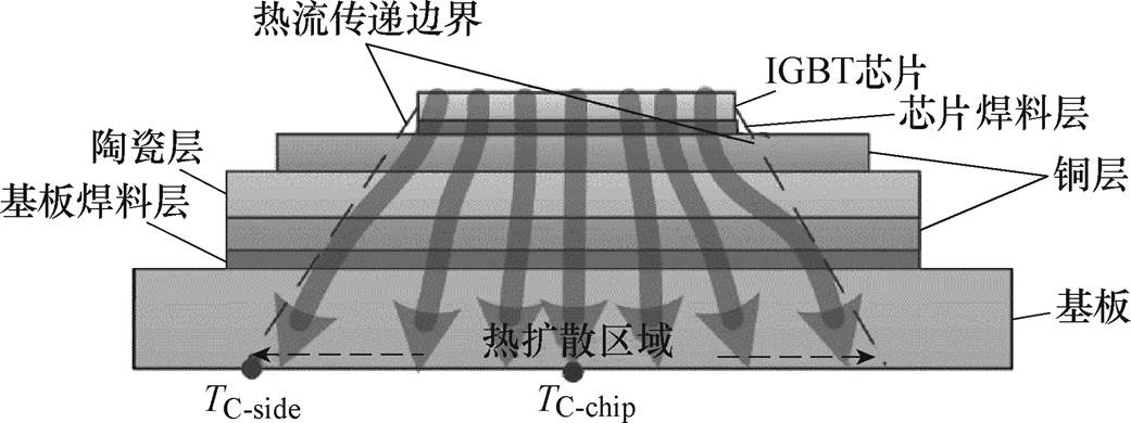
图1 健康功率器件内部热流分布
Fig.1 The heat flow in an healthy device
摘要 功率器件的焊料层易受到温度波动逐步发生老化脱落,造成热量无法快速消散而在芯片处积聚,引起芯片过热损毁,造成功率器件突发失效,因此,焊料层老化的实时评估是实现功率器件可靠运行的重要保障。该文通过提出基于壳温的焊料层老化评估方法,分析了焊料层老化影响的壳温分布情况,建立了基于壳温的基板二维温度梯度模型对壳温分布变化规律,研究了壳温分布变化与热阻抗的关联情况,以焊料层老化程度作为中间变量,通过离线加速老化平台采集壳温分布和热阻抗的演化信息,建立基板二维温度梯度与热阻抗关系的数据库,在工程应用中,通过布设在器件基板和散热板之间的传感器测量壳温并计算二维温度梯度,通过数据库识别热阻抗值对器件可靠性进行评估。在仿真和实验的老化分析中,表征壳温分布的二维温度与热阻抗的变化趋势相同,当器件失效时,二维温度梯度和热阻抗分别增长了16.1%、20%和20.1%,表明二维温度梯度与热阻抗受焊料层老化影响是一致的,与现有的方法相比,该方法通过壳温便可实现功率器件的可靠性评估。
关键词:功率器件 焊料层老化 可靠性 温度梯度
焊料层脱落是功率器件最重要的失效形式之一,作为层状叠加结构的功率器件,在运行过程中,由于各层材料的热膨胀系数差异以及温度分布的不均而产生热-机械应力[1-3]。热-机械应力的持续作用将造成焊料层产生裂纹或空洞等材料缺陷,从而降低焊料层传递热量的有效面积,功率器件内部热传递阻抗增加,热量在器件芯片处聚集等,造成芯片极度温升使其无法正常工作,甚至造成损毁[4-7]。基于此,开展焊料层老化状态的评估研究对功率器件可靠性评估具有一定的指导意义[8-11]。
近年来,国内外专家学者对功率器件焊料层老化状态进行了评估研究。目前,焊料层老化状态的评估方法包括电参数法和热参数法。电参数法通过监测某些与器件老化程度相关的电特性参数的变化实现器件健康状态的评估[12-14]。文献[14]提出了基于功率变换器谐波电流的器件焊料层老化评估模型,由于电参数法对信号采集电路的动态响应速度及测量精度要求较高,需要设计专门的信号采集电路,增加了电路的复杂程度,引起功率器件新的可靠性问题。
与电参数法相比,热参数法无须设计专门的测量电路、且适用于任何封装类型的模块,实现简单、经济性好,在实际中应用十分广泛[15-18]。文献[15]提出了通过器件壳温和散热板温度差值DTca的变化实现焊料层健康状态的评估,而DTca的变化受到器件功率损耗值的影响,须建立不同工作状态下功率损耗信息库,造成监测成本增加。为解决上述问题,文献[16]提出采用器件基板至散热板的热阻抗Rca对焊料层的老化程度进行评估,但Rca的数值还依赖导热脂和散热板的老化状态,使得焊料层状态评估的准确性降低。为优化此方法,文献[18]提出了基于器件基板温度梯度的焊料层状态评估模型,但此方法仅能实现焊料层某一方向上老化状态的定性判断。综上所述,如何实现功率器件焊料层老化状态评估的经济性和准确性还有许多问题需要研究。
本文提出了一种新型的基于壳温的功率器件可靠性评估方法,通过器件的壳温信息便可对焊料层的老化状态做出评估,利用焊料层评估结果对功率器件可靠性做出判断,与传统方法相比,该方法具有经济性好、准确性高的优点。
通常功率器件由多个IGBT芯片组成,IGBT芯片作为热源,是器件内部全部热量的来源。热量在IGBT芯片上表面产生,并向下扩散到基板,如图1所示。
图1 健康功率器件内部热流分布
Fig.1 The heat flow in an healthy device
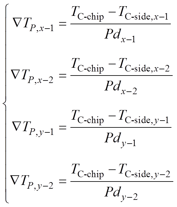
考虑到器件散热的热扩散角度,基板上的温度分布区域远大于芯片的温度分布区域。由于大部分热量沿最佳的热路径(即垂直方向)向下传播,因此基板底部表面的中心温度远高于其余区域,基板的温度分布可认为是非均匀的。基板温度分布的不均匀性程度可以用温度梯度ÑT的数值描述为
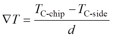 (1)
(1)
式中,TC-chip和TC-side分别为基板中心区域和边缘区域的壳温;d为选定两点间的距离。图1中TC-chip对焊料层老化造成的器件热路径的变化非常敏感,而TC-side位于焊料层老化的起始区域。
焊料层老化情况的出现表明焊料层内部已经产生了裂纹。裂纹使得器件内部的热传导区域收缩,老化功率器件内部热流分布如图2所示。通常,裂纹起源于焊料层的边缘区域,然后扩展到焊料层的中心区域,造成芯片处产生的热量只能通过焊料层中心的无裂纹区域扩散到基板。上述情况导致基板中心区域的温度不断上升,其余区域温度持续下降。最终,基板温度分布的不均匀性进一步增强。描述温度分布不均匀性的ÑT值随着焊料老化而增大。因此,ÑT可以用来监测焊料老化过程。
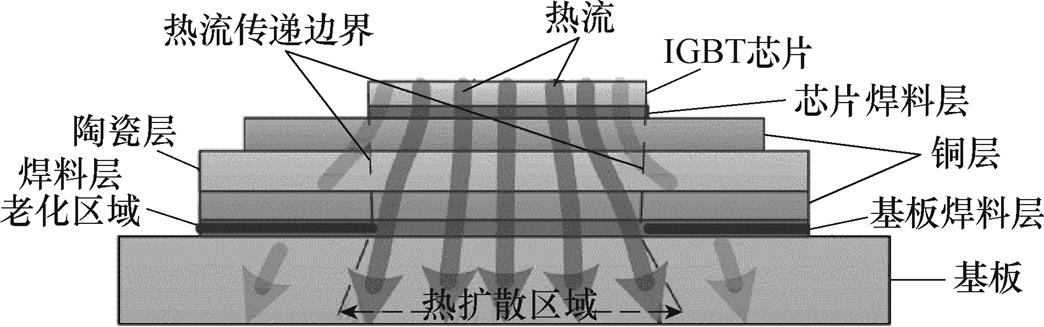
图2 老化功率器件内部热流分布
Fig.2 The heat flow in an aging device
此外,为消除器件的功率损耗对ÑT数值的影响,可将ÑT的数值按功率损耗归一化为ÑTP,即
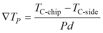 (2)
(2)
式中,P为器件的功率损耗。
在实际应用中,焊料层裂纹的形成是十分复杂的。虽然裂纹通常从焊料层的边缘开始形成,然后扩展到焊料层中心,但裂纹形成的位置是不确定的。因此,ÑTP无法充分评价裂纹对焊料层老化的影响。为了更准确地表征焊料老化过程,可以从二维平面的两个方向,即图3所示的x和y方向,监测基板温度梯度的演变。两个主要方向又分为四个方向,即x-1,x-2,y-1和y-2。ÑTP,x-1、ÑTP,x-2、ÑTP,y-1、ÑTP,y-2分别为底板层四个不同方向的温度梯度,即
 (3)
(3)
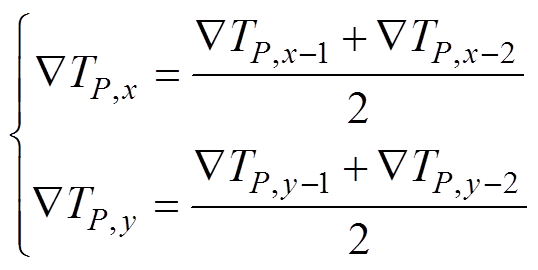
主方向的温度梯度分别为ÑTP,x和ÑTP,y,即
 (4)
(4)
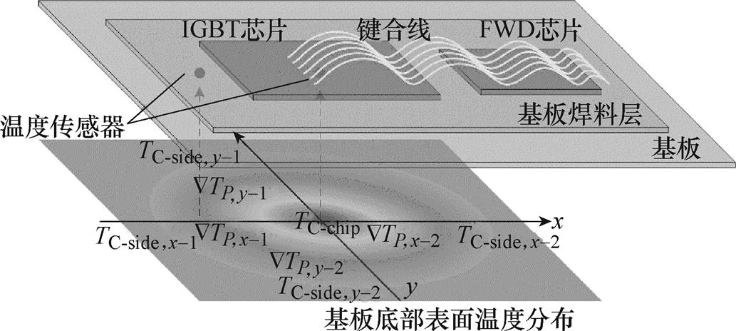
图3 基板底部表面温度监测分布图
Fig.3 Monitoring of case temperatures on the bottom surface of the baseplate layer
采用参数ÑTP,x和ÑTP,y,无论裂纹在焊料层哪个区域产生,都可以描述焊料层的老化程度。
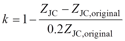
功率器件芯片至基板的热阻抗值ZJC是一个可以定量表征器件焊料层老化程度的参数,其依赖器件芯片处的温度,在实际应用中芯片温度的获取成本非常高。因此,以焊料老化程度为中间变量,通过离线加速老化试验,采集器件老化过程中的温度信息,采用式(3)和式(4)计算ÑTP,x和ÑTP,y,建立包含ÑTP,x、ÑTP,y与ZJC的数据库。在器件运行过程中,通过ÑTP,x和ÑTP,y的计算值,采用查表法即可获取ZJC数值,对器件的可靠性做出评价。表达式为
 (5)
(5)
式中,k为器件的健康可靠性;ZJC为器件实时的热阻抗值;ZJC,original为器件健康状态下的热阻抗值,ZJC增长达到20%是器件失效的标准[19-21]。基于计算的k值可实现器件可靠性的评估。
功率器件的老化试验昂贵且耗时。当器件的温度波动较低或器件的结温不超过阈值时,器件的热机械损伤非常小。从经济性角度出发,加速老化试验是评估器件可靠性的常用方法。加速老化试验采用过载直流或交流将器件加热至高温,然后关闭电源,采用外部冷却系统如空气强制对流或水冷系统使器件的温度快速下降。通过以上方法,器件会承受非常大的温度波动,使得器件的热-机械损伤快速增大。最终,器件的失效过程在很短的时间内即可完成。在加速老化测试中,器件的健康表征参数ÑTP,x、ÑTP,y与ZJC数值在运行固定功率循环次数(如200次功率循环)后被记录。功率器件加速老化测试直到器件失效时停止。因此,ÑTP,x、ÑTP,y与ZJC的数据库涵盖了功率器件的全生命周期。ÑTP,x、ÑTP,y与ZJC之间的关系就通过数据库构建完成了。由于两类参数之间的关系是非线性的,因此,无法采用数学方法进行描述。在实际运行中,根据ÑTP,x和ÑTP,y的计算信息,结合构建的数据库,可得到ZJC的值。与文献[12-13]中描述的方法相比,本文所提出的方法只依赖壳温,而壳温仅须基板和散热器之间的温度传感器即可获得,因此,在经济性方面更有优势。
本方法实现流程如图4所示。分为两个阶段实现:第一阶段,通过基板和散热板之间的温度传感器测量壳温,如图3所示,采用式(3)和式(4)对基板温度梯度ÑTP,x和ÑTP,y进行计算,并将计算值与健康器件的基板温度梯度进行对比,判断器件焊料层是否发生了老化;第二阶段,根据离线功率循环试验建立的ÑTP,x、ÑTP,y与ZJC的数据库获取器件老化的ZJC,基于ZJC数值采用式(5)对器件的可靠性进行评估。
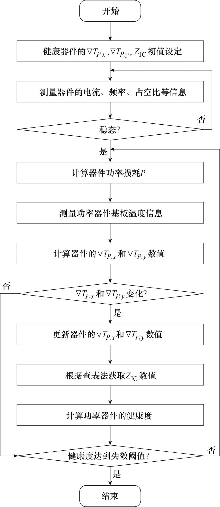
图4 方法实现流程
Fig.4 The flow chart of the proposed method
通过有限元分析(Finite Element Analysis, FEA)实例对提出方法的有效性进行验证。首先采用Pro/ENGINEER对SEMIKRON商用功率器件(SKM75GB123D)进行三维建模,并将三维模型导入Ansys软件中进行有限元分析,如图5所示。功率器件的工作条件如下:直流电压VDC=1 000 V,负载电流IC=60 A,开关频率fsw=10 kHz,调制指数M=1,功率因数PF=0.8,线路频率f0=50 Hz。
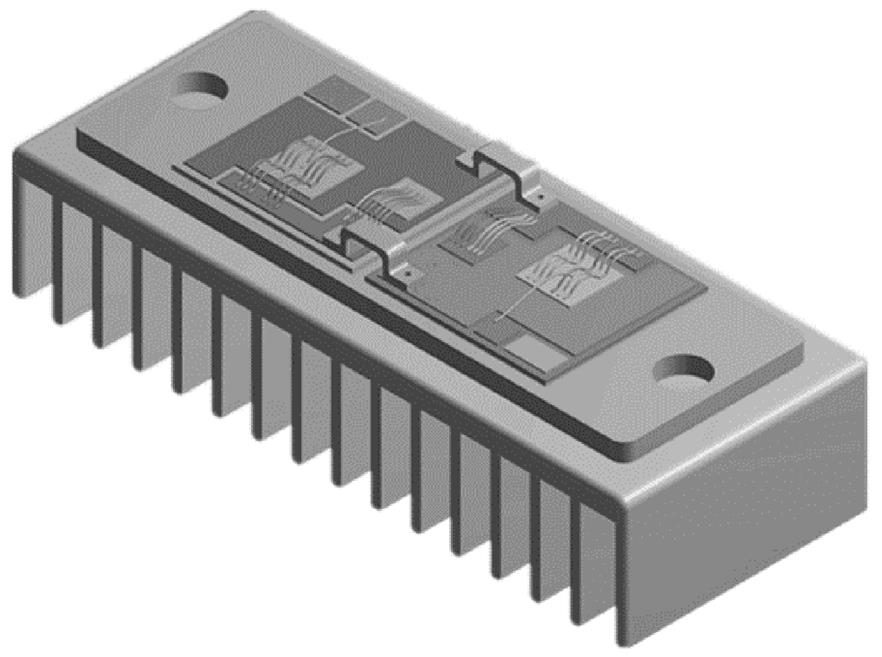
图5 功率器件三维模型
Fig.5 3-D model of the power device
为深入分析焊料层老化对功率器件热特性的影响,通过以下六个老化场景来模拟焊料层老化的演变过程设计:①健康状况;②焊料层出现0.5 mm裂纹的轻微老化状态;③焊料层出现1.0 mm裂纹的轻度老化状态;④焊料层出现1.5 mm裂纹的中等老化状态;⑤焊料层出现2.0 mm裂纹的重度老化状态;⑥焊料层出现2.5 mm裂纹的危险老化状态。六种焊料层的老化状态的示意图如图6所示。
考虑器件的工作条件,计算器件的功率损耗并将其加载到各老化状态的器件芯片上,采用Ansys软件进行瞬态热分析。其中健康功率器件剖面的温度分布云图如图7所示。由图7可知,热量生成处的芯片温度最高,随着与芯片距离的增大,温度逐渐降低。芯片处的热量向下扩散的角度约为45℃,经过各层结构的传递后,器件基板的温度区域远大于芯片处的温度区域。
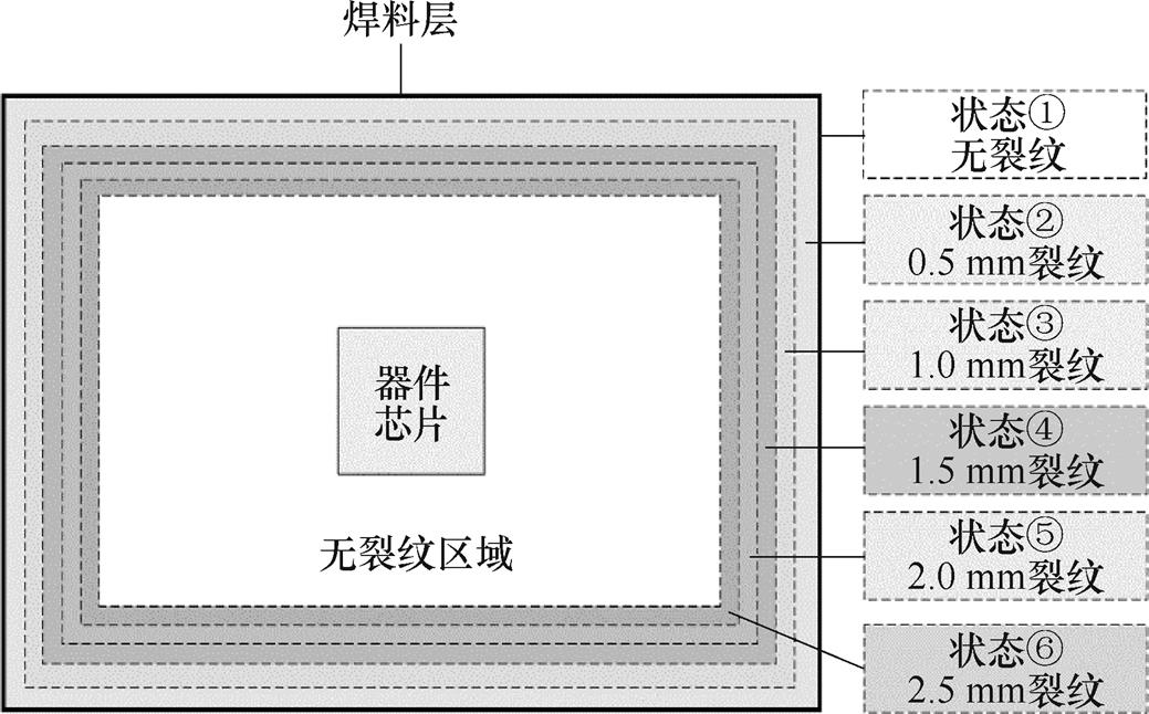
图6 功率器件焊料层老化设计示意图
Fig.6 The schematic of the design solder aging conditions
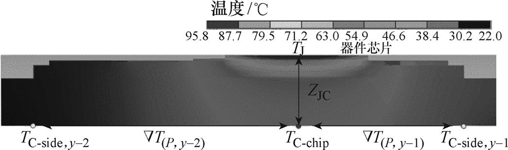
图7 健康功率器件剖面温度分布云图
Fig.7 The temperature distribution of cross plane
老化状态①和老化状态⑥的功率器件的热流分布如图8所示。与健康功率器件相比,老化器件中的大部分热量只能通过未老化的焊料层区域向基板层扩散,造成基板层涵盖的温度区域变小。由于器件内部的热量集中在基板层的中心区域,基板层中心区域的温度不断升高,而剩余区域的温度不断降低。因此,依赖基板层壳温的ÑTP,x和ÑTP,y的值会发生变化。连续记录六种老化情形下器件壳温的演化,并采用式(3)和式(4)估算ÑTP,x和ÑTP,y的数值。表征焊料老化的热阻抗ZJC为
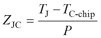 (6)
(6)
式中,TJ为器件芯片的结温。在瞬态热分析过程中分别记录不同老化状态器件的TJ值,代入式(6)中可得ZJC。经计算得到的ÑTP,x、ÑTP,y与ZJC的数值如图9所示。
由图9可知,ÑTP,x、ÑTP,y与ZJC随焊料老化进程而不断增大。当焊料层裂纹达到2.5 mm时,与健康的器件相比,ÑTP,x增大约10.3%,ÑTP,y增大约15.4%,ZJC增大约15.2%。这表明ÑTP,x、ÑTP,y与ZJC的值与焊料层的老化程度有关。由于焊料层的老化程度是唯一的,因此,ÑTP,x、ÑTP,y与ZJC之间的关系是唯一的。此外,ÑTP,x和ÑTP,y可描述任意位置的焊料层老化情况。
在工程应用中,采集器件的壳温信息计算ÑTP,x、ÑTP,y的数值,基于包含ÑTP,x、ÑTP,y与ZJC关系的数据库确定ZJC的值,代入式(6)中计算器件的可靠性。六种老化状态的功率器件的可靠性如图10所示。由图10可知,伴随焊料层老化程度的加剧,功率器件的可靠性逐渐降低。与传统的依赖器件结温的ZJC计算方法相比,本方法只需知道器件壳温信息便可获取ZJC数值,进而评估器件的可靠性,在实际应用中实现简单、经济性好。
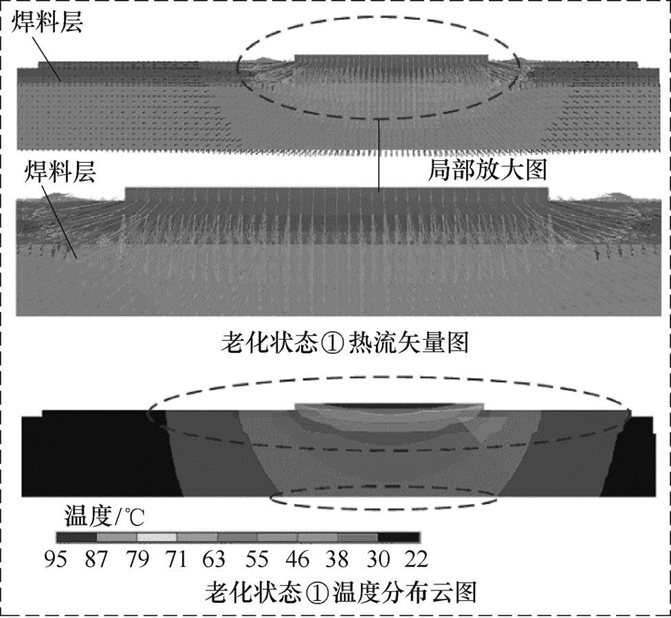
(a)老化状态①下热矢量图和温度分布图
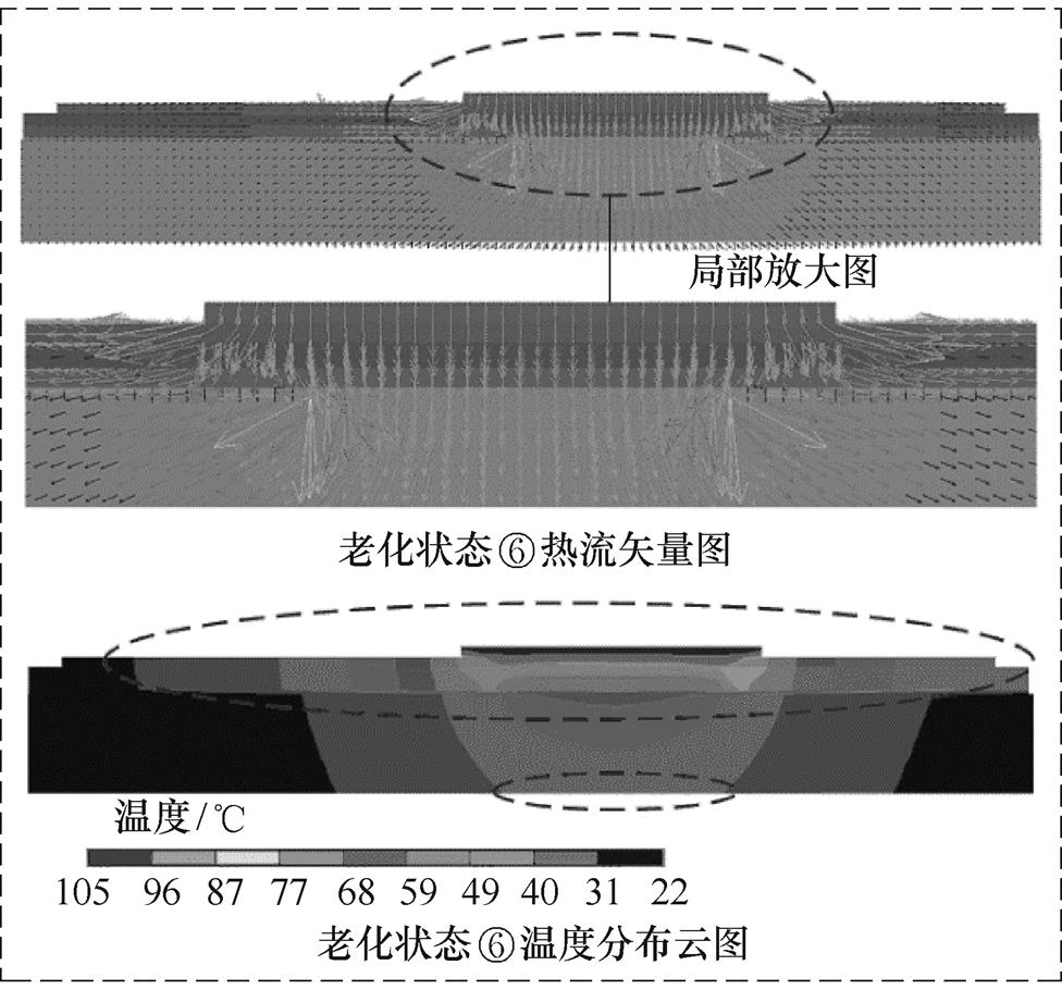
(b)老化状态⑥下热矢量图和温度分布图
图8 功率器件内部热流随焊料层老化的演化趋势
Fig.8 The evolution of heat flow during the solder aging process
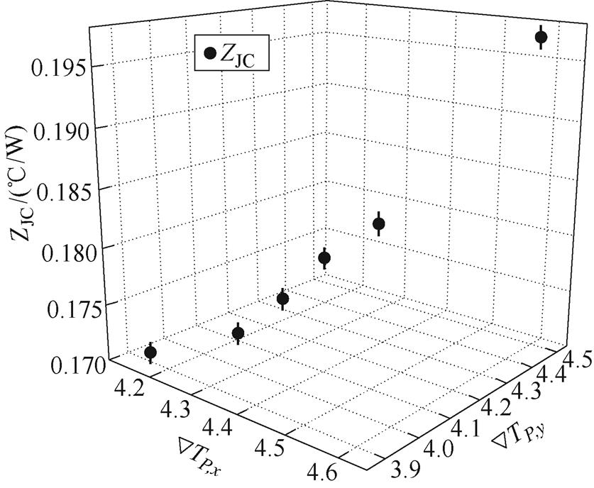
图9 焊料层老化过程中ÑTP,x、ÑTP,y与ZJC的演化趋势
Fig.9 The evolution of ÑTP,x, ÑTP,y and ZJC during the solder aging process
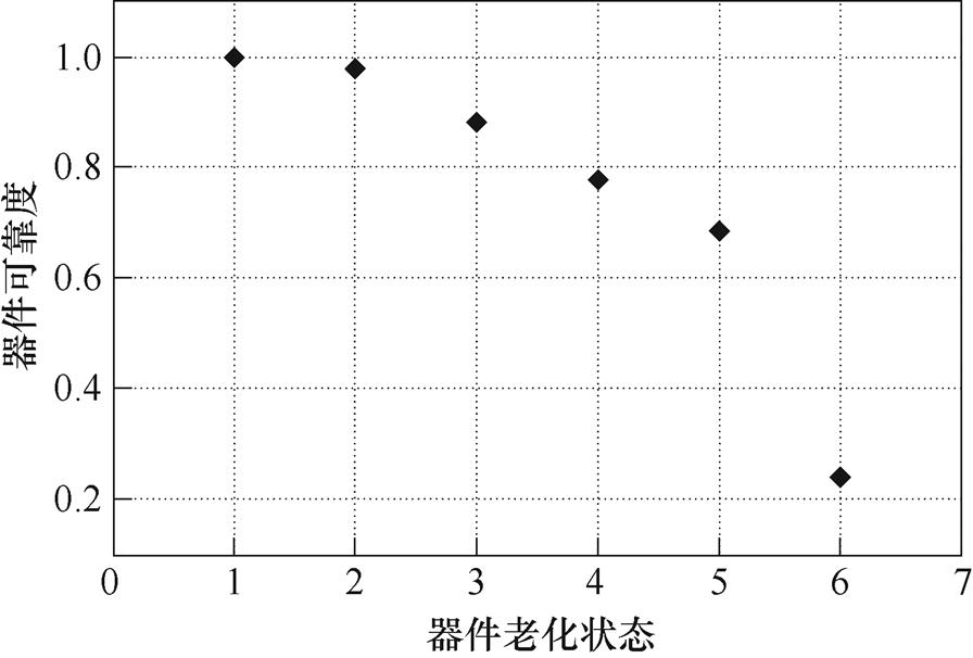
图10 器件可靠性的演化趋势
Fig.10 The evolution of the reliability for the device
实验配置如图11所示,由塞米控生产的功率器件(SKM75GB123D),获取温度信息的红外相机(红外相机型号为Fotric 288,采样频率为30 Hz),测量器件电信号的录波仪,功率器件驱动器,直流电源,铝制散热器以及LabVIEW数据采集系统等,其中铝制散热器上表面刻有用于安装热敏电阻的凹浅槽。
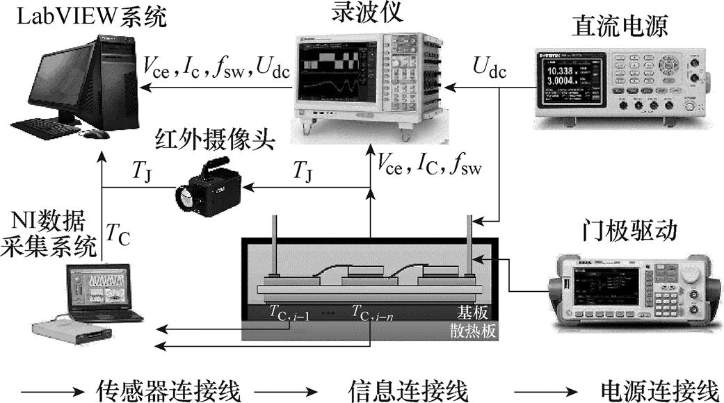
图11 实验设备示意图
Fig.11 The schematic diagram of experimental equipment
为快速获取功率器件老化过程中壳温演变信息,搭建器件加速老化测试平台,首先采用45 A的直流电流对功率器件持续加热至芯片结温达到150℃左右,然后断开直流电源采用强制风冷将芯片结温降至60℃。在一个循环周期内功率器件承受的温度冲击为90℃。采用LabVIEW系统持续采集器件壳温信息,并计算ÑTP,x和ÑTP,y的数值。此外,每200个循环周期中断一次加速老化测试,采用红外摄像头记录芯片结温信息,并代入式(6)计算ZJC数值。当ZJC增长达到20%时终止器件的加速老化测试。加速老化测试过程中ÑTP,x、ÑTP,y与ZJC的演化如图12所示。
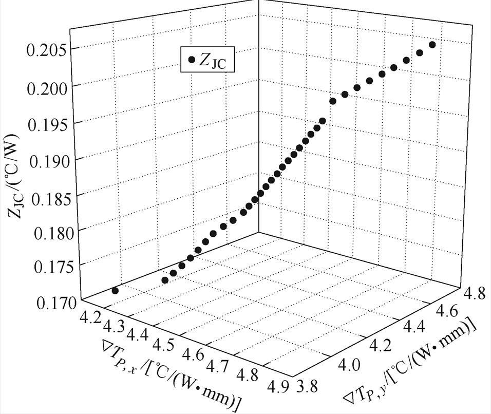
图12 焊料层老化过程中ÑTP,x、ÑTP,y与ZJC演化趋势
Fig.12 The evolution of ÑTP,x, ÑTP,y and ZJC during the solder aging process
由图12可以看出,ÑTP,x、ÑTP,y与ZJC随着加速老化试验的进行而持续增大。ÑTP,x、ÑTP,y与ZJC在测试结束时分别增加16.1%、20%和20.1%。上述结果表明,ÑTP,x、ÑTP,y与ZJC数值均依赖焊料层的老化程度。考虑到焊料层的老化程度是唯一的,因此ÑTP,x、ÑTP,y与ZJC之间的关系是唯一的,如图12所示。因此,在实际应用中,采集器件的壳温信息计算ÑTP,x、ÑTP,y的数值,基于包含ÑTP,x、ÑTP,y与ZJC关系的数据库确定ZJC的值,代入式(6)中计算器件的可靠度。加速老化测试期间功率器件的可靠度变化如图13所示。由图13可知,伴随焊料层老化程度的加剧,功率器件的可靠性逐渐降低。
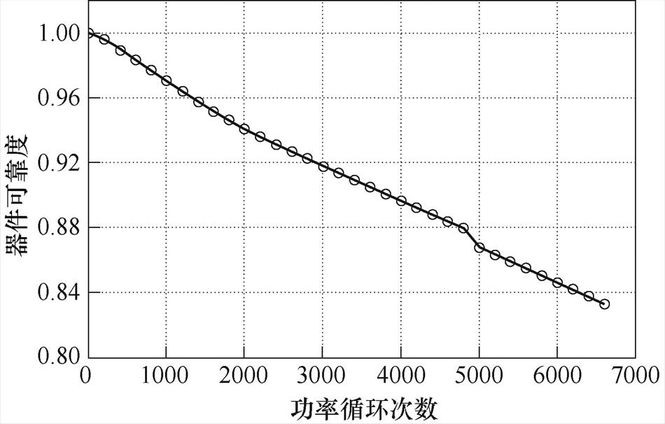
图13 器件可靠性随焊料层老化的演化趋势
Fig.13 The evolution of the reliability during the solder aging process
本文研究了焊料层老化对壳温分布的影响机制,有限元仿真结果表明了焊料层老化使得芯片热流向下传递的区域变窄,当老化区域达到2.5 mm时,焊料层的热传递区域减小近40%,热传递区域的变化使得基板中心处的温度不断升高,而基板边缘处的温度不断降低,最终导致基板壳温分布的变化。
此外,本文提出了二维温度梯度计算方法对基板壳温分布的变化进行描述。在仿真部分中,当老化区域达到2.5 mm时,二维温度梯度ÑTP,x和ÑTP,y分别增大了约10.3%、15.4%,而热阻抗ZJC增大约15.2%;在实验部分中,ÑTP,x、ÑTP,y与ZJC在加速老化测试结束时分别增加16.1%、20%和20.1%。上述结果表明,焊料层老化导致了基板壳温分布的变化,进而造成二维温度梯度的变化;同时二维温度梯度与热阻抗的变化保持一致。
因此,以焊料层老化程度作为中间变量,建立二维温度梯度与器件热阻抗关系的数据库。在现场应用中,通过布设在器件基板和散热板之间的温度传感器采集壳温,进而计算二维温度梯度数值,基于数据库识别的热阻抗值对器件可靠性进行评估,本文的研究方法对工程应用具有一定的指导作用。
参考文献
[1] Gong Xiang, Qiao Wei. Bearing fault diagnosis for direct-drive wind turbines via current-demodulated signals[J]. IEEE Transactions on Industrial Electro- nics, 2013, 60(8): 3419-3428.
[2] Ribrant J, Bertling L M. Survey of failures in wind power systems with focus on Swedish wind power plants during 1997-2005[J]. IEEE Transactions on Energy Conversion, 2007, 22(1): 167-173.
[3] Luo Haoze, Chen Yuxiang, Sun Pengfei, et al. Junction temperature extraction approach with turn- off delay time for high-voltage high-power IGBT modules[J]. IEEE Transactions on Power Electronics, 2016, 31(7): 5122-5132.
[4] Yang Shaoyong, Xiang Dawei, Bryant A, et al. Condition monitoring for device reliability in power electronic converters: a review[J]. IEEE Transactions on Power Electronics, 2010, 25(11): 2734-2752.
[5] 王学梅, 张波, 吴海平. 基于失效物理的功率器件疲劳失效机理[J]. 电工技术学报, 2019, 34(4): 717-727.
Wang Xuemei, Zhang Bo, Wu Haiping. A review of fatigue mechanism of power devices based on physics-of-failure[J]. Transactions of China Electro- technical Society, 2019, 34(4): 717-727.
[6] 姚芳, 胡洋, 李铮, 等. 基于结温监测的风电IGBT热安全性和寿命耗损研究[J]. 电工技术学报, 2018, 33(9): 2024-2033.
Yao Fang, Hu Yang, Li Zheng, et al. Study on thermal safety and lifetime consumption of IGBT in wind power converters based on junction temperature monitoring[J]. Transactions of China Electrotechnical Society, 2018, 33(9): 2024-2033.
[7] Smet V, Forest F, Huselstein J J, et al. Ageing and failure modes of IGBT modules in high-temperature power cycling[J]. IEEE Transactions on Industrial Electronics, 2011, 58(10): 4931-4941.
[8] 王莉娜, 邓洁, 杨军一, 等. Si和SiC功率器件结温提取技术现状及展望[J]. 电工技术学报, 2019, 34(4): 703-716.
Wang Lina, Deng Jie, Yang Junyi, et al. Junction temperature extraction methods for Si and SiC power devices-a review and possible alternatives[J]. Transa- ctions of China Electrotechnical Society, 2019, 34(4): 703-716.
[9] 李辉, 刘人宽, 王晓, 等. 压接型IGBT器件封装退化监测方法综述[J]. 电工技术学报, 2021, 36(12): 2505-2521.
Li Hui, Liu Renkuan, Wang Xiao, et al. Review on package degradation monitoring methods of press- pack IGBT modules[J]. Transactions of China Elec- trotechnical Society, 2021, 36(12): 2505-2521.
[10] 陈宇, 周宇, 罗皓泽, 等. 计及芯片导通压降温变效应的功率模块三维温度场解析建模方法[J]. 电工技术学报, 2021, 36(12): 2459-2470.
Chen Yu, Zhou Yu, Luo Haoze, et al. Analytical 3D temperature field model for power module con- sidering temperature effect of semiconductor voltage drop[J]. Transactions of China Electrotechnical Society, 2021, 36(12): 2459-2470.
[11] 张军, 张犁, 成瑜. IGBT模块寿命评估研究综述[J]. 电工技术学报, 2021, 36(12): 2560-2575.
Zhang Jun, Zhang Li, Cheng Yu. Review of the lifetime evaluation for the IGBT module[J]. Transa- ctions of China Electrotechnical Society, 2021, 36(12): 2560-2575.
[12] Ji Bing, Song Xueguan, Cao Wenping, et al. In situ diagnostics and prognostics of solder fatigue in IGBT modules for electric vehicle drives[J]. IEEE Transa- ctions on Power Electronics, 2014, 30(3): 1535-1543.
[13] Zhou Shengqi, Zhou Luowei, Sun Pengju. Monitoring potential defects in an IGBT module based on dynamic changes of the gate current[J]. IEEE Transa- ctions on Power Electronics, 2013, 28(3): 1479-1487.
[14] Xiang Dawei, Ran Li, Tavner P, et al. Condition monitoring power module solder fatigue using inver- ter harmonic identification[J]. IEEE Transactions on Power Electronics, 2012, 27(1): 235-247.
[15] Xiang Dawei, Ran Li, Tavner P, et al. Monitoring solder fatigue in a power module using case-above- ambient temperature rise[J]. IEEE Transactions on Industry Applications, 2011, 47(6): 2578-2591.
[16] Wang Ze, Tian Bo, Qiao Wei, et al. Real-time aging monitoring for IGBT modules using case tempera- ture[J]. IEEE Transactions on Industrial Electronics, 2016, 63(2): 1168-1178.
[17] Hu Zhen, Du Mingxing, Wei Kexin. Online calcu- lation of the increase in thermal resistance caused by solder fatigue for IGBT modules[J]. IEEE Transa- ctions on Device and Materials Reliability, 2017, 17(4): 785-794.
[18] Hu Zhen, Du Mingxing, Wei Kexin, et al. An adaptive thermal equivalent circuit model for estimating the junction temperature of IGBTs[J]. IEEE Journal of Emerging and Selected Topics in Power Electronics, 2019, 7(1): 392-403.
[19] Coquery G, Lallemand R. Failure criteria for long term accelerated power cycling test linked to electrical turn off SOA on IGBT module. a 4000 hours test on 1200A-3300V module with AlSiC base plate[J]. Microelectronics Reliability, 2000, 40(8/9/10): 1665-1670.
[20] Tounsi M, Oukaour A, Tala-Ighil B, et al. Charac- terization of high-voltage IGBT module degradations under PWM power cycling test at high ambient temperature[J]. Microelectronics Reliability, 2010, 50(9/10/11): 1810-1814.
[21] Oh H, Han B, McCluskey P, et al. Physics-of-failure, condition monitoring, and prognostics of insulated gate bipolar transistor modules: a review[J]. IEEE Transactions on Power Electronics, 2015, 30(5): 2413-2426.
Reliability Analysis of Power Device Based on the Case Temperatures
Abstract As the channel of heat transfers from the inside of the power device to the outside, the solder layer is vulnerable toaging and falling off due to the effect of temperature fluctuations. The heat cannot be dissipated quickly and accumulates in the chip, causing the chip to overheat and damage. As a result, the power device may fail suddenly. Real-time evaluation of solder aging is a vital guarantee for the operational reliability of power devices. The thermal impedance from the chip to the baseplate is a signal to characterize solder aging, and the measurement of junction temperature for estimating the thermal impedance is costly. From an economic point of view, this paper proposes a novel solder aging evaluation method based on the case temperatures. The case temperature distribution is sensitive to the solder aging. From this perspective, a two-dimensional temperature gradient monitoring algorithm based on case temperatures was modeled to describe the changes in case temperature distribution due to the solder aging. In addition, the relationship between the changes in case temperature distribution and thermal impedance was studied. With solder aging degree as the intermediate variable, the evolution of case temperature distribution and thermal impedance was recorded through an offline accelerated aging test. A database including information on two-dimensional temperature gradients and thermal impedance was built. In practical applications, the case temperature is measured by a thermistor sensor placed between the baseplate and the heatsink. Then the two-dimensional temperature gradient value is calculated. Based on the database, the thermal impedance value is identified to evaluate the reliability of the device. Finite-element simulation and experiment verify the effectiveness of the proposed method. The finite-element simulation results show that the heat transfer region of the chip becomes narrower due to the solder aging. When the aging region reaches 2.5 mm, the heat transfer area of the solder layer decreases by nearly 40%, and the change in the heat transfer area causes the temperature at the center of the baseplate to increase continuously. When the aging area reaches 2.5 mm, the two-dimensional temperature gradient ÑTP,x and ÑTP,y increases by about 10.3% and 15.4%, respectively, and the thermal impedance ZJC increases by about 15.2%.The experimental results showed that ÑTP,x, ÑTP,y, and ZJC increased by 16.1%, 20%, and 20.1% at the end of the accelerated aging test. The verification results show that the solder aging leads to a change in the temperature distribution of the baseplate, which leads to a change in the two-dimensional temperature gradient. As a result, the two-dimensional temperature gradient and thermal impedance are consistent with the solder aging. Compared with the existing methods, this method can realize the reliability evaluation of the device only with the case temperature, has a better economy, and gives some guidance for engineering applications.
keywords:Power device, solder aging, reliability, temperature gradient
中图分类号:TM46
DOI: 10.19595/j.cnki.1000-6753.tces.220886
国家自然科学基金项目(62073173, 62203052, 61903126)、江苏省高等学校自然科学研究面上项目(22KJB470007)、南邮电大学引进人才自然科学研究启动基金项目(NY219153)和陕西省自然科学基金项目(2020JQ-814)资助。
收稿日期 2022-05-19
改稿日期 2022-06-06
崔 曼 女,1986年生,博士,研究方向为复杂系统建模与评估。E-mail: 15991637202@163.com
胡 震 男,1989年生,博士,讲师,研究方向为电力电子设备故障的智能化诊断。E-mail: huzhen0111@njupt.edu.cn(通信作者)
(编辑 郭丽军)