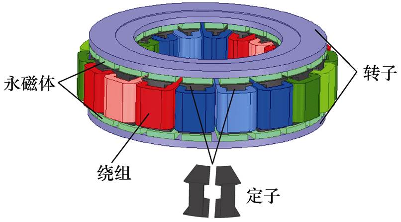
图1 双转子单定子轴向磁通永磁电机
Fig.1 Double-rotor single-stator axial flux permanent magnet motor
摘要 轴向磁通永磁电机的扁铜线交流铜耗会严重影响电机性能,因此扁铜线交流铜耗的精确计算与抑制十分重要。采用三维瞬态场计算交流铜耗,虽然可以获得精确的结果,但存在计算时间长和对计算机性能要求高的问题。为了权衡计算精度与计算时间,提出一种混合解析计算的方法。该方法将三维有限元与解析法相结合,可以考虑趋肤效应、邻近效应和外部磁场对交流铜耗的影响。为了抑制交流铜耗,提出采用扁线立绕的导体排列方式。利用该方法对不同导体排列方式的交流铜耗和电机效率进行计算,并通过三维瞬态场有限元进行验证。最后,对一台60 kW的样机进行实验,实验结果、有限元结果和混合解析计算结果基本吻合,验证了混合解析计算的准确性和扁线立绕的有效性。
关键词:轴向磁通永磁电机 扁铜线 交流铜耗 混合解析计算 导体排列方式
轴向磁通永磁电机具有功率密度高、体积小等优势,适用于对电机性能和安装空间有较高要求的领域,如航空航天、可再生能源、电动汽车等[1-4]。高功率密度轴向磁通永磁电机的电磁负荷和热负荷都趋于极限,并且受到趋肤效应、邻近效应和外部磁场的影响,导致绕组交流铜耗较大、温升较高,将严重影响电机的性能和绝缘材料的寿命[5-8]。因此,需要对绕组交流铜耗进行精确的计算。
轴向磁通永磁电机的绕组交流铜耗适合采用三维有限元进行精确计算[9]。文献[10]为了分析轴向磁通永磁电机利兹线绕组的交流铜耗,基于三维有限元提出了单根绕组等效建模法。文献[11]基于简化的导体三维模型计算了圆铜线绕组的交流铜耗。采用三维瞬态场有限元计算交流铜耗,虽然可以获得精确的结果,但存在计算时间长和对计算机性能要求高的问题。为了权衡计算精度与计算时间,提出了混合解析法[12-13]。文献[14]采用二维混合解析法计算交流铜耗,该方法仅对绕组截面的磁通密度进行采样,虽然可以加快计算速度,但是无法考虑绕组端部效应,不适用于轴向磁通永磁电机。为解决此问题,文献[15]中提出了三维混合解析法,但是该方法并不适用所有情况,其仅适用于交流铜耗主要由外部磁场引起的情况。
在高功率密度电机领域中,扁铜线因槽满率高、散热性能优异而被采用,但扁铜线具有更高的交流铜耗[16-18]。因此,需要对扁铜线绕组的交流铜耗进行抑制。在文献[19-20]中通过优化转子结构来降低绕组交流铜耗。而文献[21]通过合理选择扁铜线的匝数与并联根数来降低交流铜耗,这些方法需要大量的时间来改变电机的设计方案。在文献[22-23]中提出用导体换位法来抑制绕组交流铜耗。文献[24]利用利兹线导体间充分换位的方式有效地抑制了绕组交流铜耗。文献[25]分析了圆铜线的排布方式对交流铜耗的影响,实验结果证明,将导体尽可能全部布置在槽底会减小交流铜耗。但是这种绕组排布方式会造成散热困难,在高功率密度电机中会加速绕组绝缘材料老化,降低电机运行的可靠性。
综上所述,为了平衡扁铜线交流铜耗的计算精度和计算时间,本文提出一种混合解析计算的方法。该方法将三维有限元与解析法相结合,可以考虑趋肤效应、邻近效应和外部磁场对交流铜耗的影响。提出扁线立绕的导体排列方式来抑制交流铜耗,并通过混合解析计算与三维瞬态场有限元分析了不同导体排列方式对交流铜耗和效率的影响。最后,进行样机实验,验证了混合解析计算方法的准确性和扁线立绕的有效性。
本文对双转子单定子轴向磁通永磁电机进行研究,其结构如图1所示。定子之间不存在轭部,这种结构可以减轻定子铁心质量,提高电机的功率密度。同时还采用分数槽集中绕组,绕组缠绕在独立的定子上,可以减小绕组端部长度,降低绕组铜耗。电机定子槽口漏磁较多,而此拓扑结构具有两个槽口,会增加绕组的交流铜耗。

图1 双转子单定子轴向磁通永磁电机
Fig.1 Double-rotor single-stator axial flux permanent magnet motor
图1中绕组是简化的三维等效模型,采用此等效模型计算交流铜耗会产生很大的误差。因此,为了准确地计算交流铜耗,根据绕组实际尺寸,建立详细的绕组模型。
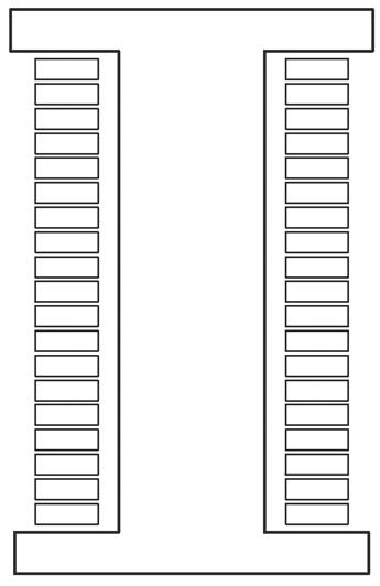
扁铜线具有散热性能优异、直流电阻小和结构紧凑等优势,同时电机定子槽型为矩形,采用扁铜线可以提高电机的槽满率,因此在本文电机设计方案中绕组为扁铜线。从图2所示的扁线平绕详细模型中可以看出扁铜线的排列方式,并命名这种排列方式为扁线平绕,图2a为扁线平绕的三维详细模型,图2b为扁线平绕的二维截面模型。
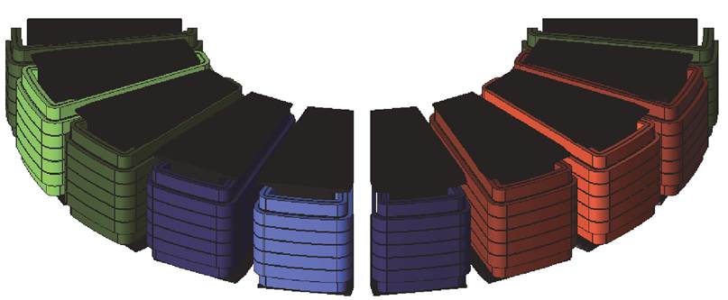
(a)三维模型
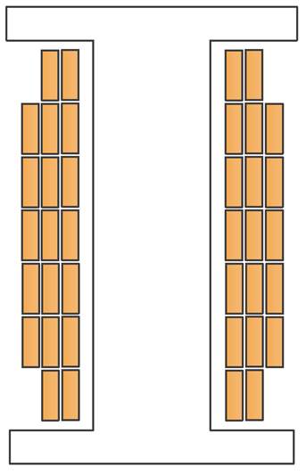
(b)二维截面
图2 扁线平绕详细模型
Fig.2 Detailed model of flat wire parallel winding
为解决三维瞬态场有限元计算交流铜耗存在计算时间较长和对计算机性能要求高的问题,本文提出一种混合解析计算的方法。该方法将三维有限元仿真与解析公式相结合,以三维涡流场有限元计算的磁通密度为基础,再利用解析公式计算出扁铜线交流铜耗。
在三维涡流场中建立扁铜线详细模型,并计算磁通密度。因为计算精确的磁通密度所需要的网格密度远远小于计算精确的交流铜耗所需要的网格密度,所以具有求解速度更快和计算资源要求更低的优势。混合解析计算需要对磁通密度进行采样,本文将采用分部分、分段和分层相结合的采样方式。
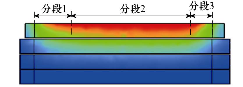
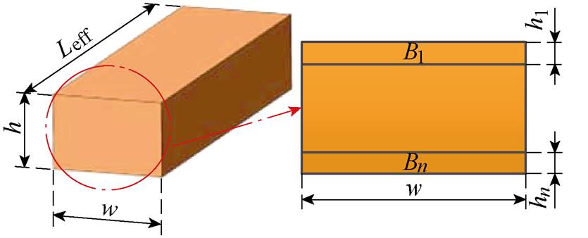
因为建立三维模型可以考虑绕组端部效应,所以先将扁铜线绕组分成4个部分进行采样,分别为内径端部绕组部分、左侧槽内绕组部分、外径端部绕组部分和右侧槽内绕组部分,如图3a所示。每部分将分段进行采样,分段依据是每根导体的磁通密度分布情况。当单根导体磁通密度分布不均匀时,以磁通密度明显变化之处为分界线进行分段。以右侧槽内绕组第一根导体为例,分成3段进行采样,如图3b所示。为了减少采样点的数量,当单根导体磁通密度分布均匀时,导体不进行分段,作为一个整体进行采样。由于扁铜线受到趋肤效应、邻近效应和外部磁场的影响,磁通密度在单根导体截面上分布不均匀。为解决这个问题,每段将分成n个小截面进行采样,假设每个小截面上磁通密度分布是均匀的,并且在其有效长度上是恒定不变的,如图3c所示。图中,h为扁铜线导体高度,w为扁铜线导体宽度,Leff为扁铜线导体有效长度,hn为截面高度,Bn为截面磁通密度。
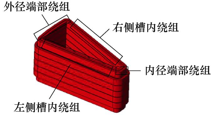
(a)采样部分
(b)采样分段
(c)采样截面
图3 磁通密度采样
Fig.3 Magnetic flux density sampling
基于采样坐标系确定每个采样点的坐标,如图4所示。采样点磁通密度可表示为Bqmn,其中q表示采样部分,m表示采样分段,n表示采样截面。当q=1时对应采样点在右侧槽内绕组,当q=2时对应采样点在外径端部绕组,当q=3时对应采样点在左侧槽内绕组,当q=4时对应采样点在内径端部绕组。以右侧槽内绕组和外径端部绕组为例,分别推导采样点坐标的表达式。右侧槽内绕组采样点B1mn的坐标为
 (1)
(1)
 (2)
(2)
 (3)
(3)
 (4)
(4)
式中,x1mn、y1mn、z1mn分别为右侧槽内绕组采样点的x轴、y轴和z轴坐标;z1m(n-1)为右侧槽内绕组采样点上一个小截面的z轴坐标,其中z1m0为右侧槽内导体初始z轴坐标;m和n都为从1开始逐渐递增的正整数,最大值取决于导体磁通密度的分布情况;d1为右侧槽内绕组到原点的最大距离;Leff1mn为右侧槽内绕组采样点所在分段的长度;q1为最内侧绕组的跨度角;q2为最内侧绕组与采样点的跨度角;hmn为采样点所在小截面的高度;hm(n-1)为采样点上一个小截面的高度,其中hm0=0。

图4 采样坐标系
Fig.4 Sampling coordinate system
外径端部绕组采样点B2mn的坐标为
 (5)
(5)
 (6)
(6)
 (7)
(7)
式中,x2mn、y2mn、z2mn分别为外径端部绕组采样点的x轴、y轴和z轴坐标;z2m(n-1)为外径端部绕组采样点上一个小截面的z轴坐标,其中z2m0为外径端部导体初始z轴坐标;d2为外径端部绕组的内侧到原点的最大距离;Leff2mn为外径端部绕组采样点所在分段的长度;Leff2(m+1)n为外径端部绕组采样点下一分段的长度。
由趋肤效应、邻近效应和外部磁场引起的附加铜耗定义为绕组涡流损耗。交流铜耗Pac由直流铜耗Pdc和绕组涡流损耗Peddy组成,有
 (8)
(8)
其中,直流铜耗为
 (9)
(9)
式中,mp为电机相数;I为相电流;Rdc为直流电阻。
因为每段导体分成n个小截面进行采样,所以根据叠加原理将每个小截面的绕组涡流损耗相加就是每段导体的绕组涡流损耗[15],有
 (10)
(10)
式中,w 为角频率;s 为铜的电导率;Btn为每个截面磁通密度切向分量;Bln为每个截面磁通密度轴向分量。
因为对每部分导体分段进行采样,所以根据叠加原理将每段的绕组涡流损耗相加就是每部分导体的绕组涡流损耗,有
 (11)
(11)
式中,Leffmn为每段导体有效长度;Btmn为每段导体磁通密度切向分量;Blmn为每段导体磁通密度轴向分量。
因为单根导体分部分进行采样,所以根据叠加原理将每部分的绕组涡流损耗相加就是单根导体的绕组涡流损耗,有
 (12)
(12)
式中,Leffqmn为每部分导体有效长度;hqmn为每部分导体截面高度;Btqmn为每部分导体磁通密度切向分量;Blqmn为每部分导体磁通密度轴向分量。
绕组总涡流损耗就是将每根扁铜线绕组涡流损耗相加,有
 (13)
(13)
式中,N为导体数量;LeffNqmn为每根导体有效长度;hNqmn为每根导体截面高度;BtNqmn为每根导体磁通密度切向分量;BlNqmn为每根导体磁通密度轴向 分量。
为了验证混合解析计算的准确性,本文对一台额定功率为60 kW的轴向磁通永磁电机进行三维有限元分析,电机主要参数见表1。
表1 电机主要参数
Tab.1 Main parameters of motor

参 数数 值 额定功率/kW60 峰值功率/kW140 额定转速/(r/min)2 500 功率密度/(kW/kg)7 定子槽18 极对数10
图5为扁线平绕三维磁通密度分布,槽内扁铜线磁通密度分布规律为越靠近槽口,其幅值越大。端部绕组的磁通密度也符合同样的规律,但是其幅值小于槽内绕组。图6为扁线平绕三维电流密度分布,其槽口处导体电流密度分布更不均匀,更趋近于导体表面。
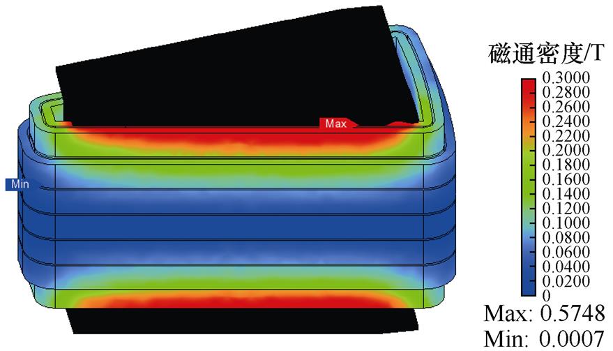
图5 扁线平绕三维磁通密度分布
Fig.5 Three-dimensional magnetic flux density distribution of flat wire parallel winding
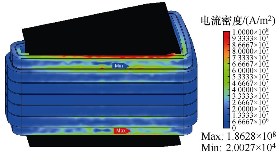
图6 扁线平绕三维电流密度分布
Fig.6 Three-dimensional current density distribution of flat wire parallel winding
当电机为额定工况时,分别利用三维瞬态场有限元和混合解析计算对每根导体的交流铜耗进行计算,如图7所示。将三维瞬态场有限元结果和混合解析计算结果进行对比,两者的吻合度较高。槽内导体每一列的分布规律都是沿轴向方向先减小后增大,在槽中心处达到最小值。每一行的分布规律都是沿着周向方向逐渐减小。
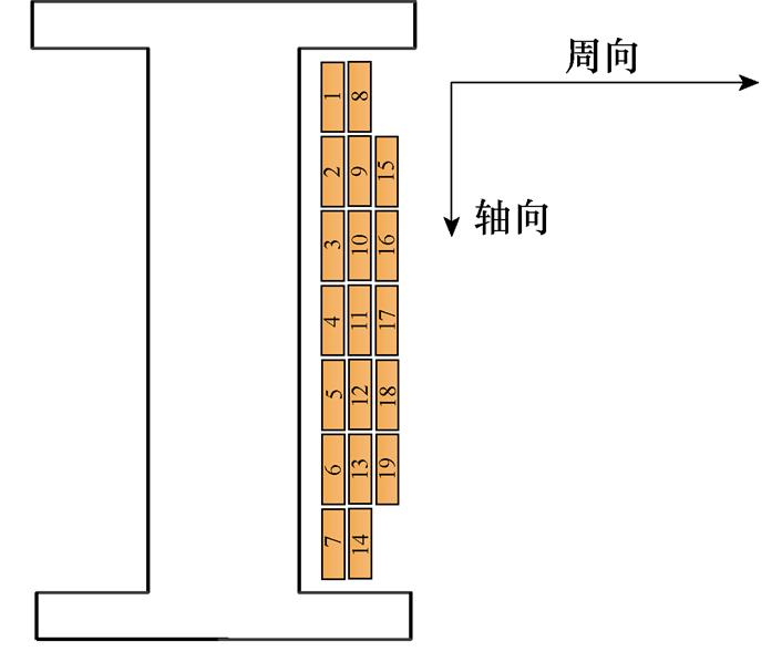
(a)扁线平绕导体编号
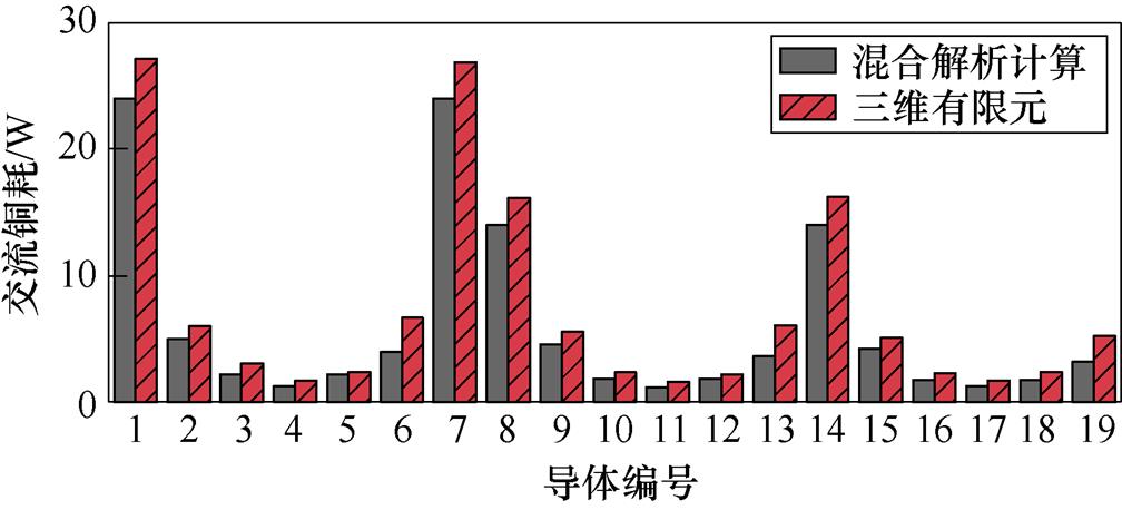
(b)导体交流铜耗对比
图7 扁线平绕导体交流铜耗
Fig.7 Flat wire parallel winding conductor AC copper loss
通过改变电机转速,研究不同频率时两种方法对计算交流铜耗的影响如图8所示。随着频率升高,扁线平绕的交流铜耗增加的速率越来越大,证明频率是影响交流铜耗的重要因素。扁线平绕交流铜耗的有限元结果与混合解析计算结果的对比见表2。随着频率升高,两种方法的交流铜耗误差逐渐增大,这是因为绕组涡流损耗占总交流铜耗的比例逐渐增大。
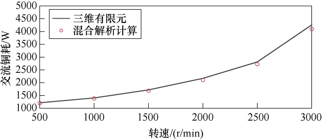
图8 不同速度扁线平绕交流铜耗
Fig.8 AC copper loss of flat wire parallel winding at different speeds
为了抑制扁线平绕的交流铜耗,将采用不同的导体排列方式,并命名为扁线立绕。图9a为扁线立绕的三维详细模型,图9b为扁线立绕的二维截面模型。
表2 扁线平绕交流铜耗对比
Tab.2 Comparison of AC copper loss of flat wire parallel winding

转速/(r/min)铜耗/W误差(%) 混合解析计算三维有限元 5001 199.11 213.81.21 1 0001 3811 405.11.72 1 5001 684.91 725.12.33 2 0002 1082 170.32.87 2 5002 723.72 818.63.37 3 0004 101.14 268.73.93
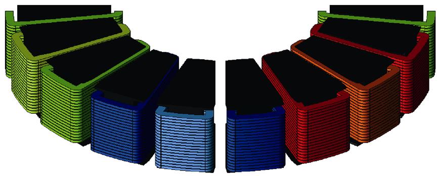
(a)三维模型
(b)二维截面
图9 扁线立绕详细模型
Fig.9 Detailed model of flat wire vertical winding
图10为扁线立绕三维磁通密度分布,槽口处导体磁通密度幅值最大,与扁线平绕相比,磁通密度较大的导体数量降低。图11为扁线立绕三维电流密度分布,槽口处导体电流密度分布更趋近于表面,电流密度分布不均匀的导体数量降低。
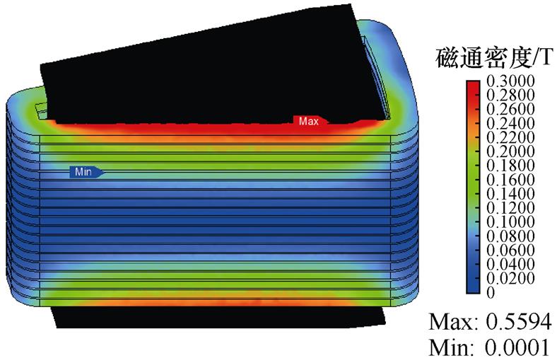
图10 扁线立绕三维磁通密度分布
Fig.10 Three-dimensional magnetic flux density distribution of flat wire vertical winding
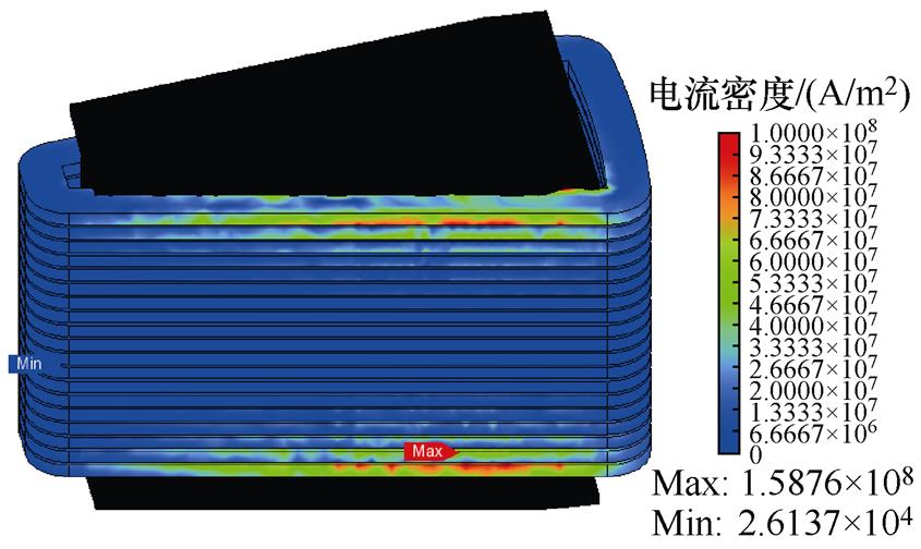
图11 扁线立绕三维电流密度分布
Fig.11 Three-dimensional current density distribution of flat wire vertical winding
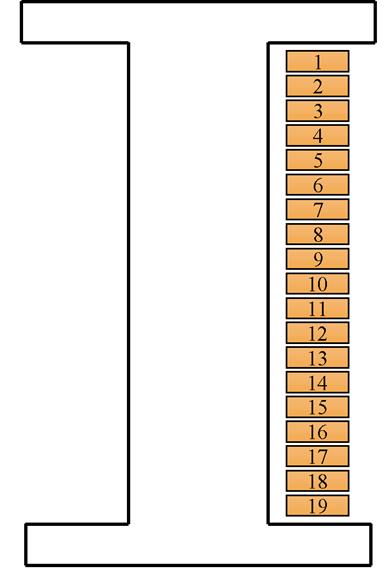
将扁线立绕的导体进行编号,当电机为额定工况时,分别利用三维瞬态场有限元和混合解析计算对每根导体的交流铜耗进行计算,如图12所示。扁线立绕交流铜耗的轴向分布规律与扁线平绕相同。对比图7和图12可知,扁线平绕中导体7、8和14更靠近槽口处,而扁线立绕中导体19更靠近槽口处,这些导体的交流铜耗会更大,这个现象符合磁通密度与电流密度的分布规律。因此,设计电机时应选择槽口导体数量较少的排列方式。
(a)扁线立绕导体编号
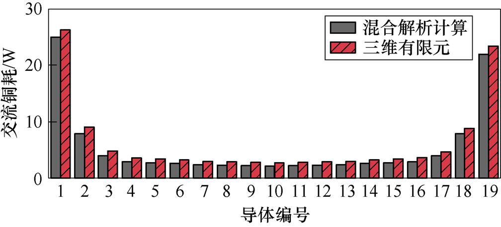
(b)导体交流铜耗对比
图12 扁线立绕导体交流铜耗
Fig.12 Flat wire vertical winding conductor AC copper loss
图13为不同转速时分别采用混合解析计算和三维瞬态场有限元计算的扁线立绕交流铜耗结果。扁线立绕交流铜耗的有限元结果与混合解析计算结果的对比见表3。对比表2和表3可以看出,扁线平绕的交流铜耗一直大于扁线立绕,并且随着电机转速增加,电机频率迅速升高,两者的交流铜耗差也越来越大。通过对比三维瞬态场有限元仿真结果,在额定工况下,扁铜线交流铜耗减小了36.9%。
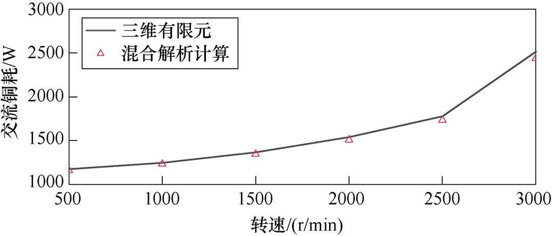
图13 不同转速扁线立绕交流铜耗
Fig.13 AC copper loss of flat wire vertical winding at different speeds
表3 扁线立绕交流铜耗对比
Tab.3 Comparison of AC copper loss of flat wire vertical winding

转速/(r/min)铜耗/W误差(%) 混合解析计算三维有限元 5001 160.51 173.11.07 1 0001 230.21 246.51.31 1 5001 345.81 368.11.63 2 0001 507.51 538.22 2 5001 734.51 777.32.41 3 0002 436.52 516.13.16
与三维瞬态场有限元相比,混合解析计算的最大误差为3.93%。三维瞬态场有限元的计算时间为49 h,混合解析计算的计算时间为1 h,计算时间缩短了97.96%。因此,利用该方法计算交流铜耗具有计算精度高和计算时间短的优势。
为了全面对比两种导体排列方式,利用混合解析计算和三维瞬态场有限元分别计算了三种常用工况下电机的交流铜耗和效率。电机的三种工况见表4。工况Ⅰ为相对低速大转矩工况,工况Ⅱ为额定工况,工况Ⅲ为相对高速工况。
表4 电机三种工况
Tab.4 Three working conditions of motor

工况转速/(r/min)频率/Hz转矩/(N·m) Ⅰ50083.3260 Ⅱ2 500416.7210 Ⅲ4 000666.7160
图14和图15分别为两种导体排列方式在不同工况下的交流铜耗和效率,混合解析计算与三维瞬态场有限元的计算结果吻合度较高。在工况Ⅰ下,扁线平绕的交流铜耗略高于扁线立绕,因为转速较低,绕组涡流损耗占总交流铜耗的比例不大。在工况Ⅱ和工况Ⅲ下,扁线立绕的效率明显大于扁线平绕。因为频率迅速升高,绕组涡流损耗占总交流铜耗的比例变大。综上所述,扁线立绕电机的性能要优于扁线平绕电机,证明了扁线立绕的有效性。为充分发挥扁铜线优势,需要通过选择合理的导体排列方式来抑制扁铜线交流铜耗,并提高电机效率。
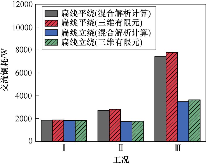
图14 不同工况交流铜耗
Fig.14 AC copper loss under different working conditions
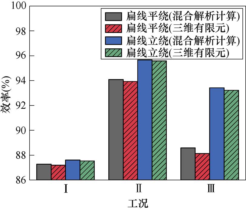
图15 不同工况效率
Fig.15 Efficiency under different working conditions
为了验证混合解析计算的准确性,根据表1电机参数,设计并制造了一台样机。绕组的线型为扁铜线,并采用扁线立绕的导体排列方式。扁铜线结构与样机如图16所示,样机实验平台如图17所示。额定转速2 500 r/min的线空载反电动势波形如图18所示,证明样机满足设计条件可正常运行。
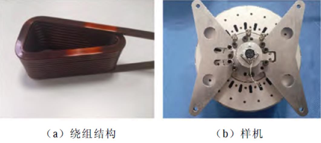
图16 绕组结构与样机
Fig.16 Winding structure and prototype
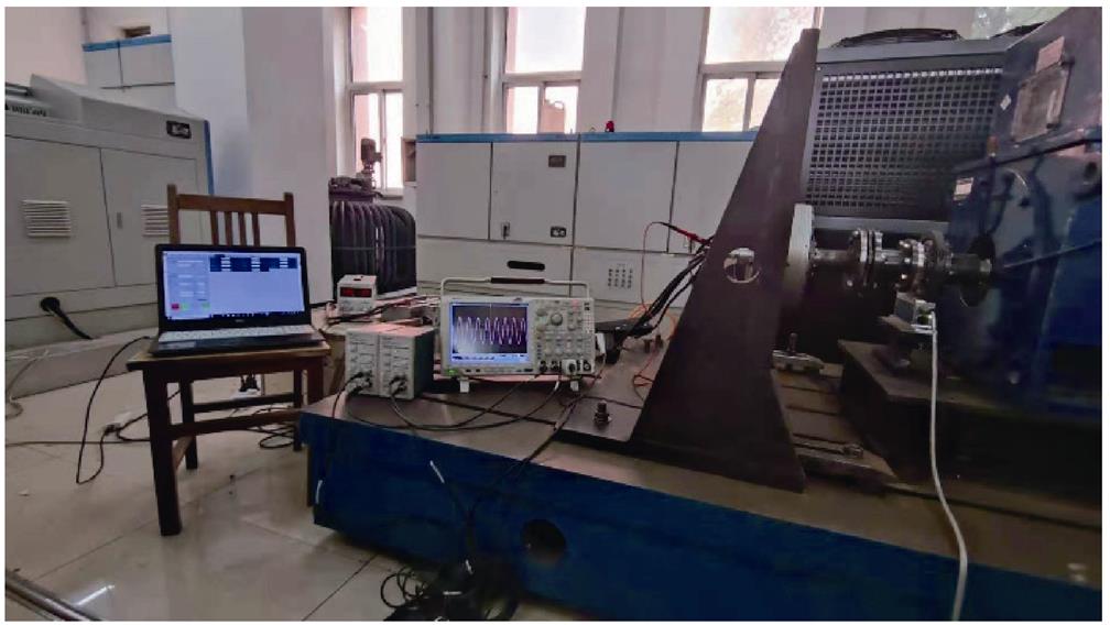
图17 电机测试实验平台
Fig.17 Motor testing experimental platform
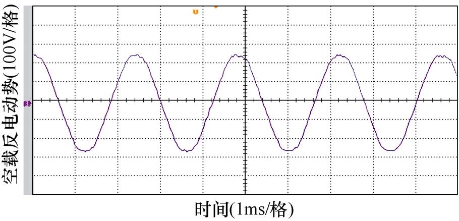
图18 空载反电动势波形
Fig.18 No-load back-electromotive force waveform
转速为2 500 r/min时的相电流与效率的关系如图19所示。混合解析计算与实验的误差很小,在合理的范围之内。产生误差的原因是当相电流较小时,机械损耗的计算值和实验值存在误差,机械损耗所占比例较大,因此导致混合解析计算的效率高于实验效率。综上所述,实验结果、三维有限元仿真结果和混合解析计算结果均基本吻合,证明了混合解析计算的准确性与扁线立绕的有效性。
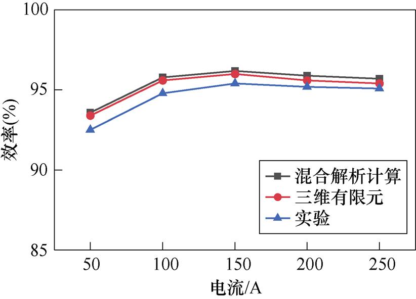
图19 效率对比
Fig.19 Comparison of efficiency
本文将三维有限元与解析法相结合,提出一种混合解析计算的方法来快速计算扁铜线交流铜耗。同时提出扁线立绕的导体排列方式来抑制扁铜线交流铜耗。对不同工况和不同导体排列方式的交流铜耗和效率进行了分析研究。通过对比混合解析计算结果、三维瞬态场有限元仿真结果和实验结果,得到以下结论:
1)本文提出扁线立绕的导体排列方式,可以有效抑制扁铜线交流铜耗,提高电机效率。在额定工况下,与扁线平绕相比,扁线立绕的交流铜耗减小了36.9%。并且随着频率增加,差异越来越明显。因此,为抑制交流铜耗应尽可能减小槽口处的导体数量,选择合适的导体排列方式。为在不改变电机拓扑结构的前提下,抑制扁铜线交流铜耗提供了参考。
2)混合解析计算方法可以考虑趋肤效应、邻近效应和外部磁场对扁铜线交流铜耗的影响。利用该方法计算交流铜耗具有计算精度高和计算时间短的优势。该方法还适用于快速分析不同扁铜线排列方式对交流铜耗的影响,为快速准确地计算扁铜线交流铜耗提供了参考,同时也为优化高功率密度电机设计提供了基础。
参考文献
[1] Cheng Wenjie, Cao Guangdong, Deng Zhikai, et al. Analytical solution for electromagnetic torque of ultrahigh speed AFPM motor with slotless stator core and toroidal coils[J]. IEEE Transactions on Magnetics, 2021, 57(2): 1-5.
[2] 张文晶, 徐衍亮, 李树才. 新型盘式横向磁通永磁无刷电机的结构原理及设计优化[J]. 电工技术学报, 2021, 36(14): 2979-2988.
Zhang Wenjing, Xu Yanliang, Li Shucai. Structure principle and design optimization of a new type of disk transverse flux permanent magnet brushless motor[J]. Transactions of China Electrotechnical Society, 2021, 36(14): 2979-2988.
[3] 徐衍亮, 崔波, 张文晶, 等. 软磁复合材料-Si钢组合铁心盘式横向磁通永磁无刷电机[J]. 电工技术学报, 2020, 35(5): 983-990.
Xu Yanliang, Cui Bo, Zhang Wenjing, et al. Disk transverse flux permanent magnet brushless motor based on soft magnetic composite-Si steel core[J]. Transactions of China Electrotechnical Society, 2020, 35(5): 983-990.
[4] 朱龙飞, 朱建国, 佟文明, 等. PWM逆变器供电引起的轴向磁通非晶电机谐波损耗的解析计算[J]. 电工技术学报, 2017, 32(16): 115-123.
Zhu Longfei, Zhu Jianguo, Tong Wenming, et al. Analytical calculation of harmonic losses of an axial flux amorphous motor caused by PWM inverter supplying[J]. Transactions of China Electrotechnical Society, 2017, 32(16): 115-123.
[5] Payza O, Demir Y, Aydin M. Investigation of losses for a concentrated winding high-speed permanent magnet-assisted synchronous reluctance motor for washing machine application[J]. IEEE Transactions on Magnetics, 2018, 54(11): 1-5.
[6] 骆凯传, 师蔚, 张舟云. 基于温度实验的永磁同步电机损耗分离方法[J]. 电工技术学报, 2022, 37(16): 4060-4073.
Luo Kaichuan, Shi Wei, Zhang Zhouyun. Method of loss separation of permanent magnet synchronous motor based on temperature experiment[J]. Transa- ctions of China Electrotechnical Society, 2022, 37(16): 4060-4073.
[7] 许欣, 邓智泉, 张忠明, 等. 高速电机定子单槽绕组交流损耗近似解析建模及验证[J]. 中国电机工程学报, 2021, 41(12): 4306-4316.
Xu Xin, Deng Zhiquan, Zhang Zhongming, et al. Approximate analytical modeling and verification of AC loss of stator single slot winding of high-speed motor[J]. Proceedings of the CSEE, 2021, 41(12): 4306-4316.
[8] 张琪, 张俊, 黄苏融, 等. 集肤效应对高密度永磁电机温升的影响[J]. 电机与控制应用, 2013, 40(8): 35-39.
Zhang Qi, Zhang Jun, Huang Surong, et al. Influence of skin effect on temperature rise of high density permanent magnet motor[J]. Electric Machines & Control Application, 2013, 40(8): 35-39.
[9] Aliyu N, Ahmed N, Stannard N, et al. AC winding loss reduction in high speed axial flux permanent magnet machines using a lamination steel sheet[C]// 2019 IEEE International Electric Machines & Drives Conference (IEMDC), San Diego, CA, USA, 2019: 1053-1060.
[10] Geng Weiwei, Zhang Zhuoran. Analysis and imple- mentation of new ironless stator axial-flux permanent magnet machine with concentrated nonoverlapping windings[J]. IEEE Transactions on Energy Con- version, 2018, 33(3): 1274-1284.
[11] Heins G, Ionel D M, Patterson D, et al. Combined experimental and numerical method for loss separation in permanent-magnet brushless machines[J]. IEEE Transactions on Industry Applications, 2016, 52(2): 1405-1412.
[12] Fatemi A, Ionel D M, Demerdash N A O, et al. A computationally efficient method for calculation of strand eddy current losses in electric machines[C]// 2016 IEEE Energy Conversion Congress and Expo- sition (ECCE), Milwaukee, WI, USA, 2017: 1-8.
[13] Volpe G, Popescu M, Marignetti F, et al. Modelling AC winding losses in a PMSM with high frequency and torque density[C]//2018 IEEE Energy Conversion Congress and Exposition (ECCE), Portland, OR, USA, 2018: 2300-2305.
[14] Mohammed O A, Ganu S. FE-circuit coupled model of electric machines for simulation and evaluation of EMI issues in motor drives[J]. IEEE Transactions on Magnetics, 2010, 46(8): 3389-3392.
[15] Taran N, Ionel D M, Rallabandi V, et al. An overview of methods and a new three-dimensional FEA and analytical hybrid technique for calculating AC winding losses in PM machines[J]. IEEE Transactions on Industry Applications, 2021, 57(1): 352-362.
[16] 高华敏, 张卓然, 王晨, 等. 定子无铁心轴向磁场永磁轮毂电机损耗分析及效率优化[J]. 中国电机工程学报, 2021, 41(6): 2002-2012.
Gao Huamin, Zhang Zhuoran, Wang Chen, et al. Loss analysis and efficiency optimization of stator coreless axial magnetic field permanent magnet hub motor[J]. Proceedings of the CSEE, 2021, 41(6): 2002-2012.
[17] 朱洒, 曾峰, 陆剑波, 等. 考虑PWM谐波损耗的车用扁线内嵌式永磁同步电机效率图简化工程计算[J]. 电工技术学报, 2022, 37(22): 5687-5703.
Zhu Sa, Zeng Feng, Lu Jianbo, et al. Simplified engineering calculation of efficiency map of interior permanent magnet synchronous machines with hairpin windings considering PWM-induced harmonic losses[J]. Transactions of China Electrotechnical Society, 2022, 37(22): 5687-5703.
[18] Zhang Jian, Zhang Zhuoran, Xia Yiwen, et al. Thermal analysis and management for doubly salient brushless DC generator with flat wire winding[J]. IEEE Transactions on Energy Conversion, 2020, 35(2): 1110-1119.
[19] Liu Kai, Yin Ming, Hua Wei, et al. Design and optimization of an external rotor ironless BLDCM used in a flywheel energy storage system[J]. IEEE Transactions on Magnetics, 2018, 54(11): 1-5.
[20] Luo Ciyong, Sun Jun, Liao Yong, et al. Analysis and design of ironless toroidal winding of tubular linear voice coil motor for minimum copper loss[J]. IEEE Transactions on Plasma Science, 2019, 47(5): 2369- 2375.
[21] Popescu M, Dorrell D G. Proximity losses in the windings of high speed brushless permanent magnet AC motors with single tooth windings and parallel paths[J]. IEEE Transactions on Magnetics, 2013, 49(7): 3913-3916.
[22] Ishigohka T, Ninomiya A, Yamaguchi S, et al. Effect of impedance distributions on current imbalance in insulated multi-stranded superconducting conductor[J]. IEEE Transactions on Applied Superconductivity, 2000, 10(1): 1216-1219.
[23] Bian Xu, Liang Yanping. Circuit network model of stator transposition bar in large generators and calculation of circulating current[J]. IEEE Transa- ctions on Industrial Electronics, 2015, 62(3): 1392- 1399.
[24] Zheng Liping, Wu T X, Acharya D, et al. Design of a super-high speed permanent magnet synchronous motor for cryogenic applications[C]//IEEE Inter- national Conference on Electric Machines and Drives, San Antonio, TX, USA, 2005: 874-881.
[25] Mellor P, Wrobel R, McNeill N. Investigation of proximity losses in a high speed brushless permanent magnet motor[C]//Conference Record of the 2006 IEEE Industry Applications Conference Forty-First IAS Annual Meeting, Tampa, FL, 2006: 1514-1518.
Hybrid Analytical Calculation and Suppression of AC Copper Loss of Flat Copper Wire in Axial Flux Permanent Magnet Motor
Abstract Axial flux permanent magnet motor is suitable for the field with high requirements on motor perfor- mance and installation space due to advantages such as high-power density, small volume, and light mass. In the field of high-power density motors, flat copper wire is used for its high slot-filling rate and excellent heat dissipation performance. However, due to the influence of skin effect, proximity effect, and external magnetic field, the flat copper wire has a higher AC copper loss, which can seriously affect the motor performance and the insulating material life. Therefore, accurate calculation and suppression of AC copper loss of flat copper wire are significant.
Although accurate results can be obtained using the three-dimensional transient field to calculate AC copper loss, some issues, such as long computing time and high computer performance requirements, could be improved. Therefore, a hybrid analytical calculation method is proposed to balance calculation accuracy and calculation time. This method combines the three-dimensional finite element with the analytical method, which can consider the influence of skin effect, proximity effect, and external magnetic field on AC copper loss. Meanwhile, a conductor arrangement of flat wire vertical winding is proposed to suppress AC copper loss.
Firstly, according to the actual size of the winding, a detailed three-dimensional model of flat copper wire is established in the eddy current field, and the magnetic flux density is calculated. Secondly, the combined sampling method of parts, segments, and layers is adopted. Finally, the sampling magnetic flux density is combined with the analytical model to calculate the AC copper loss.
A 60 kW, 18-slot, 20-pole double-rotor single-stator axial flux permanent magnet motor was taken as an example. Firstly, the proposed method analyzed the AC copper loss of different conductor arrangements, verified by a three-dimensional transient field finite element. The AC copper loss of the flat wire vertical winding is reduced by 36.9% compared with that of the flat wire parallel winding, and the hybrid analytical calculation time is reduced by 97.96% compared with the three-dimensional transient finite element. Secondly, the AC copper loss and motor efficiency under different working conditions were analyzed. The flat wire vertical winding motor’s performance is better than the flat wire parallel winding motor in all working conditions, and its advantages are more obvious with the increase in frequency. Finally, the prototype was tested. The experimental results, the finite element results, and the hybrid analytical calculation results were almost consistent, which verified the accuracy of the hybrid analytical calculation and the effectiveness of the flat wire vertical winding.
The following conclusions can be obtained by comparing the calculation results of the three methods: (1) The conductor arrangement of flat wire vertical winding is proposed, effectively suppressing the AC copper loss of flat copper wire and improving motor efficiency. The number of conductors at the slot opening should be reduced, and the conductor arrangements should be changed to suppress AC copper loss without changing the motor topology structure. (2) The influence of skin effect, proximity effect, and external magnetic field on AC copper loss of flat copper wire can be considered by the hybrid analytical calculation method. This method has the advantages of high accuracy and short calculation time in calculating AC copper loss, which is also suitable for rapidly analyzing the effect of different flat copper wire conductor arrangements on AC copper loss.
keywords:Axial flux permanent magnet motor, flat copper wire, AC copper loss, hybrid analytical calculation, conductor arrangement
中图分类号:TM351
DOI: 10.19595/j.cnki.1000-6753.tces.221828
国家自然科学基金面上项目(51877139)和辽宁省教育厅科学研究经费(面上项目)(LJKZ0128)资助。
收稿日期 2022-09-30
改稿日期 2023-03-22
武 岳 男,1995年生,博士研究生,研究方向为轴向磁通永磁电机设计、控制及多物理场分析。E-mail: wuyue_95@126.com
张志锋 男,1981年生,教授,博士生导师,研究方向为特种电机设计及其控制。E-mail: zzf_sut@126.com(通信作者)
(编辑 崔文静)