图1 七阶电力系统电气结构
Fig.1 Electrical structure diagram of seventh-stage power system
摘要 当电力系统参数变动或遭受扰动后,系统极易进入局部混沌振荡状态,局部的功角振荡可能会演化为大范围的系统振荡,最终可能造成系统解列等严重后果。因此,抑制电力系统的局部混沌振荡状态具有重要意义。为抑制七阶系统的混沌状态,增强系统的抗扰能力,采用扩张观测器对系统发电机侧与负荷侧的系统项进行观测,设计了基于全局滑模的容错控制器。该文考虑了发电机侧遭受扰动与负荷侧控制器故障的情况。为减少系统在扰动下的最大偏差与稳态误差,并补偿控制器故障导致的输出幅值损失,设计了基于全局滑模的自适应容错控制器。仿真结果表明,当系统分别遭受传输故障、阶跃扰动及控制器故障时,系统在基于自适应全局滑模的容错控制器的作用下均能有效收敛至目标轨道。
关键词:电力系统 混沌 全局滑模 自适应 扩张观测器
当电力系统遭受外部扰动或参数在某一特定范围内发生变化时,系统功角可能在一定范围内出现无序振荡现象,即系统进入混沌状态。近年来,新能源发电大量接入电力系统,缓解了传统发电模式带来的能源和环境问题。相对于传统能源系统,新能源发电功率的不确定性可视为传统系统的参数变化或外部扰动,极有可能使系统进入振荡状态,在没有得到及时有效的控制下,系统可能最终进入混沌状态[1-2]。
对于低阶模型,目前已有较多文献对其混沌特性分析与控制问题进行研究,提出了多种控制策略。文献[4-8]运用不同的控制理论对二阶模型进行控制器设计,达到良好的控制效果。文献[9-12]分别在不同方面对四阶模型进行混沌特性的分析,并设计了控制器。对于高阶模型,目前学术界普遍承认的最高阶模型为七阶系统模型,其相关研究仍然较少。对于七阶系统的混沌分析,文献[13]运用时域图、相图及庞加莱截面对系统通往混沌的道路进行了分析。对于七阶系统的控制,国内外学者将非线性理论推广至七阶系统中,从不同程度上消除了系统的混沌状态。文献[14]将储能装置添加到七阶电力系统中,使其成为一个十三阶系统,并根据各状态变量之间的耦合关系,将系统分为三个模块,根据反演定理,为各模块均设计了动态滑模面控制器,通过对各个模块的控制使系统各状态变量均收敛至目标轨道。文献[15]将一种新颖的协同控制策略推广至七阶电力系统的混沌控制,通过对所选变量的控制,消除系统各变量的振荡状态。文献[16]基于等效原理,将固定时间控制、自适应控制和滑模控制相结合,提出一种适用于七阶电力系统的自适应控制策略,该策略能保证七阶电力系统在有限时间内收敛至目标轨道。文献[17]运用时间尺度分离理论,设计了一种基于时间尺度分离的滑模控制策略,该控制策略中不含切换项,解决了控制器输出不连续的问题。目前相关文献中所设计的控制器虽能使被控对象收敛至目标轨道,但其控制器设计较为依赖系统的精确模型,并且大部分并未考虑系统在遭受扰动和发生故障时的情况,实用性相对较差。如果系统在遭受较大扰动导致系统模型出现变化,或出现控制器故障导致控制器输出信号幅值下降时,上述控制器可能没有足够的容错能力,导致系统状态偏离目标轨道。
本文建立了考虑外部扰动和控制器故障的七阶电力系统数学模型,并针对该模型设计了一种基于全局滑模的自适应容错控制策略(Adaptive Fault-Tolerant Control, AFTC)。该控制器不需要系统精确的数学模型,只需要系统各状态变量的信息,降低了控制器参数的整定难度,提高了控制器的通用性。针对七阶系统发电机侧易受干扰和负载侧控制器易发生故障的问题,在发电机侧控制器中采用固定增益与自适应增益相结合的控制策略,在负载侧控制器中采用自适应故障估计来补偿控制器故障造成的控制器输出损失。仿真结果表明,当系统在无扰动、外部阶跃扰动、传输故障及控制器故障的情况下,所设计的控制器均能使系统收敛到预定目标轨道附近。
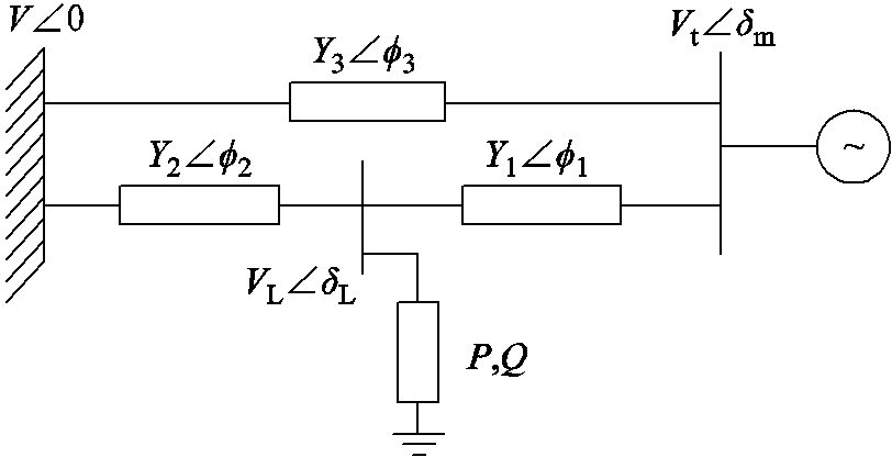
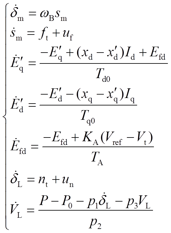
七阶电力系统是以典型的三节点电力系统为研究对象,其由发电机、负荷和无穷大系统组成,各部分之间通过输电线路连接。七阶电力系统电气结构如图1所示。
图1 七阶电力系统电气结构
Fig.1 Electrical structure diagram of seventh-stage power system
图1中,V为无穷大母线电压,Y1、Y2和Y3为输电网络中的各段线路的导纳值, 、
、 和
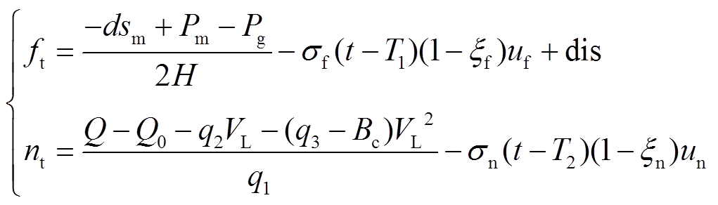
和 为各段线路的导纳角,Vt为发电机端电压幅值,δm为发电机功角,VL为负荷侧母线电压幅值,δL为负荷侧母线功角,P和Q分别为负荷侧母线的动态有功功率与无功功率。七阶电力系统模型表达式为
 (1)
(1)
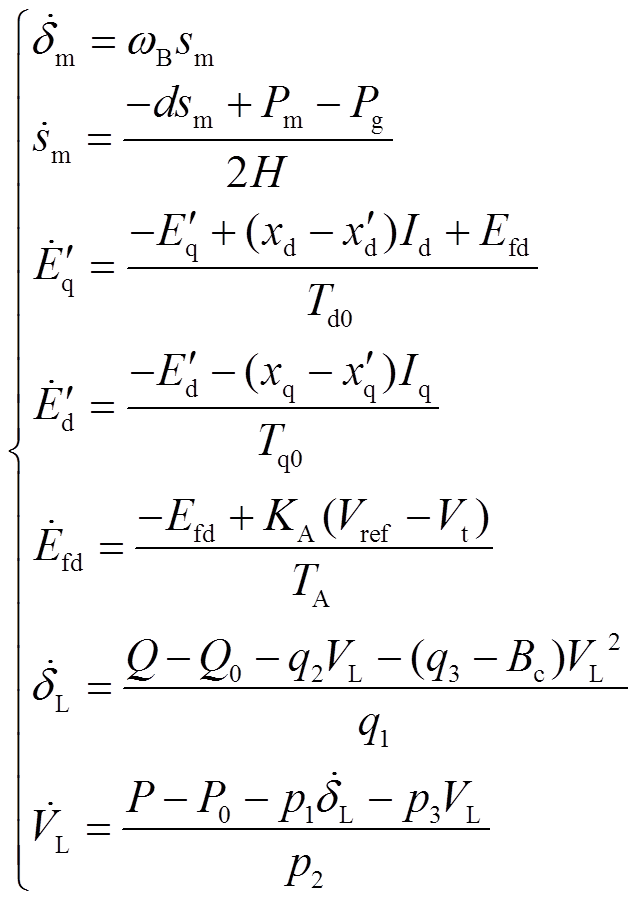
式中, 为发电机角频率;
 为发电机转差;d为发电机阻尼系数;
 为发电机原动机输入功率;
 为发电机发出的电磁功率;H为转子转动惯量常数;
 和
和 分别为发电机d轴和q轴的暂态电动势;
 和
和 分别为d轴的同步与暂态电抗;
 和
和 分别为q轴的同步与暂态电抗;
 和
和 分别为d轴和q轴电流;
 为励磁限制器输出电压;
 和
和 分别为d轴和q轴的暂态时间常数;
 为励磁环节常数增益,
 为参考电压;
 为发电机段电压幅值;
 为励磁环节时间常数;P和Q分别为综合负荷的有功与无功功率;
 和
和 分别为恒定负荷的有功与无功功率;
 、
、 、
、 、
、 、
、 、
、 、
、 均为动态负荷参数,其物理意义均取自文献[18-20]。
状态变量初始值的选取是系统能否产生混沌的关键条件之一。经过多组迭代,最终选取系统初始值为[1.3331 0 1.332678 -0.3283 4.198 0.2936 0.93]。
为研究七阶系统的动态特性,选取系统恒定负荷有功功率P0与无功功率Q0的典型参数为系统变量,其余参数取值均取自文献[14],观察此区间内系统功角的分岔图及在不同取值下系统的三维相图。
为分析综合负荷中P0的变化对七阶系统动态过程的影响,取Q0=0.6(pu),P0 {0.397,0.420}时,系统功角的分岔图和相图如图2a和图2b~图2e所示。
由图2可知,当P0=0.397(pu)时,系统处于混沌状态;随着P0的增加,当P0=0.397 9(pu)时系统经历逆向分岔转为4周期态;当P0=0.399 1(pu)时系统经历逆向分岔转为2周期态;当P0=0.405 5(pu)时系统再次经历逆向分岔,此后系统转为1周期态。此外,当P0>0.42(pu)和P0<0.397(pu)时,系统分别为1周期和混沌态。由此可得,当P0在一定范围内增加,系统经历逆向分岔后从混沌转为周期态。
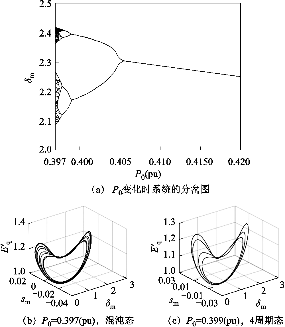
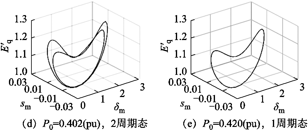
图2 P0变化时系统的分岔图与相图
Fig.2 Bifurcation diagram and phase diagram of the system when P0 changes
为分析综合负荷中 的变化对七阶系统动态过程的影响,取P0=0.4(pu),{0.500pu, 0.612pu}时,系统发电机功角的分岔图和三维相图如图3a和图3b~图3e所示。
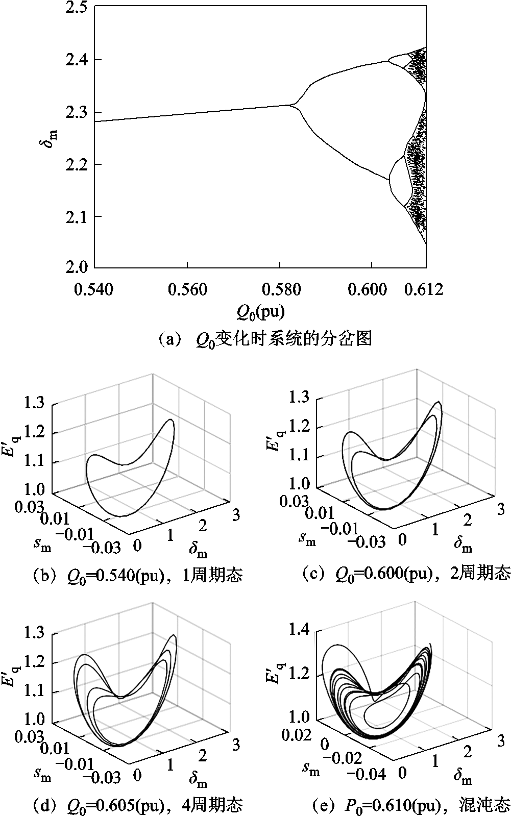
图3  变化时系统的分岔图与相图
Fig.3 Bifurcation diagram and phase diagram of the system when changes
由图3可知,当=0.540(pu)时,系统呈现1周期态;随着的增加,当=0.582 2(pu)时,系统经历正向分岔转为2周期态;当Q0=0.603 8(pu)时系统再次经历正向分岔转为4周期态;最终系统在 =0.607 5(pu)时进入混沌状态。此外,当>0.612(pu)和<0.540(pu)时,系统分别为混沌和1周期态。由此可得,当在一定范围内增加,系统经历正向分岔后从周期转为混沌态。
由此可知,在满足参数P0=0.4(pu),=0.61(pu)时,七阶电力系统处于混沌状态。
在电力系统中,信号传输元件的作用至关重要。而此类元件一般属于高敏感性元件,因而容易遭受干扰而导致其精度下降,从而使电力系统出现振荡现象。本文考虑被控系统与所设计观测器之间的传输故障的情况,被控对象数学模型为
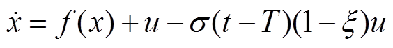 (2)
(2)
式中,x为状态变量; 为包含状态变量的非线性函数;u为控制器输出的控制量;
 为传输幅值损失程度,
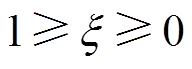 ,越小,传输幅值损失越大,当
 时,传输无故障;
 表达式为
表达式为
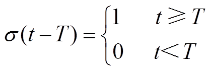 (3)
(3)
式中,T为故障发生时间。式(3)表示T时刻传感器发生故障。
在式(1)所示模型中,供电端稳定对电力系统稳定来说至关重要,首先要控制目标为稳定发电机功角,防止整个系统进入振荡状态;其次为保证负荷电压相角稳定,负荷端的首要控制目标为稳定负荷母线电压相角,故选择 与
与 为控制目标。结合式(2)可得考虑传输故障的电力系统模型为
 (4)
(4)
式中, 和
和 分别为发电机侧和负荷侧的控制器。
发电机为电力系统中的核心设备,为保证发电机的平稳运行,宜在发电机模型中考虑外部扰动dis的影响,得 与
与 为
为
 (5)
(5)
除发电机侧时常遭受各类扰动外,负荷端控制器由于工作环境复杂,使得控制器故障率大大提升,并且由于其远离操作中心,使得控制器发生故障时检修人员不能及时进行维修,进而可能导致负荷电压与相角偏离预定值,造成负荷电压质量降低。综上所述,负荷端控制器需要有一定的容错性,以应对可能发生的故障。
负荷端控制器发生故障时,控制器故障的数学模型为
 (6)
(6)
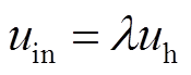
式中,uin为系统所接收到的控制信号;uh为控制器的理想输出信号; 为控制器故障导致的输出幅值损失程度,
 ,越小表示控制器输出幅值损失程度越高。
 表示负荷侧控制器无故障,
 表示负荷侧控制器完全故障。
滑模控制作为一种实用性很强的控制策略,已被运用在诸多领域中[21-26]。在传统的非线性滑模控制器的设计中,要求控制器输出中含有系统非线性项,故需已知系统准确的数学表达式及各参数值,给控制器的设计带来较大限制。非线性扩张观测器具有所需系统信息少、不依赖系统模型和观测精度高的优点。采用扩张观测器[27]对系统模型进行观测,并将所观测到的系统项输入控制器中,解决了由于故障和扰动而无法及时获取系统项变化的问题。
首先,设计观测器对同步发电机转子运行特性进行观测,由于发电机侧功角与系统项存在二阶导数关系。故设计如式(7)所示的三阶扩张观测器。
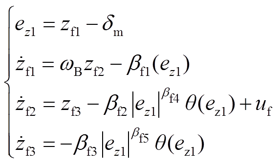 (7)
(7)
式中, 、
、 、
、 、
、 、
、 均为大于0的常数。观测器的收敛特性由、和的值决定,根据被观测对象的特性,一般取
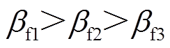 。而观测器的最终稳态误差由、的值决定,一般取
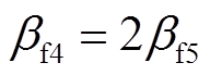 。为了减少控制系统的抖振现象,传统观测器中所使用的开关函数sgn由具有平滑特性的继电函数θ来代替[27]。
其次,对负荷侧母线设计观测器。由于负荷侧功角与负荷侧系统项的表达式存在一阶导数关系,设计如式(8)所示的二阶扩张观测器。
 (8)
(8)
式中, 、
、 、
、 均为大于0的常数。观测器的收敛特性由根据被观测对象的特性和的值决定,一般取
 。而观测器的最终稳态误差由的值决定,一般取
 。
。
令 ,
, ,在观测器(7)和观测器(8)的作用下,
 与
与 将分别以一定精度逼近
 与
与 ,其观测误差满足
 ,
, ,
, 与
与 为两个正的常数。
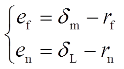
发电机功角控制目标为 ,负荷母线相角控制目标为
 ,则控制误差
 和
和 为
为
 (9)
(9)
取全局滑模控制的滑模面为
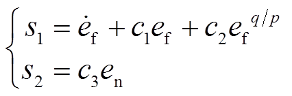 (10)
(10)
式中, ,
,  ,
,  ,随着其取值增加,控制器的可输出范围增大,但过大的取值会造成控制器输出波动较大,导致系统发生较大的抖振,和的取值参考文献[28];p和q为正奇数,p和q的取值应满足q<p<2q[29]。
为设计所需控制器,取 为
为
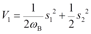 (11)
(11)
对求导可得
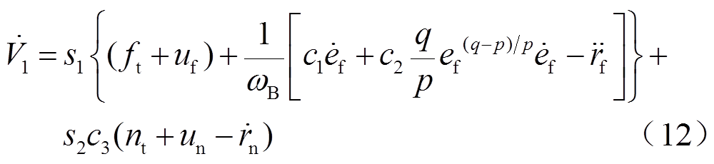
根据式(12),基于全局滑模扩张观测器的容错控制(Fault-Tolerant Control, FTC)表达式为
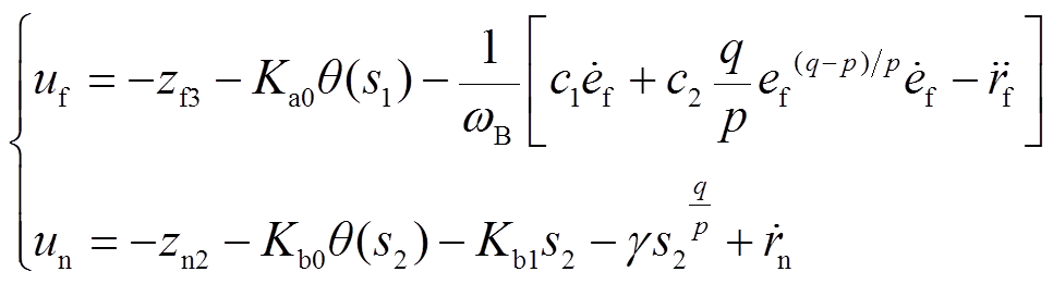 (13)
(13)
式中, 、
、 、
、 、
、 均为大于0的常数,其取值主要影响系统的抗扰动能力,取值越大,控制器的可输出范围越大,但在控制过程中系统的超调量就会越大。为兼顾收敛过程的动态特性,增加稳态收敛精度,各参数的取值不宜过大。
将式(13)代入式(12)中可得
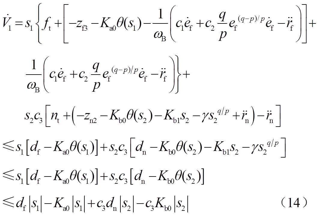
由于 ,
, ,,且
,,且 为偶数,式(14)可简化为
 (15)
(15)
若 ,
, ,根据
,根据 稳定性原理,
 成立,即系统各状态变量收敛至预定轨道,由此系统最终消除了混沌从而进入渐近稳定状态。
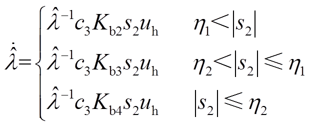
发电机端遭受各类扰动的概率较高,当扰动幅值与变化率较高时,对系统的影响尤为剧烈。此时,观测器的最终观测精度可能下降,进而引起控制器输出偏离理想值,系统收敛到稳定轨道的时间显著增加。针对发电机侧扰动问题,在控制器中采用固定增益与自适应增益相结合的方式。由此,基于全局滑模观测器的自适应容错控制的发电机侧控制器输出表达式为
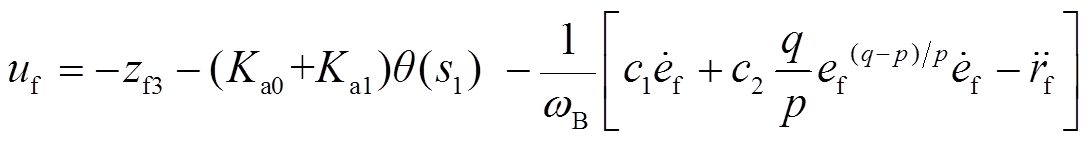 (16)
(16)
式中,与 分别为固定增益与自适应增益,并设计自适应增益表达式为
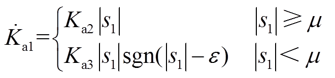 (17)
(17)
式中, 与
与 均为常数,并且满足
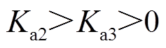 。为使被控系统具有较好的动态特性,与的取值不宜过大;
 为大于0的常数;
 为足够小的正数,其取值大小关系到系统的稳态收敛精度,其取值越小,系统的稳定轨道距离目标轨道越近。但控制器输出在收敛过程中存在切换现象,过小的和会使得开关函数sgn的输出反复切换,导致控制器输出反复跳变。
由式(17)可知,由于 ,当系统距离目标轨道较远,并且满足
 时,以较大的速度持续增大;至
 时刻后系统各状态变量距离目标轨道较近,并且满足
 时,以较小的速度增大;直至
 时刻后
时刻后 ,系统各状态变量接近目标轨道,此时
 ,之后缓慢减小。根据系统距离目标轨道的远近,自适应增益为控制器设置了不同的增长率,从而改善了系统收敛过程的动态特性。
为避免控制器 的输出过大,应对自适应增益进行限幅,限幅环节为
 (18)
(18)
为应对可能发生的控制器故障,应对负荷侧控制器的故障程度进行自适应估计,以补偿控制器故障对系统的影响。设 为的估计值,令
 ,首先选取如下候选Lyapunov函数
 。
。
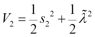 (19)
(19)
对求导可得
 (20)
(20)
将 代入后得
代入后得
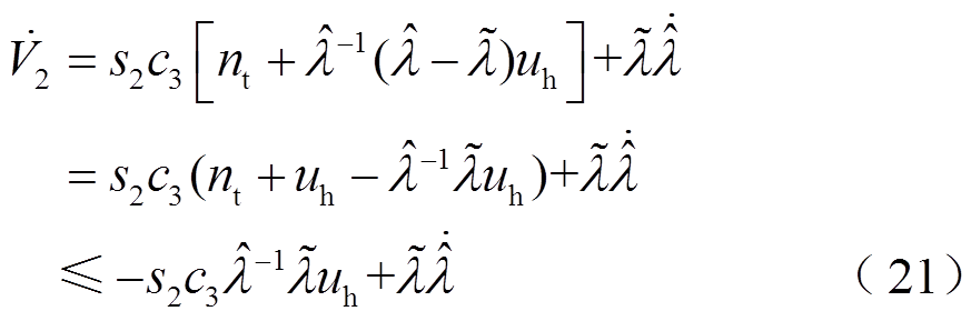
若要使 ,则
,则 应为
应为
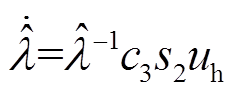 (22)
(22)
为改善负荷侧控制器的动态特性,提高控制器跟踪精度,将此自适应故障估计的表达式进行变换,变换结果为
 (23)
(23)
式中, 、
、 、
、 与
与 、
、 均为常数,且满足
 、
、 。为避免超调现象,根据各变量距离目标轨道的远近,为自适应率取不同的增益,避免控制器输出反复跳变,减少系统状态变量的抖振。
为避免控制器 输出过大,应对自适应故障估计进行限幅,限幅环节为
 (24)
(24)
结合式(13)和式(23)、式(24),基于全局滑模观测器的负荷侧容错控制器输出为
 (25)
(25)
重新选取Lyapunov函数 ,其表达式为
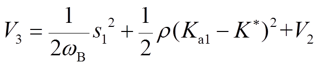 (26)
(26)
当系统状态变量逐渐接近预定轨道时,即当 时,对进行求导,其结果为
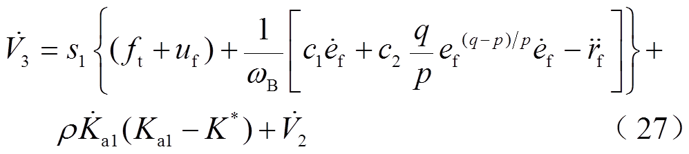
对式(27)进行化简后可得

进一步化简可得
 (29)
(29)
式(29)最终可简化为
 (30)
(30)
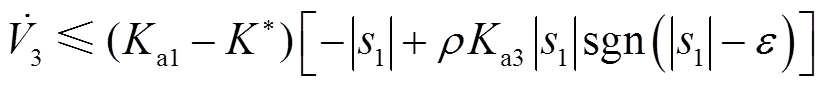
由于 是
是 的上界,即
的上界,即 ,当
,当 时,可能出现
 的情况,系统可能处于不稳定状态。此时,系统功角δm偏离目标轨道,
 随即迅速增大,当增大至超过
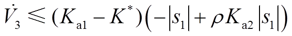
 时,即当
时,即当 时,若取控制器控制参数为
 ,则
,则 必定重新回到小于0的状态,系统最终趋于稳定。
当系统状态变量逐渐远离预定轨道时,即当 时,对进行求导,其求导结果为
 (31)
(31)
结合式(1)~式(31)综合可得,AFTC表达式为
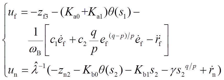 (32)
(32)
综上所述,在考虑外部扰动、传输故障和控制器输出故障的情况下,AFTC系统框图如图4所示。
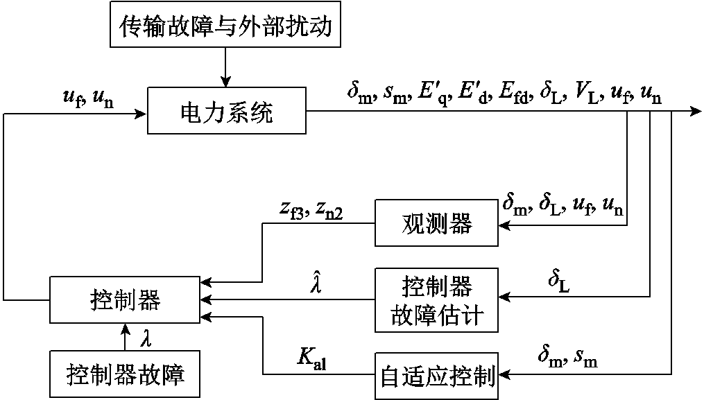
图4 基于全局滑模观测器的自适应容错控制系统框图
Fig.4 Block diagram of adaptive fault-tolerant control system based on global sliding mode observer
为比较第3节中所设计FTC与AFTC的控制效果,采用Matlab/Simulink进行仿真验证。首先取系统的分岔参数为: ,
, ,由第2节可知此时系统为混沌状态。取FTC的控制参数为:
 ,
, ,
, ,
, ,
, ,
, ,
, ,
, ,
, ,
, ,
, ,
, ,
, ,
, ,
, ,
, 。扩张观测器的输出初值
 、
、 、
、 、
、 、
、 均为0。发电机侧与负荷侧控制器输出初值和均为0。扩张观测器的输出与所观测的系统项、系统各状态变量与FTC控制器输出的时域图如图5所示。
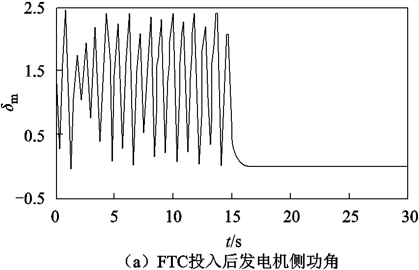

图5 FTC投入后系统状态时域图
Fig.5 Time domain diagram of system state after FTC input
由图5可知δm与δL在收敛到目标轨道的过程中并未发生大范围的波动,收敛过程相对平缓。由图5c可知,在FTC的作用下,系统各状态变量均收敛至固定轨道。由图5d可知,在FTC的作用下,扩张观测器的输出和在有限时间内逼近系统项 和
和 。
。
由第3节可知,FTC与AFTC均有一定的容错性来应对系统传输故障状态。除与FTC的相同参数外,取AFTC的控制参数为 ,
, ,
, ,
, ,
, ,
, ,
, ,
, ,
, ,
, ,
, ,
, ,
, 。自适应增益的初值为0,故障估计
 的初值为1。传输故障模型参数为
 ,
, ,
, ,
, ,即系统分别在30 s和40 s时发生传输故障,且输出信号幅值损失度为50%。
为对比所设计控制器对系统的控制效果,现引入文献[14]中的七阶电力系统动态滑模控制(Dynamic Sliding Mode Control, DSMC),DSMC、FTC与AFTC均在 时投入。系统状态时域图如图6a、图6b所示,发电机侧功角与负荷侧功角时域图如图6c、图6d所示。
由图6a可知,在 与
与 时分别在发电机侧与负荷侧发生传输故障后,DSMC控制下的δm立即偏离原目标轨道,并保持在偏离后的轨道上。由图6b可知,系统状态在AFTC的作用下只有短暂波动。由图6c可知,在DSMC的作用下,δm的现轨道与目标轨道的稳定偏差为0.04。而在FTC与AFTC的作用下,δm在偏离原轨道后迅速收敛至原目标轨道上,其目标轨道的最大偏差分别为0.022和0.009。由图6d可知,在DSMC的作用下,δL的现轨道与目标轨道的稳定偏差为-0.07。而在FTC与AFTC的作用下,δL在偏离原轨道后迅速收敛至原目标轨道上,其与目标轨道的最大偏差分别为-0.038和-0.037。
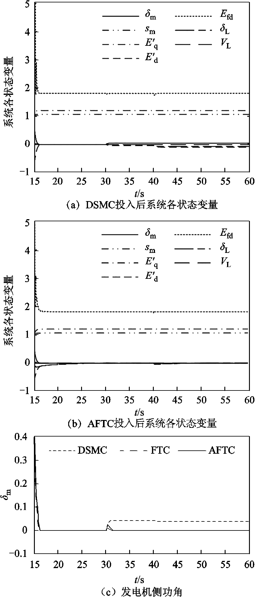
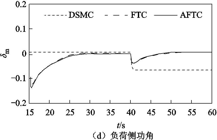
图6 传输故障下各控制器投入后系统状态时域图
Fig.6 Time domain diagram of system state under transmission fault
为对比系统在所设计控制器作用下的抗扰能力,当与时,在发电机侧加入两次幅值为0.5的功角状态量的阶跃扰动,发电机侧功角时域图如图7a所示。系统各状态变量时域图如图7b、图7c所示。
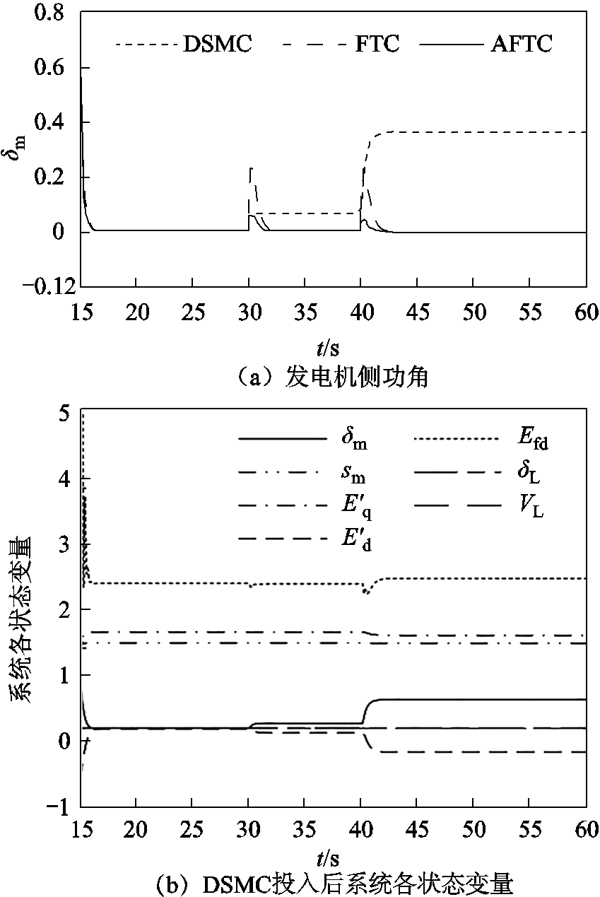
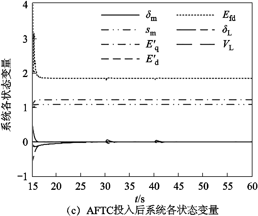
图7 阶跃扰动作用下各控制器投入后的系统状态时域图
Fig.7 Time domain diagram of system state after input of each controller under step disturbance
由图7a可知,在DSMC的作用下,δm在两次扰动后最终未能收敛至原轨道,两次扰动后δm对于目标轨道的稳定偏差分别为0.06和0.35。而在FTC与AFTC的作用下,δm在偏离原轨道后迅速收敛至原目标轨道上,在收敛过程中,与目标轨道的最大偏差分别为0.22和0.05。
由图7b可得,当发电机侧在t=30 s时第一次遭受阶跃扰动后,DSMC控制下的各状态变量立即偏离原目标轨道,并最终保持在扰动后的偏离轨道上;当发电机侧在t=40 s时第二次遭受阶跃扰动后,各状态变量在次发生偏移,并稳定在偏移后的轨道上。由图7c可知,在AFTC的控制作用下,当系统在上述两时刻遭受阶跃扰动后,各状态变量仅出现小幅波动,并很快收敛至原轨道。
为对比所设计控制器在故障情况下对系统的控制效果,取控制器故障数学模型的故障时间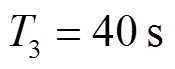 ,负荷侧控制器输出信号幅值按式(33)指数形式降低。
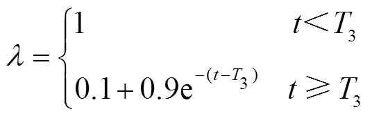 (33)
(33)
由式(33)可知,负荷侧控制器在时发生故障,输出信号以指数函数的形式进行衰减,当 时,
时, 最终衰减至
最终衰减至 。DSMC、FTC和AFTC均在
 时投入,系统各状态变量时域图如图8a、图8b所示,负荷侧功角时域图如图8c所示,各控制器输出时域图如图8d、图8f所示。
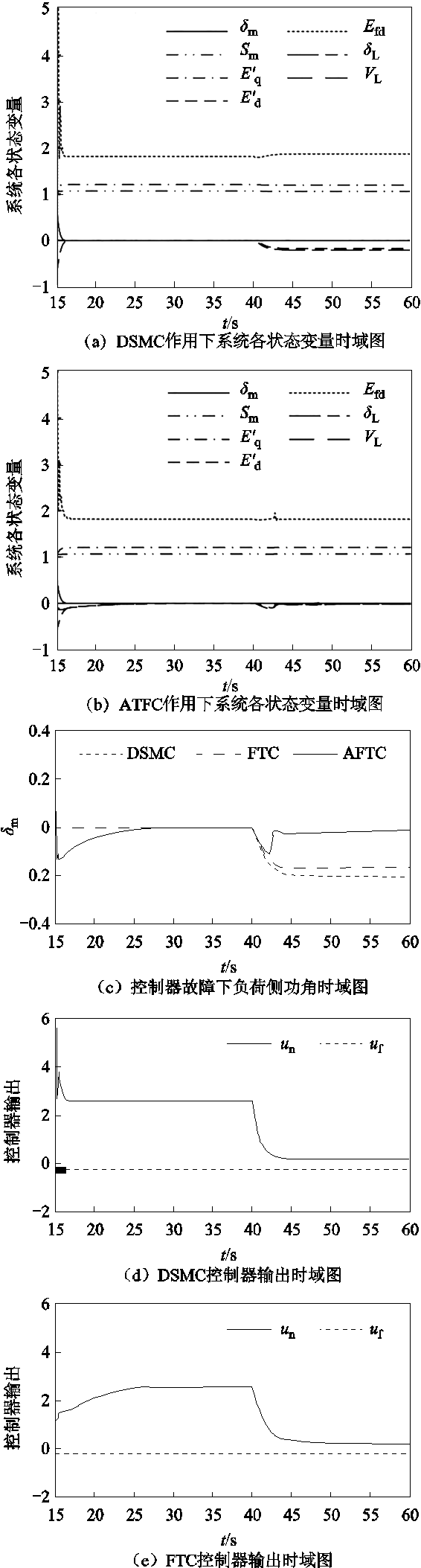
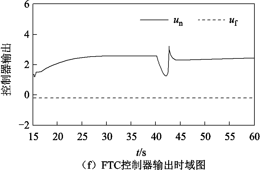
图8 控制器故障下各控制器投入后的系统状态时域图
Fig.8 Time domain diagram of system state after input of each controller under controller failure
由图8a可知,当负荷侧控制器在时发生控制器故障后,DSMC控制下的状态变量立即偏离原目标轨道,最终保持在某一固定轨道上。由图8b可知,在AFTC控制下,各状态变量仅在故障发生时刻有较小偏移。由图8c可知,在DSMC的作用下,δL在控制器故障后未能收敛至原轨道,δL对于目标轨道的稳定偏差为-0.20。在FTC的作用下,δL同样未能收敛至原轨道,δL对于目标轨道的稳定偏差为-0.16。在AFTC的作用下,δL短暂偏离了目标轨道,之后重新收敛至目标轨道附近,在系统收敛过程中,δL对于目标轨道的最大偏差为-0.11,稳定偏差为-0.013。
由图8d可知,当负荷侧控制器发生故障时,DSMC控制器输出信号幅值随之迅速下降,并最终稳定在约理想控制器输出的0.1倍处。由图8e可知,FTC控制器输出同样最终稳定在约理想控制器输出的0.1倍处。由图8f可知,由于自适应故障估计对控制器具有补偿作用,AFTC控制器输出信号幅值先短暂下降,继而随着自适应项的减小而增大,最终逐渐接近故障前的输出信号幅值。
1)根据七阶系统的自身特点,运用分岔图与相图对七阶系统进行混沌特性的分析,对系统关键参数变化下系统状态的变化情况进行了分析,得到系统在关键参数P0和Q0下的混沌特性。经过分析可知,当上述参数变化时,系统呈现出周期与混沌状态切换的现象。
2)对于七阶系统的控制问题,为减少控制器对于系统模型的依赖性,提出一种FTC策略。继而考虑发电机易遭受外部扰动,负荷侧控制器易遭受故障,为提高系统的容错能力,提出一种AFTC策略。仿真结果表明,所设计的控制器均能消除系统的混沌状态,而当系统分别遭受阶跃扰动、传输故障与控制器故障时,在AFTC的控制下,系统的最大偏移及稳态误差均较小。
3)对七阶系统来说,不能用传统的Wolf法求取Lyapunov指数,故目前七阶系统只能采用分岔图与相图相结合的方式进行混沌特性的分析。如何对Wolf法进行改进使其可以推广至七阶系统中,是今后需要关注的问题。
参考文献
[1] 赵光宙, 齐冬莲. 混沌控制理论及其应用[J]. 电工技术学报, 2001, 16(5): 77-82. Zhao Guangzhou, Qi Donglian. Chaotic control theory and applications[J]. Transactions of China Electrote-chnical Society, 2001, 16(5): 77-82.
[2] 王宝华, 杨成梧, 张强. 电力系统分岔与混沌研究综述[J]. 电工技术学报, 2005, 20(7): 1-10. Wang Baohua, Yang Chengwu, Zhang Qiang. Summary of bifurcation and chaos research in electric power system[J]. Transactions of China Electro-technical Society, 2005, 20(7): 1-10.
[3] Kumar A, Anwar M N, Kumar S. Sliding mode controller design for frequency regulation in an interconnected power system[J]. Protection and Control of Modern Power Systems, 2021, 6(1): 6.
[4] 许德智, 黄泊珉, 杨玮林. 神经网络自适应的永磁直线同步电机超扭曲终端滑模控制[J]. 电力系统保护与控制, 2021, 49(13): 64-71. Xu Dezhi, Huang Bomin, Yang Weilin. Neural network adaptive super twist terminal sliding mode control for a permanent magnet linear synchronous mtor[J]. Power System Protection and Control, 2021, 49(13): 64-71.
[5] 于永进, 王家斌, 王艳. 基于自适应全局滑模的电力系统混沌振荡控制[J]. 电力系统保护与控制, 2019, 47(16): 43-49. Yu Yongjin, Wang Jiabin, Wang Yan. Chaotic oscillation control in power system based on adaptive total sliding mode[J]. Power System Protection and Control, 2019, 47(16): 43-49.
[6] Ma Caoyuan, Wang Faxin, Li Zhijie, et al. Adaptive fixed-time fast terminal sliding mode control for chaotic oscillation in power system[J]. Mathematical Problems in Engineering, 2018, 2018: 1-10.
[7] 倪骏康, 刘崇新, 庞霞. 电力系统混沌振荡的等效快速终端模糊滑模控制[J]. 物理学报, 2013, 62(19): 190507. Ni Junkang, Liu Chongxin, Pang Xia. Fuzzy fast terminal sliding mode controller using an equivalent control for chaotic oscillation in power system[J]. Acta Physica Sinica, 2013, 62(19): 190507.
[8] 王家斌, 于永进, 阎振坤, 等. 基于自适应非奇异终端滑模控制的电力系统混沌抑制[J]. 电力系统保护与控制, 2021, 49(7): 120-126.Wang Jiabin, Yu Yongjin, Yan Zhenkun, et al. Chaotic suppression of a power system based on adaptive non-singular terminal sliding mode control[J]. Power System Protection and Control, 2021, 49(7): 120-126.
[9] 李小腾, 王江彬, 刘崇新, 等. 四阶混沌电力系统的全局快速滑模控制器设计[J]. 科学技术与工程, 2021, 21(24): 10298-10303. Li Xiaoteng, Wang Jiangbin, Liu Chongxin, et al. Global fast sliding mode controller design for a four-dimensional chaotic power system[J]. Science Technology and Engineering, 2021, 21(24): 10298-10303.
[10] Alrifai M T, Zribi M. Sliding mode control of chaos in a single machine connected to an infinite bus power system[J]. Mathematical Problems in Engineering, 2018, 2018: 1-13.
[11] 王江彬, 刘崇新. 4阶混沌电力系统的协同控制方法[J]. 西安交通大学学报, 2020, 54(1): 26-31. Wang Jiangbin, Liu Chongxin. Synergetic control method for four-dimensional chaotic power system[J]. Journal of Xi’an Jiaotong University, 2020, 54(1): 26-31.
[12] 杨洋, 于永进, 王云飞. 基于全局滑模时滞的电力系统混沌振荡控制[J]. 电力系统保护与控制, 2021, 49(15): 59-67. Yang Yang, Yu Yongjin, Wang Yunfei. Power system chaotic oscillation control based on global sliding mode time delay[J]. Power System Protection and Control, 2021, 49(15): 59-67.
[13] Yu Yixin, Jia Hongjie, Li Peng, et al. Power system instability and chaos[J]. Electric Power Systems Research, 2003, 65(3): 187-195.
[14] 王江彬, 刘凌, 刘崇新. 基于扩张状态观测器七阶混沌振荡电力系统的滑模变结构控制[J]. 电工技术学报, 2020, 35(21): 4524-4531. Wang Jiangbin, Liu Ling, Liu Chongxin. Sliding mode variable structure control for seven-dimensional chaotic power system based on extended state observer[J]. Transactions of China Electrotechnical Society, 2020, 35(21): 4524-4531.
[15] Wang Jiangbin, Liu Ling, Liu Chongxin, et al. Fixed-time synergetic control for a seven-dimensional chaotic power system model[J]. International Journal of Bifurcation and Chaos, 2019, 29(10): 1950130.
[16] Wang Jiangbin, Liu Ling, Liu Chongxin, et al. Adaptive sliding mode control based on equivalence principle and its application to chaos control in a seven-dimensional power system[J]. Mathematical Problems in Engineering, 2020, 2020: 1-13.
[17] Ni Junkang, Liu Ling, Liu Chongxin, et al. Chattering-free time scale separation sliding mode control design with application to power system chaos suppression[J]. Mathematical Problems in Engineering, 2016, 2016: 1-14.
[18] Rajesh K G, Padiyar K R. Bifurcation analysis of a three node power system with detailed models[J]. International Journal of Electrical Power & Energy Systems, 1999, 21(5): 375-393.
[19] Jia H J, Yu Y X, Li P. Relationship of power system chaos and instability modes[J]. Proceedings of the Chinese Society of Electrical Engineering, 2003, 23(2):1-4.
[20] Jia Hongjie, Yu Yixin, Li Peng, et al. Torus bifurcation and chaos in power systems[C]// Proceedings of International Conference on Power System Technology, Kunming, China, 2002: 1717-1722.
[21] 曹学谦, 葛琼璇, 朱进权, 等. 基于积分滑模的高速磁悬浮列车牵引控制策略[J]. 电工技术学报, 2022, 37(14): 3598-3607. Cao Xueqian, Ge Qiongxuan, Zhu Jinquan, et al. Traction-system research of high-speed maglev train based on integral sliding mode control[J]. Transactions of China Electrotechnical Society, 2022, 37(14): 3598-3607.
[22] 武志涛, 李帅, 程万胜. 基于扩展滑模扰动观测器的永磁直线同步电机定结构滑模位置跟踪控制[J]. 电工技术学报, 2022, 37(10): 2503-2512. Wu Zhitao, Li Shuai, Cheng Wansheng. Fixed structure sliding mode position tracking control for permanent magnet linear synchronous motor based on extended sliding mode disturbance observer[J]. Transactions of China Electrotechnical Society, 2022, 37(10): 2503-2512.
[23] 魏惠芳, 王丽梅. 永磁直线同步电机自适应模糊神经网络时变滑模控制[J]. 电工技术学报, 2022, 37(4): 861-869. Wei Huifang, Wang Limei. Adaptive fuzzy neural network time-varying sliding mode control for permanent magnet linear synchronous motor[J]. Transactions of China Electrotechnical Society, 2022, 37(4): 861-869.
[24] 张康, 王丽梅. 基于反馈线性化的永磁直线同步电机自适应动态滑模控制[J]. 电工技术学报, 2021, 36(19): 4016-4024. Zhang Kang, Wang Limei. Adaptive dynamic sliding mode control of permanent magnet linear synchronous motor based on feedback linearization[J]. Transactions of China Electrotechnical Society, 2021, 36(19): 4016-4024.
[25] 王勃, 王天擎, 于泳, 等. 感应电机电流环非线性积分滑模控制策略[J]. 电工技术学报, 2021, 36(10): 2039-2048.Wang Bo, Wang Tianqing, Yu Yong, et al. Nonlinear integral sliding mode control strategy for current loop of induction motor drives[J]. Transactions of China Electrotechnical Society, 2021, 36(10): 2039-2048.
[26] 杨挺, 张璐, 张亚健, 等. 基于信息熵计算模型的电力信息物理系统融合控制方法[J]. 电力系统自动化, 2021, 45(12): 65-74. Yang Ting, Zhang Lu, Zhang Yajian, et al. Fusion control method for cyber-physical power system based on information entropy calculation model[J]. Automation of Electric Power Systems, 2021, 45(12): 65-74.
[27] 韩京清. 自抗扰控制技术: 估计补偿不确定因素的控制技术[M]. 北京: 国防工业出版社, 2008: 197-198.
[28] Feng Y, Bao S, Yu X, Design method of non-singular terminal sliding mode control systems[J]. Control and Decision, 2002(02):194-198.
[29] 刘壮, 郑雪梅, 冯勇, 等. 全阶无抖振非奇异终端滑模控制方法[J]. 控制工程, 2020, 27(5): 824-829. Liu Zhuang, Zheng Xuemei, Feng Yong, et al. Full-order chattering free non-singular terminal sliding mode control method[J]. Control Engineering of China, 2020, 27(5): 824-829.
Abstract When the power system suffers from external disturbance or the parameters change in a certain range, the power Angle of the system may appear disordered oscillation in a certain range, that is, the system enters a chaotic state. At present, in order to suppress the chaotic state of power system, controllers using various principles have been designed, but the disturbance and controller failure are rarely considered in the design process. To solve this problem, this paper proposes an adaptive fault-tolerant control strategy based on global sliding mode, which makes the system more stable under the action of the controller.
Firstly, according to the characteristics of the seven-dimensional system, the dynamic characteristics of the system under the change of key parameters P0 and Q0 are obtained by using the bifurcation diagram and phase diagram. After analysis, it can be seen that when P0 changes from small to large, the system presents a transition phenomenon from periodic to chaotic state, and when Q0 changes from small to large, the system presents a transition phenomenon from chaotic to periodic state. Through the analysis of chaotic characteristics, the chaotic state parameters of the system are obtained.
Secondly, in order to solve the problem that the controller could not timely obtain the changes of system items due to the disturbance, an observer was designed to observe the operation characteristics of the synchronous generator rotor and input the observation results to the input end of the controller. This paper proposes a Fault-tolerant control (FTC) strategy based on global sliding mode extended observer. In order to further reduce the fluctuation of the system under the disturbance and consider the possible failure, the method of combining fixed gain and adaptive gain is adopted in the controller. A strategy of adaptive fault-tolerant control (AFTC) based on global sliding mode observer is proposed.
The simulation results show that, under the action of FTC, the state variables of the system converge to the fixed orbit, and the output of the extended observer approximates the system term in finite time. When the system suffers from transmission faults, the stable deviations of δm and δL from the current orbit and the target orbit are 0.04 and -0.07 under the action of DSMC. Under the action of FTC and AFTC, the maximum deviation of δm and δL from the target orbit is 0.022 and 0.009, and -0.038 and -0.037, respectively. When the system is subjected to step perturbation, under the action of DSMC, the stability deviation of δm to the target orbit after two perturbations is 0.06 and 0.35, respectively. Under the action of FTC and AFTC, δm rapidly converges to the original target orbit after deviating from the original orbit, and the maximum deviation from the target orbit is 0.22 and 0.05, respectively. When the system suffers from controller failure, the stability deviation of δL to the target orbit is -0.20 under the action of DSMC. Under the action of FTC, the stability deviation of δL to the target orbit is -0.16. Under the action of AFTC, δL converges to the vicinity of the target orbit again, and the maximum deviation of δL to the target orbit is -0.11, and the stability deviation is -0.013.
By analyzing the simulation results, it can be found that all the designed controllers can eliminate the chaotic state of the system, and when the system is subjected to step disturbance, transmission fault and controller fault, the maximum offset and steady-state error of the system are small under the control of AFTC.
Keywords: Power system, chaos, global sliding mode, adaptive, extended state observer
DOI:10.19595/j.cnki.1000-6753.tces.221660
中图分类号:TM712
国家自然科学基金资助项目(61803233)。
收稿日期 2022-08-30
改稿日期 2022-10-18
于永进 男,1980年生,副教授,硕士生导师,研究方向为电力系统运行与控制。E-mail:yaydjto@ 163.com
杨 洋 男,1995年生,硕士,研究方向电力系统运行与控制。E-mail:2534019091@qq.com(通信作者)
(编辑 赫蕾)