 (1)
(1)
摘要 常规的永磁同步电机全速域无位置传感器控制通过复合两种位置观测器实现全速域的转子位置估计,然而,在电机频繁宽频域调速工况下,两种位置观测器频繁地切换,易导致估计的位置和转速振荡,并且两种位置估计方法需要单独的设计和调谐,增加了系统整定难度和算法复杂度。为此,该文提出了一种基于共振扩张状态观测器的内置式永磁同步电机统一全速域无位置传感器控制方法。首先,通过共振扩张状态观测器估计基频反电动势和高频反电动势。然后,建立了统一全速域模型,通过统一全速域模型实现全速域的转子位置和转速估计。在零速和低速时,通过向d轴注入高频电压,增加统一全速域模型中转子位置信息的信噪比,从而可以准确估计零速和低速区的转子位置,消除了传统高频注入法中由滤波器和延迟引起的估计误差。当电机在中高速区运行时,统一全速域模型自动蜕变为基频模型法,不需要两种位置观测器切换控制。最后,在2.0 kW内置式永磁同步电机实验平台上验证了算法的有效性。
关键词:永磁同步电机 无位置传感器控制 共振扩张状态观测器 统一全速域模型
我国在燃油车的发动机和变速箱等方面存在技术代差及专利壁垒,汽车市场长期被外企、合资车瓜分,国产占比低,且处于市场低端。在“双碳”目标下,电动汽车发展正面临前所未有的机遇,我国电动汽车有望实现弯道超车。电机驱动系统作为电动汽车的核心部件,对电动汽车的运行性能至关重要。在众多的电机类型中,内置式永磁同步电机(Interior Permanent Magnet Synchronous Motor, IPMSM)由于效率高、功率密度高等优点在电动汽车中得到广泛的应用[1]。IPMSM无位置传感器控制不但能增加电机驱动系统的可靠性,而且可以降低系统的成本[2],不断提高无位置传感器IPMSM驱动系统的性能,从而可以提高我国电动汽车的竞争力和对恶劣环境的适应性。
目前,IPMSM无位置传感器控制可以分为两类:基于电机基频模型的方法和基于电机凸极特性的方法[3]。基于电机基频模型的无位置传感器控制方法通过反电动势或磁链估计转子位置和转速。基于电机基频模型的方法主要包括滑模观测器[4]、扩张状态观测器(Extended State Observer, ESO)[5]、卡尔曼滤波器[6]、全阶自适应观测器[7]、磁链观测器[8]等。由于反电动势的幅值和转速成正比,磁链是反电动势的积分。当IPMSM在高速区运行时,基于电机基频模型的方法可以准确估计位置和转速。此外,通过将自适应滤波器和观测器相结合,可以减少逆变器非线性和扰动等非理想因素的影 响[9]。在零速和低速时,由于反电动势信噪比低,基于电机基频模型的方法难以准确估计转子位置和转速。相反,基于电机凸极特性的方法不依赖基频反电动势,通过跟踪转子的凸极特性估计转子的位置和转速[10]。基于电机凸极特性的方法包括高频信号注入法[11]、低频信号注入法[12]、电流微分法[13]、脉冲宽度调制(Pulse Width Modulation, PWM)载波频率成分法[14]等,其中高频信号注入法注入的高频信号响应易于和电机基频信号分离,并且转子位置信息信噪比大,在零速和低速可以准确估计转子的位置和转速,从而获得了广泛的研究和应用。高频信号注入通常可分为正弦波注入[15]、方波注入[16]和随机注入[17]。这三种信号各有优势,高频正弦注入法对失真如逆变器非线性、参数变化等更具鲁棒性[18];将方波注入法的注入频率提高到开关频率,可以消除信号解调过程中的数字滤波器并提高控制带宽[19];随机注入法通过多信号注入达到扩展高频电流功率谱密度的目的,从而降低高频注入法产生的可听噪声[20]。不同的注入方案可以满足不同的应用要求,但它们需要不同的信号解调技术。
然而,基于高频注入的IPMSM无位置传感器控制方法有一些负面影响,如损耗增加、转矩波动、产生刺耳可听噪声等[21-22]。此外,在电机高速运行时,逆变器的最大输出电压限制额外信号的注入。因此,高频注入法一般仅在电机运行在低速和零速时估计转子的位置[23-24]。同时,在零速和低速时,由于反电动势信噪比低,基于电机基频模型的方法难以准确地估计转子位置和转速。为实现包括静止起动状态在内的全速域转子位置的有效观测,通常在静止和低速区采用高频信号注入法,而在中高速区采用电机基频模型法[25-26]。因而,从低速到高速的无位置传感器控制需要对两种位置估计方法进行切换控制。切换控制方法主要有滞环切换法、转速或位置加权法和位置误差加权法[27]。然而,传统的全速无位置传感器方法涉及在不同转速下具有不同结构的两种位置估计方法,这两种位置估计方法需要单独的设计和调谐,增加了系统整定难度和算法复杂度,并且在电机频繁宽频域调速工况下,两种位置估计方法频繁地相互切换,容易导致估计的位置和转速振荡。如果无位置传感器控制方法可以在全速域采用一种方法估计转子位置和转速,那么对工业应用来说将更具吸引力。
本文提出了一种基于共振ESO的IPMSM统一全速域无位置传感器控制方法。首先,通过共振ESO估计基频反电动势和高频反电动势。然后,建立全速域的统一模型,通过统一模型实现全速域的转子位置和转速估计,不需要两种估计方法切换控制。在零速和低速时,通过向d轴注入高频电压,增加统一模型中转子位置信息的信噪比,从而可以准确估计零速和低速区的转子位置,消除传统高频注入方法中由滤波器和延迟引起的估计误差。当电机在中高速区运行时,由于统一模型中转子位置信息信噪比大,不需要注入高频信号,统一模型自动蜕变为基频模型法,不需要切换控制。因此,所提出的方法可以通过相同的估计器实现全速域转子位置估计,与传统的全速域估计方法相比,简化了控制算法,减少了调谐工作量,并且可以提高位置观测精度。
由于反电动势幅值与转子转速成正比,当IPMSM运行在低速时,基于电机基频模型方法难以准确估计转子位置。而基于IPMSM转子凸极特性的高频信号注入法不依赖反电动势的大小,可以在零速和低速区估计转子的位置。因此,传统的IPMSM全速域无传感器控制采用复合适合低速区的高频信号注入法和适合中高速区的电机基频模型法估计全速域的转子位置。
根据注入信号位置的不同,高频信号注入分为高频旋转信号注入法和高频脉振注入法。根据注入信号波形的不同,高频信号注入法分为高频正弦注入法和高频方波注入法。本文以高频脉振正弦电压注入法为例进行分析。
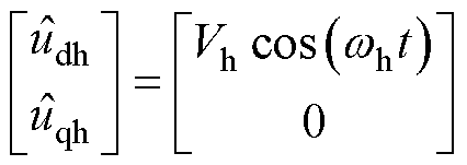
高频正弦电压注入到估计的同步坐标系de轴,注入的脉振电压为
 (1)
(1)
式中, 和
和 分别为注入de轴和qe轴的高频电压;Vh为注入高频电压的振幅;wh为注入高频电压的角频率。
当IPMSM在零速和低速区运行时,由于注入电压的频率远远高于电机运行的频率,则IPMSM电压方程中的定子电阻压降和反电动势可以忽略,在 轴电压方程为
 (2)
(2)
其中


式中, 、
、 、
、 、
、 分别为
分别为 轴和
轴和 轴的定子电压和定子电流;Ld和Lq分别为d轴和q轴电感;
 为实际转子位置;p为微分算子。
根据式(1)和式(2),高频电流响应为
 (3)
(3)
其中

式中, 和
和 分别为de轴和qe轴的高频电流响应;
 为估计的转子位置。
解调 得到转子位置误差信号为
 (4)
(4)
式中, 为转子位置误差
 的函数,将
的函数,将 作为锁相环(Phase-Locked Loop, PLL)的输入,PLL的输出为估计的转子位置和转速;LPF为低通滤波器。
基于电机基频模型的中高速转子位置估计方法通常利用反电动势或磁链中包含的转子位置信息估计转子位置,本文以基于反电动势估计转子位置为例进行分析。IPMSM在 轴电压方程为
 (5)
(5)
 (6)
(6)
式中, 和
和 分别为
分别为 轴和
轴和 轴扩展反电动势;Rs为定子电阻;
 为实际转子角频率;
 为永磁体磁链;id和iq分别为d轴和q轴的定子电流。
采用ESO、滑模观测器等基于式(5)构建状态方程可以估计扩展反电动势,估计的扩展反电动势通过反正切或PLL估计中高速区的转子位置。
由于IPMSM在低速区和中高速区采用不同的位置估计方法,因此转子位置误差的形式不同。需要为不同的方法设计不同的PLL,这给控制带来了复杂性。图1为通常采用的基于转速和位置加权的过渡区过渡策略。图1中, 和
和 分别为高频信号注入法估计的转子位置和转速,
 和
和 分别为基频模型法估计的转子位置和转速,
 、
、 分别为过渡区的下限和上限。在过渡区,用于闭环的转子位置和转速是两种方法估计的结果通过加权获得的。
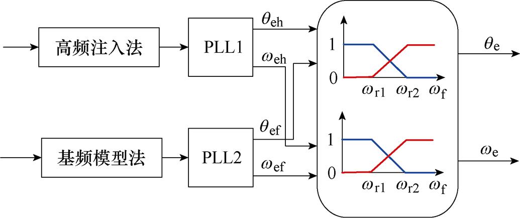
图1 基于转速和位置加权的过渡区过渡策略
Fig.1 Transition zone transition strategy based on speed and position weighting
传统全速域无位置传感器控制方法需要设计两套独立的转子位置估计方法,增加了算法的复杂性和调谐难度,同时由于系统延时和滤波器会引起高频注入法估计转子位置误差。此外,在快速起动时,两套转子位置估计方法估计的转子位置和转速难以同步,极易导致过渡区转子位置和转速振荡。
IPMSM在 轴以扩展磁链表示的电压方程为
 (7)
(7)
 (8)
(8)
式中, 为扩展磁链振幅,
 ;p(id)为id的微分。
式(8)右侧第一项的振幅与转子转速成正比,因此可以采用这一项估计中高速区的转子位置。要保证全速域转子位置相关信号的信噪比,可以利用式(8)右侧的第二项,只要保证低速区定子电流id导数的大小满足信噪比,就可以估计全速域的转子位置。在de轴注入高频电压信号时,根据式(3),当 时,定子电流id中包含的高频电流
 的导数为
的导数为
 (9)
(9)
相比高频电流的导数,基频定子电流导数可以忽略,则当注入高频电压后,式(8)可以表示为
 (10)
(10)
根据式(10),注入高频电压后,可以保证全速域的转子位置信号信噪比,进而可以估计全速域的转子位置。
ESO不依赖被控对象的精确数学模型,本文采用ESO估计式(7)中的反电动势 和
和 。由式(10)可知,注入高频电压后,
 和
和 中包含以电机运行频率变化的基频分量和以注入电压频率变化的高频分量。由于ESO具有低通滤波器性质,当设计为高带宽时,ESO对高频噪声的抑制能力变弱,致使估计的转子位置和转速稳态精度变差;当设计为低带宽时,ESO虽然可以有效抑制测量噪声,但估计的
 和
和 的高频分量相位滞后和幅值衰减严重,导致低速区转子位置信息不能准确反映实际的转子位置,进而导致低速区估计的转子位置和转速不准确。
本文提出共振ESO估计反电动势 和
和 ,共振ESO在传统的ESO的估计环路中植入高频扰动估计环路,估计由注入高频电压产生的低速区高频反电动势分量,基频反电动势分量由ESO本来的扰动估计环路估计。图2为本文提出的基于共振ESO的IPMSM统一全速域无位置传感器控制结构框图。
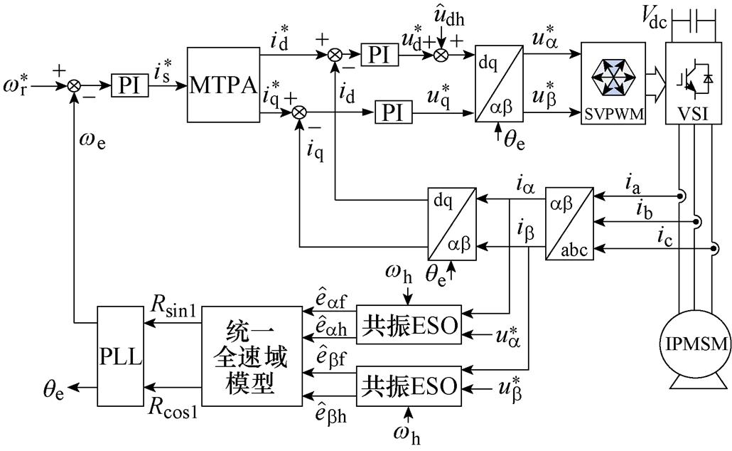
图2 所提出的基于共振ESO的IPMSM统一全速域无位置传感器控制结构框图
Fig.2 The proposed IPMSM unified full speed sensorless control structure diagram based on resonance ESO
为了降低IPMSM驱动系统的成本,用指令电压代替实际定子电压。共振ESO的输入是 轴指令电压、定子电流以及高频注入电压的角频率,输出是式(10)中反电动势的基频分量和高频分量,其中,
 ,
, ,
, ,
, 。共振ESO估计的反电动势作为统一全速域模型模块的输入,统一全速域模型模块输出为转子位置信息Rsin1和Rcos1;Rsin1和Rcos1作为PLL的输入,PLL的输出为估计的转子位置qe和转速we。
式(7)重写为
 (11)
(11)
基于ESO原理,将式(11)中右侧最后一项当作干扰,构建状态方程为
 (12)
(12)
其中
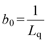
 =
=
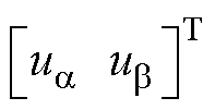
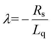
 =
=
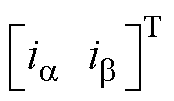
 =
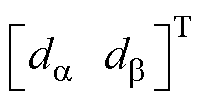
=


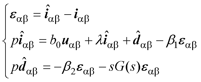
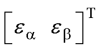
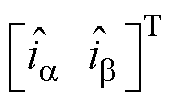
根据式(12),设计的共振ESO为
 (13)
(13)
其中
 =
=
 =
=
 =
=

 =
=

 =
=
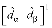
式中, 和
和 分别为共振ESO估计的
 、
、 轴定子电流;
 和
和 分别为
分别为 和
和 的估计值;b1和b2为可调参数;G(s)为植入的高频扰动估计环路,可以表示为
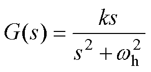 (14)
(14)
式中,k为可调参数。
图3为共振ESO的结构框图, =
=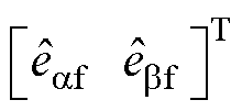 ,
, 和
和 分别为
分别为 和
和 的估计值,
的估计值, =
=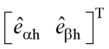 ,
, 和
和 分别为
分别为 和
和 的估计值。
的估计值。
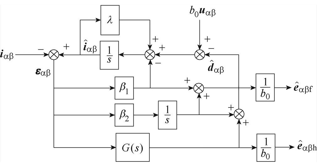
图3 共振ESO的结构框图
Fig.3 Structural block diagram of resonance ESO
通过式(13)估计 轴扰动
轴扰动 和估计
和估计 轴扰动
轴扰动 的结构相同,则下文以
 轴为例分析估计扰动
 和实际
和实际 的传递函数。根据式(12)和式(13),
 相对于
相对于 的传递函数为
 (15)
(15)
由图3和式(15)可得,估计的 轴基频反电动势
 为
为

 (16)
(16)
根据式(16)可得 对于
对于 的传递函数为
 (17)
(17)
由图3和式(15)可得,估计的 轴高频反电动势
 为
为

 (18)
(18)
根据式(18)可得 对于
对于 的传递函数为
 (19)
(19)
当G(s)=0时,将式(15)特征多项式以带宽的形式表示为
 (20)
(20)
式中, 为ESO的带宽。根据式(20)可得,
 ,
, 。同时考虑共振ESO估计扰动的准确性和抑制测量噪声性能,本文取
 =2 000 rad/s。可调参数k越大对中心频率的鲁棒性越强,但选频特性变弱,综合考虑这两方面的影响,本文取k=100b2。
图4为 对于
对于 的传递函数的Bode图。图5为
 对于
对于 的传递函数的Bode图。考虑注入高频电压角频率wh=500×2p rad/s,结合式(10),从图4中可以看出,共振ESO的输出
 可以估计低频扰动,并且在高频注入频率处具有陷波器特性,此外对测量高频噪声具有良好的抑制能力,因此,共振ESO的输出
 可以准确提取式(10)中右侧第一项基频反电动势。从图5中可以看出,共振ESO的输出
 在高频注入频率处没有幅值衰减和相位滞后,并且对低频信号和测量噪声具有良好的抑制能力,因此,共振ESO的输出
 可以准确提取式(10)中右侧第二项高频反电动势。
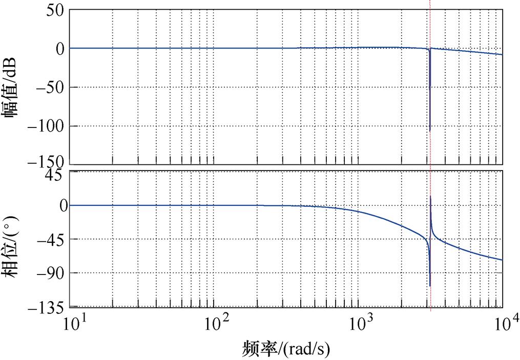
图4  对于
对于 的传递函数的Bode图
Fig.4 Bode of transfer function 
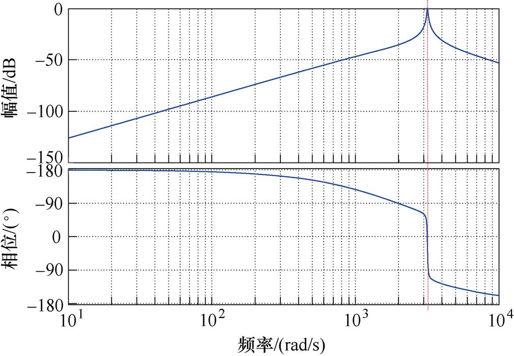
图5  对于
对于 的传递函数的Bode图
Fig.5 Bode of transfer function 
共振ESO估计的 =
= ,
, =
= ,
, =
= ,
, =
= 。虽然高频反电动势
 和
和 包含转子位置信息,但是受到注入高频信号的调制,不能直接用来估计转子位置。基频反电动势
 和
和 虽然是转子位置的函数,但是在低速区由于幅值小,不能准确估计转子位置。为了构建满足全速域的统一转子位置信息,构建虚拟反电动势为
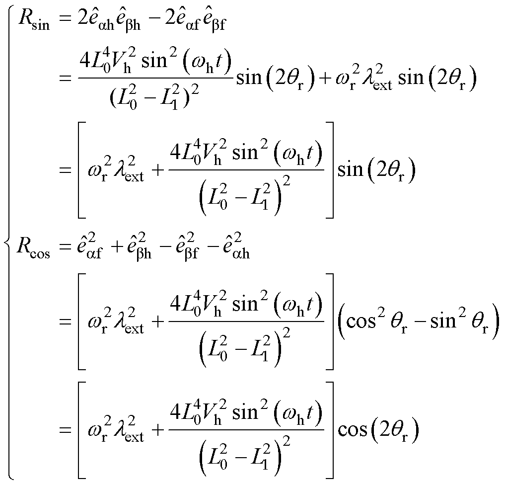 (21)
(21)
式中,Rsin和Rcos为构建的虚拟反电动势。
从式(21)可以看出,Rsin和Rcos为转子位置的函数,并且Rsin和Rcos的幅值是基频反电动势幅值的二次方与高频反电动势幅值的二次方的和,因此可以保证全速域的转子位置信息的信噪比。由于Rsin和Rcos的振幅随转速变化,为了方便设计PLL参数,采用归一化方法将Rsin和Rcos的振幅归一化为1。为了防止归一化过程中零的除法,首先对Rsin和Rcos进行低通滤波,需要指出的是,设计的低通滤波器截止频率高,引起Rsin和Rcos中转子位置信息相位的滞后可以忽略不计。对Rsin和Rcos进行低通滤波为
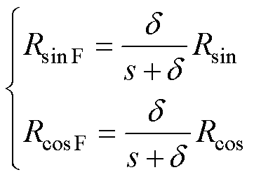 (22)
(22)
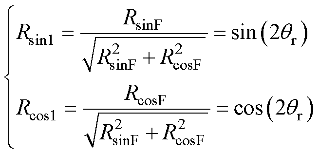
式中,RsinF和RcosF分别为对Rsin和Rcos进行低通滤波后的值; 为低通滤波器的截止频率。将RsinF和RcosF的振幅归一化,有
 (23)
(23)
式中,Rsin1和Rcos1分别为转子位置的正弦函数和余弦函数,将Rsin1和Rcos1输入到PLL,可以估计全速域的转子位置和转速。构建的统一全速域转子位置信息框图如图6所示。
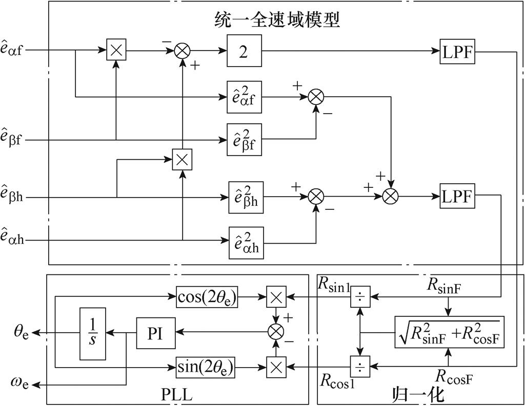
图6 构建的统一全速域转子位置信息框图
Fig.6 Constructed unified full speed domain rotor position information block diagram
为了验证所提出的基于共振ESO的统一全速域无位置传感器控制方法的正确性和有效性,在如图7所示的2.0 kW IPMSM实验平台上进行了实验验证,2.0 kW IPMSM的参数见表1。PWM开关频率为8 kHz,注入高频电压为 。为了评估所提出方法估计转子位置和转速的准确性,在测试IPMSM的尾端安转了旋转变压器,旋转变压器检测的转速和转子位置只用来评估所提出方法的准确性,不参与闭环控制。
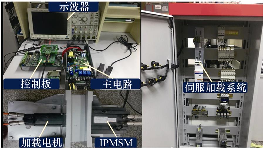
图7 2.0 kW IPMSM实验平台
Fig.7 2.0 kW IPMSM experimental platform
图8为电机在75 r/min(5 Hz)空载稳态运行时,所提出的基于共振ESO的统一全速域方法提取转子位置信息的实验结果。其中,图8a为共振ESO估计的基频反电动势和高频反电动势波形,图8b为估计的 轴高频反电动势
 快速傅里叶变换(Fast Fourier Transform,FFT)分析,图8c为构建的统一全速域模型获得的转子位置信息归一化后的实验波形。从图8a可以看出,所提出的共振ESO可以分别估计基频反电动势和高频反电动势。由图8b可以看出,估计的
 轴高频反电动势
 的频率为500 Hz,与注入高频电压的频率一样(注入高频正弦电压的频率为500 Hz),共振ESO的谐振频率选择注入高频电压的频率。从图8c可以看出,构建的统一全速域模型提取的转子位置信息是2倍转子位置的正弦和余弦函数,与理论分析一致,表明了所提出的基于共振ESO的统一全速域方法的正确性。
表1 测试电机参数
Tab.1 Parameters of testing motor

参 数数 值 额定功率/kW2 额定电压/V380 额定电流/A5.8 额定转速/(r/min)1 000 极数8 额定转矩/(N·m)19 电阻/W1.351 d轴电感/mH10.85 q轴电感/mH25.52 额定频率/Hz66.67
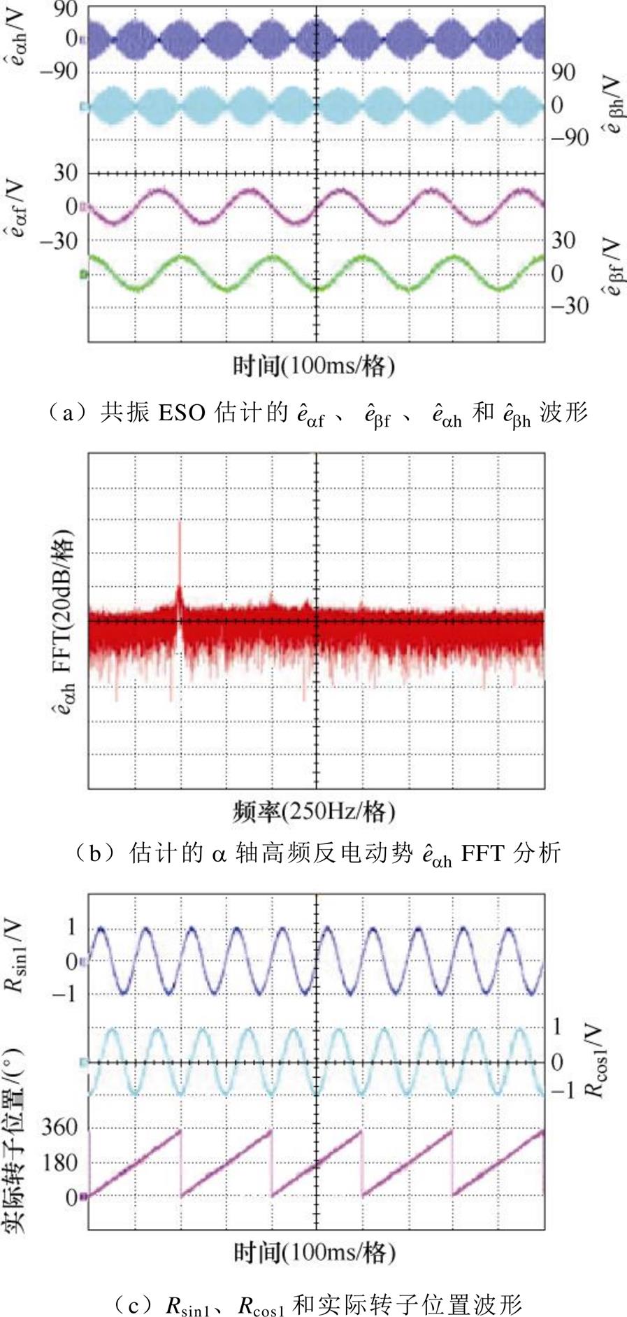
图8 统一全速域方法转子位置信息提取过程实验结果
Fig.8 Experimental results of the extraction process of rotor position information using unified full speed domain method
图9和图10的实验条件为,电机首先在0 r/min运行,其次从0 r/min快速加速到1 000 r/min,接着电机在1 000 r/min运行,然后从1 000 r/min快速减速到0 r/min,最后电机在0 r/min运行。图9为空载加减速实验结果,图10为带额定负载加减速实验结果。图9a和图10a为传统的复合控制全速域方法实验结果。传统的复合控制全速域方法中低速采用高频脉振正弦电压注入法,注入的高频电压的振幅和频率与所提出的统一全速域方法一致;中高速采用的是ESO,过渡策略采用转速和位置加权方法,过渡区间为[10 Hz, 15 Hz]。对比两种全速域方法可以看出,复合控制全速域方法低速区和高速区采用两种观测器,位置误差和转速误差明显不一样,并且在过渡区位置误差和转速误差较大。从图9a和图10a可以看出,复合控制全速域方法在空载加减速过程中最大转速误差和位置误差分别为11.7 r/min和12.4°,在额定负载加减速过程中最大转速误差和位置误差分别为12 r/min和12.8°。然而,所提出的统一全速域方法全速域采用一种方法,由于没有过渡区,位置误差和转速误差没有明显的变化,并且在低速区消除了传统高频注入方法中由滤波器和延迟引起的估计误差。从图9b和图10b可以看出,所提出的方法在空载加减速过程中最大转速误差和位置误差分别为5 r/min和7°,在额定负载加减速过程中最大转速误差和位置误差分别为8 r/min和8.5°,相比复合控制全速域方法,所提出的统一全速域方法在低速区和过渡区转子位置误差和转速误差更小。
图11为额定转速1 000 r/min突加减额定负载对比实验结果,其中,图11a和图11b分别为传统复合控制全速域方法和所提出的统一全速域方法。在高速区,统一全速域模型自动蜕变为ESO,复合控制全速域方法在高速区也只采用ESO,对比图11a和图11b可以看出,传统复合控制全速域方法突加减额定负载最大转速误差和位置误差分别为10 r/min和10.3°,统一全速域方法突加减额定负载最大转速误差和位置误差分别为9.7 r/min和10°,两种方法在高速区估计性能类似。
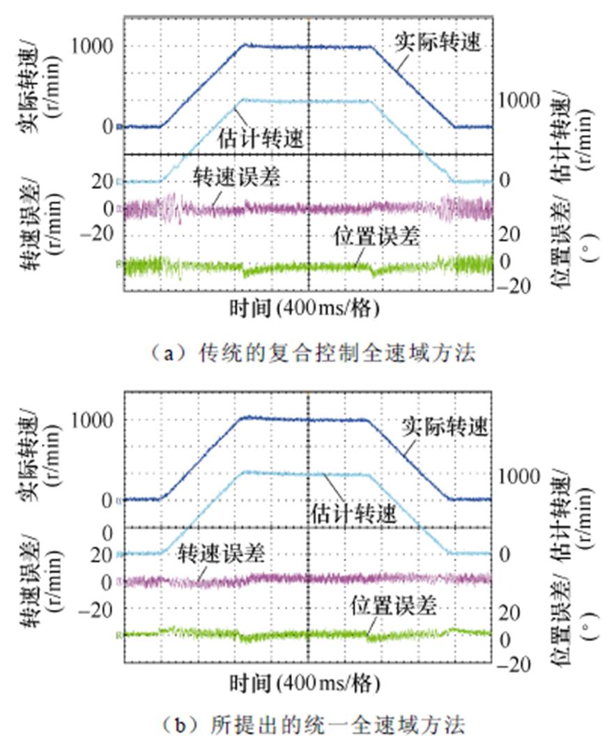
图9 空载加减速对比实验结果
Fig.9 Experimental results at the acceleration and deceleration with no load
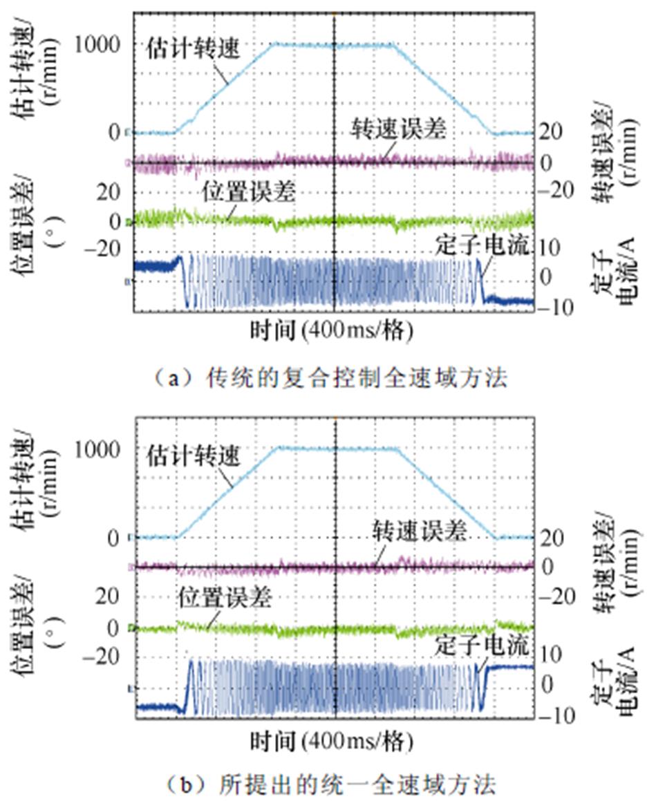
图10 额定负载加减速对比实验结果
Fig.10 Experimental results at the acceleration and deceleration with rated load
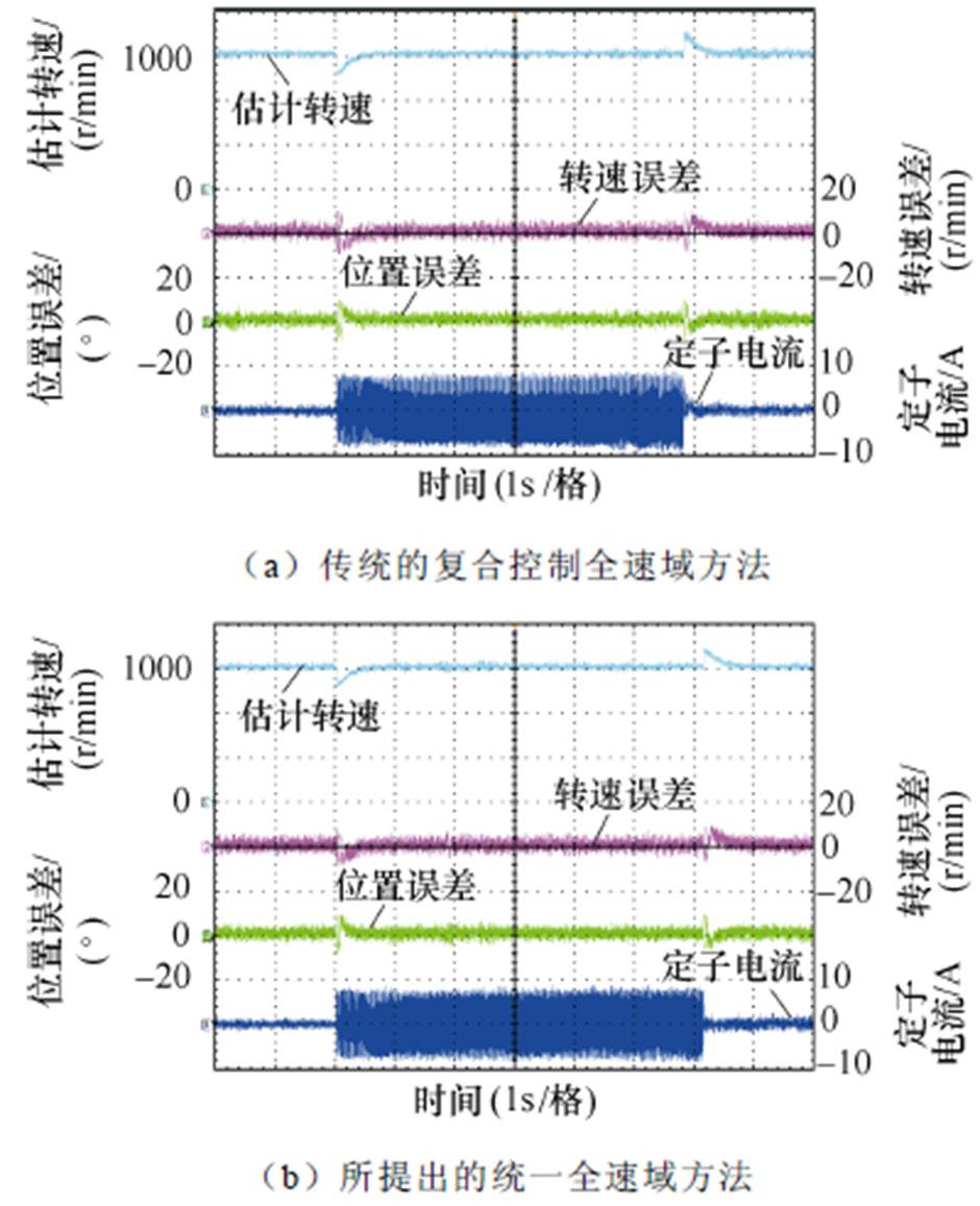
图11 1 000 r/min突加减额定负载对比实验结果
Fig.11 Comparative experimental results with rated load at 1 000 r/min
图12为200 r/min突加减额定负载对比实验结果。其中,图12a和图12b分别为传统复合控制全速域方法和所提出的统一全速域方法。200 r/min(13.33 Hz)在传统复合控制全速域方法过渡区内,闭环转子位置和转速由复合的两种方法加权得到,由图12a可以看出,突加减额定负载时最大转速误差和位置误差分别为15.8 r/min和13.5°。然而,所提出的统一全速域方法没有过渡区,突加减额定负载时最大转速误差和位置误差分别为8.5 r/min和9.2°。对比实验结果可以看出,与传统复合控制全速域方法相比,所提出的方法在200 r/min突加减额定负载时转子位置误差和转速误差更小。

图12 200 r/min突加减额定负载对比实验结果
Fig.12 Comparative experimental results with rated load at 200 r/min
图13为0 r/min突加减额定负载对比实验结果。其中,图13a和图13b分别为传统复合控制全速域方法和所提出的统一全速域方法。由于所提出的方法在低速区消除了传统高频注入方法中由滤波器和延迟引起的估计误差,对比实验结果可以看出,传统复合控制全速域方法突加减额定负载最大转速误差和位置误差分别为16 r/min和12.2°,统一全速域方法突加减额定负载最大转速误差和位置误差分别为9.8 r/min和8.2°。因此,所提出的方法在0 r/min突加减额定负载运行时具有更好的观测性能。
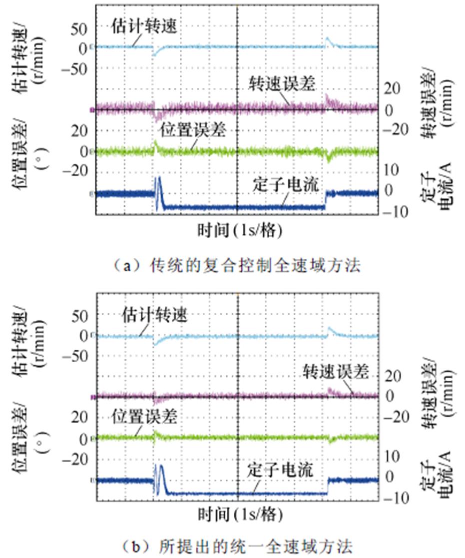
图13 0 r/min突加减额定负载对比实验结果
Fig.13 Comparative experimental results with rated load at 0 r/min
图14为额定负载条件下设定转速分别为0、75、150、45和0 r/min时,传统复合控制全速域方法和所提出的统一全速域方法的对比实验结果。由于运行转速低于过渡区下限,传统复合控制全速域方法仅高频注入法估计的转子位置和转速进行闭环控制,从图14a可以看出,传统复合控制全速域方法最大转速误差和位置误差分别为14.2 r/min和13.1°。然而,所提出的统一全速域方法不需要提取高频电流和高频电流解调过程,消除了传统高频注入方法中由滤波器和延迟引起的估计误差,由图14b可以看出,所提出的统一全速域方法转速误差和位置误差分别在7 r/min和7°之内,具有更好的低速估计精度。
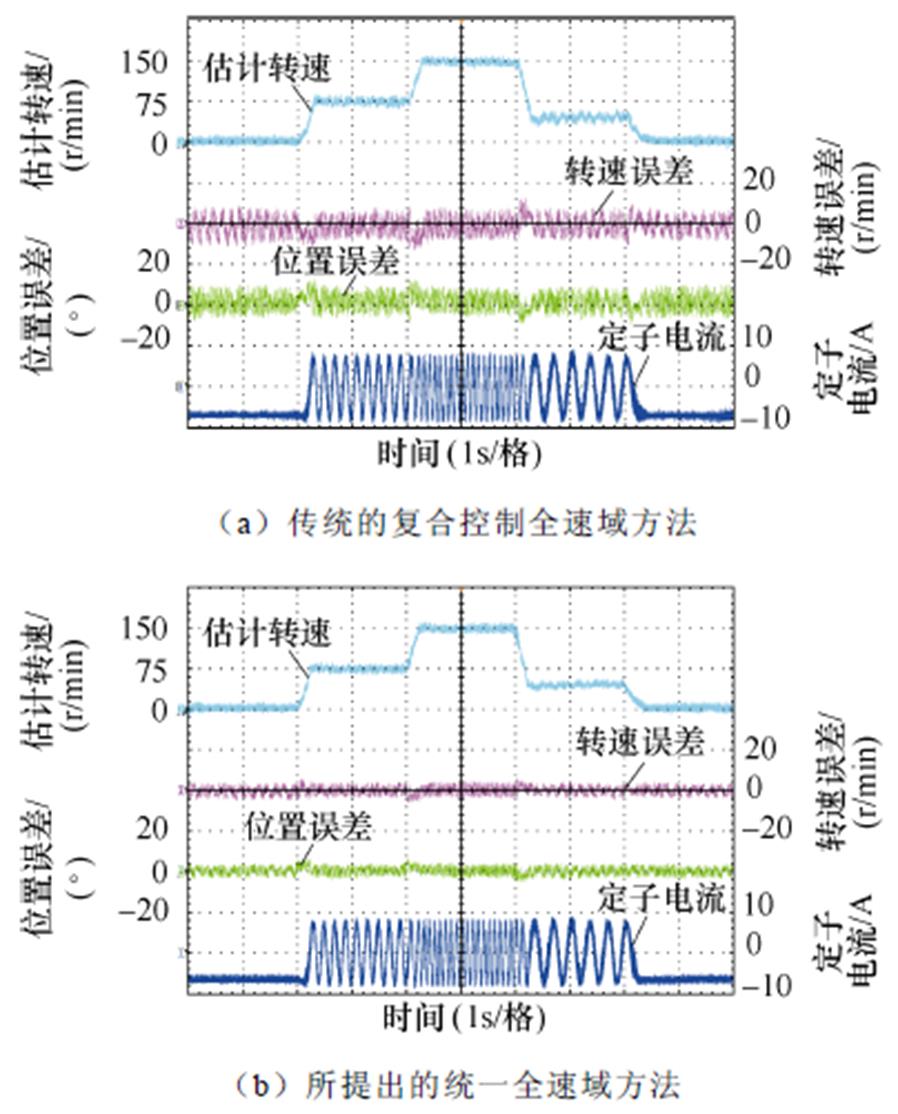
图14 额定负载多速段对比实验结果
Fig.14 Comparative experimental results with operating at different speeds with rated load
本文提出了一种基于共振ESO的IPMSM统一全速域无位置传感器控制方法,通过共振ESO观测基频反电动势和高频反电动势,然后构建统一全速域模型,所提出的方法可以通过相同的估计器实现全速域转子位置估计。在2.0 kW IPMSM实验平台上验证了所提出方法的正确性和有效性,与传统的复合控制全速方法相比,所提出的方法具有以下 优势:
1)全速域采用相同的估计器,没有过渡区,简化了控制算法并减少了调谐工作量,同时避免了频繁切换导致的转速和位置振荡。
2)消除了传统高频注入方法中由滤波器和延迟引起的估计误差。
参考文献
[1] Wu Xuan, Yu Xu, Wu Ting, et al. Complex-coefficientsynchronous frequency filter-based position estimation error reduction for sensorless IPMSM drives[J]. IEEE Transactions on Power Electronics, 2022, 37(12): 15297-15307.
[2] Zhang Yanping, Yin Zhonggang, Cao Xinping, et al. A novel SPMSM sensorless drive using discrete-time synchronous-frequency adaptive observer under low frequency ratio[J]. IEEE Transactions on Power Electronics, 2022, 37(9): 11045-11057.
[3] Bi Guangdong, Zhang Guoqiang, Wang Qiwei, et al. High-frequency injection angle self-adjustment based online position error suppression method for sensor- less PMSM drives[J]. IEEE Transactions on Power Electronics, 2023, 38(2): 1412-1417.
[4] 王琛琛, 苟立峰, 周明磊, 等. 基于改进的离散域二阶滑模观测器的内置式永磁同步电机无位置传感器控制[J]. 电工技术学报, 2023, 38(2): 387-397.
Wang Chenchen, Gou Lifeng, Zhou Minglei, et al. Sensorless control of IPMSM based on improved discrete second-order sliding mode observer[J]. Transa- ctions of China Electrotechnical Society, 2023, 38(2): 387-397.
[5] Jiang Feng, Sun Songjun, Liu Anming, et al. Robustness improvement of model-based sensorless SPMSM drivers based on an adaptive extended state observer and an enhanced quadrature PLL[J]. IEEE Transactions on Power Electronics, 2021, 36(4): 4802-4814.
[6] Gao Fengtao, Yin Zhonggang, Bai Cong, et al. A lag compensation-enhanced adaptive quasi-fading Kalman filter for sensorless control of synchronous reluctance motor[J]. IEEE Transactions on Power Electronics, 2022, 37(12): 15322-15337.
[7] Volpato Filho C J, Vieira R P. Adaptive full-order observer analysis and design for sensorless interior permanent magnet synchronous motors drives[J]. IEEE Transactions on Industrial Electronics, 2021, 68(8): 6527-6536.
[8] Zhang Yanping, Yin Zhonggang, Gao Fengtao, et al. Research on anti-DC bias and high-order harmonics of a fifth-order flux observer for IPMSM sensorless drive[J]. IEEE Transactions on Industrial Electronics, 2022, 69(4): 3393-3406.
[9] Yin Zhonggang, Zhang Yanping, Cao Xinping, et al. Estimated position error suppression using novel PLL for IPMSM sensorless drives based on full-order SMO[J]. IEEE Transactions on Power Electronics, 2022, 37(4): 4463-4474.
[10] 刘善宏, 杨淑英, 李浩源, 等. 基于旋转坐标系解调的内置式永磁同步电机旋转高频注入法位置观测[J]. 电工技术学报, 2020, 35(4): 708-716.
Liu Shanhong, Yang Shuying, Li Haoyuan, et al. Rotating high frequency signal injection based on interior permanent magnet synchronous motor rotor position estimation with the demodulation imple- mented on the synchronous reference frame[J]. Transactions of China Electrotechnical Society, 2020, 35(4): 708-716.
[11] Lee J, Kwon Y C, Sul S K. Signal-injection sensorless control with tilted current reference for heavily saturated IPMSMs[J]. IEEE Transactions on Power Electronics, 2020, 35(11): 12100-12109.
[12] Wang Gaolin, Xiao Dianxun, Zhao Nannan, et al. Low-frequency pulse voltage injection scheme-based sensorless control of IPMSM drives for audible noise reduction[J]. IEEE Transactions on Industrial Elec- tronics, 2017, 64(11): 8415-8426.
[13] Bui M X, Guan Deqi, Xiao Dan, et al. A modified sensorless control scheme for interior permanent magnet synchronous motor over zero to rated speed range using current derivative measurements[J]. IEEE Transactions on Industrial Electronics, 2019, 66(1): 102-113.
[14] Wang Gaolin, Kuang Junyao, Zhao Nannan, et al. Rotor position estimation of PMSM in low-speed region and standstill using zero-voltage vector injection[J]. IEEE Transactions on Power Electronics, 2018, 33(9): 7948-7958.
[15] 李浩源, 张兴, 杨淑英, 等. 基于高频信号注入的永磁同步电机无传感器控制技术综述[J]. 电工技术学报, 2018, 33(12): 2653-2664.
Li Haoyuan, Zhang Xing, Yang Shuying, et al. Review on sensorless control of permanent magnet synchronous motor based on high-frequency signal injection[J]. Transactions of China Electrotechnical Society, 2018, 33(12): 2653-2664.
[16] Li Chengrui, Wang Gaolin, Zhang Guoqiang, et al. Adaptive pseudorandom high-frequency square-wave voltage injection based sensorless control for SynRM drives[J]. IEEE Transactions on Power Electronics, 2021, 36(3): 3200-3210.
[17] Zhang Yanping, Yin Zhonggang, Liu Jing, et al. IPMSM sensorless control using high-frequency voltage injection method with random switching frequency for audible noise improvement[J]. IEEE Transactions on Industrial Electronics, 2020, 67(7): 6019-6030.
[18] Chen J Y, Yang S C, Tu K H. Comparative evaluation of a permanent magnet machine saliency-based drive with sine-wave and square-wave voltage injection[J]. Energies, 2018, 11(9): 2189.
[19] Chen J Y, Yang S C. Saliency-based permanent magnet machine position sensorless drive using proposed PWM injection and shunt-based current sensing for position estimation[J]. IEEE Transactions on Industrial Electronics, 2021, 68(7): 5693-5703.
[20] Zhang Guoqiang, Wang Gaolin, Wang Huiying, et al. Pseudorandom-frequency sinusoidal injection based sensorless IPMSM drives with tolerance for system delays[J]. IEEE Transactions on Power Electronics, 2019, 34(4): 3623-3632.
[21] 孙明阳, 和阳, 邱先群, 等. 随机频率三角波注入永磁同步电机无位置传感器降噪控制[J]. 电工技术学报, 2023, 38(6): 1460-1471.
Sun Mingyang, He Yang, Qiu Xianqun, et al. Random-frequency triangular wave injection based sensorless control of PMSM drives for audible noise reduction[J]. Transactions of China Electrotechnical Society, 2023, 38(6): 1460-1471.
[22] 付康壮, 刘计龙, 麦志勤, 等. 改进型IF控制结合有效磁链法的永磁同步电机全速域无位置传感器控制策略[J]. 电工技术学报, 2022, 37(22): 5704- 5716.
Fu Kangzhuang, Liu Jilong, Mai Zhiqin, et al. A full-speed domain sensorless control strategy for permanent magnet synchronous motor based on improved IF control and effective flux method[J]. Transactions of China Electrotechnical Society, 2022, 37(22): 5704-5716.
[23] 吴春, 陈科, 南余荣, 等. 考虑交叉饱和效应的变角度方波电压注入永磁同步电机无位置传感器控制[J]. 电工技术学报, 2020, 35(22): 4678-4687.
Wu Chun, Chen Ke, Nan Yurong, et al. Variable angle square-wave voltage injection for sensorless control of PMSM considering cross-saturation effect[J]. Transactions of China Electrotechnical Society, 2020, 35(22): 4678-4687.
[24] 王菁, 颜建虎, 季国东, 等. 一种基于双位置观测器的永磁同步电机低速无位置传感器控制方法[J]. 电工技术学报, 2023, 38(2): 375-386.
Wang Jing, Yan Jianhu, Ji Guodong, et al. A sensorless control method for permanent magnet synchronous machine based on dual position observers at low speed[J]. Transactions of China Electrotechnical Society, 2023, 38(2): 375-386.
[25] Wu Chun, Chen Zihao, Chen Qiang. Hybrid- modulation-based full-speed sensorless control for permanent magnet synchronous motors[J]. IEEE Transactions on Power Electronics, 2022, 37(5): 5908-5917.
[26] 阙鸿杰, 全力, 张丽, 等. 基于自适应滤波器在线解耦的磁场增强型永磁电机无位置传感器控制[J]. 电工技术学报, 2022, 37(2): 344-354.
Que Hongjie, Quan Li, Zhang Li, et al. Sensorless control of flux-intensifying permanent magnet syn- chronous motor based on adaptive Notch filter online decoupling[J]. Transactions of China Electrotechnical Society, 2022, 37(2): 344-354.
[27] Zhang Hang, Liu Weiguo, Chen Zhe, et al. An overall system delay compensation method for IPMSM sensorless drives in rail transit applications[J]. IEEE Transactions on Power Electronics, 2021, 36(2): 1316-1329.
Abstract Conventional sensorless control of permanent magnet synchronous motors in the full speed domain achieves rotor position estimation by combining the two position estimation methods. However, in wide frequency domain speed regulation, the two position estimation methods switch frequently, which can easily cause oscillations in the estimated position and speed. Moreover, the two position estimation methods require separate design and tuning, increasing the difficulty of system tuning and algorithm complexity. For this reason, this paper proposes a unified full-speed sensorless control method of interior permanent magnet synchronous motor based on resonance extended state observer.
First, the fundamental frequency back electromotive force and high-frequency back electromotive force are estimated by the resonant extended state observer. This observer adds a high-frequency disturbance estimation loop based on the traditional extended state observer. Accordingly, the high-frequency back electromotive force in the low-speed zone generated by injecting high-frequency voltage is estimated, and the fundamental frequency back electromotive force is estimated by the original disturbance estimation loop of the extended state observer. The original disturbance estimation loop of the extended state observer has the characteristics of a notch filter at the frequency of injected high-frequency voltage. In addition, it can suppress the high-frequency measurement noise, which can accurately estimate the fundamental frequency back electromotive force. The high-frequency disturbance estimation loop of the resonant extended state observer has band-pass filter characteristics with no amplitude attenuation and phase lag at the frequency of the injected high-frequency voltage, allowing it to accurately estimate the high-frequency back electromotive force.
Then, a unified model in the full-speed domain is established, and the rotor position and speed estimation are realized through the unified model. At zero speed and low speed, the signal-to-noise ratio of the fundamental frequency back electromotive force is low, so it cannot accurately estimate the fundamental frequency back electromotive force. By injecting high-frequency voltage into the d-axis, the signal-to-noise ratio of the high-frequency back electromotive force is increased. However, the high-frequency back electromotive force is modulated by the injected high-frequency signal, which cannot be directly used to estimate the rotor position. A unified full-speed domain model is constructed to achieve a high signal-to-noise ratio of rotor position information in the full-speed domain. The amplitude of the unified full-speed domain model is the sum of the square of the fundamental frequency back electromotive force amplitude and the square of the high-frequency back electromotive force amplitude. The output of the unified full-speed domain model is used as the input of the phase-locked loop, and the output of the phase-locked loop is the estimated rotor position and speed.
Finally, the correctness and effectiveness of the proposed method are verified on the 2.0 kW interiorpermanent magnet synchronous motor experimental platform. Compared with the traditional sensorless control method, the proposed method has the following advantages: (1) The full-speed domain uses the same estimator without a transition zone, simplifying the control algorithm, reducing tuning difficulty, and avoiding speed and position oscillations caused by frequent switching of the two observers. (2) Estimation errors caused by filters and delays in traditional high-frequency injection methods are eliminated.
Keywords:Permanent magnet synchronous motor, sensorless control, resonance extended state observer, unified full speed domain model
张彦平 男,1989年生,博士,讲师,研究方向为高性能变频调速系统控制策略。E-mail: zhangyanping@xaut.edu.cn
尹忠刚 男,1982年生,博士,教授,研究方向为高性能交流调速系统与电力电子变换器数字化控制。E-mail: zhgyin@xaut.edu.cn(通信作者)
中图分类号:TM351
DOI: 10.19595/j.cnki.1000-6753.tces.230597
国家自然科学基金项目(52207222, 52177194)、中国博士后科学基金面上项目(2022M722559)、陕西省自然科学基础研究计划一般项目(2022JQ-538)、电力设备电气绝缘国家重点实验室项目(EIPE22205)和陕西省自然科学基础研究计划项目(2022JM-288)资助。
收稿日期 2023-05-01
改稿日期 2023-05-18
(编辑 崔文静)