0 引言
电磁轨道发射装置( Electromagnetic Rail Launcher, EMRL)是一种在高脉冲强磁场环境下利用洛伦兹力发射弹丸的直线加速器[1-6]。绝缘体作为EMRL 的核心部件放置在两条导轨之间,起到了绝缘和支撑的双重作用。由于电磁发射过程复杂,膛内恶劣的热学环境会造成绝缘体的热损伤,导致绝缘体支撑强度下降和绝缘失效。绝缘体热损伤主要分为两个阶段:一是电枢膛内运动阶段,二是电枢出膛后炮口电弧回流阶段。研究这两个阶段绝缘体的热损伤情况对提升绝缘体支撑和绝缘性能具有重要的实际意义。
电枢膛内运动阶段产生的气动热[7]对绝缘体作用时间短,热量传递可忽略,主要考虑导轨传递给绝缘体的热量,包括焦耳热、枢-轨接触热及摩擦热。李丹等[8-9]通过二维瞬态仿真发现绝缘体最高温度和最大热应力均出现在与导轨的接触面上,导轨的热效应对绝缘体影响不大,但连发造成的热量累积会导致绝缘体强度降低和绝缘老化。姜远志等[10]通过多物理场耦合仿真,发现连发条件下每次发射后都会出现300℃的瞬态高温,G10 绝缘体在高温环境下反复工作,容易导致树脂基体的破坏和层间结合力的减弱。但这些研究都没有考虑电枢运动带来的导轨热量的时空变化对绝缘体的热影响。
炮口电弧回流阶段绝缘体主要受到高温电弧等离子体的热侵蚀。电枢出膛后,发射系统内大量的剩余能量会以电弧的形式通过炮口引弧装置释放出来[11]。由于电枢的运动速度远大于声速,导致内膛气压远低于标准大气压,炮口内外的压差是炮口电弧向膛尾回流的主要原因。J.J.Weimer 等[12]使用高速摄像机和光谱仪分析了回流电弧的组分、流动以及温度信息,发现回流温度最高可达4 000 K,为铝颗粒在1 atm(1 atm=1.013×10⁵ Pa)中的燃烧温度,回流持续了60 ms,速度约600 m/s,与文献[13-16]通过磁流体仿真获取的回流温度和速度相近,高温电弧导致了绝缘体的烧蚀。P.J.Cote 等[17-18]通过激光脉冲加热试验,复现了试验中观察到的绝缘体热损伤,包括环氧树脂热分解以及纤维尖端的软化。中国科学院电工研究所进行发射试验后,发现炮口区域绝缘体烧蚀炭化最严重[19],表面材料因高温而分解脱落,烧蚀增大了绝缘体表面粗糙度、提高了氧化物含量并带来了金属污染[20-21],导致绝缘体表面电阻率和闪络电压大幅降低[22-24]。综上可知,目前对电弧回流引起的绝缘体热损伤的研究主要集中在实验现象的描述和分析,缺乏对流-固-热耦合环境下绝缘体热侵蚀机理的研究。
因此,本文采用三维瞬态电-磁-热耦合模型分析了电枢膛内运动过程中随时间以及电枢位置变化的导轨热量对绝缘体的影响。建立考虑G10 绝缘体细观结构的流-固-热耦合模型解释了电弧回流对绝缘体的热侵蚀机理,并得到了试验验证。
1 电-磁-热耦合模型
为研究电枢膛内运动阶段导轨对绝缘体的热传导作用,建立了考虑电枢运动的三维瞬态电-磁-热耦合模型。
1.1 控制方程
基于准静态麦克斯韦方程和本构方程,通过引入矢量磁位和标量电位,得到EMRL 瞬态电磁场的控制方程统一形式为[25]

式中,μ 为相对磁导率;A 为矢量磁位;φ 为标量电位;σ 为电导率;t 为时间;v 为电枢运动速度。
EMRL 的热扩散方程可以写成[26]

式中,ρ 为材料的密度;cp 为比定压热容;T 为温度;κ 为导热系数;Q 为热源,主要由三部分组成:导轨焦耳热、枢-轨接触热及摩擦热,各项热源分别用Qe、Qc、Qf 表示,方程为
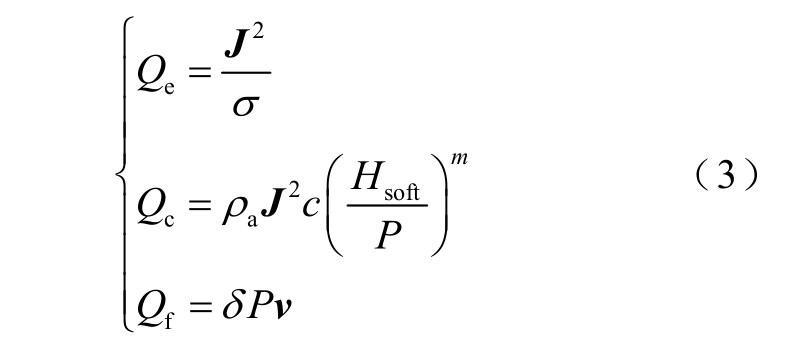
式中,J 为电流密度;ρa 为导轨和电枢的平均电阻率;Hsoft 为电枢硬度;P 为接触压强;δ 为摩擦系数;经验接触常数c=9.45×10⁻⁴,m=0.63[27]。
假设电枢为刚体,其在洛伦兹力和摩擦力的共同作用下沿着导轨x 轴运动,运动方程可以写成

式中,M 为电枢质量,M=160 g;x 为电枢的位置,起始位置为0.2 m;B 为磁感应强度;f 为摩擦阻力;V 为电枢运动区域。
1.2 建立模型
本文的研究对象为50 mm 方口径的EMRL。身管长4 m,主要由铜合金导轨、铝合金电枢和G10绝缘体组成,材料物性参数见表1。在EMRL 周围设置空气域以求解电磁场,鉴于EMRL 结构的对称特性,为提高计算效率,建立的1/4 几何模型如图1 所示。电枢运动通过改变电枢运动区域材料属性的方法实现[28-29],即在图1 所示的电枢运动区域使用铝合金属性代表电枢,其他区域定义为空气属性。在电枢和空气的交界处,电导率采用平滑逻辑函数的形式,以避免不收敛。

图1 1/4 EMRL 几何模型
Fig.1 Geometric model of the quarter EMRL
表1 材料物性参数
Tab.1 Parameters of material properties
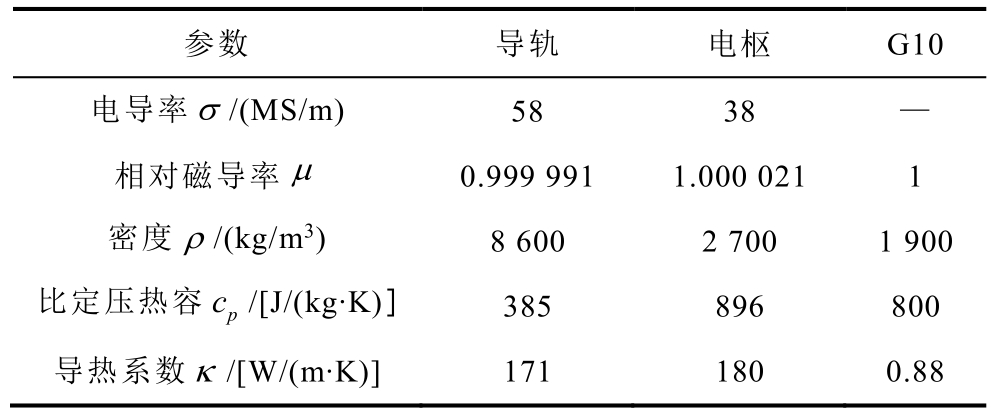
参数 导轨 电枢 G10电导率σ /(MS/m) 58 38 —相对磁导率μ 0.999 991 1.000 021 1密度ρ /(kg/m3) 8 600 2 700 1 900比定压热容 cp /[J/(kg·K)] 385 896 800导热系数κ /[W/(m·K)] 171 180 0.88
1.3 定解条件
磁场边界条件:边界S1 垂直于磁感应强度方向,n×H=0;边界S2 相切于磁感应强度方向,n×A=0;空气域边界S3 视作无穷远,n×A=0;边界S4、S5上A 的方向与电流方向一致,n×A=0。A 的初始值为0。
电场边界条件:边界S6 为导轨端面,给时变电压输入;边界S7 为电枢运动区域的对称面,设为零电位,φ=0 V;电绝缘条件适用于除S6 和S7 以外的所有边界,n·J=0。φ 的初始值为0 V。
温度场边界条件:由于电枢运动时间为ms 量级,所以边界S1、S2、S3、S4 和S5 均施加绝热边界条件,n·( κT∇ )=0。T 初始值为293.15 K。
2 流-固-热耦合模型
电枢出膛后,由于高速摩擦,转捩及炮口击穿放电,炮口区域将出现复杂的高温空气电弧等离子体流场,并在气压差的影响下向膛尾回流。为研究电弧回流持续时间内电弧对绝缘体增强体(纱线)以及基体(树脂)的热侵蚀作用,建立了考虑G10绝缘体细观结构的流-固-热耦合三维模型。
2.1 控制方程
为分析绝缘体在回流电弧作用下的流固耦合与传热问题,引入流体状态无量纲参数——雷诺数Re来判定回流电弧在膛内的流动状态,当Re>2 320时,膛内为湍流[30]。经计算,电弧在4 000 K 下的雷诺数为18 113.4,可知电弧的流动状态为湍流,故采用适用性和鲁棒性高的k-ε 模型[31]。
将空气电弧等离子体视作物性参数随温度变化的流体,该过程涉及流体的流动与传热、流体与固体界面之间的热对流以及固体自身的热传导。模型涉及质量、动量和能量三大守恒定律以及k-ε 湍流方程为
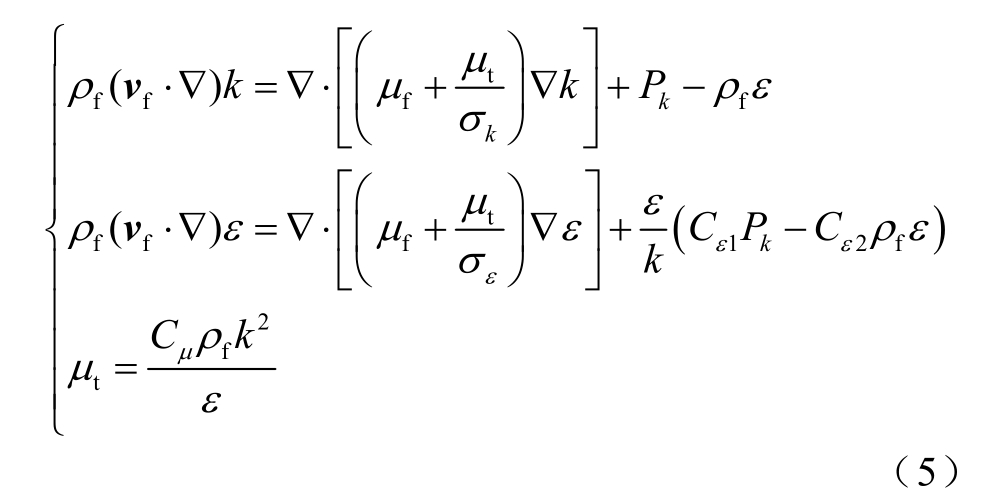
式中, fρ 为流体密度;vf 为流体微元的速度矢量;k 和ε 分别为流体的湍流动能及耗散率;μf 为流体动力粘度; tμ 为湍流粘度; kσ 和 εσ 为湍流的普朗特常数;Pk 为粘性项;Cε1 和Cε2 为模型常数;Cμ 为湍流粘度常数。
2.2 建立模型
G10 绝缘体是一种玻璃纤维层压材料,用环氧树脂粘合在一起。G10 采用玻璃纤维平面布作为增强相,铺层厚度为[(0°,90°)]120,50%的纤维分布在x 方向上,其余50%分布在y 方向上,z 方向为平面布的堆叠方向。为准确地计算电弧回流对G10 绝缘体的热侵蚀作用,构建了层合结构复合材料G10 的细观模型如图2 所示,其中纱线宽度为0.7 mm,厚度为0.125 mm,密度为10 根/cm。细观模型可以对纱线尺度进行分析,相较于宏观模型可以更好地反映纱线和树脂的温度分布,也不会像微观(纤维尺度)模型那样带来巨量的网格。纱线和树脂的物性参数以及随温度变化的空气电弧等离子体物性参数[32-34]见表2 和图3 所示。

图2 G10 细观模型
Fig.2 Meso-model of G10
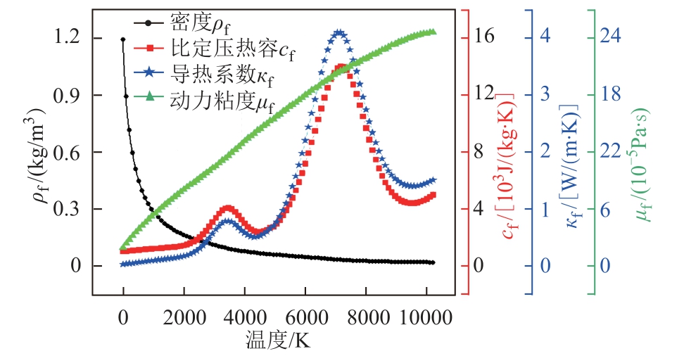
图3 电弧等离子体物性参数
Fig.3 Physical parameters of arc plasma
表2 材料物性参数
Tab.2 Parameters of material properties
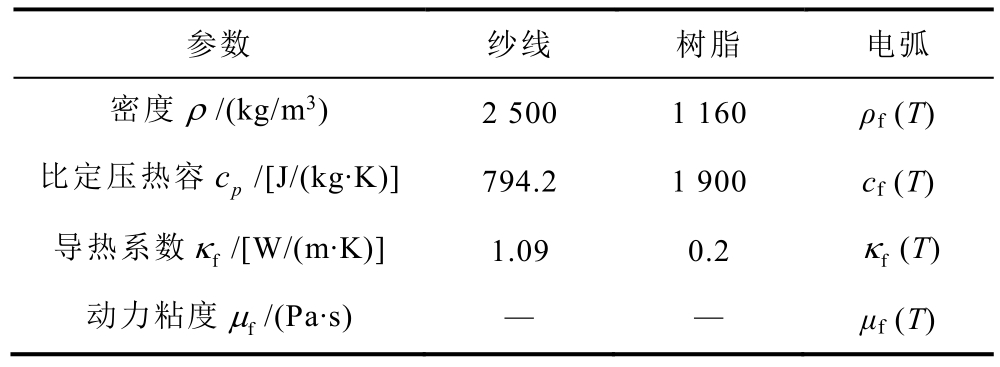
参数 纱线 树脂 电弧密度ρ /(kg/m3) 2 500 1 160 ρf (T)比定压热容 cp /[J/(kg·K)] 794.2 1 900 cf (T)导热系数 fκ /[W/(m·K)] 1.09 0.2 fκ (T)动力粘度 fμ /(Pa·s) — — μf (T)
2.3 定解条件
在COMSOL Multiphysics 有限元软件中建立几何模型并赋予物性参数后,使用了“湍流,k-ε”和“固体和流体传热”两个物理场模块,并通过多物理场中的“非等温流动”模块将两个物理场耦合起来。
根据文献[12-16],假设炮口回流电弧的温度为4 000 K,流速为600 m/s,电枢出膛时内膛气压接近于真空状态。回流持续时间与发射能级相关,本文选取试验工况下实测的10 ms,得到定解条件如下:
内膛区域为流体,流体边界条件:在“湍流,k-ε”模块中选择边界S8 为流体入口,对其赋予“充分发展的流动”边界条件,平均流速为600 m/s。边界S9 为流体出口,设置出口压力为0 Pa。边界S10、S11 设置为对称面,其余面设置为壁面。内膛流体区域的初始速度及初始压力都为0。
G10 绝缘体区域为固体,固体和流体传热边界条件:边界S8 为高温流体入口,温度为4 000 K;边界S9 为出口;边界S10、S11 设置为对称面;由于计算时间仅为10 ms,所以其他边界设置为绝热条件。整个区域的初始温度都为293.15 K。
3 结果与讨论
3.1 电枢膛内运动阶段
仿真计算得到的驱动电流波形如图4 所示。驱动电流为脉冲大电流,上升沿约为1 ms,峰值约为0.442 MA,电枢出膛时刻为5.7 ms。
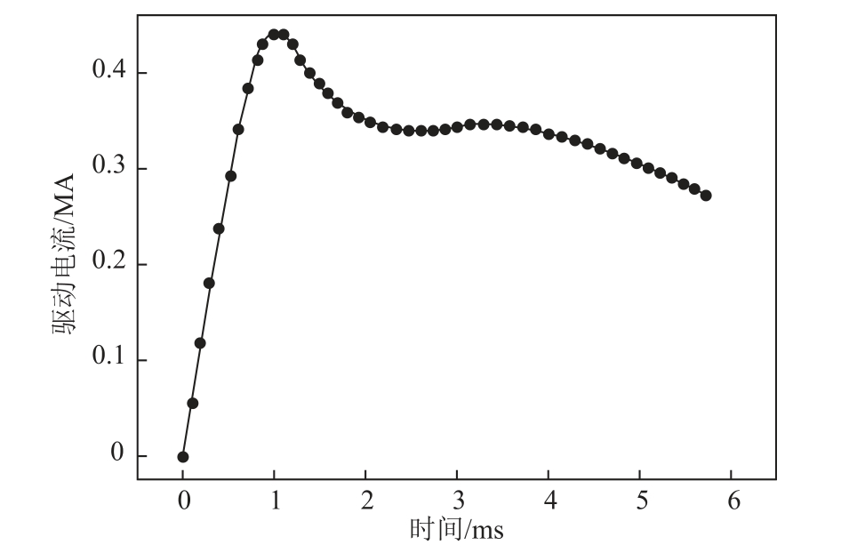
图4 驱动电流曲线
Fig.4 Driving current curve
在电流趋肤效应、速度趋肤效应以及邻近效应的影响下,电流密度会趋于导轨内表面分布,图5为电流上升沿时刻(0.7 ms)导轨的电流密度分布。可以看出导轨内表面的电流密度明显高于导轨内部,且更趋向于集中在导轨两侧边缘,即与绝缘体的接触面。再加上枢-轨接触电阻以及滑动摩擦的影响,集中于导轨内表面的热量会通过与绝缘体的接触面传递到绝缘体上。
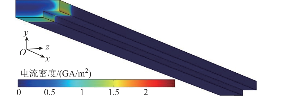
图5 0.7 ms 时刻导轨的电流密度分布
Fig.5 Current density distribution of the rail at 0.7 ms
1.2 ms(最高温度时刻)和5.7 ms(电枢出膛时刻)导轨和绝缘体的温度分布分别如图6 和图7 所示。由图6 和图7 可知随着电枢的运动,导轨和绝缘体的高温区域不断向口部方向延伸,但尾部至口部的温升呈逐渐减小的趋势,最高温度始终出现在电枢起始位置附近。原因如下:首先,电枢在起始位置附近速度较低,加热时间较长;其次,该段时间为电流急剧上升段,涡流效应更加明显,对应的焦耳热效应更为显著;最后,该阶段电枢与导轨的接触状态较差,接触电阻很大。

图6 1.2 ms 时刻导轨和绝缘体的温度分布
Fig.6 Temperature distributions of the rail and insulator at 1.2 ms

图7 5.7 ms 时刻导轨和绝缘体的温度分布
Fig.7 Temperature distributions of the rail and insulator at 5.7 ms
由于G10 绝缘体的绝缘等级为B 级,这意味着G10 绝缘体最高允许工作温度为403 K[10]。单次发射过程中,在1.2 ms 时刻与导轨接触的绝缘体内表面出现最高温度401 K,接近最高允许工作温度,如图6 中放大的A 区所示。考虑连续发射过程中绝缘体温度的累积,需对导轨进行冷却系统设计[35],尤其是导轨尾部、电枢起始位置附近以及导轨内表面的有效冷却,以避免绝缘材料老化而影响支撑性能。
3.2 炮口电弧回流阶段
电枢出膛后,炮口区域的高温电弧等离子体会在短时间内流回内膛,炮口电弧回流示意图如图8所示。图9 和图10 分别为电弧持续回流10 ms 后G10 绝缘体纱线和树脂的温度分布。其中,玻璃纤维纱线的热分解温度约1 000 K,环氧树脂的热分解温度约450 K。
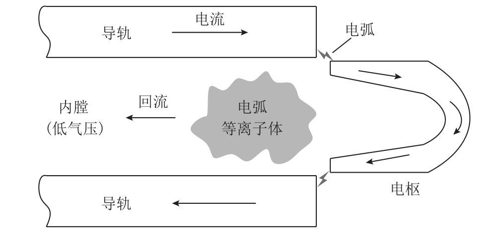
图8 炮口电弧回流示意图
Fig.8 Schematic of muzzle arc blowback
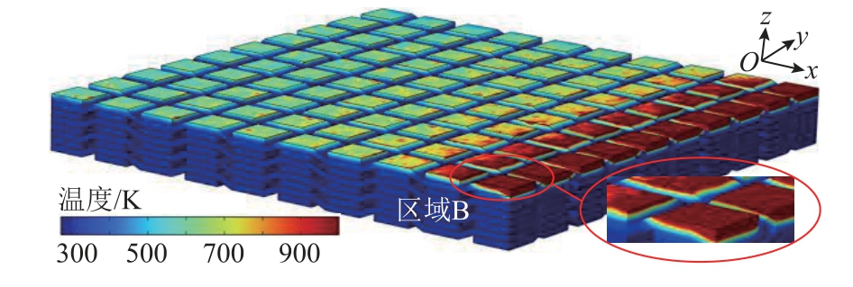
图9 纱线的温度分布
Fig.9 Temperature distribution of yarn

图10 树脂的温度分布
Fig.10 Temperature distribution of resin
从图9 可以看出,得益于纤维纱线较高的分解温度,仅距离绝缘体口部1.3 mm 范围内的纱线达到热分解点。热侵蚀深度从口部0 mm 处的0.125 mm逐渐降至口部1.3 mm 处的0 mm,如图中放大的B区所示。可知回流电弧仅会对绝缘体口部1.3 mm 范围内的纱线造成“倒角”状热损伤,即回流电弧对绝缘体纱线的影响很小。
从图10 可以看出,由于环氧树脂分解温度较低,距离绝缘体口部10 mm 范围内的树脂均达到热分解点。热侵蚀深度沿尾部方向略呈下降趋势,口部0 mm 处最深为0.125 mm,如图中放大的C 区所示,平均侵蚀深度约0.07 mm。基于计算效率的考虑,本文仅建立了10 mm 长模型,但通过对仿真结果的合理推测,可知回流电弧对绝缘体内表面电弧流经区域的树脂均会造成一定程度的热分解,树脂的大范围热分解是电弧回流带来的主要热损伤。
3.3 试验结果及分析
在实际的发射过程中,质量为160 g 的电枢在电磁力的作用下向炮口运动。基于EMRL 动态特性测试平台[36-37],对电枢通过B 点探头位置的时间值进行插值拟合,获得发射过程中电枢的实时速度及位置。电枢实测和仿真的运动速度及位移曲线如图11 所示,两者一致性较好。

图11 电枢运动曲线
Fig.11 Motion curve of the armature
对试验后的EMRL 样机进行拆解,观察膛内G10 绝缘体的热损伤情况。图12 为试验后距离炮口500 mm 范围内的绝缘体的典型宏观状态,其中放大区域为绝缘体口部局部位置。区域D 出现了“倒角”状损伤,判断为该处的纤维纱线和树脂均被热分解所致。膛内电弧流经区域的绝缘体内表面纤维纱线之间出现了大量的孔洞,并附着炭化分解产物以及银色金属污染物,原因是填充在纱线之间的树脂被大范围热分解炭化,同时回流电弧中的熔融铝颗粒会附着在绝缘体表面。可知,回流电弧仅会对绝缘体口部很小范围纱线造成“倒角”状热损伤,树脂的热分解损伤占主导地位,试验现象与仿真得到的热侵蚀规律一致。

图12 试验后绝缘体的典型宏观状态
Fig.12 Typical macroscopic state of the insulator after test
炮口电弧回流带来的绝缘体内表面树脂热分解炭化和金属污染,会导致绝缘体表面电阻率和闪络电压大幅降低。抑制炮口电弧回流以及提高绝缘材料的抗热侵蚀能力有助于避免绝缘失效。采用炮口消弧装置是一种抑制炮口电弧回流的有效手段;提高纤维纱线密度以减小单位体积内易被热分解的树脂含量,或者选用耐热性能优异的改性树脂都可以很好地提高绝缘材料的抗热侵蚀能力。
4 结论
本文建立了三维瞬态电-磁-热耦合模型以及考虑G10 绝缘体细观结构的流-固-热耦合模型来分析绝缘体的热损伤情况,得到以下结论:
1)电枢膛内运动阶段,绝缘体的高温区域随电枢运动而向口部延伸,但尾部至口部的温升逐渐降低,最高温度始终出现在电枢起始位置附近,接近绝缘体最高允许工作温度。
2)炮口电弧回流阶段,回流电弧对绝缘体纱线的影响很小,仅口部1.3 mm 范围内的纱线形成“倒角”状热损伤。但对绝缘体内表面电弧流经区域的树脂造成了大范围热分解,树脂的热分解损伤占主导地位。试验现象与仿真得到的热侵蚀规律一致。
3)连续发射会带来绝缘体温度的累积,对导轨进行冷却系统设计以避免绝缘材料老化而影响支撑性能。电弧回流会带来绝缘体内表面炭化和金属污染,采用炮口消弧装置以及提高树脂的抗热侵蚀能力有助于避免绝缘失效。
[1] 鲁军勇, 马伟明.电磁轨道发射理论与技术[M].北京: 科学出版社, 2020.
[2] 李白, 鲁军勇, 谭赛, 等.高速滑动电接触电枢表面动态磨损过程研究[J].电工技术学报, 2023,38(1): 131-139.Li Bai, Lu Junyong, Tan Sai, et al.Research on dynamic wear process of armature surface in highspeed sliding electric contact[J].Transactions of China Electrotechnical Society, 2023, 38(1): 131-139.
[3] 张嘉炜, 鲁军勇, 谭赛, 等.考虑初始接触压力的滑动电接触界面磁扩散模型[J].电工技术学报,2022, 37(2): 488-495.Zhang Jiawei, Lu Junyong, Tan Sai, et al.A magnetic diffusion model of electromagnetic launcher considering initial contact pressure[J].Transactions of China Electrotechnical Society, 2022, 37(2): 488-495.
[4] 李湘平, 鲁军勇, 张晓, 等.基于NSGA-II 的过载磁场发生器优化设计[J].电工技术学报, 2021,36(21): 4399-4407.Li Xiangping, Lu Junyong, Zhang Xiao, et al.Optimization of generator of high overload and strong magnetic field based on NSGA-II[J].Transactions of China Electrotechnical Society, 2021, 36(21): 4399-4407.
[5] 李湘平, 鲁军勇, 张晓, 等.电磁发射弹丸膛口磁场分布特性分析[J].电工技术学报, 2021, 36(3):525-531.Li Xiangping, Lu Junyong, Zhang Xiao, et al.Analysis of distribution characteristics of electromagnetic launcher projectile muzzle magnetic field[J].Transactions of China Electrotechnical Society, 2021,36(3): 525-531.
[6] 张晓, 鲁军勇, 李湘平, 等.电磁感应线圈发射子弹系统优化设计[J].电工技术学报, 2021, 36(22):4658-4665.Zhang Xiao, Lu Junyong, Li Xiangping, et al.System optimization of electromagnetic induction coil launch bullet[J].Transactions of China Electrotechnical Society, 2021, 36(22): 4658-4665.
[7] 冯军红, 鲁军勇, 李开, 等.电磁发射弹丸膛内流场数值分析[J].海军工程大学学报, 2021, 33(3): 43-48.Feng Junhong, Lu Junyong, Li Kai, et al.Numerical analysis of in-bore flow field of electromagnetic launcher projectile[J].Journal of Naval University of Engineering, 2021, 33(3): 43-48.
[8] 李丹, 徐蓉, 袁伟群, 等.电磁发射装置绝缘支撑结构多场特性研究[J].电工电能新技术, 2016,35(8): 36-39.Li Dan, Xu Rong, Yuan Weiqun, et al.Study on multiphysics characteristics of insulators in electromagnetic launcher system[J].Advanced Technology of Electrical Engineering and Energy,2016, 35(8): 36-39.
[9] Li D, Xu R, Yan P, et al.Thermal analysis of insulators in electromagnetic launcher system[C]//2015 IEEE 11th International Conference on the Properties and Applications of Dielectric Materials(ICPADM), Sydney, NSW, Australia, 2015: 780-783.
[10] Jiang Yuanzhi, Lu Junyong, Wu Hai, et al.Analysis of GFRP insulator characteristics under multiphysical fields in electromagnetic rail launchers[J].Composite Structures, 2019, 221: 110900.
[11] Cai Xiyuan, Tan Sai, Lu Junyong, et al.Simulation and analysis of muzzle arc of electromagnetic rail launch[J].IEEE Transactions on Plasma Science,2021, 49(9): 3016-3021.
[12] Weimer J J, Singer I L.Temperatures from spectroscopic studies of hot gas and flame fronts in a railgun[J].IEEE Transactions on Plasma Science,2011, 39(1): 174-179.
[13] Gao Yuan, Ni Yanjie, Wang Zhaoxin, et al.Modeling and simulation of muzzle flow field of railgun with metal vapor and arc[J].Defence Technology, 2020,16(4): 802-810.
[14] Gao Yuan, Xiao Hongcheng, Ni Yanjie, et al.Simulation and analysis of the railgun muzzle flow field considering the arc plasma[J].IEEE Transactions on Plasma Science, 2019, 47(5): 2242-2249.
[15] Gao Yuan, Ni Yanjie, Li Baoming.Numerical analysis of railgun muzzle flow field with multi-component plasma[J].Journal of Physics: Conference Series,2020, 1507(7): 072003.
[16] 高源, 王昭昕, 肖宏成, 等.回流效应下电磁轨道炮膛口电弧运动的数值分析[J].力学与实践, 2020,42(03): 331-336.Gao Yuan, Wang Zhaoxin, Xiao Hongcheng, et al.Numerical analysis of arc motion in railgun muzzle under the effect of backflow[J].Mechanics in Engineering, 2020, 42(03): 331-336.
[17] Cote P J, Johnson M A, Truszkowska K, et al.Analysis of HEMCL railgun insulator damage[R].Watervliet,NY, USA: ARAEW-TR-06012, 2006.
[18] Gee R M, Persad C.Multishot performance of an insulator in a laboratory electromagnetic launcher[J].IEEE Transactions on Magnetics, 2001, 37(1): 257-262.
[19] Xu Rong, Li Dan, Zhao Weikang, et al.Research on insulation problems under multishot experiments in electromagnetic rail launcher[J].IEEE Transactions on Plasma Science, 2017, 45(7): 1353-1360.
[20] 赵伟康, 徐蓉, 袁伟群, 等.电磁轨道发射装置内膛绝缘性能研究[J].科技导报, 2017, 35(15): 34-39.Zhao Weikang, Xu Rong, Yuan Weiqun, et al.Investigation on insulation support performance in electromagnetic launcher[J].Science & Technology Review, 2017, 35(15): 34-39.
[21] Zhao Weikang, Che Yingdong, Kong Youjun, et al.Muzzle blowback and its effects on degradation of bore insulator[J].IEEE Transactions on Plasma Science, 2020, 48(6): 2254-2260.
[22] Zhao Weikang, Tian Wen, Yuan Weiqun, et al.Armature ejecta and its effects on insulator degradation in solid-armature launchers[J].IEEE Transactions on Plasma Science, 2022, 50(2): 489-495.
[23] 李丹.大电流直线驱动装置中的绝缘问题研究[D].北京: 中国科学院大学, 2016.
[24] 夏天威, 徐蓉, 袁伟群, 等.电磁轨道发射装置绝缘支撑性能研究[J].电工电能新技术, 2018, 37(3):49-54.Xia Tianwei, Xu Rong, Yuan Weiqun, et al.Study on deterioration of insulation support performance in repeated emission[J].Advanced Technology of Electrical Engineering and Energy, 2018, 37(3): 49-54.
[25] Zhang Yongsheng, Lu Junyong, Tan Sai, et al.Dynamic response of interior ballistic process and rail stress in electromagnetic rail launcher[J].IEEE Transactions on Plasma Science, 2019, 47(5): 2172-2178.
[26] Zhang Yongsheng, Lu Junyong, Tan Sai, et al.Heat generation and thermal management of a rapid-fire electromagnetic rail launcher[J].IEEE Transactions on Plasma Science, 2019, 47(5): 2143-2150.
[27] Hsieh K T, Satapathy S, Hsieh M T.Effects of pressure-dependent contact resistivity on contact interfacial conditions[J].IEEE Transactions on Magnetics, 2009, 45(1): 313-318.
[28] Lin Lingshu, Yuan Weiqun, Zhao Ying, et al.Thermal analysis on electromagnetic launcher under transient conditions[J].IEEE Transactions on Plasma Science,2017, 45(7): 1476-1481.
[29] 郑杜成, 徐蓉, 成文凭, 等.高速滑动电接触导轨温度场与热应力的仿真分析[J].电工电能新技术,2019, 38(11): 33-38.Zheng Ducheng, Xu Rong, Cheng Wenping, et al.Simulation analysis of temperature field and thermal stress of rail in high speed sliding electrical contact system[J].Advanced Technology of Electrical Engineering and Energy, 2019, 38(11): 33-38.
[30] 党园, 姜东飞, 谷倩倩, 等.基于COMSOL 热流固耦合的金属氧化物避雷器密封结构优化[J].高电压技术, 2020, 46(3): 852-859.Dang Yuan, Jiang Dongfei, Gu Qianqian, et al.Optimization of sealing structure of metal oxide arrester based on COMSOL thermal-fluid-solid coupling[J].High Voltage Engineering, 2020, 46(3):852-859.
[31] Singhal A K, Athavale M M, Li H, et al.Mathematical basis and validation of the full cavitation model[J].Journal of Fluids Engineering, 2002, 124(3): 617-624.
[32] Murphy A B.Transport coefficients of air, argon-air,nitrogen-air, and oxygen-air plasmas[J].Plasma chemistry and plasma processing, 1995, 15(2): 279-307.
[33] Murphy A B.The effects of metal vapour in arc welding[J].Journal of Physics D: Applied Physics,2010, 43(43): 434001.
[34] Murphy A B.Transport coefficients of plasmas in mixtures of nitrogen and hydrogen[J].Chemical Physics, 2012, 398: 64-72.
[35] 林灵淑, 赵莹, 袁伟群, 等.电磁轨道发射的瞬态温度效应[J].高电压技术, 2016, 42(9): 2864-2869.Lin Lingshu, Zhao Ying, Yuan Weiqun, et al.Thermal effect analysis of railgun tests under transient conditions[J].High Voltage Engineering, 2016, 42(9):2864-2869.
[36] Zeng Delin, Lu Junyong, Cheng Long, et al.A novel measurement method of solid armature’s in-bore motion state using B-dot probes for rail Gun[J].IEEE Transactions on Plasma Science, 2019, 47(5): 2472-2478.
[37] Li Xiangping, Lu Junyong, Feng Junhong, et al.Modeling for the calculation of interior ballistic velocity of electromagnetic rail launch projectile[J].IEEE Transactions on Plasma Science, 2019, 47(1):807-813.