 (1)
(1)
摘要 在感应电机有限集预测转矩控制中,权重因子的配置是多控制目标协同优化的关键参数。由于缺乏理论指导,通常采用试凑法,因而难以实现电驱系统的最优控制。针对此问题,该文提出基于新型解析权重配置的感应电机预测转矩控制。首先,分析了不同转速转矩工况下,权重因子对电磁转矩脉动、定子磁链幅值脉动和电流谐波含量的影响机理。然后,依据感应电机电磁关系的内在联系,解析地推导了权重因子配置的数学表达式,可实现不同工况下感应电机的多目标最优控制。鉴于权重因子解析表达式依赖于电机参数,该文融合了在线参数辨识技术,可实现权重因子及预测模型的计算精度。实验结果验证了所提算法的有效性。
关键词:模型预测控制 感应电机 预测转矩控制 权重因子 代价函数
在经典的矢量控制中,电压源逆变器相当于一个基于空间矢量脉宽调制(Space Vector Pulse Width Modulation, SVPWM)的连续电压放大器,电气驱动系统的设计采用经典线性控制[1-4]。但电压源逆变器本质上是一种开关组合方式的能量转换装置,具有分立式的特点。有限集模型预测控制(Finite Control Set-Model Predictive Control, FCS-MPC)将电机和逆变器视为一个整体,基于穷举法选择最优电压矢量。此外,FCS-MPC的代价函数易于处理非线性多变量[5-8]。与经典矢量控制和直接转矩控制(Direct Torque Control, DTC)相比,FCS-MPC以其诸多优势成为学术界的研究热点[9-11]。根据控制变量的不同,FCS-MPC可分为有限集模型预测电流控制(Finite Control Set-Model Predictive Current Control, FCS-MPCC)和有限集模型预测转矩控制(Finite Control Set-Model Predictive Torque Control, FCS-MPTC)[12]。FCS-MPCC以定子电流为控制目标,而FCS-MPTC以电磁转矩和定子磁链幅值为控制目标[13-14]。与FCS-MPCC相比,FCS-MPTC具有电磁转矩动态响应快、弱磁控制容易等优点[15]。然而,FCS-MPTC代价函数的权重因子分配一直是学术界的研究难点。在FCS-MPTC中,通常根据电磁转矩跟踪误差和定子磁链幅值跟踪误差来设计代价函数。电磁转矩和定子磁链具有不同的量纲,需要利用权重因子来平衡二者。而且,由于FCS-MPC的本质是对离散电压矢量的穷举法,因此没有成熟的控制理论来分析其设计方法。由此可知,权重因子的设定也缺乏理论依据。评级法和试凑法是两种经典的权重因子设计策略。评级法将定子磁链项的权重因子设置为额定电磁转矩与额定定子磁链幅值的比值。该方法可以在感应电机的额定工况下实现电磁转矩和定子磁链的协调控制,但在其他工况下控制性能较差。试凑法通过反复在线调试得到权重因子配置,不仅过程繁琐,而且难以获得最优控制,尤其是当控制目标和权重因子较多时[16-17]。
为解决这个问题,学者们进行了广泛的研究和探索。在文献[18]中,对模型预测转矩控制(Model Predicts Torque Control, MPTC)和模型预测磁链控制(Model Predictive Flux Control, MPFC)进行了比较,其中MPFC以定子磁链矢量为控制目标,避免了权重因子的循环工作。同时,与MPTC相比,MPFC具有可观的控制性能。但是,定子磁链矢量参考值的计算依赖电机参数,降低了控制系统的鲁棒性。在文献[19]中,针对中点钳位型三电平逆变器馈电感应电机(Induction Motors, IM)驱动器详细讨论了MPFC,提出了弱磁控制策略并进行了实验研究。此外,也有学者将多目标优化理论引入FCS-MPTC的代价函数设计中。在文献[20]中,提出了由两层顺序结构设计的容差顺序代价函数来选择满足转矩容差的电压矢量,然后通过磁链容差获得最优电压矢量。这样就避免了繁琐的权重因子设置,直接通过容差值来选择电压矢量。近年来,一些学者将智能优化方法引入FCS-MPC的权重因子设置中。在文献[21]中,对FCS-MPTC的代价函数进行了模糊决策的多目标优化。在文献[22]中,提出了一种基于神经网络的权重因子设计方法,通过扫描IM的操作模式来建立适应度函数。然后通过适应度函数来设置代价函数的权重因子得到最优电压矢量。该方法实现了权重因子的优化设计,但过程较复杂。在文献[23]中,粒子群优化(Particle Swarm Optimization, PSO)首次被引入FCS-MPTC代价函数的权重因子设计中。首先通过理论推导建立PSO目标函数,然后利用PSO得到最优电压矢量。众所周知,收敛时间是影响FCS-MPTC性能的一个重要因素。因此,基于智能优化权重因子的方法面临的一个问题是该方法增加了整个系统的复杂性和微处理器的计算负担。
在本文中,首先提出了一种带解析权重因子的模型预测转矩控制(Analytical Weighting Factor- Model Predictive Torque Control, AWF-MPTC),以实现权重因子的最优配置。同时权重因子会随着负载转矩的变化而自行调整。首先,介绍了用于感应电机驱动器的MPCC、MPTC和MPFC的设计原则。其次,详细介绍了解析权重因子的推导过程并研究了其参数敏感度。为了进一步提高FCS-MPTC的鲁棒性,提出了一种结合在线参数辨识的解析权重因子计算方法。最后,通过实验验证了所提出的AWF- MPTC算法。
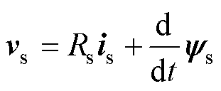
三相异步感应电机的空间矢量连续数学模型表示[24-25]为
(1)
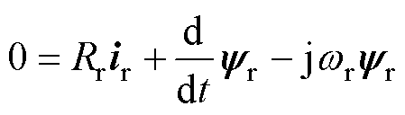 (2)
(2)
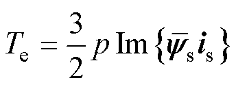 (3)
(3)
式中, 、
、 、
、 和
和 分别为定子电压矢量、定子电流矢量、定子磁链矢量和转子磁链矢量;
 、
、 和
和 分别为定子电阻、转子电阻和转子速度;
 为IM的极对数;
 为电磁转矩。
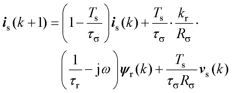
基于上述连续数学方程式(1)~式(3)和一阶欧拉向前离散方程,对于FCS-MPC,感应电机的离散预测模型[26-28]表示为
 (4)
(4)
 (5)
(5)
 (6)
(6)
其中

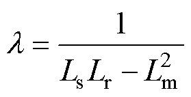
式中, 为控制周期;w 为转子电角速度;Ls、Lr和Lm分别为定子电感、转子电感和励磁电感。
根据FCS-MPC的运算原理,在采样时间 内通过电流传感器可以得到
 。
。 和
和 通过磁链观测器估计。
 为在采样时间内施加的电压矢量,是两电平电压源逆变器产生的7个电压矢量之一。当
 时,根据预测模型式(4)~式(6)可以产生7组不同的定子电流矢量、定子磁链矢量和电磁转矩。可以选择使代价函数最小化的电压矢量作为最优电压矢量,并在
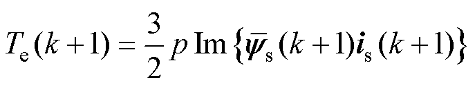
 次时应用。感应电机的FCS-MPC具体框图如图1所示。根据代价函数的设计原则,FCS-MPC可分为有限集模型预测电流控制(FCS-MPCC)、有限集模型预测转矩控制(FCS-MPTC)和有限集模型预测磁链控制(Finite Control Set-Model Predictive Flux Control, FCS-MPFC)。
在感应电机驱动的FCS-MPCC中,以定子电流跟踪误差最小作为最优电压矢量的选择标准。具体的代价函数设计为
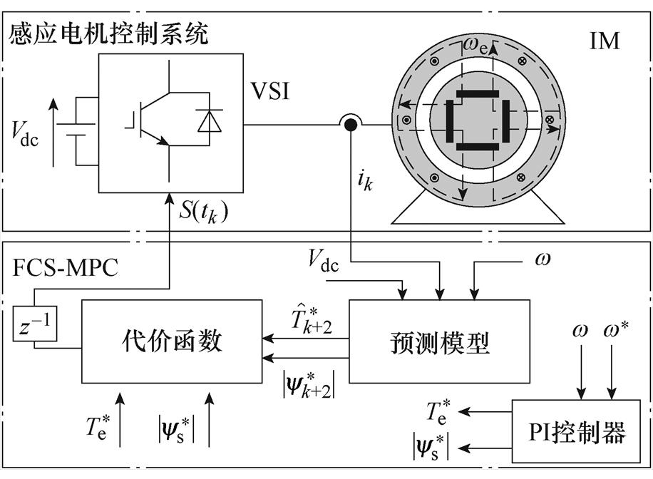
图1 感应电机FCS-MPC具体框图
Fig.1 The specific block diagram of FCS-MPC for IM
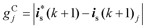 (7)
(7)
式中, 为定子电流参考值,从速度环中获取。FCS-MPCC以定子电流为控制目标,通过定子电流间接控制电磁转矩。
在感应电机驱动的FCS-MPTC中,电磁转矩和定子磁链为控制目标,其代价函数的设计为
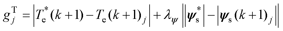 (8)
(8)
式中, 为电磁转矩参考值,从调速器的输出中获得;
 为定子磁链参考值,通常设为额定值;且由于电磁转矩和定子磁链量纲不同,因此需要引入权重因子
 来协调二者的权重,的值既决定了电磁转矩和定子磁链的重要性,也决定了最优电压矢量的选择原则。
权重因子的设置通常采用评级法和试凑法,没有严格的理论依据。本文首先研究了不同权重因子对定子电流总谐波畸变率(Total Harmonic Dis- tortion, THD)、电磁转矩均方差(Root Mean Square, RMS)和定子磁链RMS的影响机理。定子磁链RMS和电磁转矩RMS的数学表达式分别为
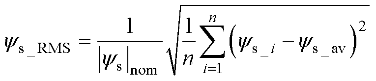 (9)
(9)
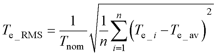 (10)
(10)
式中, 为稳态时采样点i的定子磁链矢量;
 为平均值;
为平均值; 为采样点数,为了提高计算精度,设n=
 ;
; 为定子磁链额定值;
 为电磁转矩额定值;
 为稳态时电磁转矩矢量的采样点;
 为平均值。
为平均值。
通过仿真研究,不同运行状态下不同权重因子的定子电流THD、定子磁链RMS和电磁转矩RMS如图2所示,需要注意的是,定子电流THD用小数而不是百分比表示。从图2a~图2f可以看出,定子磁链RMS随着权重因子的增加而减小,而电磁转矩RMS则正好相反,特别需要指出的是,定子电流THD先减小后增大。由上述结果可以看出,当 时,感应电机的FCS-MPTC具有更好的稳态性能。当
 或
或 时,由于定子电流THD较大,感应电机的FCS-MPTC不能正常运行。图2a表明,在额定转速和额定转矩下,感应电机的FCS-MPTC具有良好的稳态性能。而图2f表明,低速轻载状态下,FCS-MPTC稳态性能最差。

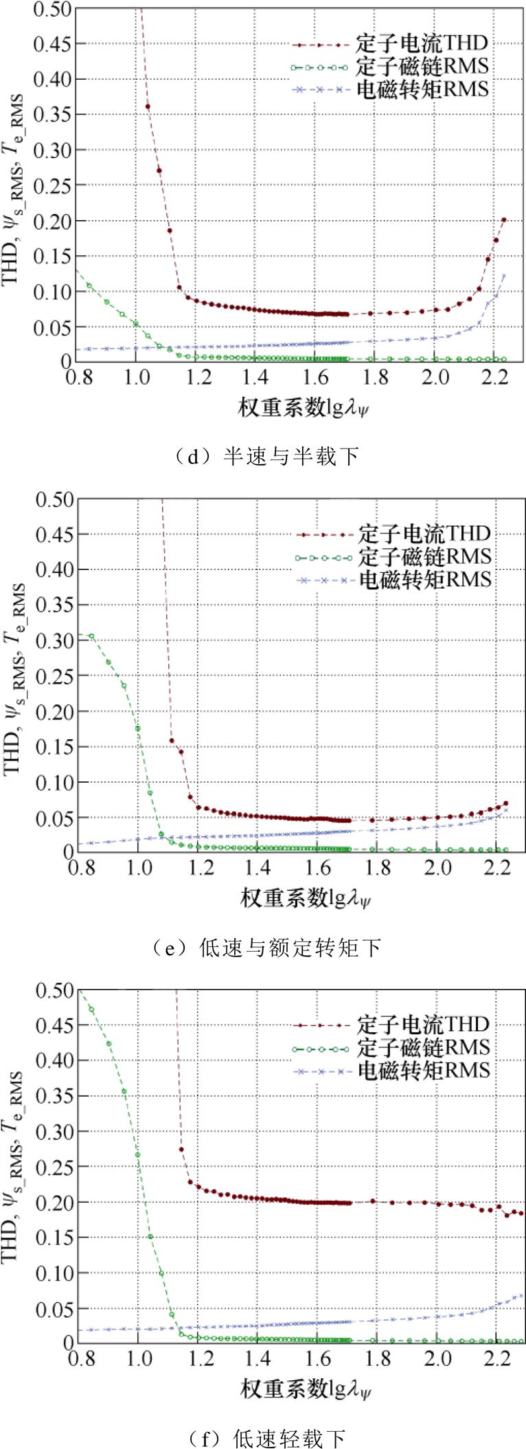
图2 不同工况不同权重因子下感应电机的定子电流THD、定子磁链RMS及电磁转矩RMS
Fig.2 Stator current THD, stator flux RMS and torque RMS of IM for different weighting factors with different operation states
在感应电机的FCS-MPTC中,评级法是一种经典的权重因子设置法,其中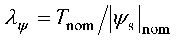 为常数。不同工况下标称权重因子的定子电流THD、定子磁链RMS和电磁转矩RMS如图3所示。可以看出,IM的FCS-MPTC在不同的工况下呈现出不同的稳态性能。在图3a、图3b中,当感应电机FCS- MPTC低速运行时,定子磁链RMS和电磁转矩RMS的性能变差。对于低速轻载下的感应电机FCS- MPTC,定子电流THD呈现大谐波。
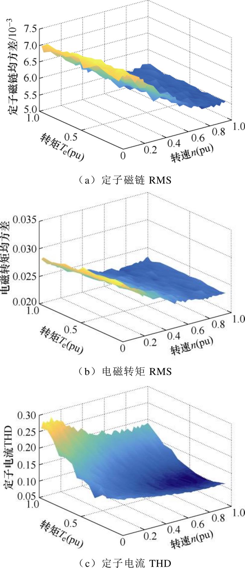
图3 不同工况标称权重因子下感应电机的定子电流THD、定子磁链RMS及电磁转矩RMS
Fig.3 Stator current THD, stator flux RMS and torque RMS of IM for nominal weighting factor with different operation states
为了保持IM的FCS-MPTC中电磁转矩直接调节的优势,并克服其权重因子 调试的繁琐工作,有学者提出了有限集模型预测磁链控制(Finite Control Set-Model Predictive Flux Control, FCS- MPFC)。IM的FCS-MPFC的代价函数设计为
 (11)
(11)
其中
 (12)
(12)
 (13)
(13)
 (14)
(14)
式中, 为FCS-MPFC的代价函数;
 为定子磁链预测值;
 为定子磁链参考值;
 为定子磁链幅值参考值,其设置方法与FCS-MPTC相同;
 为定子磁链的角度;
 为转子磁链
为转子磁链 的角度;
的角度; 为定子磁链和转子磁链之间的角度差。
根据感应电机的电磁关系,电磁转矩公式可改写为
 (15)
(15)
 (16)
(16)
其中
式中, 为电磁转矩参考值,是IM驱动器速度环的输出。因此,可以通过式(16)获得角度差。
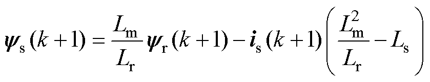
根据感应电机的数学模型式(1)~式(3),可以推导出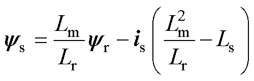 。所以,感应电机定、转子磁链参考值、
 和定子电流可以表示为
 (17)
(17)
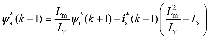
类似地,预测值 、和
、和 可以表示为
可以表示为
 (18)
(18)
通过式(17)和式(18),FCS-MPFC的代价函数式(11)可以简化为
 (19)
(19)
重写FCS-MPFC的代价函数和FCS-MPCC的代价函数 分别为
分别为
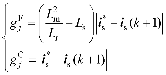 (20)
(20)
可以看出,与FCS-MPCC的代价函数相比,FCS-MPFC的代价函数只多了一个系数 。代价函数的作用是选择最优电压矢量。因此,系数不影响电压矢量的选择标准,可以认为FCS-MPCC和FCS-MPFC的代价函数是等价的。
在本文中,一种新型代价函数被设计为
 (21)
(21)
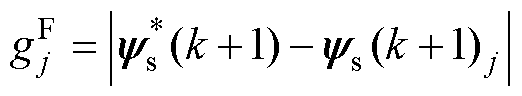
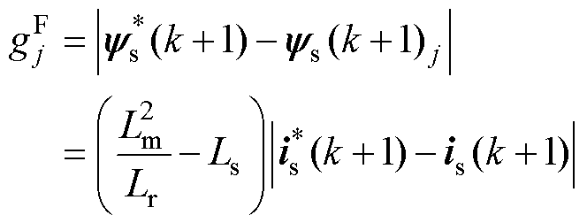
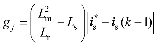
根据1.4节的推导,可以得到以定子磁链跟踪误差为优化目标的代价函数式为
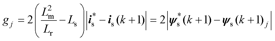 (22)
(22)
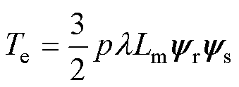
基于感应电机的电磁转矩方程式(15),代价函数式(22)等价于代价函数,有
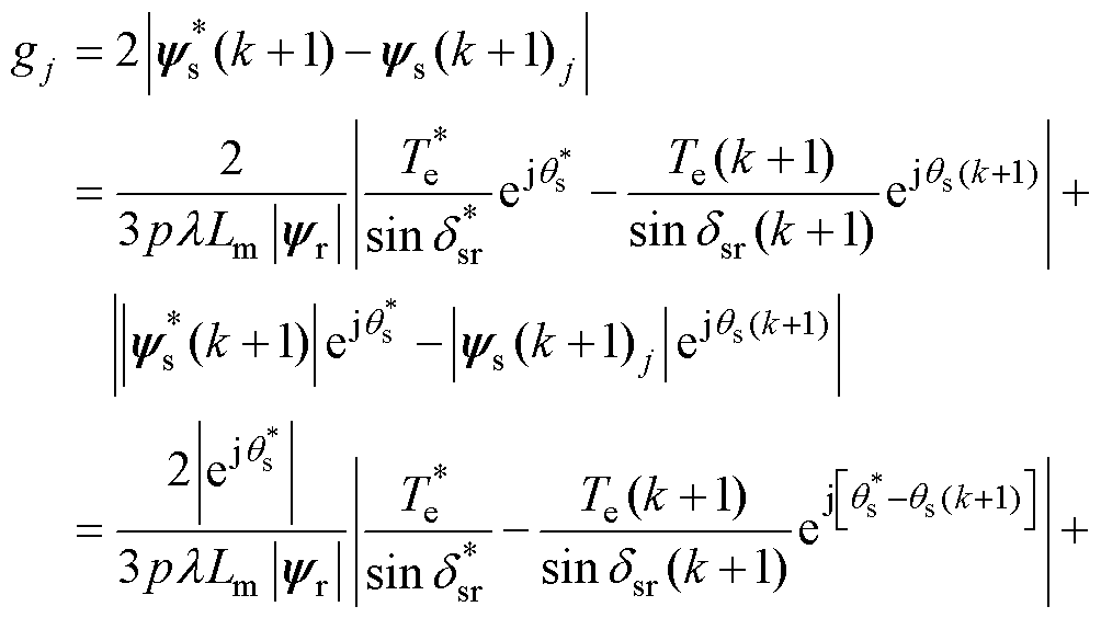
 (23)
(23)
其中
式中, 为转子磁链幅值,设定为额定转速内的额定值;
 为电磁转矩参考值;
 为定子磁链与转子磁链的角度差参考值。与定子电流和定子磁链相比,转子磁链的响应较慢,因此可以认为其在一个控制周期内基本不变。已知
 、
、 ,因此,代价函数式(23)可以被简化成
 (24)
(24)
可以看出,该代价函数以电磁转矩和定子磁链幅值作为优化目标。
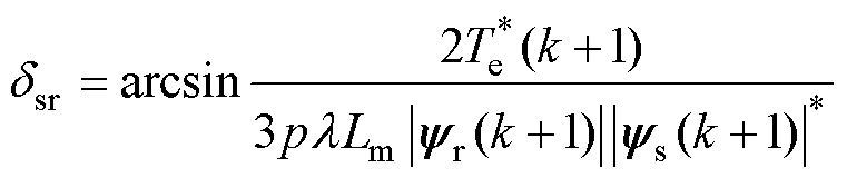
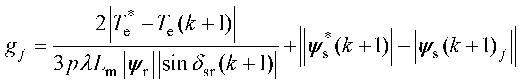
通过以上推导,FCS-MPTC的新型解析权重因子 计算设计为
计算设计为
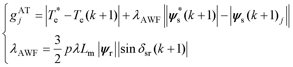 (25)
(25)
式中, 为权重因子,根据感应电机的参数计算得出;
 为定子磁链和转子磁链的差值,用于表征感应电机的状态。因此,与传统的FCS- MPTC相比,新型权重因子并非常数,而是随IM的工作状态而变化。
AWF-MPTC和MPTC的定子电流THD、定子磁链RMS和电磁转矩RMS如图4所示。图4中,AWF-MPTC采用解析权重因子 ,而MPTC采用评级法确定权重因子,
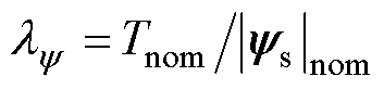 。图4表明,与MPTC相比,所提出的AWF-MPTC有效地降低了定子磁链RMS和定子电流THD,而电磁转矩RMS仅略有增加。
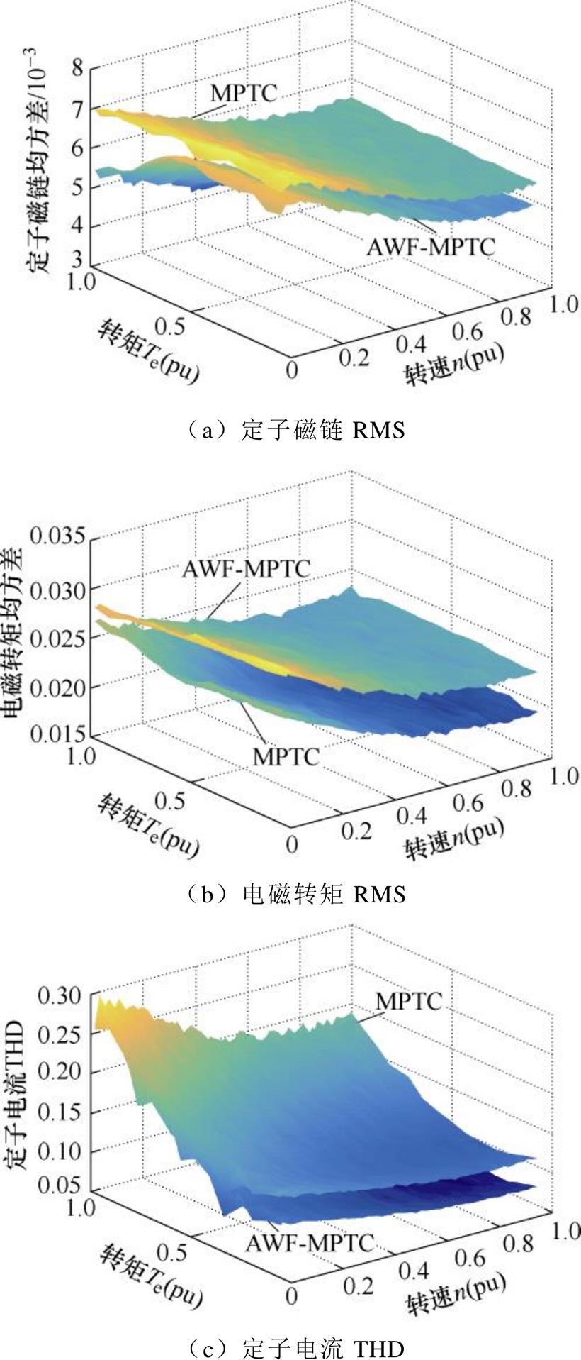
图4 AWF-MPTC和MPTC的定子电流THD、定子磁通RMS和电磁转矩RMS
Fig.4 Stator current THD, stator flux RMS and electromagnetic torque RMS of AWF-MPTC and MPTC
在AWF-MPTC中,可以看出,权重因子是通过解析方程计算的,其中包含感应电机的参数。但是,磁路饱和会导致励磁电感 增大,温升会导致电阻增大。IM的参数不匹配会使权重因子的计算不准确。失配的AWF-MPTC的定子电流THD、定子磁链RMS和电磁转矩RMS如图5所示。图中,
 、
、 为漏感和失配的漏感,
 为失配的励磁电感。
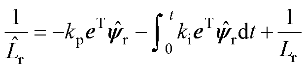
为了提高权重因子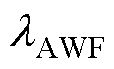 的准确性,提出了一种励磁电感估计器,该估计器结合了新的解析权重因子的计算。在静止的
 参考系中,转子磁链方程为


图5 参数失配的AWF-MPTC的定子电流THD、定子磁链RMS和电磁转矩RMS
Fig.5 Stator current THD, stator flux RMS and electromagnetic torque RMS of AWF-MPTC with mismatched parameters
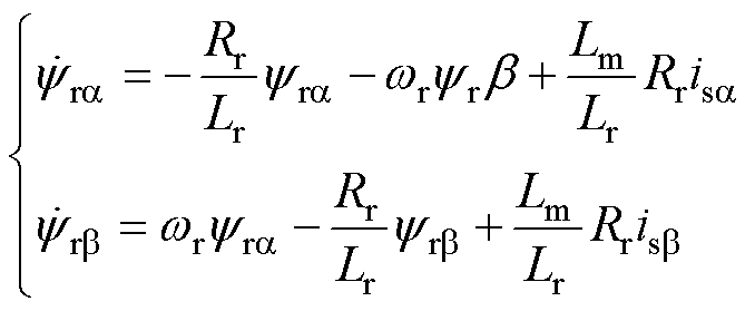 (26)
(26)
式中, 和
和 分别为参考系中的定子磁链
 、
、 轴分量;
轴分量; 和
和 为定子电流、轴分量。
励磁电感的观测器方程可以表示为
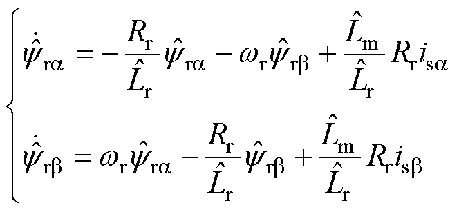 (27)
(27)
式中, 和
和 为估计的励磁电感和转子电感。已知
 ,
, 为转子的漏磁电感,远小于励磁电感,一般认为是常数。
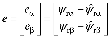
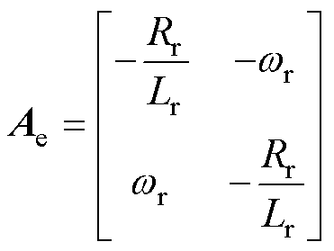
用式(26)减去式(27),可以得到转子磁链的误差方程为
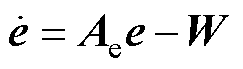 (28)
(28)
其中
为了估计励磁电感,本文中的自适应方案设计为
 (29)
(29)
式中, 和
和 分别为比例系数和积分系数,根据波波夫超稳定理论设置。
励磁电感为
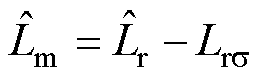 (30)
(30)
AWF-MPTC的算法总体框图如图6所示,本文利用新型的解析权重因子来获得基于IM工况的最佳电压矢量。电感参数在线辨识不仅提高了解析权重因子的计算精度,而且提高了预测模型的精度。

图6 算法总体框图
Fig.6 The block diagram of the proposed algorithm
本文所提出的用于感应电机驱动的AWF-MPTC在如图7所示的实验平台上进行了验证。感应电机由数字信号处理器(TMS320F28335)控制,而永磁同步电机由丹佛斯变频器提供负载转矩。感应电机参数如下: ,
, ,
, ,
, ,
, ,额定频率
,额定频率 ,额定功率
,额定功率 。
。

图7 实验平台
Fig.7 The experimental platform
所提出的AWF-MPTC和传统模型预测转矩控制(Traditional MPTC, T-MPTC)的动态性能分别如图8和图9所示。速度指令设置为2 772 r/min,然后在1.0 s时变为-2 772 r/min。图中,ia为A相定子电流。从图8和图9可以看出,AWF-MPTC和传统MPTC的电磁转矩响应都较快,这是因为模型预测控制直接通过成本函数而不是PI调节器选择最优电压矢量。另一方面,与传统的MPTC相比,AWF-MPTC具有较小的定子电流THD和电磁转矩脉动。

图8 AWF-MPTC的动态性能
Fig.8 The dynamic-state performances of AWF-MPTC for induction machine drives

图9 T-MPTC的动态性能
Fig.9 The dynamic-state performances of T-MPTC for induction machine drives
带参数辨识T-MPTC和AWF-MPTC的稳态性能如图10所示。带参数辨识T-MPTC在0.5 s时切换到AWF-MPTC。AWF-MPTC的定子电流THD为11.36%,而带参数辨识T-MPTC的定子电流THD为15.63%。带参数辨识T-MPTC的定子磁链脉动为0.1 Wb,而AWF-MPTC为0.065 Wb,降低了35%。
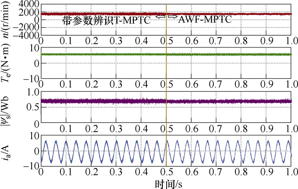
图10 AWF-MPTC和带参数辨识T-MPTC的稳态性能
Fig.10 The steady performance of AWF-MPTC and T-MPTC with parameter identification
AWF-MPTC和T-MPTC的稳态性能如图11所示。其中,AWF-MPTC的定子电流THD为11.52%,而T-MPTC定子电流THD为16.13%。T-MPTC定子磁链脉动为0.12Wb,而AWF-MPTC为0.068 Wb。
T-MPTC和AWF-MPTC的鲁棒性能分别如图12和图13所示。 和
和 为实际的电机参数,
 和
和 为相应的失配参数,用于AWF-MPTC和T-MPTC的预测控制。
 时,T-MPTC的定子电流THD为15.76%,而AWF-MPTC仅为11.29%。当
 时,AWF-MPTC的定子电流THD为12.15%,比传统的T-MPTC低31.5%。鲁棒性性能提高主要有两个原因:一是解析权重因子计算方法实现了电磁转矩和定子磁链的协调控制;二是感应电机参数的在线辨识不仅提高了预测模型的准确性,而且提高了权重因子的准确性。

图11 T-MPTC和AWF-MPTC的稳态性能
Fig.11 The steady performance of T-MPTC and AWF-MPTC
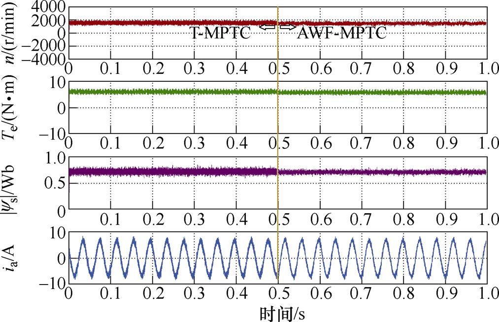
图12  时T-MPTC和AWF-MPTC鲁棒性
Fig.12 The robustness performance of T-MPTC and AWF-MPTC with for induction machine drives
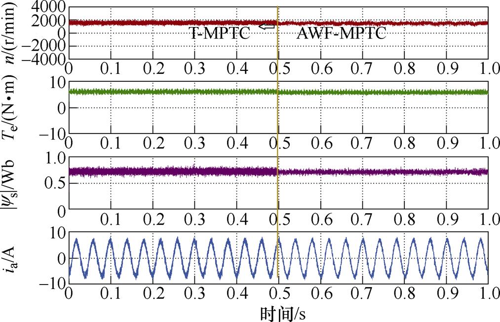
图13  时T-MPTC和AWF-MPTC鲁棒性
Fig.13 The robustness performance of T-MPTC and AWF-MPTC with for induction machine drives
表1总结了本文所提出AWF-MPTC与传统T- MPTC的各项实验性能对比。可以看出,本文所提出的AWF-MPTC各项性能均优于传统的T-MPTC。
表1 AWF-MPTC和T-MPTC的实验性能对比
Tab.1 Experimental performance comparison of AWF-MPTC and T-MPTC
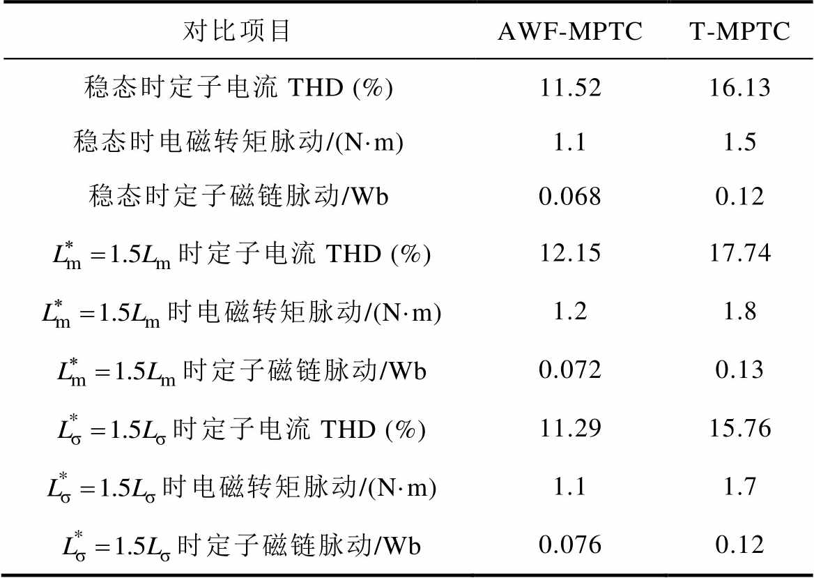
对比项目AWF-MPTCT-MPTC 稳态时定子电流THD (%)11.5216.13 稳态时电磁转矩脉动/(N·m)1.11.5 稳态时定子磁链脉动/Wb0.0680.12 时定子电流THD (%)12.1517.74 时电磁转矩脉动/(N·m)1.21.8 时定子磁链脉动/Wb0.0720.13 时定子电流THD (%)11.2915.76 时电磁转矩脉动/(N·m)1.11.7 时定子磁链脉动/Wb0.0760.12
在感应电机的FCS-MPTC中,代价函数中的权重因子是协调电磁转矩和定子磁链控制的关键参数。本文在分析感应电机内部电磁关系的基础上,提出了一种权重因子的解析计算方法。研究了电机参数失配对权重因子解析计算公式的影响机理,提出了一种基于在线参数辨识的权重因子解析计算方法,提高了预测模型的准确性。实验结果表明,与传统MPTC相比,所提出的AWF-MPTC具有更好的动态性能、稳态性能和鲁棒性能。在不同工况下,实现了电磁转矩和定子磁链的优化协调控制。
参考文献
[1] 夏长亮, 方红伟. 永磁无刷直流电机及其控制[J]. 电工技术学报, 2012, 27(3): 25-34.
Xia Changliang, Fang Hongwei. Permanent-magnet brushless DC motor and its control[J]. Transactions of China Electrotechnical Society, 2012, 27(3): 25-34.
[2] De Klerk M L, Saha A K. A comprehensive review of advanced traction motor control techniques suitable for electric vehicle applications[J]. IEEE Access, 2021, 9: 125080-125108.
[3] Sun Yuanxiang, Li Zhen, Zhang Zhenbin. Hybrid predictive control with simple linear control based circulating current suppression for modular multilevel converters[J]. CES Transactions on Electrical Machines and Systems, 2019, 3(4): 335-341.
[4] Zhu Z Q, Cai S. Hybrid excited permanent magnet machines for electric and hybrid electric vehicles[J]. CES Transactions on Electrical Machines and Systems, 2019, 3(3): 233-247.
[5] 赵凯辉, 周瑞睿, 冷傲杰, 等. 一种永磁同步电机的有限集无模型容错预测控制算法[J]. 电工技术学报, 2021, 36(1): 27-38.
Zhao Kaihui, Zhou Ruirui, Leng Aojie, et al. Finite control set model-free fault-tolerant predictive control for permanent magnet synchronous motor[J]. Transa- ctions of China Electrotechnical Society, 2021, 36(1): 27-38.
[6] 滕青芳, 李国飞, 朱建国, 等. 三相四开关容错逆变器的PMSM驱动系统FCS-MPC策略[J]. 电机与控制学报, 2016, 20(10): 15-22.
Teng Qingfang, Li Guofei, Zhu Jianguo, et al. Finite- control-set model predictive control for PMSM systems driven by three-phase four-switch fault- tolerant inverter[J]. Electric Machines and Control, 2016, 20(10): 15-22.
[7] 史婷娜, 杨雨要, 周湛清, 等. 基于二次型价值函数的双电机转矩同步系统有限集模型预测控制[J]. 中国电机工程学报, 2019, 39(15): 4531-4541.
Shi Tingna, Yang Yuyao, Zhou Zhanqing, et al. FCS-MPC for dual-motor torque synchronization system based on quadratic form cost function[J]. Proceedings of the CSEE, 2019, 39(15): 4531-4541.
[8] Khalilzadeh M, Vaez-Zadeh S, Rodriguez J, et al. Model-free predictive control of motor drives and power converters: a review[J]. IEEE Access, 2021, 9: 105733-105747.
[9] 陈卓易, 屈稳太, 邱建琪. 一种开关频率可控的有限集模型预测控制[J]. 电工技术学报, 2022, 37(16): 4134-4142.
Chen Zhuoyi, Qu Wentai, Qiu Jianqi. A switching- frequency-controlled finite-control-set model predictive control method[J]. Transactions of China Electro- technical Society, 2022, 37(16): 4134-4142.
[10] Rodriguez J, Garcia C, Mora A, et al. Latest advances of model predictive control in electrical drives-part II: applications and benchmarking with classical control methods[J]. IEEE Transactions on Power Electronics, 2022, 37(5): 5047-5061.
[11] Vazquez S, Rodriguez J, Rivera M, et al. Model predictive control for power converters and drives: advances and trends[J]. IEEE Transactions on Indu- strial Electronics, 2017, 64(2): 935-947.
[12] 宋文胜, 郭永琪, 余彬, 等. 五相永磁同步电机全速度范围占空比优化模型预测电流控制[J]. 中国电机工程学报, 2022, 42(12): 4561-4571.
Song Wensheng, Guo Yongqi, Yu Bin, et al. A model predictive current control of five-phase PMSM with duty ratio optimization in whole speed range[J]. Proceedings of the CSEE, 2022, 42(12): 4561-4571.
[13] Yan Liming, Wang Fengxiang, Dou Manfeng, et al. Active disturbance-rejection-based speed control in model predictive control for induction machines[J]. IEEE Transactions on Industrial Electronics, 2020, 67(4): 2574-2584.
[14] 史涔溦, 马红如, 陈卓易, 等. 永磁同步电机模糊代价函数预测转矩控制[J]. 电机与控制学报, 2022, 26(1): 1-8.
Shi Cenwei, Ma Hongru, Chen Zhuoyi, et al. Fuzzy tuning of weight coefficient in model predictive torque control of PMSM[J]. Electric Machines and Control, 2022, 26(1): 1-8.
[15] 刘涛, 习金玉, 宋战锋, 等. 基于多核并行计算的永磁同步电机有限集模型预测控制策略[J]. 电工技术学报, 2021, 36(1): 107-119.
Liu Tao, Xi Jinyu, Song Zhanfeng, et al. Finite control set model predictive control of permanent magnet synchronous motor based on multi-core parallel computing[J]. Transactions of China Electro- technical Society, 2021, 36(1): 107-119.
[16] Wang Fengxiang, Xie Haotian, Chen Qing, et al. Parallel predictive torque control for induction machines without weighting factors[J]. IEEE Transa- ctions on Power Electronics, 2020, 35(2): 1779- 1788.
[17] 柳志飞, 杜贵平, 杜发达. 有限集模型预测控制在电力电子系统中的研究现状和发展趋势[J]. 电工技术学报, 2017, 32(22): 58-69.
Liu Zhifei, Du Guiping, Du Fada. Research status and development trend of finite control set model predictive control in power electronics[J]. Transa- ctions of China Electrotechnical Society, 2017, 32(22): 58-69.
[18] Zhang Yongchang, Yang Haitao, Xia Bo. Model- predictive control of induction motor drives: torque control versus flux control[J]. IEEE Transactions on Industry Applications, 2016, 52(5): 4050-4060.
[19] Hu Yuansheng, Hu Cungang, Zhang Pinjia, et al. A novel hybrid seven-level converter for permanent magnet synchronous motor driving system based on model predictive control[J]. CES Transactions on Electrical Machines and Systems, 2019, 3(4): 389- 396.
[20] Zhang Kai, Fan Mingdi, Yang Yong, et al. Tolerant sequential model predictive direct torque control of permanent magnet synchronous machine drives[J]. IEEE Transactions on Transportation Electrification, 2020, 6(3): 1167-1176.
[21] Rojas C A, Rodriguez J R, Kouro S, et al. Multiobjective fuzzy-decision-making predictive torque control for an induction motor drive[J]. IEEE Transactions on Power Electronics, 2017, 32(8): 6245-6260.
[22] Novak M, Xie Haotian, Dragicevic T, et al. Optimal cost function parameter design in predictive torque control (PTC) using artificial neural networks (ANN)[J]. IEEE Transactions on Industrial Elec- tronics, 2021, 68(8): 7309-7319.
[23] 李家祥, 汪凤翔, 柯栋梁, 等. 基于粒子群算法的永磁同步电机模型预测控制权重系数设计[J]. 电工技术学报, 2021, 36(1): 50-59, 76.
Li Jiaxiang, Wang Fengxiang, Ke Dongliang, et al. Weighting factors design of model predictive control for permanent magnet synchronous machine using particle swarm optimization[J]. Transactions of China Electrotechnical Society, 2021, 36(1): 50-59, 76.
[24] 张虎, 张永昌, 夏波, 等. 基于空间矢量调制的感应电机无速度传感器模型预测磁链控制[J]. 电工技术学报, 2017, 32(3): 97-104.
Zhang Hu, Zhang Yongchang, Xia Bo, et al. Speed sensorless model predictive flux control of induction motor drives based on space vector modulation[J]. Transactions of China Electrotechnical Society, 2017, 32(3): 97-104.
[25] 谢昊天, 汪凤翔, 柯栋梁, 等. 基于集成优化的感应电机无权重系数预测转矩控制[J]. 电工技术学报, 2022, 37(12): 2992-3003.
Xie Haotian, Wang Fengxiang, Ke Dongliang, et al. Ensemble optimization based weighting factor-less predictive torque control for induction machines[J]. Transactions of China Electrotechnical Society, 2022, 37(12): 2992-3003.
[26] 张瑞林, 卢子广, 甘霖, 等. 感应电机无权重系数模型预测转矩控制[J]. 电气传动, 2020, 50(10): 102-106.
Zhang Ruilin, Lu Ziguang, Gan Lin, et al. Model predictive torque control of induction motor without weighting factor[J]. Electric Drive, 2020, 50(10): 102-106.
[27] 颜黎明, 赵冬冬, 焦宁飞. 基于鲁棒模型的航空交流感应电机预测转矩控制[J]. 航空学报, 2021, 42(9): 462-472.
Yan Liming, Zhao Dongdong, Jiao Ningfei. Robust model based-predictive torgue control of aviation AC induction motor[J]. Acta Aeronautica et Astronautica Sinica, 2021, 42(9): 462-472.
[28] 尹华杰, 郭志宇, 曾君. 滑模无速度传感器感应电机的简化预测转矩控制[J]. 华南理工大学学报(自然科学版), 2020, 48(12): 18-26.
Yin Huajie, Guo Zhiyu, Zeng Jun. Simplified predictive torque control for induction motor with sliding mode speed-sensorless[J]. Journal of South China University of Technology (Natural Science Edition), 2020, 48(12): 18-26.
Abstract Finite control set-model predictive torque control (FCS-MPTC), using electromagnetic torque and stator flux as control variables, has recently receivedextensive attention in electric drive systems. It has the advantages of fast transient response of electromagnetic torque and ease of handling field weakening control. However, the weighting factor allocation of the FCS-MPTC cost function has always been a research challenge in the academic community. Since the essence of FCS-MPTC is the exhaustive method of discrete voltage vectors, the setting of the weight factor also needs a more theoretical basis. The rating method and cut-and-trial method are two classical weighting factor design strategies. The rating method sets the weighting factor as the ratio of rated electromagnetic torque to rated stator flux amplitude. This method can realize the coordinated control of electromagnetic torque and stator flux under the rated condition of IM, but the control performance is poor under other conditions. The cut-and-trial method obtains the weighting factor configuration through repeated online debugging, which can be more convenient and easier to obtain optimal control.
Firstly, the influence mechanism of different weighting factors on stator current total harmonic distortion (THD) of stator current, root mean square (RMS) of electromagnetic torque, and RMS of stator flux linkage is studied. The results show that with the increase of the weighting factor, the stator flux RMS decreases, the electromagnetic torque RMS is just the opposite, and the stator current THD decreases first and then increases. Secondly, the stator current THD, RMS of electromagnetic torque, and RMS of stator flux linkage of the motor under different operating conditions with a fixed weighting factor are studied. The results show that when the induction motor (IM) FCS-MPTC operates at low speed, the performances of stator flux RMS and electromagnetic torque RMS worsen. For the induction motor FCS-MPTC under low speed and light load, the stator current THD exhibits large harmonics. Then, the mathematical expression of the weighting factor is derived analytically according to the internal relations of electromagnetic relations of IM, which can achieve multi-objective optimal control of induction motors under different working conditions. Because the analytical expression of the weighting factor depends on the motor parameters, this paper integrates the online parameter identification technology, which can achieve the calculation accuracy of the weighting factor and the prediction model. The proposed analytical weighting factor-model predictive torque control (AWF-MPTC) has a smaller stator current THD and electromagnetic torque ripple than traditional MPTC (T-MPTC). In steady states, the stator current THD of AWF-MPTC is 11.52%, while that of T-MPTC is 16.13%. T-MPTC stator flux ripple is 0.12 Wb, while AWF-MPTC is 0.068 Wb. At the same time, AWF-MPTC has better robustness than T-MPTC. There are two main reasons for the improvement of robustness performance. Firstly, the analytical weighting factor calculation method realizes the coordinated control of electromagnetic torque and stator flux. Secondly, the online identification of induction motor parameters improves the accuracy of the prediction model and the weighting factor.
Compared with T-MPTC, the proposed AWF-MPTC has better dynamic performance, steady performance, and robustness. Under different operating conditions, the optimal coordinated control of electromagnetic torque and stator flux is realized.
keywords:Model predictive control, induction motor, predictive torque control, weighting factor, cost function
DOI: 10.19595/j.cnki.1000-6753.tces.221465
中图分类号:TM346
国家自然科学基金(52107036)、中国博士后科学基金特别资助(2022T150071)、陕西省创新能力支撑计划(2021TD-28)、陕西省自然科学基础研究计划(2021JQ-252)和中央高校基本科研业务费(自然科学类)(300102223201)资助项目。
收稿日期 2022-07-29
改稿日期 2022-09-23
颜黎明 男,1988年生,讲师,硕士生导师,研究方向为电动汽车电机驱动和充电技术等。E-mail: ylm@chd.edu.cn(通信作者)
郭 鑫 男,1998年生,硕士研究生,研究方向电动汽车驱动电机的模型预测控制。E-mail: gxlocas@163.com
(编辑 崔文静)