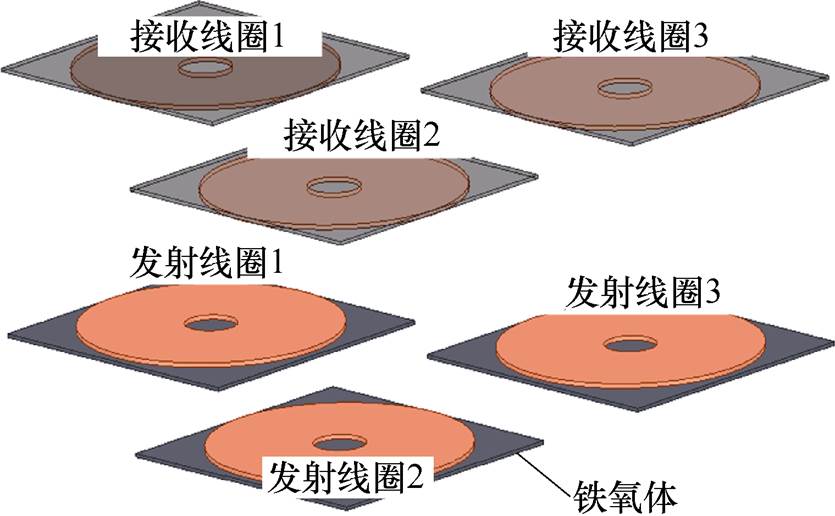
图1 三线圈WPT系统耦合机构
Fig.1 Coupling mechanism of the three coils WPT system
摘要 针对多线圈的单管无线电能传输系统提出一种P#型LCC-S补偿网络和输入电流纹波抑制方法,以改善输入电流波形、降低输入电流THD及纹波,从而提高系统效率。该文首先分析P#型LCC-S补偿网络的工作模态和波形,同时给出P#型LCC-S补偿网络参数的计算方法;其次推导了三线圈在非均衡耦合情况下输入电流与输入电压、线圈互感、负载阻抗等参数间的解析关系,利用傅里叶变换分析了输入电流的构成,并对交流分量进行移相抑制;最后搭建实验平台并进行相关实验验证。实验结果表明,在额定传输功率下,纹波抑制后系统效率最高达88.2 %,验证了该方案的有效性。
关键词:无线电能传输 LCC-S补偿网络 纹波抑制 单管谐振逆变
无线电能传输(Wireless Power Transfer, WPT)技术可以使能量通过气隙传输,而不需要物理接 触[1],具有安全、快捷及灵活等优势,被认为是代替电缆充电的最好选择[3],已被应用于消费电子、电动汽车、特种机械以及医疗电子等设备的供电[2]。
在无线电能传输技术研究中,针对多线圈并联传输的研究多数基于全桥或半桥拓扑,但均存在控制及外围电路复杂、桥臂直通等问题。相比之下,单管谐振逆变电路具有可靠性高、控制简单、成本低、易于实现零电压开通等优点,但存在传输功率有限以及系统输入电流纹波大等不足。因此通过并联多个发射端并通过控制系统输入电流的角度对纹波进行抑制,同时增大传输功率,此举是克服单管谐振逆变器不足的有效方式。在相同传输功率下,整个系统的控制方案相对于全桥拓扑更加简单。文献[9]提出了一种主从相位同步控制的并联逆变器拓扑结构,但辅助逆变器仅用于调谐。文献[10]基于全桥逆变器提出了一种输入并联、输出串联WPT系统及其效率优化方法。文献[11]对单管LCC-S补偿网络的效率进行了优化,优化后系统输出功率为11 W,效率为86.3 %。文献[12]提出基于单管PP型谐振逆变器的无线电能传输电路,该电路利用SiC MOSFET,有效提高了系统效率,但未考虑系统输入电流对系统的影响。
由于单管谐振逆变器WPT系统的特殊性,常规的补偿拓扑无法直接应用。单管谐振逆变发射端的补偿网络通常为P型结构。其中,PP型和PS型的谐振频率由发射线圈自感Lt、接收线圈自感Lr、互感M及负载RL决定[12]。但耦合机构发生偏移时将导致互感M发生变化,使系统的谐振频率发生较大变化,从而影响整个系统的传输功率和效率。另外,P型补偿网络的电压增益和品质因数都较低,正常工作时的直流输入电压高,且系统对高次谐波的滤除效果较差。
LCC拓扑在正常工作时具有如下优点:①可以调节补偿网络参数使系统恒压输出。②系统的谐振频率仅与线圈自感有关,不受互感和负载变化的影响、系统工作时不易失谐[10]。③作为高阶网络,其品质因数较高,对高次谐波的滤除效果较好。另外,其电压增益可调,对输入电压等级要求低。
综上所述,本文针对多线圈的单管无线电能传输提出适用于单管谐振逆变器的P#型LCC-S补偿网络,并通过三线圈并联输入的方式增大系统的传输功率。为了改善系统输入电流的总谐波畸变率(Total Harmonic Distortion, THD),首先对比分析了不同谐振电路及参数的工作模态和系统输入电流波形,确定了P#型LCC-S补偿网络。其次,为了减小系统输入电流的纹波,推导了三线圈非均衡耦合情况下线圈输入电流与输入电压、线圈互感、负载阻抗等参数之间的关系式,对系统输入电流频域分析后获得基波和各次谐波的有效值,并对纹波进行移相抑制,以提高系统效率。经实验验证表明,在额定功率150 W情况下,通过采用移相抑制策略后,线圈耦合距离均在50 mm情况下系统输入电流的峰-峰值从8.7 A降至2.76 A;线圈耦合距离在40 mm、50 mm、60 mm情况下系统输入电流的峰-峰值从6.98 A降至1.6 A,最高效率为88.2 %。
三线圈WPT系统耦合机构如图1所示。发射线圈与接收线圈间距为50 mm、铁氧体的长、宽均为160 mm,厚度为2 mm,线圈采用0.1 mm×150股的利兹线绕制而成。

图1 三线圈WPT系统耦合机构
Fig.1 Coupling mechanism of the three coils WPT system
系统电路如图2所示。Vdc为系统输入直流电压;Q1~Q3为MOSFET开关管;Lf1~Lf3为发射端补偿电感;Cf1~Cf3为发射端并联补偿电容;Lt1~Lt3为发射线圈电感;Ct1~Ct3为发射端串联补偿电容;Rt1~Rt3为发射线圈内阻;La1~La3为谐振电感;Ca1~Ca3为谐振电容;M1~M3为耦合线圈间互感;Lr1~Lr3为接收线圈电感;Rr1~Rr3为接收线圈内阻;Cr1~Cr3为接收线圈的补偿电容;VD1~VD3为整流桥;CL1~CL3为输出滤波电容;RL为负载电阻。 ~
~ 为每个逆变器的输入电流;
 ~
~ 为发射端补偿电感电流;
 ~
~ 为发射线圈激励电流;
 ~
~ 接收线圈输出电流;
 ~
~ 为整流桥输入电压;IL为负载电流;VL为负载电压。每个整流器后级联DC-DC变换器用来解决输出电压不相等造成的环流影响。
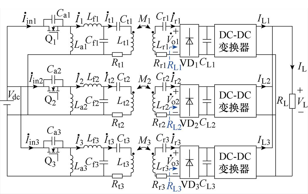
图2 三线圈并联WPT系统电路
Fig.2 The WPT system with three coils parallel
由于单管谐振逆变器的特殊性,常规的LCC谐振网络无法直接应用。可以通过在发射端额外加入LC谐振电路进行谐振,LCC补偿网络作为补偿电路,如图3a所示,使系统具备LCC补偿网络的特点。此外,LC谐振电路还起到调节软开关裕量的作用。但由于传统单管LCC补偿网络的系统输入电流畸变严重,如图4a所示。因此本文在传统LCC补偿网络基础上,提出了一种适用于单管谐振逆变器的P#型LCC补偿网络,如图3b所示,该电路谐振电容Ca与开关管并联,将系统输入端的电流振荡转移到地,如图4b所示,有效地改善了系统输入电流波形,减小了系统输入电流的THD,提高了系统效率。
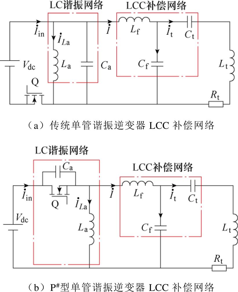
图3 基于单管谐振逆变器的LCC谐振网络
Fig.3 LCC resonant network based on single-switch resonance inverter
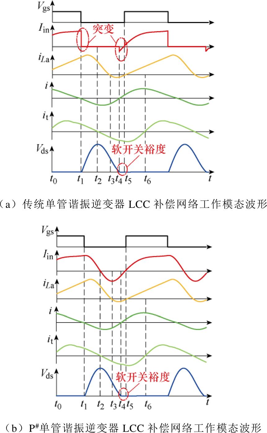
图4 两种补偿网络工作模态对比
Fig.4 Comparison of operating modal of two compensation networks
如图3所示,整个补偿网络可分为LC谐振网络和LCC补偿网络两个部分。为了方便分析,假设电路中各元器件为理想元件。不同谐振网络的系统工作模态波形如图4所示。图中Vgs为开关管的驱动电压, 为谐振电感电流,
 为发射端补偿电感电流,Vds为开关管漏源极电压。传统LC谐振网络理想状态下的工作模态如下。
模态一[t0, t1 :在t0时刻,开关管导通,谐振电感电流
 线性增加。谐振电容Ca等效短路,发射端补偿电感电流
 逐渐减小,在t1时刻过零。
模态二[t1, t2 :在t1时刻,开关管关断,输入电流
 迅速降至零,发射端补偿电感电流
 反向增加,发射线圈激励电流
 持续下降至零。
模态三[t2, t3 :在t2时刻,谐振电感电流
 减小至零,发射端补偿电感电流
 和发射线圈电流
 反向增加,Vds达到最大值。
模态四[t3, t4 :在t3时刻,谐振电感电流
 反向增加,发射端补偿电感电流
 减小至零。
减小至零。
模态五[t4, t5 :在t4时刻,系统输入电流
 快速反向增加后开始减小,谐振电感电流
 反向减小过零,发射端补偿电感电流
 过零后正向增加。Vds电压为零,开关管进入软开关状态。
模态六[t5, t6 :在t5时刻,开关管导通,系统输入电流
 、谐振电感电流
 和发射端补偿电感电流
 正向增加。发射线圈激励电流
 反向减小至零。
模态七[t6, t0 :在t6时刻,系统输入电流
 、谐振电感电流
 以及发射线圈激励电流
 正向 增加。
理想状态下,P#型LCC补偿网络工作模态如下。
模态一[t0, t1 :与传统LCC补偿网络的工作模态一相同,不在此过多赘述。
模态二[t1, t2 :在t1时刻,开关管关断,系统输入电流
 开始减小,发射端补偿电感电流
 反向增加,发射线圈激励电流it持续下降至零。
模态三[t2, t3 :在t2时刻,系统输入电流
 增至最大值,发射端补偿电感电流
 过零并反向增加,发射线圈激励电流it反向增加,Vds达到最大值。
模态四[t3, t4 :在t3时刻,系统输入电流
 反向减小,谐振电感电流
 反向增加,发射端补偿电感电流
 减小至零。
减小至零。
模态五[t4, t5 :在t4时刻,系统输入电流
 反向减小,谐振电感电流
 反向减小过零,发射端补偿电感电流
 过零后正向增加。Vds电压为零,开关管进入软开关状态。
模态六[t5, t6 :与传统LCC补偿网络的工作模态六相同。
模态七[t6, t0 :与传统LCC补偿网络的工作模态七相同。
两种补偿网络输入电流THD对比如图5所示。由图4和图5可知,两种不同补偿网络的工作差别仅体现在输入电流中,P#型单管谐振逆变器LCC补偿网络有效改善了系统输入电流波形,减小了输入电流的THD。
根据文献[22-23]中所述,单管谐振逆变的等效输入交流电压 波形如图6a所示。
 为周期性方波电压和正弦半波电压,根据面积等效法则,可将
 波形等效为图6b。
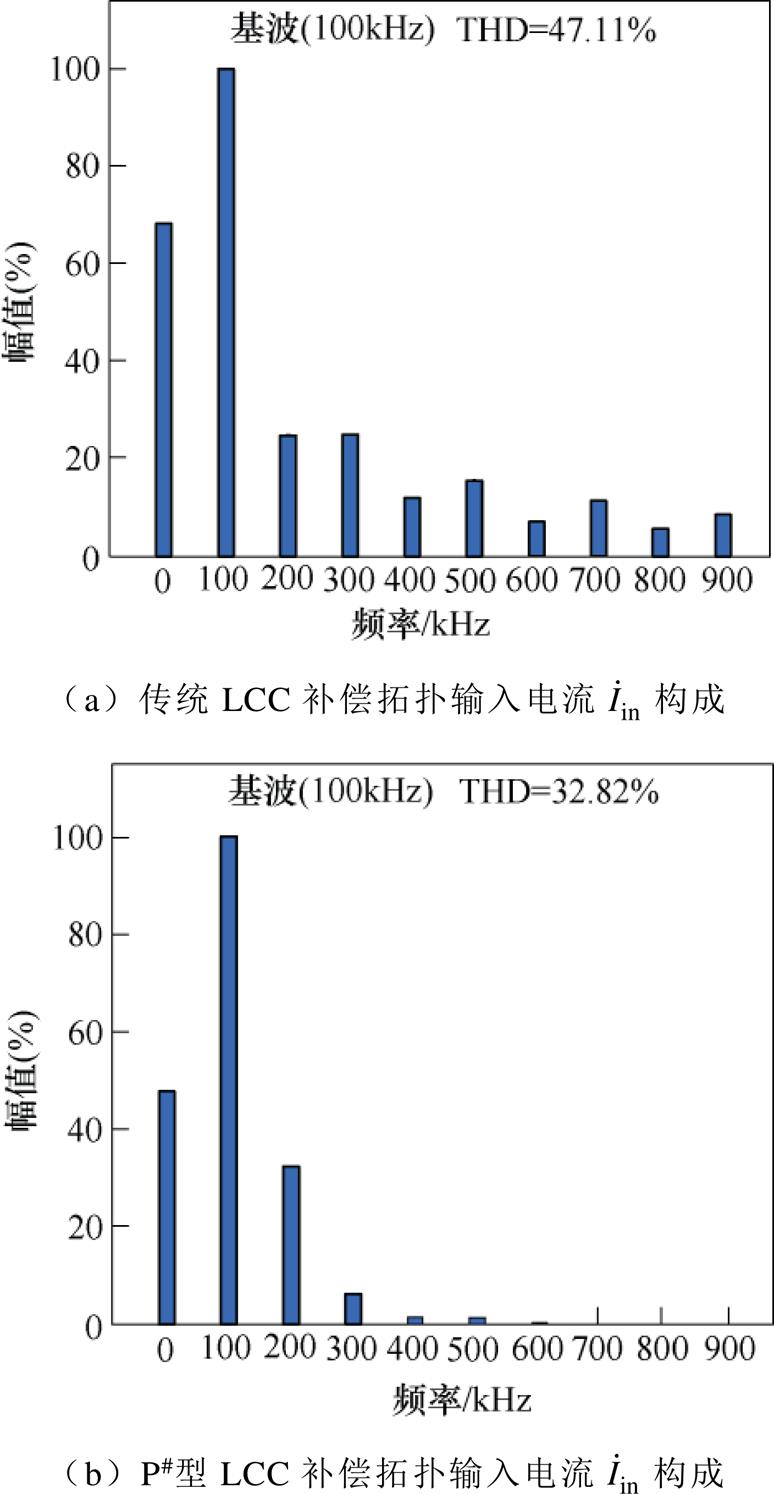
图5 本文所提两种补偿网络输入电流THD对比
Fig.5 THD comparison of input currents for two compensation networks
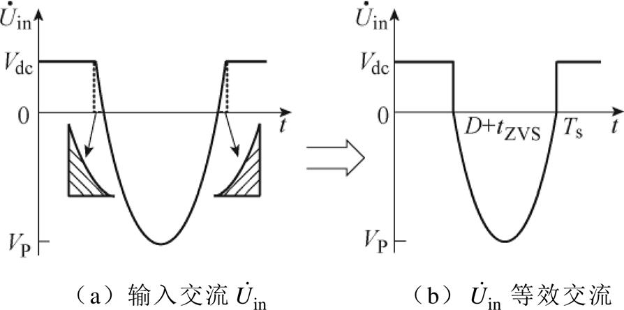
图6 LCC补偿网络等效输入交流电压 波形
波形
Fig.6 The equivalent input AC voltage  waveforms of the LCC compensation network
由图6b得出等效交流电压为
 (1)
(1)
式中,wn为角频率;D为占空比;tZVS为软开关裕量;VP为等效输入交流电压的峰值。
根据电感伏秒平衡,一个周期内电感电压为零,即
 (2)
(2)
解得
 (3)
(3)
每个子系统的输出阻抗可分别表示为
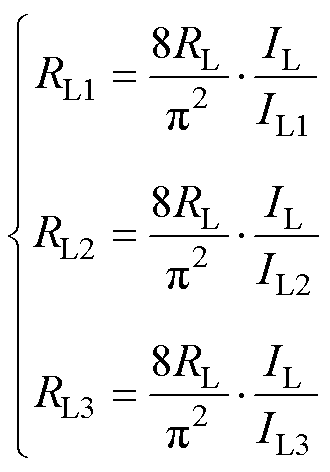 (4)
(4)
由于补偿网络良好的高阶滤波特性,系统可采用谐波近似法进行分析。系统等效电路如图7所示。为简化分析过程,当发射线圈间隔较远时,可忽略同侧线圈之间的交叉耦合[21]。
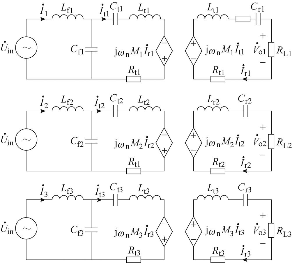
图7 LCC-S交流等效模型
Fig.7 AC equivalent model of LCC-S
根据LCC工作特性,当系统谐振时,输入阻抗Zin为纯阻性,即虚部为零时,存在如下[10]关系
 (5)
(5)
根据基尔霍夫电压定律,图7中LCC-S电路模型的KCL和KVL方程为
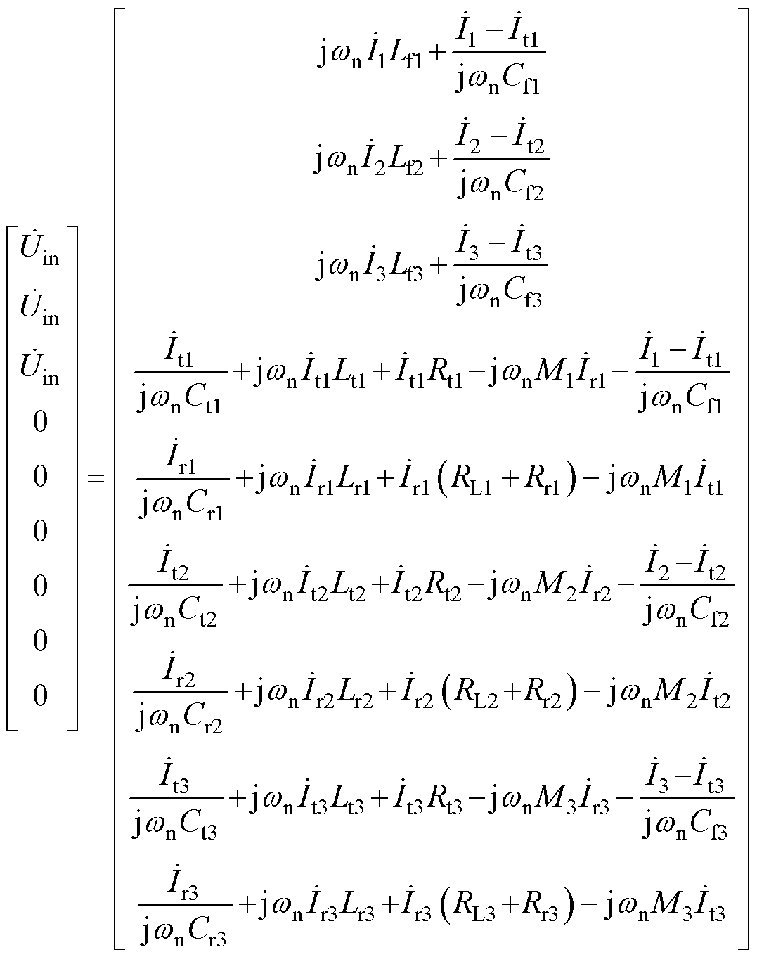 (6)
(6)
求得
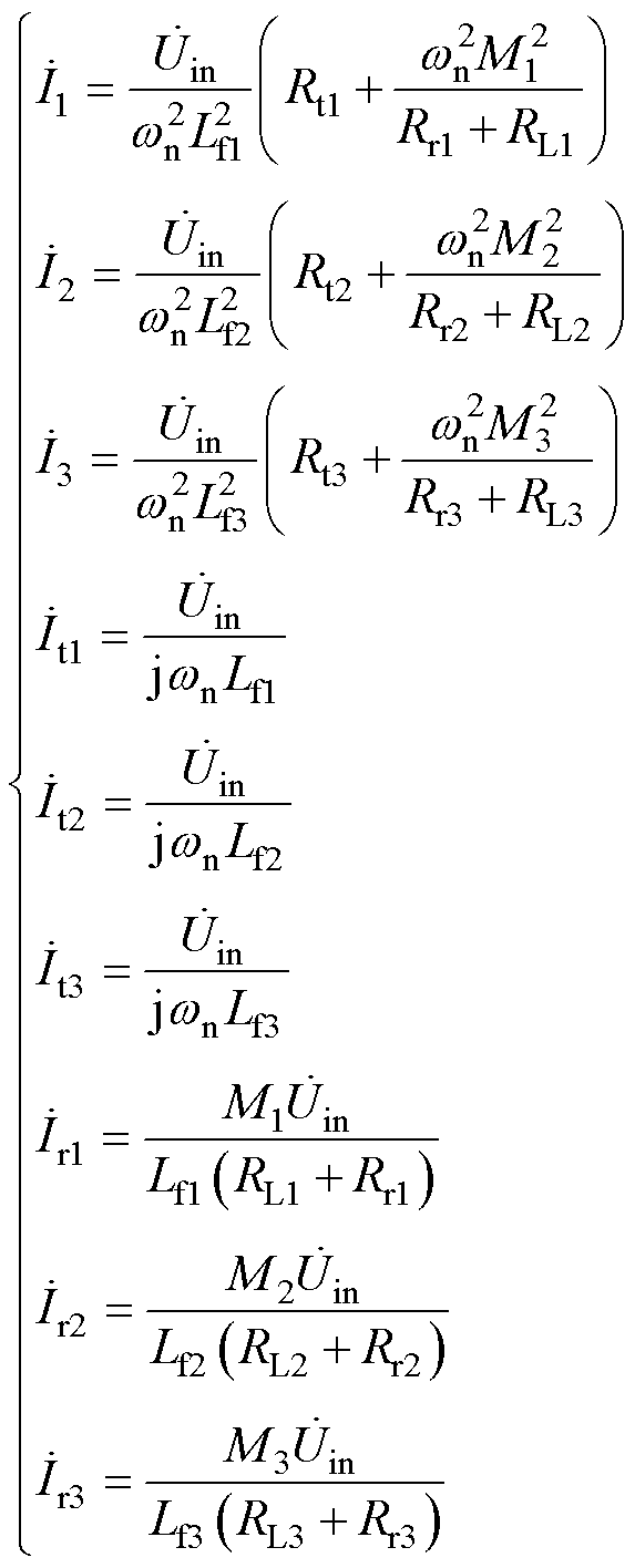 (7)
(7)
由式(7)可知,整流输入电压 、
、 和
和 分别为
分别为
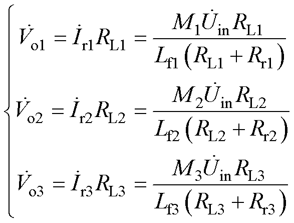 (8)
(8)
且 =
= =
= ,解得
,解得
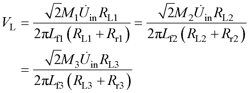 (9)
(9)
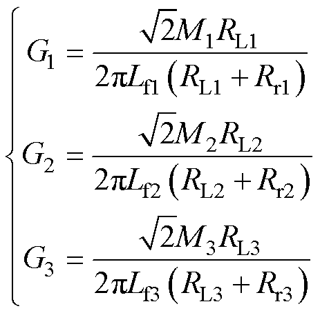
因此,各子系统电压增益G1、G2和G3分别为
 (10)
(10)
由式(10)可知,电压增益G与补偿电感Lf、互感M、负载和接收线圈内阻有关,因此,可降低补偿电感Lf提高电压增益,以降低输入电压等级。
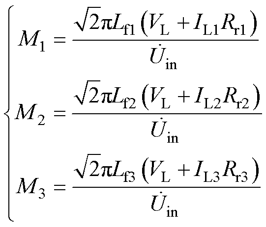
由式(4)、式(7)可得,互感M1、M2和M3分别为
 (11)
(11)
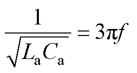
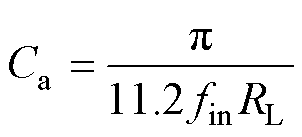
对于传统E类逆变电路只能在小范围负载内实现软开关,为了保持良好的软开关特性,需要根据负载情况和开关频率谐振电感电容La、Ca的参数。通常使谐振电感La、谐振电容Ca之间的输入谐振频率fin为开关频率f的1.3~1.5倍。即
 (12)
(12)
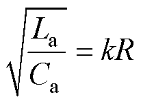
根据文献[24]中所述,谐振电感La、谐振电容Ca以及输出阻抗R的关系表示为
 (13)
(13)
式中,k的范围为0.2~1.5,而在本文的取值为0.7。因此,谐振电容Ca选择为
 (14)
(14)
谐振电感La选择为
 (15)
(15)
根据上述参数,求得开关管两端的电压波形如图8所示。
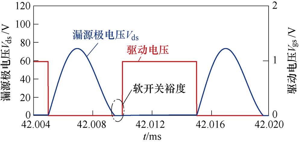
图8 软开关波形
Fig.8 Soft switching waveforms
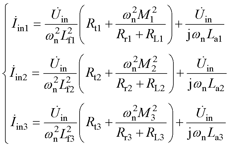
由式(7)可知,每相子系统输入电流 、
、 、
、 可分别表示为
 (16)
(16)
通过上述公式求得输入电流 后可利用傅里叶变换对输入电流
 分解,以求其直流分量Idc、基波分量以及各次谐波分量
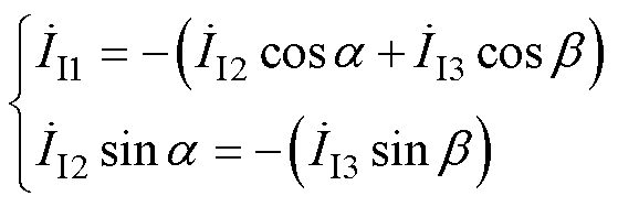
 。并按照式(17)所示的矢量分析对基波进行移相抑制。
 (17)
(17)
令子系统1的移相角为零,则a和b 分别为子系统2、子系统3的移相角。
根据式(17),以输入电压25 V,负载3.3 W,开关频率100 kHz,三线圈均衡耦合为例,移相前后输入电流 傅里叶分解后的谐波含量如图9a、图9b所示。图中Idc为输入电流
 的直流分量,
 为基波分量和各次谐波分量。对比移相前后的输入电流波形可知,移相后输入电流的谐波含量更小,电流更稳定。
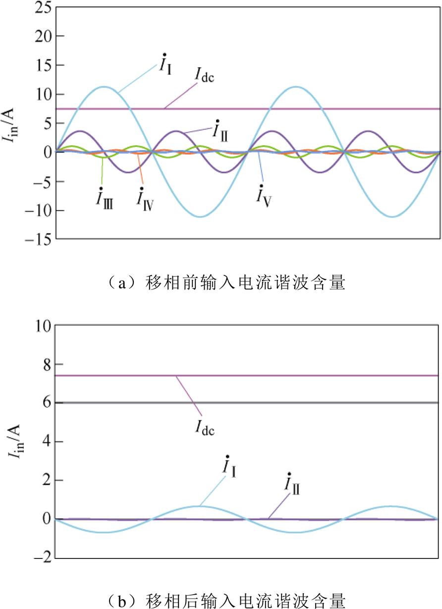
图9 输入电流谐波含量对比
Fig.9 Input current harmonic content comparison
系统控制电路如图10所示,在传输过程中,通过调整线圈移相导通角a、b 对直流源输出总电流控制,使总电流纹波最小,进而使整机效率更高。
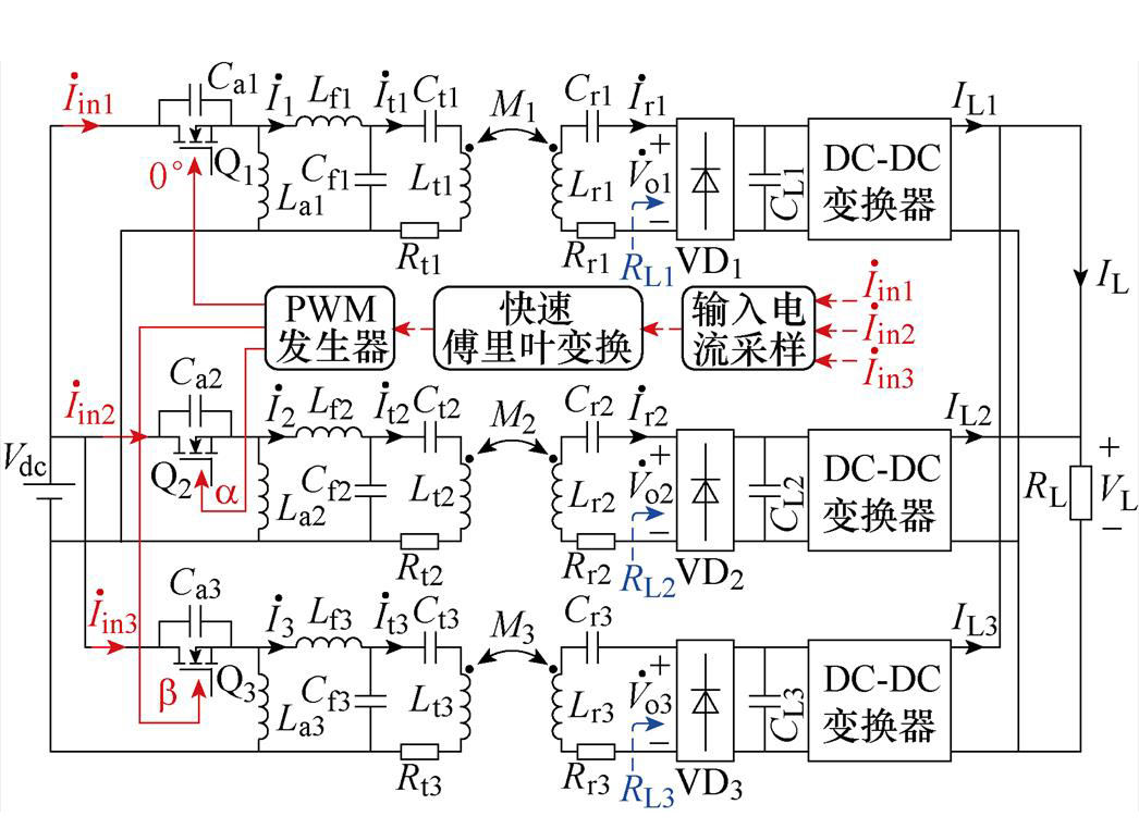
图10 控制电路示意图
Fig.10 Schematic diagram of control method
在实际系统中,选择一个单管无线电能传输子系统为基准,并令其导通角为0 °,剩下两个控制自由度a 和b 根据式(17)可求。
为了验证所提出方法的正确性,本文针对不同线圈数量进行理论分析和仿真验证。在子系统均衡耦合情况下,当系统为三线圈输入时需移相120 °,四线圈输入时需移相90 °,即在均衡耦合情况下每个开关管移相角度j 为
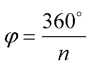 (18)
(18)
而在非均衡耦合情况下由于子系统间传输功率存在差异性,不能按照均衡耦合的移相方式进行移相。因此针对不同线圈的移相策略为:三线圈按照式(17)移相方式进行移相,当系统为多线圈时,每次选定输入电流最小的两相求和,经不断迭代计算,最终将输入电流化简为三相,即可按式(17)移相方式进行移相。
以四线圈为例,其互感为46.4 mH时,每相移相90 °导通,移相前后输入电流情况如图11a所示。当线圈互感分别为25、30、35、40 mH时,移相前后的仿真波形如图11b所示,在均衡耦合下移相前后输入电流波形改进明显,而在非均衡耦合情况下因移相角计算精度存在误差导致移相前后效果逊于均衡耦合,但也有较大改善。
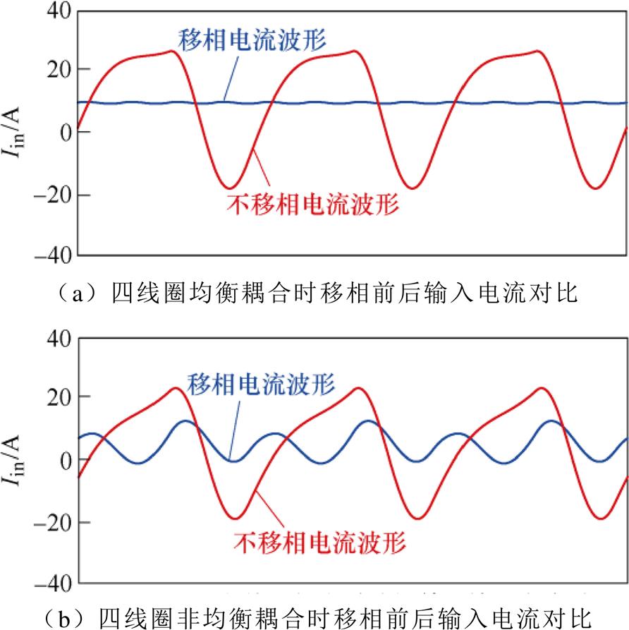
图11 四线圈移相前后输入电流对比
Fig.11 Input current comparison before and after phase shift of the four transmit coils
为了验证提出方法的有效性和可行性,本文对所提出的电路模型和控制方案进行了仿真分析和实物验证。
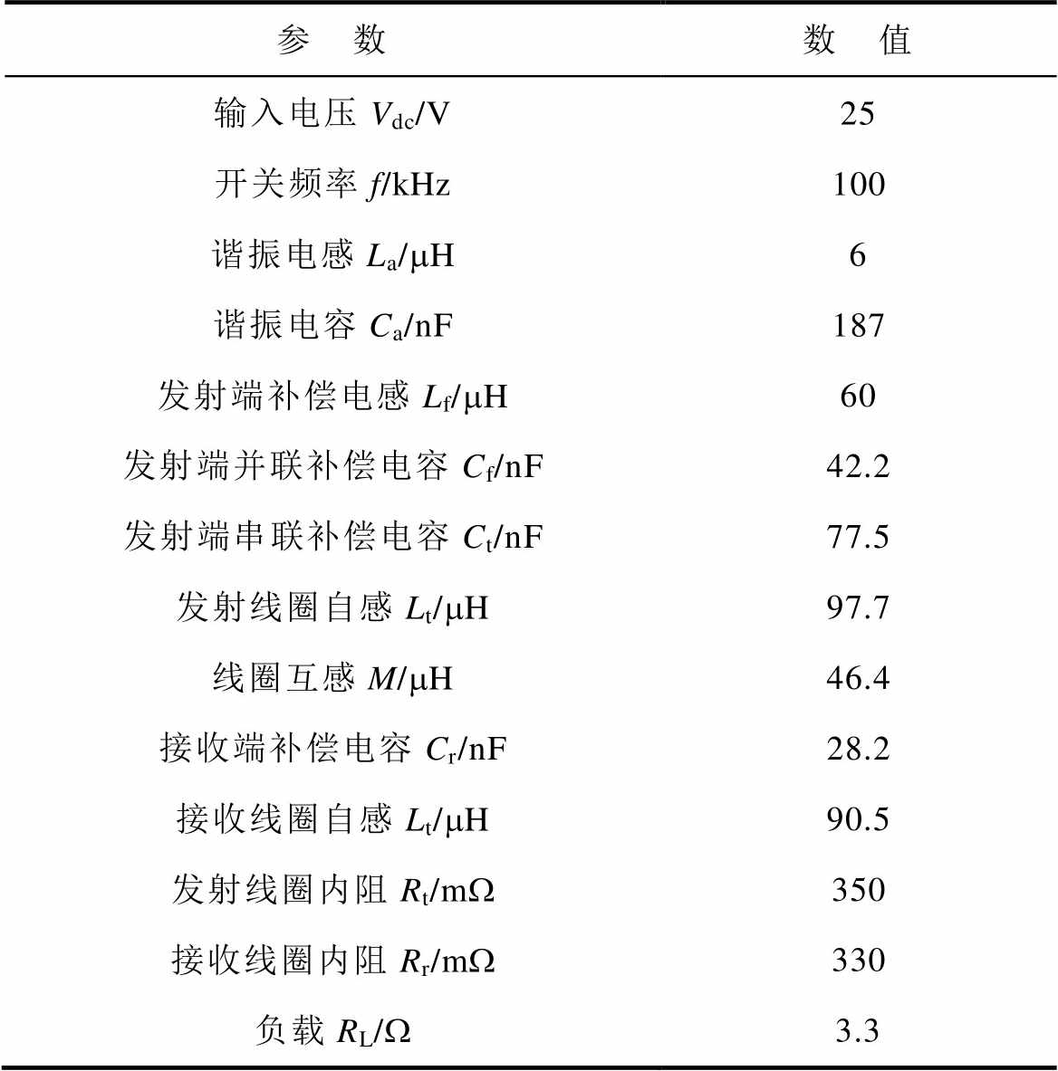
利用Matlab/Simulink软件搭建了三线圈并联发射仿真模型,参数见表1。系统开关频率为100 kHz,开关管占空比设定为0.5。
表1 单管WPT系统样机参数
Tab.1 Prototype parameters of single switch WPT system
参 数数 值 输入电压Vdc/V25 开关频率f/kHz100 谐振电感La/mH6 谐振电容Ca/nF187 发射端补偿电感Lf/mH60 发射端并联补偿电容Cf/nF42.2 发射端串联补偿电容Ct/nF77.5 发射线圈自感Lt/mH97.7 线圈互感M/mH46.4 接收端补偿电容Cr/nF28.2 接收线圈自感Lt/mH90.5 发射线圈内阻Rt/mW350 接收线圈内阻Rr/mW330 负载RL/W3.3
3.1.1 子系统均衡耦合仿真结果验证
为了验证P#型单管谐振逆变结构的优越性,将传统型和P#型LCC补偿拓扑参数设为一致。系统均衡耦合时,传统单管谐振逆变LCC补偿网络移相前后的输入电流 对比如图12所示。当子系统采用同时导通的控制策略时,输入电流畸变严重,THD为47.1 %,直流分量为7.5 A,基波有效值为7.7 A;当子系统采用依次移相120 °导通时,电流幅值大幅度降低,但电流畸变更加严重,THD为61.1 %,此时直流分量为7.4 A,基波有效值为1.9 A。
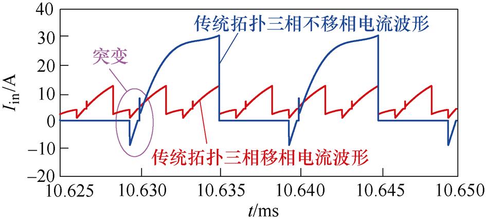
图12 传统单管谐振逆变器LCC补偿网络移相120 °前后输入电流对比
Fig.12 Comparison of input current before and after phase shifting 120 °in traditional single switch LCC topology
P#型单管谐振逆变子系统同时导通的输入电流 ,如图13所示。THD为32.8 %,直流分量为7.4 A,基波有效值为11.4 A;子系统依次移相120 °导通后电流波形平滑,THD值大幅度降低,仅为6.1 %,直流分量为7.4 A,基波有效值降至0.68 A。
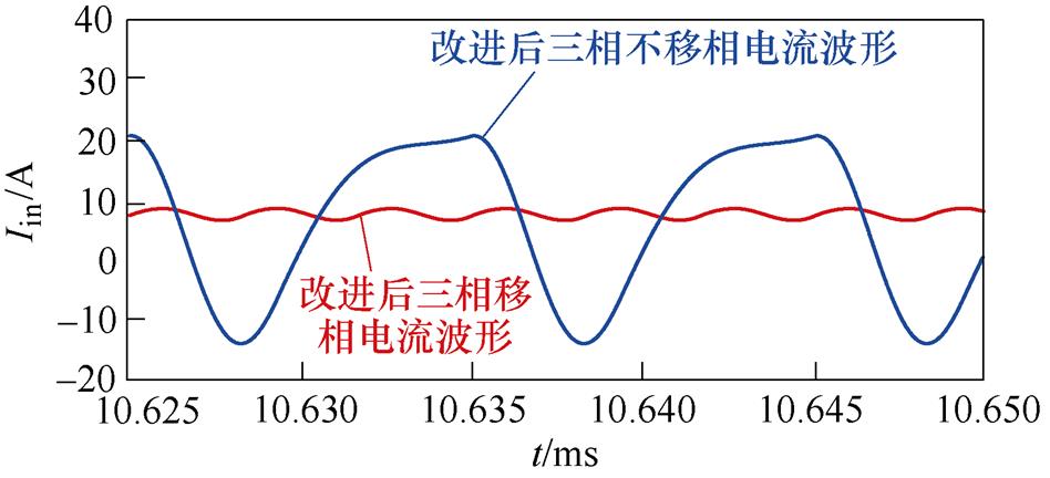
图13 P#型单管谐振逆变器LCC补偿网络移相120 °前后输入电流对比
Fig.13 Comparison of input current before and after phase shift 120 °of P# single switch LCC topology after change
3.1.2 子系统非均衡耦合仿真结果验证
为了验证所提出的移相抑制纹波方法的普适性和有效性。设置P#型单管谐振逆变子系统的耦合系数分别为M1=50 mH、M2=46.4 mH、M3=42 mH。根据式(17)求得输入电流 、
、 、
、 的最佳移相角度分别为0 °、125.7 °、239.7 °。移相前后输入电流
 对比如图14所示。所有子系统同时导通时,输入电流的THD为32.9 %,直流分量为7.4 A,基波有效值为11.2 A;移相导通后输入电流THD值大幅降低,仅为9.7 %,直流分量为7.5 A,基波有效值仅为0.66 A。
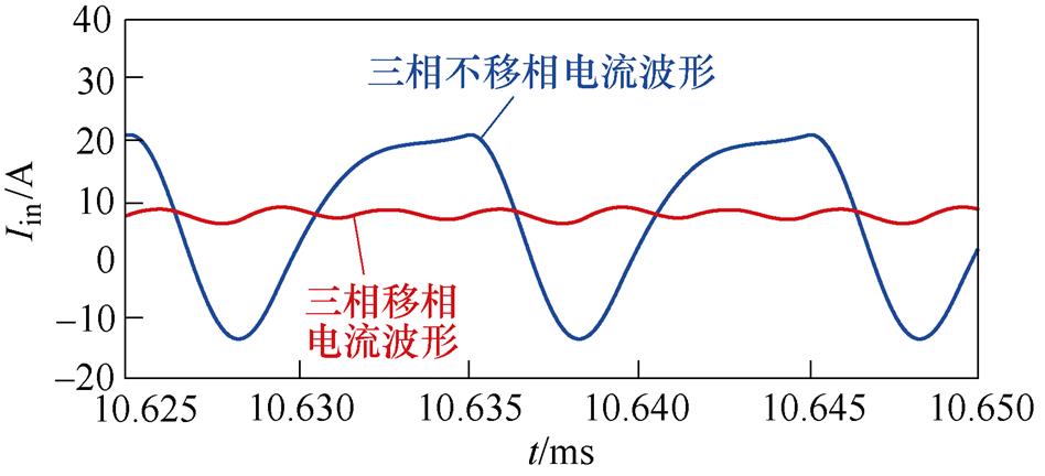
图14 耦合系数M1=50 mH、M2=46.4 mH、M3=42 mH移相前后输入电流对比
Fig.14 Comparison of input current before and after phase shift with M1=50 mH, M2=46.4 mH, M3=42 mH
为了深入验证本文所提出方法的可行性,搭建了实验平台,如图15所示。图中①~⑩分别为耦合机构、逆变器、整流器、DC-DC模块、控制系统、电压电流探头、示波器、直流电源、电子负载以及辅助电源。其中控制器采用STM32F407ZGT6,开关管选用B33N60E功率MOSFET;发射和接收线圈的匝数为24匝。
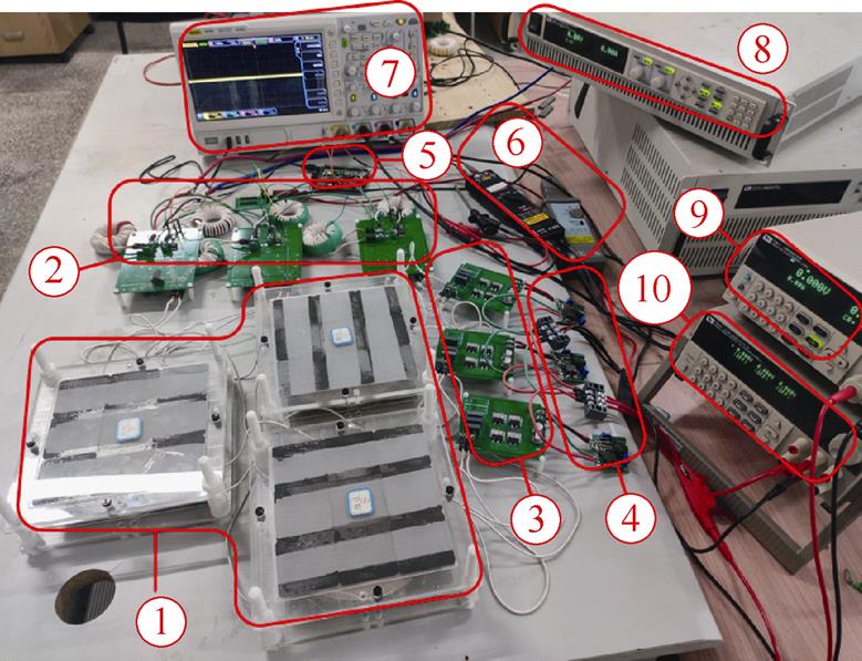
图15 实验样机
Fig.15 Experimental prototype
图16为逆变器1开关管的软开关波形。当开关管的驱动信号Vgs从t1时刻的低电平变为t2时刻的高电平之前,开关管的漏源极电压Vds已降为零,说明开关管实现了零电压开通。
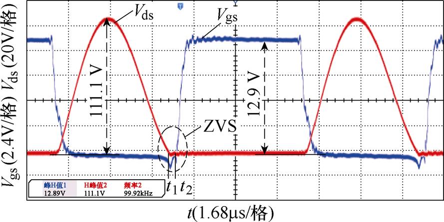
图16 MOSFET管软开关波形
Fig.16 Soft switching waveforms of MOSFET
图17为整流器1的输入电压Vo和输入电流Ir的波形,输入电压Vo的有效值为22.46 V,输入电流Ir的有效值为2.4 A。
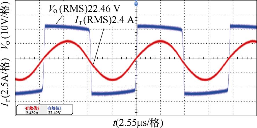
图17 整流器输入电压、电流波形
Fig.17 Input voltage and current waveforms of the rectifier
图18为传统单管谐振逆变和P#型单管谐振逆变LCC补偿拓扑的输入电流 的对比,经对比分析可知,由于电源的钳位作用,使传统单管谐振逆变器输入电流Iin畸变减小,但P#型LCC补偿拓扑输入电流更为平滑。
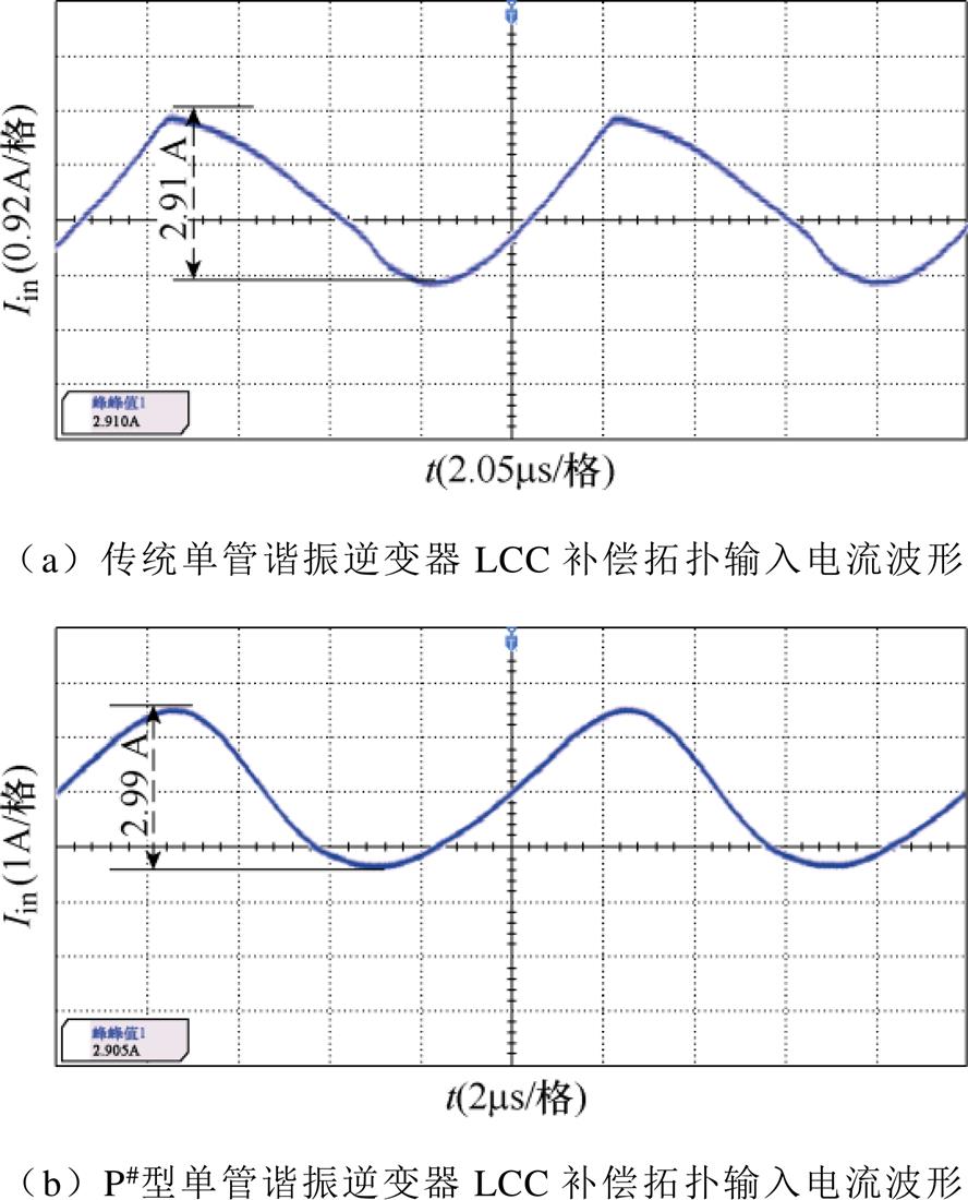
图18 两种补偿拓扑输入电流波形对比
Fig.18 Comparison of input current waveforms of two compensation topologies
图19为基于P#型单管谐振逆变子系统在传输距离均为50 mm情况下并联移相前后的输入电流波形对比,系统移相前输入电流的纹波大,其峰-峰值为8.5 A;子系统分别移相0 °、123.7 °、241.5 °后系统的输入电流峰-峰值为2.76 A,移相后大幅度降低了输入电流的纹波,输入电流波形更加稳定。
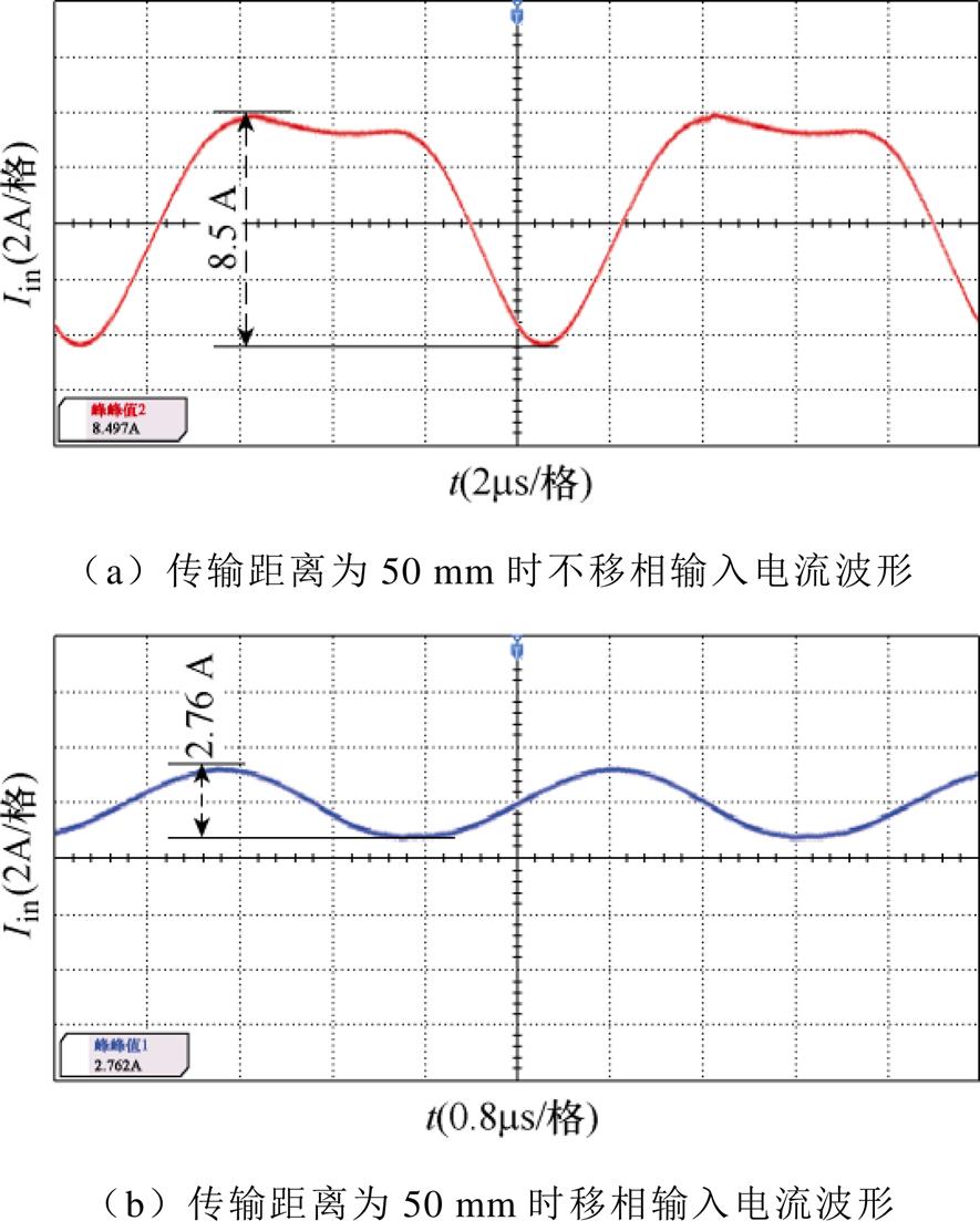
图19 传输距离为50 mm时移相前后波形对比
Fig.19 Waveforms comparison of shifted phase before and after when the transmission distance is 50 mm
图20为基于P#型单管谐振逆变子系统在传输距离分别为40 mm、50 mm和60 mm情况下并联移相前后的输入电流波形,系统移相前输入电流峰-峰值为6.98 A;子系统分别移相0 °、88.7 °、251.4 °后系统的输入电流峰-峰值为1.6 A。说明所提出的方法在系统非均衡情况下同样具有良好的抗偏移控制性能。
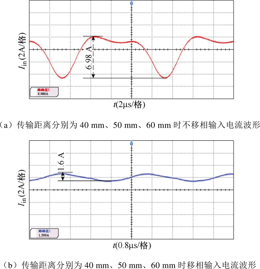
图20 传输距离为40 mm、50 mm、60 mm时移相前后波形
Fig.20 Waveforms comparison of shifted phase before and after when the transmission distance is 40 mm, 50 mm, 60 mm
图21a为正对齐时负载为4W 情况下DC-DC模块输出电压、电流波形,此时输出电压为23.26 V,输出电流分别为1.82、1.86、1.94 A。图21b分别为正对齐、偏移10、20 mm时负载为4W 情况下DC-DC模块输出的电压、电流波形,此时输出电压为23.26 V,输出电流分别为1.78、1.85、1.93 A。
图22a、图22b分别为均衡耦合与非均衡耦合在不同负载情况下输出电流对比。从而证明了在不均衡耦合下输出电流差异较小,有效抑制了环流的产生。
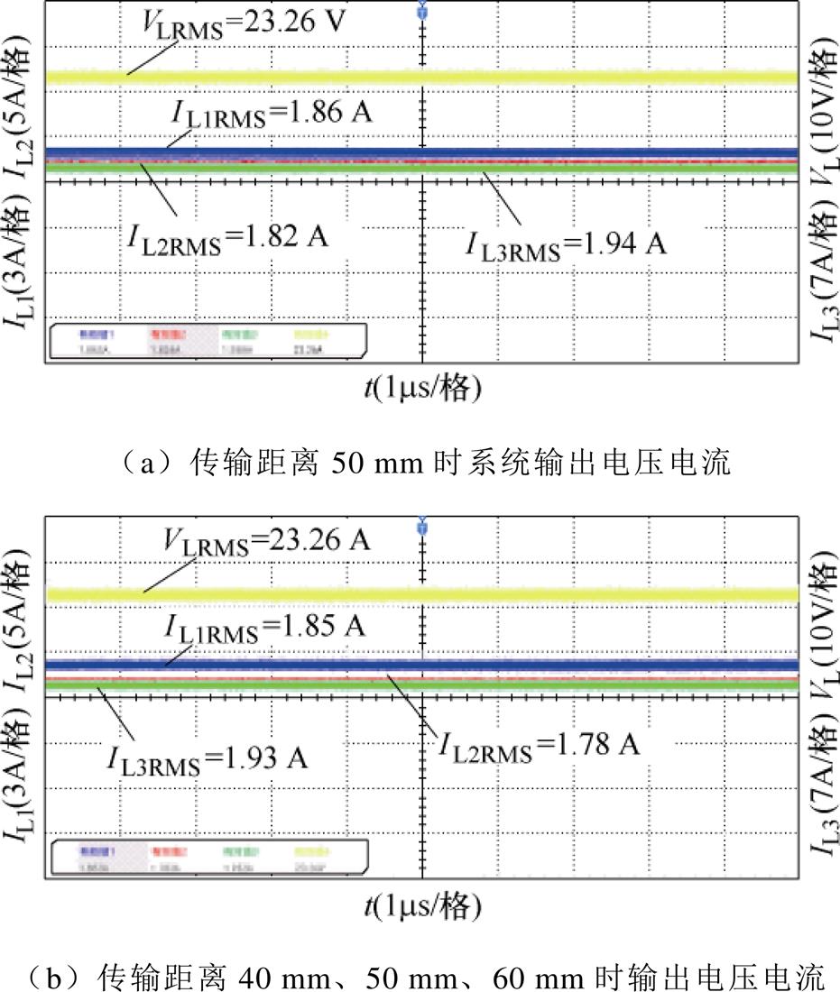
图21 不同耦合情况下输出电压电流波形
Fig.21 Output voltage current waveform in different coupling conditions
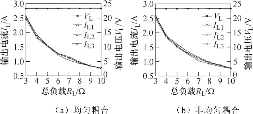
图22 输出电压电流对比
Fig.22 Output voltage current comparison
图23为单线圈传统型拓扑与P#型拓扑效率对比,随着输入电压的不断增大,当输入电压小于15 V时,传统拓扑效率远低于P#拓扑,但随着输入电压增大,二者效率差距逐渐减小,当输入电压为25 V时传统拓扑的效率为84.7 %,移相后的效率为85.9 %,提升了1.2 %。当输入电压为30 V时传统拓扑的效率为85 %,P#拓扑的效率为86.1 %。
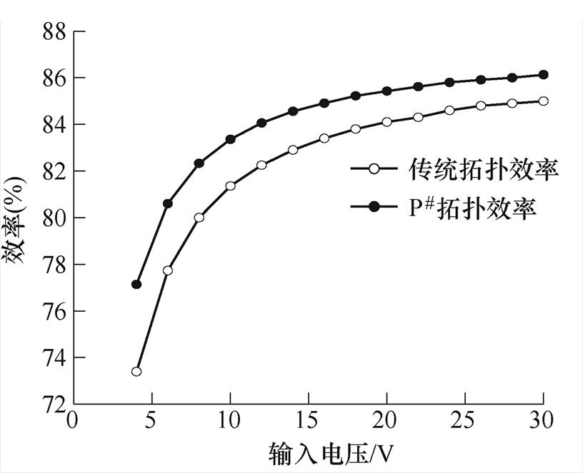
图23 两种补偿拓扑的效率对比
Fig.23 Comparison of system efficiency under two compensation topologies
图24为三线圈并联输入移相前后的效率变化,随着输入电压的不断增大,当输入电压大于8 V时,移相后效果逐渐优于不移相的效果,当输入电压为25 V时移相前的效率为83.8 %,移相后的效率为87.6 %,提升了3.8 %。当输入电压为30 V时移相前的效率为83.9 %,移相后的效率为88.2 %。其根本原因在于采用所提出的控制方法后有效改善了输入电流纹波,从而使得系统效率增加。
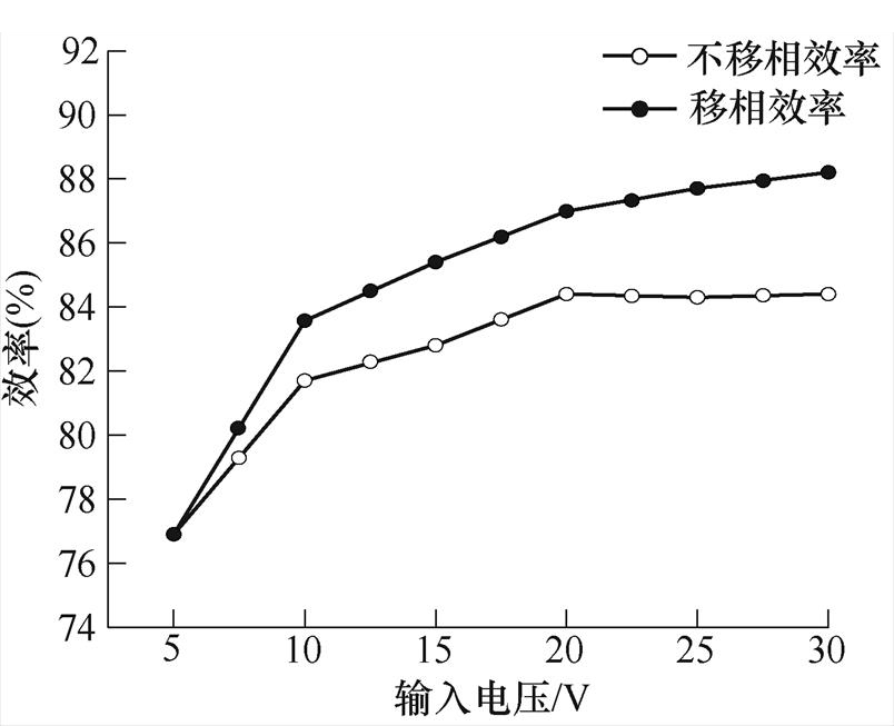
图24 移相前后传输效率对比
Fig.24 Comparison of transmission efficiency before and after phase shift
本文针对电动助力车的单管无线电能传输系统,首先提出一种新颖的P#型LCC-S补偿网络;然后利用所提方法对纹波进行移相抑制,减小系统输入电流的纹波,提高系统效率;最后进行了仿真与实验验证。证明了该方法的有效性和可行性;并得出以下关键性结论:
1)将谐振电容Ca与开关管并联可有效改善输入电流波形,减小输入电流THD值,额定输入电压的情况下系统效率从84.7 %提升至85.9 %,提升了1.2 %。
2)通过控制多线圈激励电流移相的方式,可以有效消除输入电流纹波,使得输入电流变得稳定,进而提高系统效率。
3)在输入电压为25 V、额定功率150 W情况下,系统优化前后效率从83.8 %提升至87.6 %,提升了3.8 %。
参考文献
[1] 张波, 疏许健, 黄润鸿. 感应和谐振无线电能传输技术的发展[J]. 电工技术学报, 2017, 32(18): 3-17.
Zhang Bo, Shu Xujian, Huang Runhong. The development of inductive and resonant wireless power transfer technology[J]. Transactions of China Elec- trotechnical Society, 2017, 32(18): 3-17.
[2] 吴理豪, 张波. 电动汽车静态无线充电技术研究综述(下篇)[J]. 电工技术学报, 2020, 35(8): 1662- 1678.
Wu Lihao, Zhang Bo. Overview of static wireless charging technology for electric vehicles: part Ⅱ[J]. Transactions of China Electrotechnical Society, 2020, 35(8): 1662-1678.
[3] 程时杰, 陈小良, 王军华, 等. 无线输电关键技术及其应用[J]. 电工技术学报, 2015, 30(19): 68-84.
Cheng Shijie, Chen Xiaoliang, Wang Junhua, et al. Key technologies and applications of wireless power transmission[J]. Transactions of China Electro- technical Society, 2015, 30(19): 68-84.
[4] 薛明, 杨庆新, 章鹏程, 等. 无线电能传输技术应用研究现状与关键问题[J]. 电工技术学报, 2021, 36(8): 1547-1568.
Xue Ming, Yang Qingxin, Zhang Pengcheng, et al. Application status and key issues of wireless power transmission technology[J]. Transactions of China Electrotechnical Society, 2021, 36(8): 1547-1568.
[5] Yang Yi, Zhang Xuejian, Luo Lei, et al. Research on high power factor single tube variable structure wireless power transmission[J]. World Electric Vehicle Journal, 2021, 12(4): 214.
[6] 赵争鸣, 刘方, 陈凯楠. 电动汽车无线充电技术研究综述[J]. 电工技术学报, 2016, 31(20): 30-40.
Zhao Zhengming, Liu Fang, Chen Kainan. New progress of wireless charging technology for electric vehicles[J]. Transactions of China Electrotechnical Society, 2016, 31(20): 30-40.
[7] 黄先进, 赵鹃, 游小杰. 一种基于输入串联输出并联移相全桥变换器的改进交错控制方法[J]. 电工技术学报, 2020, 35(增刊1): 81-90.
Huang Xianjin, Zhao Juan, You Xiaojie. An improved interlace control method based on input series output parallel phase-shifted full-bridge converter[J]. Transa- ctions of China Electrotechnical Society, 2020, 35(S1), 81-90.
[8] 潘超, 刘凯旭, 郑永健, 等. 计及互感参数的串联-并联型无线电能系统传输特性[J]. 电工技术学报, 2016, 31: 39-44.
Pan Chao, Liu Kaixu, Zheng Yongjian, et al. Transmission characteristics of wireless power system in series-parallel type considering mutual indu- ctance[J]. Transactions of China Electrotechnical Society, 2016, 31: 39-44.
[9] Zhu Ao, Zhou Hong, Deng Qijun, et al. Modeling and phase synchronization control of high-power wireless power transfer system supplied by modular parallel multi-inverters[J]. IEEE Transactions on Vehicular Technology, 2021, 70(7): 6450-6462.
[10] Li Yong, Hu Jiefeng, Li Xiaofei, et al. Efficiency analysis and optimization control for input-parallel output-series wireless power transfer systems[J]. IEEE Transactions on Power Electronics, 2020, 35(1): 1074-1085.
[11] Huang Ying, Lee A T L, Tan S C, et al. Highly efficient wireless power transfer system with single- switch step-up resonant inverter[J]. IEEE Journal of Emerging and Selected Topics in Power Electronics, 2021, 9(1): 1157-1168.
[12] 李厚基, 王春芳, 岳睿, 等. 基于SiC器件的单管无线电能传输电路研究[J]. 中国电机工程学报, 2020, 40(6): 1808-1817.
Li Houji, Wang Chunfang, Yue Rui, et al. Research on single-switch wireless power transfer circuit based on SiC device[J]. Proceedings of the CSEE, 2020, 40(6): 1808-1817.
[13] 赵靖英, 周思诺, 崔玉龙, 等. 磁耦合谐振串并式无线电能传输功率稳定性研究[J]. 电工电能新技术, 2018, 37(8): 20-29.
Zhao Jingying, Zhou Sinuo, Cui Yulong, et al. Research on power stability of magnetic resonance wireless power transmission with series-parallel structure[J]. Advanced Technology of Electrical Engineering and Energy, 2018, 37(8): 20-29.
[14] 葛学健, 孙跃, 唐春森, 等. 用于动态无线供电系统的双输出逆变器[J]. 电工技术学报, 2020, 35(4): 786-798.
Ge Xuejian, Sun Yue, Tang Chunsen, et al. Dual- output inverter for dynamic wireless power transfer system[J]. Transactions of China Electrotechnical Society, 2020, 35(4): 786-798.
[15] 陈国东, 吴剑青, 孙跃, 等. 基于互感差异的双拾取无线电能传输系统功率分配控制策略[J]. 电力系统自动化, 2018, 42(21): 154-159.
Chen Guodong, WuJianqing, SunYue, et al. Power distribution control strategy of wireless power transfer system with dual-pickup coils based on mutual inductance difference[J]. Automation of Elec- tric Power Systems, 2018, 42(21): 154-159.
[16] 麦瑞坤, 陆立文, 李勇. 两逆变器并联IPT系统的环流消除方法研究[J]. 电工技术学报, 2016, 31(3): 8-15.
Mai Ruikun, Lu Liwen, Li Yong. Circulating current elimination of parallel dual-inverter for IPT systems[J]. Transactions of China Electrotechnical Society, 2016, 31(3): 8-15.
[17] 尚捷, 贾建波, 戴欣, 等. 面向低压输入MC-WPT系统高增益桥式补偿网络研究[J]. 重庆大学学报, 2021, 44(7): 82-98.
Shang Jie, Jia Jianbo, Dai Xin, et al. Research on high gain bridge compensation network for low voltage input MC-WPT system[J]. Journal of Chongqing University, 2021, 44(7): 82-98.
[18] 何祥瑞, 荣灿灿, 刘明海. 基于无线电能传输系统多线圈结构参数优化设计[J]. 电工技术学报, 2021, 36(增刊2): 404-411.
He Xiangrui, Rong Cancan, Liu Minghai. Optimi- zation design of multi-coil structure parameters based on wireless power transfer system[J]. Transactions of China Electrotechnical Society, 2021, 36(S2): 404- 411.
[19] 卢伟国, 陈伟铭, 李慧荣. 多负载多线圈无线电能传输系统各路输出的恒压特性设计[J]. 电工技术学报, 2019, 34(6): 1137-1147.
Lu Weiguo, Chen Weiming, Li Huirong. Multi-load constant voltage design for multi-load and multi-coil wireless power transfer system[J]. Transactions of China Electrotechnical Society, 2019, 34(6): 1137- 1147.
[20] 刘姜涛, 邓其军. 并联多逆变器驱动的大功率无线电能传输系统研发[J]. 武汉大学学报(工学版), 2020, 53(2): 168-175.
Liu Jiangtao, Deng Qijun. Development of high power wireless power transfer system driven by multiple inverters in parallel[J]. Engineering Journal of Wuhan University, 2020, 53(2): 168-175.
[21] 罗成鑫, 丘东元, 张波, 等. 多负载无线电能传输系统[J]. 电工技术学报, 2020, 35(12): 2499-2516.
Luo Chenxin, Qiu Dongyuan, Zhang Bo, et al. Wireless power transfer system for multiple loads[J]. Transactions of China Electrotechnical Society, 2020, 35(12): 2499-2516.
[22] 李厚基, 刘明, 杨煜志, 等. 基于E类逆变电路的宽负载范围软开关无线充电补偿网络研究[J/OL]. 中国电机工程学报: 1-14[2022-10-14].
Li Houji, Liu Ming, Yang Yuzhi, et al. Research on wide load range soft switching wireless charging compensation network based on class e inverter circuit[J/OL]. Proceedings of the CSEE, 1-14 [2022-10-14].
[23] 王春芳, 岳睿, 李厚基, 等. 基于单管电路的恒流恒压无线充电系统研究[J]. 电工技术学报, 2021, 36(22): 4637-4647, 4657.
Wang Chunfang, Yue Rui, Li Houji, et al. Research on constant-current and constant-voltage wireless charging system based on single-switch circuit[J]. Transactions of China Electrotechnical Society, 2021, 36(22): 4637-4647, 4657.
[24] Roslaniec L, Jurkov A S, Bastami A A, et al. Design of single-switch inverters for variable resistance/load modulation operation[J]. IEEE Transactions on Power Electronics, 2015, 30(6): 3200-3214.
[25] 陈天牧, 曾国宏, 王静, 等. 抑制电流纹波的模块化多电平直流变换器移相调制策略[J]. 电力系统自动化, 2021, 45(21): 206-214.
Chen Tianmu, Zeng Guohong, Wang Jing, et al. Phase-shifted modulation strategy of modular multi- level DC/DC converter for current ripple supper- ssion[J]. Automation of Electric Power Systems, 2021, 45(21): 206-214.
Abstract In wireless power transfer technology, full-bridge or half-bridge topology is mainly adopted for the multi-coil parallel transmission system. However, its control and peripheral circuits are complicated, and two switches in series in the inverter turn-on simultaneously will cause a short circuit. In contrast, the single-switch resonant inverter circuit has the advantages of high reliability, simple control, low cost, and easily realizing zero-voltage turn-on. It also has the disadvantages of limited transmission power and significant input current ripple. Hence, by connecting multiple transmitters in parallel and controlling the angle of the input current of the system, the conducting current ripple is suppressed, and the transfer power is increased. It is an effective way to overcome the deficiency of the single-switch resonant inverter. Moreover, the control scheme of the system is simpler than the full-bridge topology if the transfer power is equal.
Because of the particularity of the single switch resonant inverter WPT system, the conventional LCC resonant topology can only be used indirectly. The compensation network of the single switch resonant inverter on the side of the transmitter is usually a P-type structure. The resonant frequency of the PP type and PS type is determined by the transmitter Lt, the receiver Lr, mutual inductance M and the load RL. However, when the magnetic coupler is misaligned, the mutual inductance M will be varied, which will significantly change the resonant frequency of the system. Eventually, it will affect the transmission power and efficiency of the WPT system. In addition, the voltage gain and the quality factor of the P-type compensation network are low, the DC input voltage in normal operation is high, and the filtering effect of the system on high-order harmonics is poor.
The LCC topology has the following advantages when working normally:
(1) Adjusting the compensation network parameters to make the system constant voltage output.
(2) The mutual inductance and load do not affect the resonant frequency of the system. It is just related to the self-inductance of the transmitter. Meanwhile, the system works stably and is hardly prone to detuning.
(3) As a high-order network, it has an excellent filtering effect on high-order harmonics for the nice quality factor. In addition, the voltage gain is adjustable, and the requirement of the input voltage level is low.
The proposed P-type LCC-S compensation network is suitable for the single-switch resonant inverter. It increases the transmission power of the system by adopting the approach of three-coil parallel input. In order to improve the THD of the input current of the system, firstly, this paper analyzed the working modes of different resonant circuits and parameters and the input current waveform to determine the P# LCC-S compensation network. Secondly, to reduce the ripple of the system input current, the relationship between the coil input current and the input voltage, mutual inductance, and load impedance in the case of three-coil unbalanced coupling was deduced. After analyzing the input current frequency domain, the RMS of fundamentals and each harmonic was obtained. The ripple is suppressed by vector analysis which improves the system's efficiency. The experimental results indicate that when the rated power is 150 W and the phase-shifting suppression strategy is adopted, the Vpp of the input current is reduced from 8.7 A to 2.76 A when the power transfer distance is 50 mm. In addition, the Vpp of the input current is reduced from 6.98 A to 1.6 A when the power transfer distance is 40 mm, 50 mm, and 60 mm. Among these situations, the highest efficiency is 88.2%.
keywords:Wireless power transfer, LCC-S compensation network, ripple suppression, single-switch resonant inverter
DOI: 10.19595/j.cnki.1000-6753.tces.221475
中图分类号:TM724
国家自然科学基金项目(52207004)、重庆市科学技术委员会面上项目(cstc2021jcyj-msxm2254)和重庆市教育委员会青年项目(KJQN202001144)资助。
收稿日期 2022-07-30
改稿日期 2022-09-30
杨 奕 男,1970年生,教授,硕士生导师,研究方向为无线电能传输技术、电能变换技术。E-mail: yangyi@cqut.edu.cn
郭 强 男,1984年生,副教授,硕士生导师,研究方向为功率变换器控制技术。E-mail: guoqiang@cqut.edu.cn(通信作者)
(编辑 郭丽军)