图1 电场和磁场对磁畴分布的影响
Fig.1 Effect of electric and magnetic fields on magnetic domain distribution
摘要 磁致伸缩位移传感器应用于高温环境时,磁致伸缩材料存在随温度升高而力磁性能下降的固有属性,因此迫切需要研究宽温域下传感器的输出特性。基于玻耳兹曼统计量、磁弹性耦合效应和德拜模型,建立了非等温条件下传感器输出电压模型。搭建提供可调脉冲电流和轴向偏置磁场的变温平台,选用直径0.8 mm的(Fe83Ga17)99.4B0.6和Fe82Ga13.5Al4.5波导丝,实验验证了模型的准确性。确定变温下传感器的最佳激励参数,(Fe83Ga17)99.4B0.6偏置磁场21.3 kA/m,脉冲电流24.6 A;Fe82Ga13.5Al4.5偏置磁场16.7 kA/m,脉冲电流18.8 A。在20~350℃用最佳激励参数测得(Fe83Ga17)99.4B0.6输出电压最高为577.63 mV,Fe82Ga13.5Al4.5输出电压最高为419.56 mV。采用输出幅值高的(Fe83Ga17)99.4B0.6波导丝根据其最佳激励参数设计了硬件电路和移动位置磁铁结构,制作宽温域传感器样机并在高温平台上进行测试,20℃时输出电压最高为595.32 mV,500℃时仍有254.67 mV,非线性误差为±1.3 mm。
关键词:磁致伸缩 位移传感器 Fe-Ga波导丝 宽温域 输出电压模型
磁致伸缩位移传感器利用磁致伸缩丝或带材的Wiedemann效应实现绝对式位移测量,以其测量精度高、抗干扰能力强、使用寿命长等优点,广泛应用于工业领域。特别在核反应堆的棒位探测[1]、航空航天执行器精确位置控制[2]等体积、质量受限的应用条件下,磁致伸缩位移传感器相较于目前广泛应用的线性可变差动式变压器传感器(Linear Variable Displacement Transducer, LVDT)具有质量轻、体积小和精度高的优势[3-4]。随着能源电力、航空航天等领域的发展,迫切需要能够在高温环境(300~500℃)下稳定工作的位移传感器,但磁致伸缩位移传感器工作环境温度高于室温时,存在输出电压减弱、信号衰减增大、测量精度下降等问题,限制其在高温条件下的应用[5]。
磁致伸缩位移传感器的测量原理是通过检测扭转波的飞行时间(Time of Flight, TOF),即永磁体处产生的扭转波传导至检测线圈的时间,乘以扭转波波速即为被测位移[6]。国内外学者在磁致伸缩位移传感器输出特性的理论研究方面做了大量工作。E. Hristoforou等[7-8]从能量、磁化强度的增量变化方面分析了与磁致伸缩位移传感器输出电压的关系。A. Affanni等[9]分析电流产生的激励磁场,研究脉冲电流脉宽与幅值对磁致伸缩位移传感器输出电压的影响。赵辉等[10]基于Wiedemann效应和电磁定律进一步给出了激励磁场与输出电压表达式,并提出双丝差动型结构,提高位移传感器的检测精度与抗干扰能力。Kang Yihua等[11]基于磁源波动效应解释磁致伸缩位移传感器的信号产生机理,提出铁磁屏蔽的接收线圈结构,最大输出电压可达16 mV。周新志等[12]研究了磁致伸缩、磁滞特性、周向和纵向磁场对输出的影响,明确了Wiedemann效应在波导丝中产生弹性波的机理。张露予等[13-14]根据磁机耦合原理构建室温下磁致伸缩位移传感器检测电压输出模型并实验验证,当激励磁场与偏置磁场均为3 kA/m、螺旋磁场强度为4.24 kA/m时,输出最大电压18.09 mV。王博文等[15-16]通过研究输出电压与波导丝磁致伸缩差ll-lt的线性相关性,用Wiedemann效应和逆磁致伸缩效应解释了位移传感器中扭转波和电压信号的产生,并发现Fe-Ga相比Fe-Ni波导丝输出电压提高40 mV,精度提高2倍以上。
然而,以上研究均未考虑温度对传感器输出特性的影响,实际上,温度会对磁性材料的力磁性能产生影响,改变传感器的输出特性。文献[13-15]根据位移传感器的输出电压与螺旋磁场的函数关系,通过分析有效场、应力场和磁化强度的关系,得到应力和磁场共同作用下的输出电压模型。文献[16-18]从磁畴角度分析应力对Wiedemann效应的影响,结合铁基合金的非线性模型和磁致伸缩逆效应建立磁致伸缩位移传感器的输出电压模型。但上述理论模型只适用于分析室温下传感器的输出电压,而变温下的输出特性还不明确,目前建立的输出电压模型和结构设计不适用于高温环境[19-20]。
本文拟建立非等温条件下的输出电压模型,研究变温、高温下施加在传感器上的脉冲电流、偏置磁场与输出电压强度的关系。模型可作为传感器波导丝选型和激励参数设计的依据,预测宽温域传感器的输出特性。
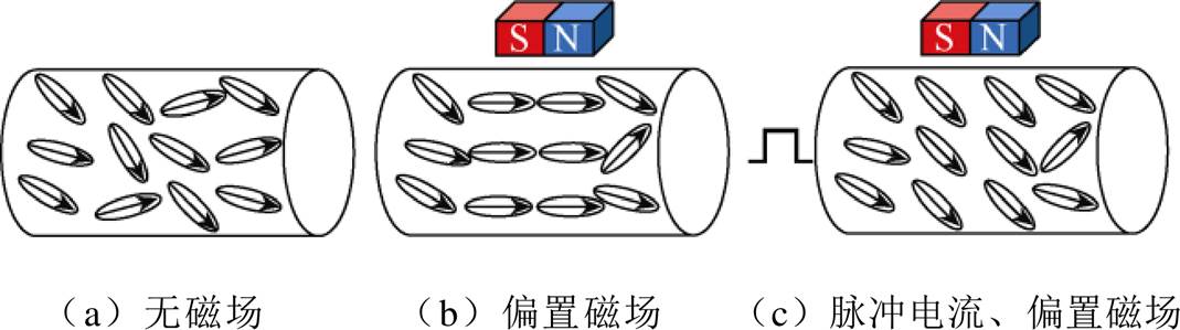
磁致伸缩波导丝所受磁场是由永磁体产生的轴向偏置磁场Hb和脉冲电流产生的环向激励磁场He合成。不同磁场条件下,波导丝内磁畴分布状态变化如图1所示。考虑到磁畴壁运动和磁畴旋转,磁致伸缩波导丝的磁化过程十分复杂。由于磁致伸缩波导丝的软磁性能非常好,因此只需考虑可逆磁化过程。
图1 电场和磁场对磁畴分布的影响
Fig.1 Effect of electric and magnetic fields on magnetic domain distribution
根据简化的玻耳兹曼统计量[21],磁矩的统计状态用非线性函数可表示为
 (1)
(1)
因此,磁化强度M可表示为
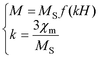 (2)
(2)
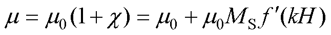
式中,k为松弛因子; 为初始线性区域磁化率;MS为饱和磁化强度;H为合成磁场强度。
在磁致伸缩波导丝中,脉冲电流持续的时间为ms级,频率高,在波导丝中的分布符合趋肤效应。考虑到畴壁运动和磁畴旋转,激励磁场He的磁化过程非常复杂,沿着磁致伸缩波导丝的环向激励磁场He不仅造成了M(H)函数的非系统和可逆部分的扭转,还导致M(H)函数的滞后和不可逆部分的巴克豪森跳跃[22]。为了简化算法,只计算磁化的可逆部分。
波导丝不同半径处的电流密度可表示为
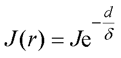 (3)
(3)
式中,d为距离波导丝表面的距离; 为趋肤深度;J为波导丝表面的电流密度,J可表示为
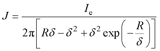 (4)
(4)
式中,Ie为脉冲电流;R为波导丝的半径。
趋肤深度可表示为
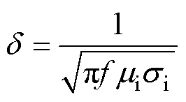 (5)
(5)
式中,f为脉冲电流的频率; 为波导丝的电导率;
 为波导丝的磁导率。
根据安培环路定理
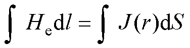 (6)
(6)
波导丝表面(距离为 )的激励磁场为
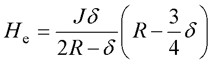 (7)
(7)
当施加脉冲电流时,波导丝在磁体位置处的磁导率 表示为
表示为
 (8)
(8)
式中, 为真空磁导率;c为磁化率,c=dM/dH,
 。
。
根据法拉第电磁感应定律,感应电动势e可表示为
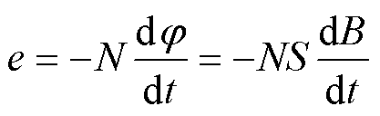 (9)
(9)
式中,N为检测线圈匝数;S为单匝线圈面积;φ为磁通量;B为磁感应强度。
根据磁机耦合方程[23],磁感应强度B与波导丝单位扭转角¶f/¶x的函数关系为
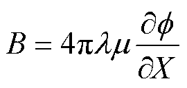 (10)
(10)
式中, 为角应变引起的磁场变化率;为波导丝的绝对磁导率。
由Wiedemann效应可知,永磁体处波导丝的扭转角与合成磁场和磁致伸缩有关[24],单位扭转角的表达式为
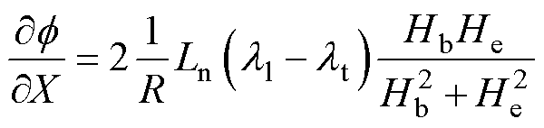 (11)
(11)
式中,Ln为检测线圈长度; 为轴向偏置磁场Hb下的轴向磁致伸缩;
 为环向激励磁场He下的横向磁致伸缩。
联立式(9)~式(11)可得合成磁场作用下磁致伸缩位移传感器的输出电压表达式为
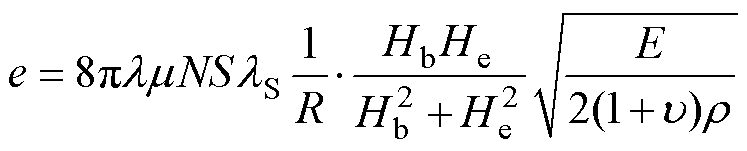 (12)
(12)
式中,lS为磁致伸缩系数;E为杨氏模量; 为泊松比;
为泊松比; 为密度。
为密度。
根据德拜模型[25]和麦克斯韦-玻耳兹曼分布推导得到杨氏模量E随温度变化的公式为
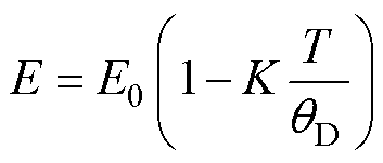 (13)
(13)
式中,E0为初始杨氏模量;T为工作温度;K= 9aqDL(c1/c),a 为热膨胀系数,qD为德拜温度。
经整理,得到非等温条件下磁致伸缩位移传感器的输出电压模型
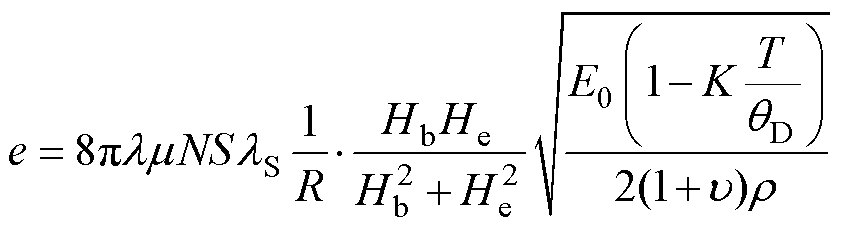 (14)
(14)
由输出模型可知,磁导率和模量较大的磁致伸缩材料有潜力获得更大的输出信号,Fe-Ga系材料在低磁场下仍有较大的磁致伸缩系数且居里温度高,可应用于高温传感器。目前,掺杂有Al和B元素后,Fe-Ga材料具有更好的塑性,易于制备成丝材。
在氩气保护下,采用高纯金属(99.9%)通过感应熔炼制备标称成分为(Fe83Ga17)99.4B0.6、Fe82Ga13.5Al4.5的铁基合金铸锭。两种铸锭分别在800℃和950℃下经过热锻和轧制加工成直径为8 mm的线材,再由冷拔和热处理等多次加工,将线材直径减小到0.8 mm。最后,用直流电源对(Fe83Ga17)99.4B0.6波导丝、Fe82Ga13.5Al4.5波导丝分别施加8.5 A和8.8 A的直流电,拉直条件下退火。通过综合物性测量系统(Physical Property Measuremnet System, PPMS)测量了两种磁致伸缩材料的磁滞回线、磁致伸缩曲线和杨氏模量-温度关系。
两种材料的磁滞回线如图2a所示,插图为在低磁场下放大的磁化回路,可见在低磁场下曲线的斜率较大,并且其斜率越大对弱磁场越敏感,更有利于本研究中的传感器应用。图2b使用标准应变仪技术测量材料的磁致伸缩系数,插图是所测试的应变片及波导丝样品,应变片附着在样品打磨光亮区域内且平行于丝轴。使用PPMS测量样品的磁致伸缩系数时,磁场的施加方向垂直于测试样品打磨的一面。从所测结果来看,两种波导丝的饱和磁致伸缩系数较高,Wiedemann效应较好。图2c是所测得的两种Fe-Ga材料在20~400℃的杨氏模量变化曲线,可以发现杨氏模量E在高温下的变化行为接近线性且有负的斜率,式(13)符合上述规律,并通过波导丝变化曲线确定L(c1/c)的值。应用于数值计算的波导丝参数见表1。磁致伸缩系数、磁化强度和杨氏模量取自测量值;磁化率和磁导率取自计算值;密度r 通过加权平均法获得;热膨胀系数a、泊松比u 取自文献[26]的实验数据。
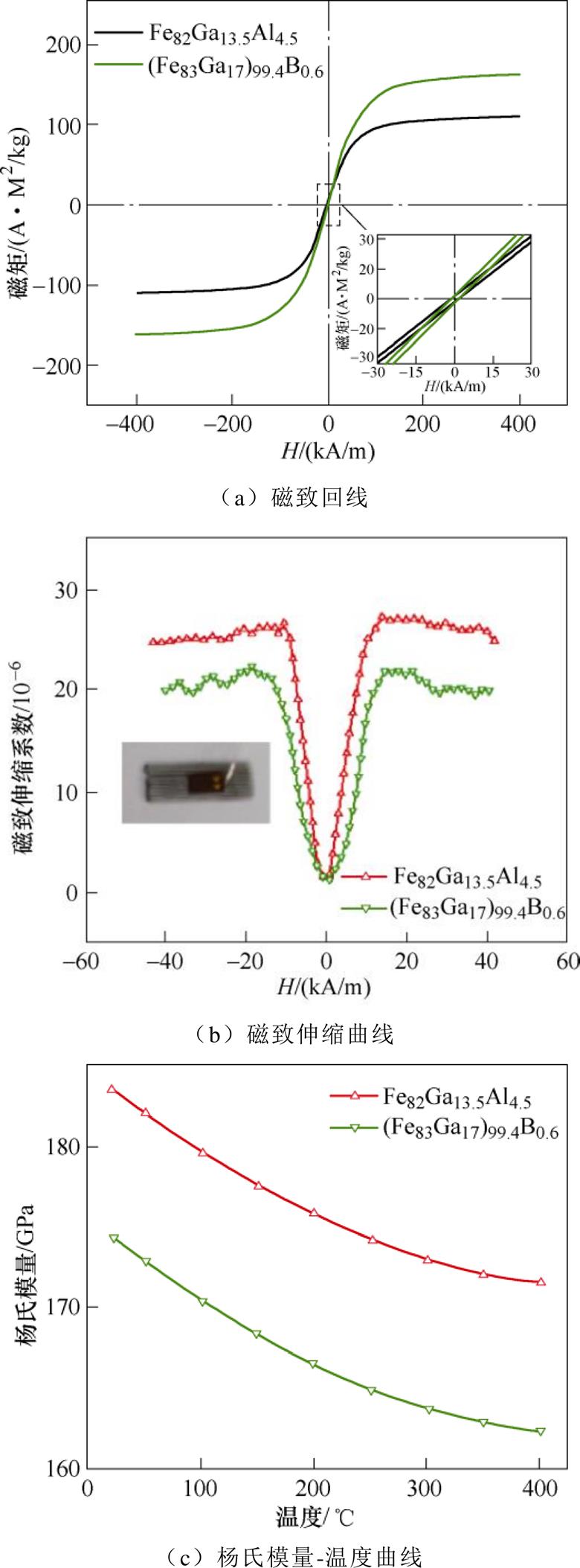
图2 Fe-Ga力磁参数测量
Fig.2 Magnetomechanical parameterof Fe-Ga
表1 波导丝参数
Tab.1 Wire parameters
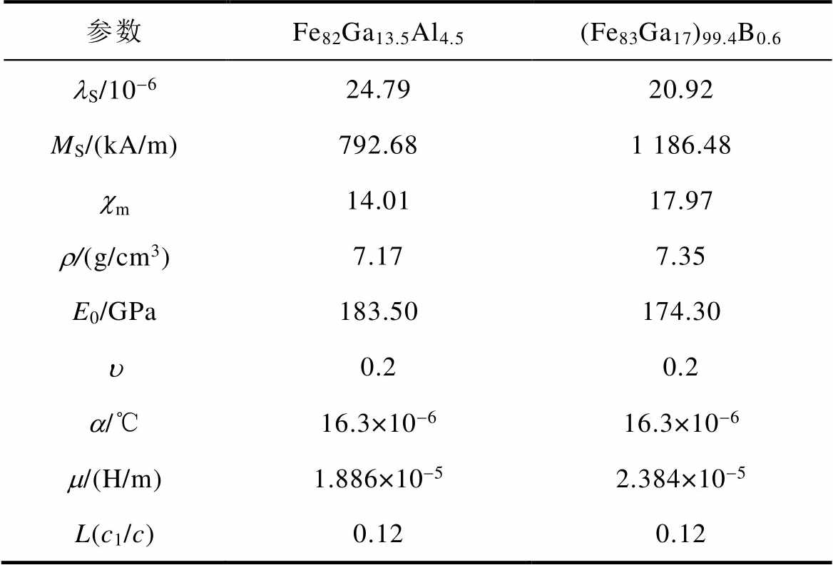
参数Fe82Ga13.5Al4.5(Fe83Ga17)99.4B0.6 lS/10-624.7920.92 MS/(kA/m)792.681 186.48 cm14.0117.97 r/(g/cm3)7.177.35 E0/GPa183.50174.30 u0.20.2 a/℃16.3×10-616.3×10-6 m/(H/m)1.886×10-52.384×10-5 L(c1/c)0.120.12
搭建了提供可调脉冲电流和轴向偏置磁场的变温测试装置如图3所示,用于研究变温下波导丝的最佳激励参数。变温测试装置由波导丝、检测线圈、永磁体、示波器、直流电源、斩波电路和高温炉组成。波导丝通过陶瓷管的中心被铜夹拉直且两端装有阻尼,用于消除反射波造成的影响。检测线圈为直径0.1 mm的铜制漆包线绕制而成,内径3 mm、外径7 mm、高6 mm、匝数为800。采用SorensenXG600-1.4可编程直流电源为斩波电路提供可调直流电。斩波电路为高带宽功率的MOSFET电路,可向波导丝提供2~40 A的脉冲电流。脉冲电流的持续时间为7 ms,周期为1 ms。通过DSOX3024T型的四通道示波器采集电压信号,示波器的通道1与线圈的两个抽头相连,用于采集输出电压波形;通道2与斩波电路输出端相连,用于控制脉冲激励电压。
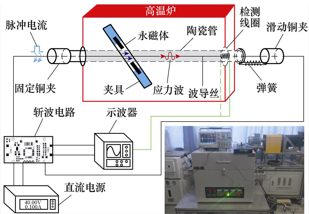
图3 变温测试装置
Fig.3 Variable temperature test platform
为了给波导丝提供不同的偏置磁场,设计了一个可以调节永磁体与陶瓷管距离的夹具。该装置分别将两块相同大小的、均沿平行于波导丝方向充磁的永磁体固定在两个基座上,把陶瓷管放在夹具中心,夹具的可调范围为5~45 mm,通过调节夹具上两个基座之间的距离,从而测量不同偏置磁场下传感器的输出电压。永磁体选用Sm2Co17,规格为长度10 mm,宽度10 mm,厚度3 mm(剩磁0.87 T,矫顽力657.39 kA/m)。使用F. W. Bell8030霍尔效应高斯计沿波导丝轴向方向测量两个永磁体中心的磁场强度,两磁体之间的距离在12.40~29.60 mm范围内调节,波导丝上的轴向偏置磁场在5~30 kA/m范围内变化。
为了得到变温下传感器最大输出电压的脉冲电流和偏置磁场,需选取较宽范围的激励参数研究。实验过程中脉冲电流施加范围为15~40 A,每次调节5 A;偏置磁场设置范围为5~30 kA/m,每次增加5 kA/m。测得25℃、150℃、250℃和350℃四个温度,(Fe83Ga17)99.4B0.6波导丝、Fe82Ga13.5Al4.5波导丝在不同Hb和Ie下实测(黑点)和计算(彩色填充面)的输出信号强度如图4所示。
从两种波导丝的输出电压随激励参数变化情况来看,实测值与计算值吻合得较好,表明式(14)可以用于预测变温下传感器的输出电压幅值,从理论分析和实验结果验证了模型的准确性。在较高的Hb和Ie下,这两个结果之间存在较大偏差,这是由于在考虑热力磁耦合特性的模型简化中忽略了磁化的不可逆和非线性过程造成的。
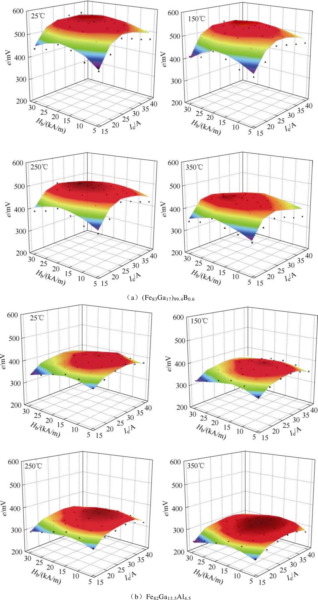
图4 不同Hb和Ie下测量的(黑点)和计算的(彩色面)输出电压
Fig.4 The measured (black dot) and calculated (color surface) output voltage under different Hb and Ie
由图4可知,(Fe83Ga17)99.4B0.6波导丝的输出电压幅值较高,输出特性较好,但两组波导丝的输出电压幅值随着温度升高都呈下降趋势。因为温度升高,波导丝的磁化强度下降,导致磁化率和磁导率下降;同时波导丝的磁致伸缩系数、杨氏模量也会随着温度升高而减小。因此,在以上材料参数变化的影响下,导致输出电压幅值下降。
根据式(14)可知,合成磁场项可转化成三角函数式为
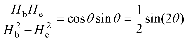 (15)
(15)
式中,合成磁场与轴向夹角θ=45°,即激励磁场强度与偏置磁场强度相等时,式(15)取最大值。通过输出电压模型计算出两种波导丝的最佳激励参数:①(Fe83Ga17)99.4B0.6波导丝偏置磁场和激励磁场为21.307 kA/m,脉冲电流为24.576 A;②Fe82Ga13.5Al4.5波导丝偏置磁场和激励磁场为16.735 kA/m,脉冲电流为18.836 A。
按计算所得的最佳激励参数实验,(Fe83Ga17)99.4B0.6波导丝的偏置磁场设置为21.3 kA/m,脉冲电流施加24.6 A;Fe82Ga13.5Al4.5波导丝的偏置磁场设置为16.7 kA/m,脉冲电流施加18.8 A。在搭建的变温测试装置进行实验,测得20~350℃的输出电压幅值如图5所示。两种波导丝的最高输出电压在230℃之前实验数据(符号)与计算结果(实线)基本一致,实验值与计算值拟合较好;但在230℃以后,实测结果与计算结果存在较大误差,这与200℃以上永磁体的磁性衰减有关。
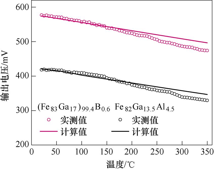
图5 20~350℃范围内测量(圆圈符号)和计算(实线)的输出电压
Fig.5 Measured (circled) and calculated (solid line) output voltage at 20~350℃
对于Fe82Ga13.5Al4.5波导丝,25℃时输出电压幅值最高,可达419.56 mV,350℃时,输出电压为329.42 mV;(Fe83Ga17)99.4B0.6波导丝,20℃时输出电压幅值最高,可达577.63 mV,350℃时输出电压为472.48 mV。从实验结果可知,(Fe83Ga17)99.4B0.6波导丝的输出电压幅值比Fe82Ga13.5Al4.5波导丝提高了150 mV,磁致伸缩效应显著。
根据(Fe83Ga17)99.4B0.6波导丝在变温下较大的输出信号,设计位移传感器样机验证高温输出性能。传感器硬件电路如图6所示,主要包括信号发生模块和信号处理模块。由Boost电路升压至70 V,然后通过高带宽功率MOSFET斩波为24.6 A、脉宽为10 ms、周期为10 ms的脉冲电流,加载到波导丝两端满足(Fe83Ga17)99.4B0.6最佳脉冲电流。MOSFET驱动信号为高电平作为开始事件,检测线圈两端信号经过滤波和放大后,与触发电压(防止杂波干扰造成非移动位置磁铁的误触发)比较作为停止事件。通过TDC测量两事件的时间差,从而得到扭转波的飞行时间(TOF)。MCU发出Boost电路和MOSFET的驱动信号,并将接收的TOF时间计算位移通过串口发出。基于最佳脉冲电流设计的硬件电路可以实现扭转波飞行时间的精确测量,提高传感器的测量精度。
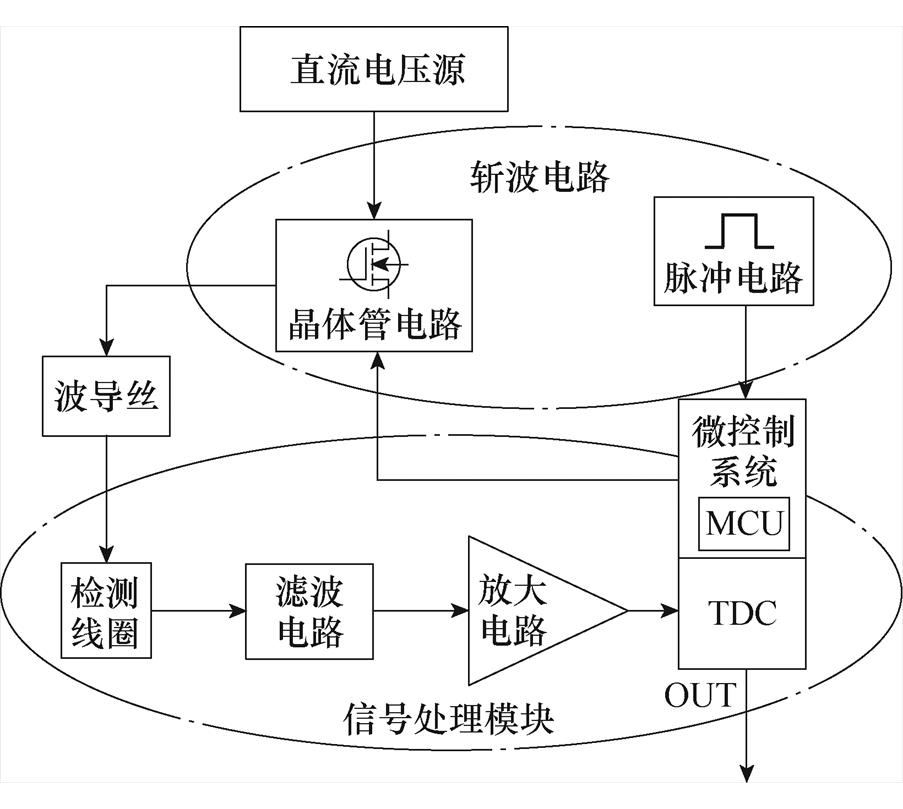
图6 电路组成示意图
Fig.6 Circuit composition schematic
传感器测量杆长度为2 400 mm,有效测量范围为0~2 200 mm,内部放置(Fe83Ga17)99.4B0.6波导丝,外部为保护套管,起到电磁屏蔽的作用。测量杆外侧设置移动位置磁铁,其内部永磁体材质为Sm2Co17,尺寸为高8 mm、直径3 mm的圆柱体,按最佳偏置磁场设计永磁体与波导丝之间的距离为d。使用Ansys Electronics Desktop软件构建传感器移动位置磁铁,结构如图7a所示,其中永磁体轴向充磁,平行放置在波导丝上下两侧;磁轭材质为电工纯铁,形状为弯曲半径为d的圆柱体极靴。参数化扫描距离d与波导丝中心位置磁场强度的关系如图7b,磁场强度随着距离d的增加呈指数下降。按照(Fe83Ga17)99.4B0.6波导丝的最佳偏置磁场确定距离d为16.7 mm。图7c显示移动位置磁铁周围磁场分布,偏置磁场方向与波导丝轴向方向一致,磁轭极靴使磁力线束更好的集中在波导丝上,提高传感器输出特性。
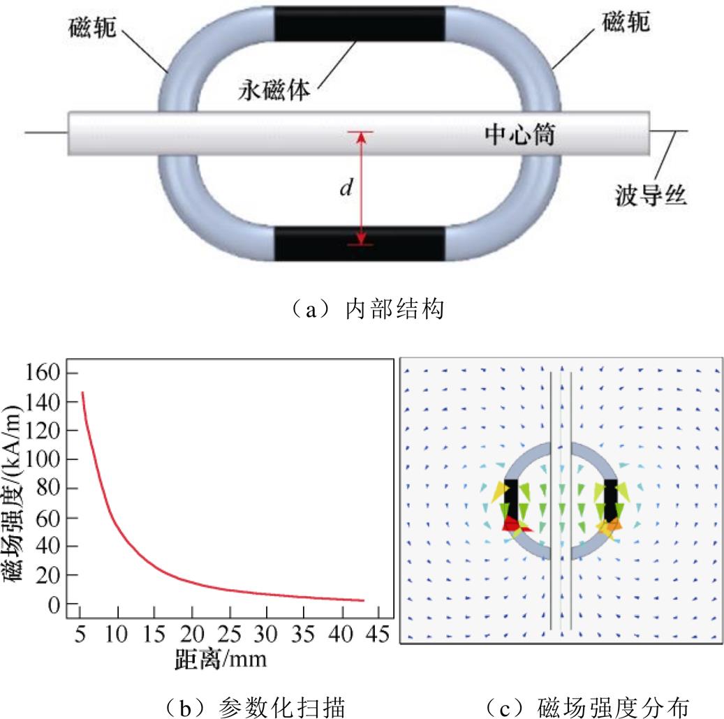
图7 移动位置磁铁结构设计
Fig.7 Structure design of mobile position magnet
为测试磁致伸缩位移传感器样机高温输出,搭建高温输出测试实验平台如图8a所示。陶瓷棒炉外一端与光栅尺读数头相连,炉内一端固定在位移传感器的移动位置磁铁上,从而实现位移传感器和光栅尺的联动测量。移动位置磁铁、陶瓷棒和测量杆1 400~2 200 mm的部分在高温炉内工作。计算机与位移传感器串口相连输出位移量,示波器用来记录传感器在高温下线圈两端的输出电压波形。为了消除扭转波的声速随温度升高而降低的影响,采用无阻尼扭转波干涉的位移测量方法[27],即通过取出波导丝两端的阻尼,使扭转波发生无阻尼反射,并调整脉冲电流的频率,实现扭转波与反射波发生干涉。在20~500℃下测量的传感器输出电压波形如图8b所示。实验结果表明:20℃时输出电压最高,可达595.32 mV,当温度升至500℃时,输出电压仍有254.67 mV。输出电压不经放大就能达到较高幅值,说明传感器输出特性较好。
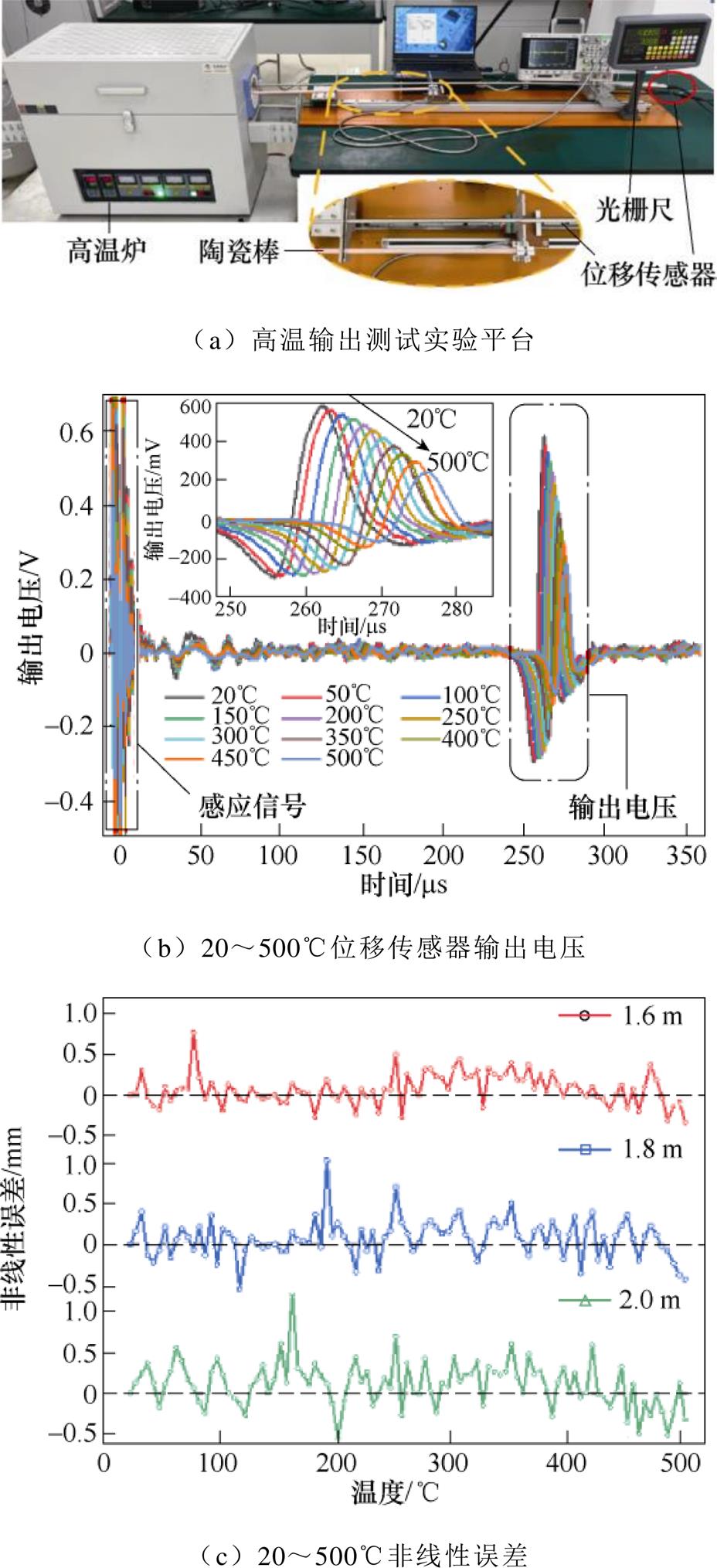
图8 测试平台及样机输出特性
Fig.8 Test platform and output characteristics of prototype
除了获得较高的输出幅值外,设计传感器时还需要考虑噪声对扭转波检测的影响[28-29]。信噪比(Signal to Noise Ratio, SNR)用于评估扭转波的有效性,公式表示为SNR=20lg(P/Q)。其中,P和Q分别代表一个触发周期内有效信号强度和噪声信号强度,噪声信号为激励脉冲电压和检测电压之间的最大电压。噪声信号过大会导致错误的信号被检测,因此在高温下工作的传感器需要较高的信噪比。通过设置合适的触发电压,可以得到检测电压和时间的坐标如图8b所示。经计算得到,20℃时传感器信噪比为13.74 dB,500℃信噪比为6.11 dB,满足高温传感器的设计要求。
通过光栅尺在零点和满量程标定后,在位移传感器测量杆的1.6 m、1.8 m和2.0 m三个测量点,测量传感器随温度变化的非线性误差。如图8c所示,位移传感器在20~500℃范围内由温升造成的测量误差为±1.3 mm,在最大允许误差范围内。从图8中可知,随着测量点位置的增加,测量误差逐渐变大,这与移动位置磁铁和检测线圈之间的距离有关。当移动位置磁铁距离检测线圈越远,扭转波的反射时间就越长,衰减情况越明显,输出电压的峰值变小,造成测量误差增大;同样,随着温度的升高导致传感器输出信号减弱,测量误差也会增大。
本文为拓展磁致伸缩位移传感器在高温、变温下的应用范围,通过提高传感器的输出电压消除温度升高引起的信号减弱和噪声干扰等不利影响,研究宽温域磁致伸缩位移传感器的输出特性。基于玻耳兹曼统计量、磁弹性耦合效应和德拜模型建立了非等温条件下磁致伸缩位移传感器输出电压模型。理论模型表明:随着温度的升高,磁致伸缩材料的磁化强度和杨氏模量降低,力磁耦合特性发生改变,传感器输出电压下降。故选用居里温度高、磁弹性能好的Fe-Ga波导丝,从实验和理论上得到了变温下传感器的最佳激励参数。研究表明:在不同温度下,当激励磁场与偏置磁场相等或接近时,可获得最大输出幅值。
基于建立的模型,确定波导丝的材料和最佳激励参数,制作磁致伸缩位移传感器样机。通过高温实验证明了制作的传感器工作温度范围宽、输出特性好、信噪比高、测量误差小,可以应用到高温、变温环境监测位置信息。研究结果可为工作在宽温域的磁致伸缩位移传感器设计优化提供理论指导。
参考文献
[1] Hu Guang, Zhang Huang, Liu Qianfeng. Review on sensors to measure control rod position for nuclear reactor[J]. Annals of Nuclear Energy, 2020, 144: 107485.
[2] Ji Yaohui, Tan Qiulin, Wang Haixing, et al. A novel surface LC wireless passive temperature sensor applied in ultra-high temperature measurement[J]. IEEE Sensors Journal, 2019, 19(1): 105-112.
[3] Yasoveev V K, Shmelev A A. Implementation methods of self-calibration in intelligent magnetostrictive transformers of linear displacements[C]//2017 2nd International Ural Conference on Measurements (UralCon), Chelyabinsk, Russia, 2017: 39-46.
[4] Zhang Shuo, Geng Tao, Wang Shengjia, et al. High- sensitivity strain and temperature simultaneous mea- surement sensor based on multimode fiber chirped long-period grating[J]. IEEE Sensors Journal, 2020, 20(24): 14843-14849.
[5] Salach J, Charubin T, Nowak P, et al. Influence of temperature on magnetostrictive delay line pro- perties[J]. Acta Physica Polonica A, 2017, 131(4): 1183-1185.
[6] Periyannan S, Balasubramaniam K. Simultaneous moduli measurement of elastic materials at elevated temperatures using an ultrasonic waveguide method[J]. Review of Scientific Instruments, 2015, 86(11): 114903.
[7] Hristoforou E, Hauser H, Ktena A. Modeling of magnetostriction in amorphous delay lines[J]. Journal of Applied Physics, 2003, 93(10): 8633-8635.
[8] Hristoforou E. New position sensor based on the magnetostrictive delay line principle[J]. Sensor Letters, 2009, 7(3): 303-309.
[9] Affanni A, Guerra A, Dallagiovanna L, et al. Design and characterization of magnetostrictive linear dis- placement sensors[C]//Proceedings of the 21st IEEE Instrumentation and Measurement Technology Con- ference (IEEE Cat. No.04CH37510), Como, Italy, 2004: 206-209.
[10] Zhang Yongjie, Liu Weiwen, Zhang Haibo, et al. Design and analysis of a differential waveguide structure to improve magnetostrictive linear position sensors[J]. Sensors (Basel, Switzerland), 2011, 11(5): 5508-5519.
[11] Deng Chao, Kang Yihua, Li Erlong, et al. A new model of the signal generation mechanism on magnetostrictive position sensor[J]. Measurement, 2014, 47: 591-597.
[12] Zhou Xinzhi, Yu Chao, Tang Zhenyu, et al. Wiede- mann effect in Fe83Ga17 alloys for magnetostrictive sensors[J]. IEEE Sensors Journal, 2014, 14(1): 249- 257.
[13] Zhang Luyu, Wang Bowen, Yin Xiaowen, et al. The output characteristics of galfenol magnetostrictive displacement sensor under the helical magnetic field and stress[J]. IEEE Transactions on Magnetics, 2016, 52(7): 1-4.
[14] 张露予, 王博文, 翁玲, 等. 螺旋磁场作用下磁致伸缩位移传感器的输出电压模型及实验[J]. 电工技术学报, 2015, 30(12): 21-26.
Zhang Luyu, Wang Bowen, Weng Ling, et al. The output voltage model of magnetostrictive dis- placement sensor in helical magnetic fields and its experimental study[J]. Transactions of China Elec- trotechnical Society, 2015, 30(12): 21-26.
[15] 王博文, 张露予, 王鹏, 等. 磁致伸缩位移传感器检测信号分析[J]. 光学精密工程, 2016, 24(2): 358-364
Wang Bowen, Zhang Luyu, Wang Peng, et al. Analysis of detection signal for magnetostrictive displacement sensor[J]. Optics and Precision Engin- eering, 2016, 24(2): 358-364.
[16] Wang Bowen, Li Yuanyuan, Xie Xinliang, et al. The output voltage model and experiment of magneto- strictive displacement sensor based on Weidemann effect[J]. AIP Advances, 2018, 8(5): 056611.
[17] 李媛媛, 王博文, 黄文美, 等. 考虑应力波衰减特性的磁致伸缩位移传感器的输出特性与实验[J]. 仪器仪表学报, 2018, 39(7): 34-41.
Li Yuanyuan, Wang Bowen, Huang Wenmei, et al. Output characteristics and experiments of magneto- strictive displacement sensor considering the attenuation characteristic of stress wave[J]. Chinese Journal of Scientific Instrument, 2018, 39(7): 34-41.
[18] 李梦星, 张艳丽, 姜伟, 等. 机械应力下电工钢片磁滞与磁致伸缩回环滞后特性模拟[J]. 电工技术学报, 2022, 37(11): 2698-2706.
Li Mengxing, Zhang Yanli, Jiang Wei, et al. Simulation of hysteresis and magnetostrictive loop hysteretic characteristics of electrical steel sheets under mechanical stress[J]. Transactions of China Electrotechnical Society, 2022, 37(11): 2698-2706.
[19] 张智贺, 杨鑫, 陈钰凯. 稀土超磁致伸缩换能器等效热网络建模研究[J]. 电工技术学报, 2022, 37(14): 3464-3474, 3565.
Zhang Zhihe, Yang Xin, Chen Yukai. Research on equivalent thermal network modeling for rare-earth giant magnetostrictive transducer[J]. Transactions of China Electrotechnical Society, 2022, 37(14): 3464- 3474, 3565.
[20] 黄文美, 夏志玉, 郭萍萍, 等. 变温条件下TbDyFe合金高频磁特性和损耗特性分析[J]. 电工技术学报, 2022, 37(1): 133-140.
Huang Wenmei, Xia Zhiyu, Guo Pingping, et al. Analysis of high frequency magnetic properties and loss characteristics of TbDyFe alloy under variable temperature[J]. Transactions of China Electro- technical Society, 2022, 37(1): 133-140.
[21] Zheng X J, Liu X E. A nonlinear constitutive model for Terfenol-D rods[J]. Journal of Applied Physics, 2005, 97(5): 053901.
[22] Lee E W. Magnetostriction and magnetomechanical effects[J]. Reports on Progress in Physics, 1955, 18(1): 184-229.
[23] 谢新良, 王博文, 周露露, 等. 磁致伸缩位移传感器波导丝扭转超声波衰减特性研究[J]. 电工技术学报, 2018, 33(3): 689-696.
Xie Xinliang, Wang Bowen, Zhou Lulu, et al. Research on torsional ultrasonic attenuation characteri- stics of the magnetostrictive displacement sensor waveguide[J]. Transactions of China Electrotechnical Society, 2018, 33(3): 689-696.
[24] 李媛媛, 王博文, 黄文美, 等. 扭转力作用下Fe-Ga磁致伸缩位移传感器的输出特性[J]. 电工技术学报, 2019, 34(21): 4409-4418.
Li Yuanyuan, Wang Bowen, Huang Wenmei, et al. Output characteristics of Fe-Ga magnetostrictive dis- placement sensor under torsional stress[J]. Transa- ctions of China Electrotechnical Society, 2019, 34(21): 4409-4418.
[25] Lakkad S C. Temperature dependence of the elastic constants[J]. Journal of Applied Physics, 1971, 42(11): 4277-4281.
[26] Li Jiheng, Li Mingming, Mu Xing, et al. Temperature and magnetic field dependencies of the Young’s modulus in magnetostrictive Fe-Ga alloys[J]. Journal of Applied Physics, 2018, 123(7): 075102.
[27] 李劲松, 梁振宗, 孙英伦, 等. 闭合Fe-Si结构中磁致伸缩引起的机械共振研究[J]. 电工技术学报, 2022, 37(6): 1321-1328.
Li Jinsong, Liang Zhenzong, Sun Yinglun, et al. Study of mechanical resonance induced by mag- netostriction in closed structures based on Fe-Si[J]. Transactions of China Electrotechnical Society, 2022, 37(6): 1321-1328.
[28] 刘美, 纽春萍, 姬忠校, 等. 基于变分模态分解的光纤电流传感器小波去噪方法[J]. 电气技术, 2021, 22(4):7-11.
Liu Mei, Niu Chunping, Ji Zhongxiao, et al. Wavelet de-noising method of all-fiber optical current transformer based on variational mode decom- position[J]. Electrical Engineering, 2021, 22(4): 7-11.
[29] 钟思翀, 祝丽花, 王前超, 等. 电力变压器振动噪声分析及其有源降噪[J]. 电工技术学报, 2022, 37(增刊1): 11-21.
Zhong Sichong, Zhu Lihua, Wang Qianchao, et al. Electromagnetic vibration of power transformer and active noise reduction[J]. Transactions of China Electrotechnical Society, 2022, 37(S1): 11-21.
Abstract Magnetostrictive displacement sensor uses the Wiedemann effect of magnetostrictive wire or strip to realize absolute displacement measurement, which has the advantages of high measurement accuracy, strong anti-interference ability, and long service life. With the technological development of energy, electric power, aerospace, and other fields, displacement sensors that can work stably at high temperatures have become urgent. However, when the working environment temperature is higher than theindoortemperature, magnetostrictive displacement sensors will face problems such as weakened output voltage, increased signal attenuation, and decreased measurement accuracy, which limit their high-temperature applications.
To expand the application range of magnetostrictive displacement sensors at high variable temperatures, this paper studies the output characteristics of magnetostrictive displacement sensors in wideoperating temperatures by increasing the output voltage of the sensor to eliminate the adverse effects of signal weakening and noise interference caused by temperature rise. In this work, Fe82Ga13.5Al4.5 and (Fe83Ga17)99.4B0.6 magnetostrictive wireswere successfully prepared, and all of their Curie temperatures are above 500℃, which could increase the upperworking temperature limit of sensors. The output voltage model of the sensor under non-isothermal conditions was established based on Boltzmann statistics, the magneto-elastic coupling effect, and the Debye model. The theoretical model shows that with the increase in temperature, the magnetization and Young's modulus of magnetostrictive material decrease. Meanwhile, the force-magnetic coupling characteristics change, and the output voltage of the sensor decreases. A temperature-variable platform with adjustable pulse current and axial bias magnetic field was setupby (Fe83Ga17)99.4B0.6 and Fe82Ga13.5Al4.5 wires with a diameter of 0.8mm. The optimal parameters of excitation pulse current and bias magnetic field of the two kinds of wires are (1) (Fe83Ga17)99.4B0.6 at 21.3 kA/m and 24.6 A; (2) Fe82Ga13.5Al4.5 at 16.7 kA/m and 18.8 A. At 20~350℃, the maximum output voltage of (Fe83Ga17)99.4B0.6 is 577.63mV, and the maximum output voltage of Fe82Ga13.5Al4.5 is 419.56 mV. The results show that the maximum output amplitude can be obtained when the excitation magnetic field equalsthe bias magnetic field at different temperatures. According to the optimal excitation parameters of (Fe83Ga17)99.4B0.6 waveguide wire, the hardware circuit and the structure of the moving position magnet are designed. A wideoperating temperature prototype was made and tested on a high-temperature platform. At 20℃, the maximum output voltage was 595.32 mV, and the SNR was 13.74 dB. At 500℃, the output voltage is 254.67 mV, and the signal-to-noise ratio is 6.11 dB. The nonlinearity error of the sensor with increasing temperature is ±1.3 mm.
The experimental results show that the magnetostrictive displacement sensor has a wide operating temperature range, good output characteristics, a high signal-to-noise ratio, and a small measurement error. Consequently, the sensors can be applied to monitor position information in high-orvariable-temperature environments. The results can provide theoretical guidance for optimizing magnetostrictive displacement sensors working in wide operating temperatures.
keywords:Magnetostriction, displacement sensor, Fe-Ga waveguide wire, wideoperating temperature, output voltage model
DOI: 10.19595/j.cnki.1000-6753.tces.221588
中图分类号:TP212
国家自然科学基金(51777053, 51801053, 52077052)、中央引导地方科技发展资金(226Z1704G)和河北省自然科学基金(E2019202315, E2022202067)资助项目。
收稿日期 2022-08-18
改稿日期 2022-09-28
李海毅 男,1998年生,硕士研究生,研究方向为新型磁性材料与器件。E-mail: hy02192022@163.com
李明明 男,1986年生,副教授,博士生导师,研究方向为新型磁性材料与器件。E-mail: Limm@hebut.edu.cn(通信作者)
(编辑 郭丽军)