 (1)
(1)
摘要 为了使电磁干扰(EMI)滤波器设计达到预期的插入损耗(IL),实现良好噪声抑制效果,需要考虑噪声源阻抗的影响。电压插入损耗法仅能获得噪声源阻抗幅值的范围,且无法求解相位。针对上述问题,在不增加实验设备的前提下,提出基于插入无源二端口网络的噪声源阻抗提取方法。该方法通过在被测设备(EUT)与线性阻抗稳定网络(LISN)之间插入3个不同的无源二端口网络,建立关于噪声源阻抗实部和虚部的二元二次方程组,再结合EMI测试频段范围内实验测量的有效频点噪声电流,以实现噪声源阻抗幅值和相位的精确计算。以一台工业照明LED驱动电源为测试对象,对该方法的有效性和适用性进行了验证。实验结果表明,相较于电压插入损耗法,所提方法能够准确地提取全频段(9kHz~30MHz)噪声源阻抗幅值的精确值,并且能够得到噪声源阻抗相位,从而可以预测EMI噪声电流,为设计性能优良的EMI滤波器提供精确理论基础。
关键词:电磁干扰 噪声源阻抗 插入损耗 EMI滤波器
电力电子功率变换器具有效率高、体积小等优点,在许多领域得到广泛应用[1-3]。但由于电力电子功率变换器的功率开关器件在开关过程中会产生很高的dv/dt、di/dt,通过电路的寄生电感和寄生电容形成严重的电磁干扰(Electromagnetic Interference, EMI)问题,特别是随着开关频率、开关速度更快的宽禁带开关器件SiC、GaN的应用,变换器功率密度进一步提升,EMI问题亟待解决[4-7]。为了达到预期噪声抑制效果,必须设计性能优越的EMI滤波器。EMI滤波器的性能由插入损耗(Insertion Loss, IL)来表征,其中噪声源阻抗对插入损耗的影响不可忽视。EMI滤波器的设计流程可以概括为:首先根据阻抗失配原则进行拓扑选择;其次综合考虑噪声源阻抗和负载阻抗的精确数据计算滤波器的理论插入损耗;再次令其等于功率变换器所需实现的插入损耗;最后实现滤波器的设计和选型[8-9]。因此,在设计EMI滤波器之前,对噪声源阻抗进行分析和提取具有重要意义。
噪声源阻抗的幅值和相位是频率的函数,并且受电路拓扑、元器件寄生参数、PCB的走线布局、功率大小、分立元件的摆放等诸多因素影响[10]。目前,噪声源阻抗提取方法主要包括谐振法[11]、双电流探头法[12-17]、单电流探头法[18-20]、散射参数法[21-24]和插入损耗法[25-26]。
“谐振法”通过加入谐振电感或电容使之与变换器的噪声源阻抗谐振,然后从谐振频率和品质因素推导出噪声源阻抗幅值[11]。但该方法受限于谐振电感或电容寄生参数的影响,适用频段较窄、实用性差。“双电流探头法”通过使用一个注入电流探头经耦合电容向电路注入干扰,然后使用另外一个测量电流探头测量注入的干扰电流,使用频谱仪测量注入干扰前后的电流变化来计算噪声源阻抗幅值,该方法适用性强、应用范围广[12-15]。“单电流探头法”仅利用一个测量电流探头作为检测信号,利用信号源或者频谱分析仪向电路注入干扰信号[18-20]。然而,“双电流探头法”和“单电流探头法”都不能求解噪声源阻抗的相位。研究人员对“双电流探头法”进行改进以得到噪声源阻抗的相位,但改进方法需要特殊的夹具校准电流探头[16-17]。“散射参数法”与“双电流探头法”类似[21-24],该方法的信号发生与接收设备均为矢量网络分析仪,利用矢量网络分析仪能够测量得到每个测试状态下的信号注入、信号检测端口的传输参数和反射参数。通过理论计算能够同时得到噪声源阻抗的幅值和相位。但是“双电流探头法”、“单电流探头法”和“散射参数法”对测试设备的要求都比较高,测量过程较为复杂,并且测量精度受到电流探头的非理想传输特性而降低。“传统电压插入损耗法”在被测设备(EUT)与线性阻抗稳定网络(Linear Impedance Stabilization Network, LISN)之间串联共模(Common Mode, CM)电感和并联差模(Differential Mode, DM)电容,通过测量插入阻抗前后的噪声衰减值对噪声源阻抗幅值范围进行近似计算[25],该方法原理简单、工程应用多,但在计算过程中存在前提假设条件,不能保证噪声源阻抗幅值范围的计算精度。文献[26]对“传统电压插入损耗法”的计算方法进行修正,去除前提假设条件的约束,推导了噪声源阻抗幅值范围的精确解析表达式。但是,“电压插入损耗法”只能获得噪声源阻抗幅值的最大值和最小值,且不能获得噪声源阻抗的相位。
以典型Boost型功率因数校正(Power Factor Correction, PFC)+Buck电路构架的大功率LED工业照明驱动电源为测试对象,首先,简要介绍“电压插入损耗法”测量噪声源阻抗幅值范围的原理;其次,在不增加“电压插入损耗法”实验设备的前提下,提出了一种实用性强、操作简单的噪声源阻抗提取方法,通过插入3个不同的无源二端口网络,结合实验测量和理论计算,获得了噪声源阻抗幅值和相位的精确值;最后,通过实验结果表明,相较“电压插入损耗法”,所提方法的噪声源阻抗幅值提取精度更高,并且能够获得噪声源阻抗的相位,进而可以预测插入EMI滤波器后LISN端的噪声电流,为设计高性能的EMI滤波器提供基础理论依据。
EMI滤波器对噪声的衰减值ATT定义为
(1)
式中,V1和V2分别为接入EMI滤波器前、后LISN端测量得到的噪声电压。
传导EMI测试时,被测设备的EMI噪声源可用戴维南等效电路表示,如图1所示。图中,ZsCM为共模噪声源阻抗,VsCM为共模噪声电压源;RloadCM为LISN端等效的共模负载阻抗,RloadCM=25W;ZLCM为串入的共模电感LCM阻抗;I1CM和I2CM分别为串入LCM前、后LISN端测量得到的噪声电流;V1CM和V2CM分别为串入LCM前、后LISN端测量得到的噪声电压。
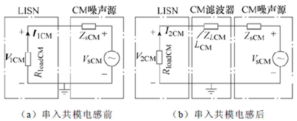
图1 共模噪声源阻抗测试等效电路
Fig.1 CM noise source impedance test circuit
串入共模电感LCM导致的噪声衰减值ATTCM可表示为V1CM和V2CM的比值,即
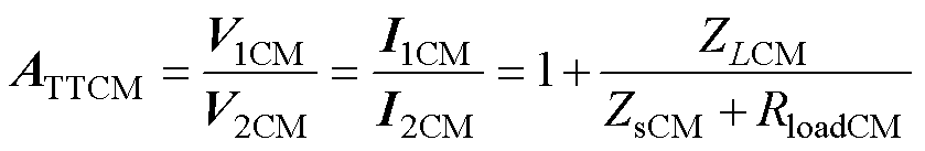 (2)
(2)
式中,ATTCM的幅值为ATTCM。
“传统电压插入损耗法”[25]在共模噪声源和LISN之间串入共模电感,通过测试共模电感插入前后的噪声衰减值的幅值ATTCM,即可确定共模噪声源阻抗幅值的最大可能值|ZsCM|max_[25]和最小可能值|ZsCM|min_[25]。文献[26]在不改变测试方案的前提下,提出“修正的电压插入损耗法”,推导了共模噪声源阻抗幅值的最大值|ZsCM|max_[26]和最小值|ZsCM|min_[26]的精确解析表达式。
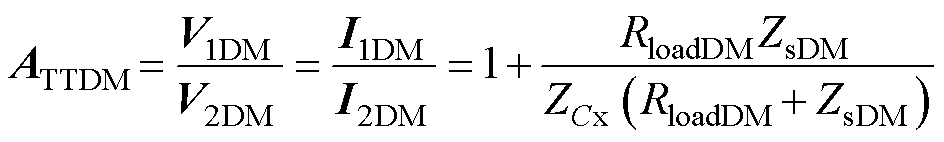
差模噪声源阻抗测试电路等效如图2所示。图2中,ZsDM为差模噪声源阻抗,VsDM为差模噪声电压源;RloadDM为LISN端等效的差模负载阻抗,RloadDM= 100W;ZCx为并入的差模电容Cx阻抗;I1DM和I2DM分别为并入Cx前后LISN端测量得到的噪声电流;V1DM和V2DM分别为并入Cx前后LISN端测量得到的噪声电压。
并入差模电容Cx导致的噪声衰减值ATTDM可表示为V1DM和V2DM的比值,整理为
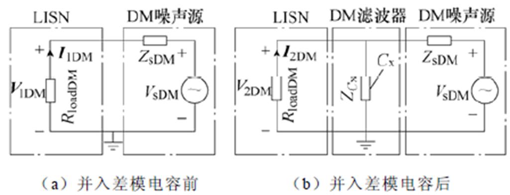
图2 差模噪声源阻抗测试等效电路
Fig.2 DM noise source impedance test circuit
 (3)
(3)
式中,ATTDM为ATTDM的幅值。
“传统电压插入损耗法”[25]计算差模噪声源阻抗幅值与共模噪声源阻抗幅值计算方法类似,通过测试差模电容插入前后的噪声衰减幅值ATTDM,即可确定差模噪声源阻抗幅值的最大可能值|ZsDM|max_[25]和最小可能值|ZsDM|min_[25]。文献[26]同样推导了差模噪声源阻抗幅值的最大值|ZsDM|max_[26]和最小值|ZsDM|min_[26]的精确解析表达式。
针对“电压插入损耗法”只能计算噪声源阻抗幅值的范围,且无法求解相位的问题,本文提出基于插入无源二端口网络的噪声源阻抗提取方法,通过在被测设备与LISN之间插入3个不同的无源二端口网络,建立关于噪声源阻抗实部和虚部的二元二次方程组,运用数学软件编程筛选传导EMI测试频段(9kHz~30MHz)范围内测试的有效频点噪声电流,计算求得其对应的噪声源阻抗幅值和相位的精确值,进而可以预测插入EMI滤波器后LISN端的噪声电流。
所提噪声源阻抗提取方法测试等效电路如图3所示。图中,Zs为噪声源阻抗;Vs为噪声电压源;Ni为插入的第i个无源二端口网络,取i=1, 2, 3,其中的无源元件(R、L、C)的精确阻抗特性曲线可用阻抗分析仪测得;Ii为插入无源二端口网络Ni时的电流;RLISN为LISN的等效阻抗,其等效阻抗值取决于噪声源阻抗实验类型。当测试共模噪声时,RLISN=RloadCM;当测试差模噪声时,RLISN=RloadDM;Zi为插入无源二端口网络Ni时端口 的输入阻抗,可通过端口内部阻抗的串并联等效得到。V1和V2分别为端口和端口
 的端口电压。
当图3中端口以左部分电路被输入阻抗Zi等效替代后,噪声源阻抗测试电路可等效为所提噪
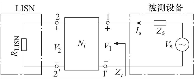
图3 所提噪声源阻抗提取方法测试等效电路
Fig.3 Test circuit of the proposed noise impedance extraction method
声源阻抗提取方法测试等效电路如图4所示。为了得到噪声源阻抗Zs的幅值|Zs|和相位 ,记Zs的实部和虚部分别为Zs_Re和Zs_Im,则端口输入阻抗Zi的实部和虚部分别为Zi_Re和Zi_Im。当插入无源二端口网络Ni时,噪声电流Ii可取模表示为
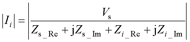 (4)
(4)
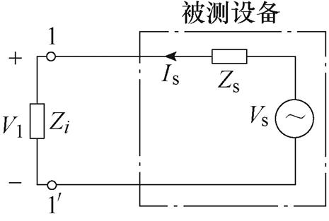
图4 所提噪声源阻抗提取方法测试等效电路
Fig.4 Test equivalent circuit of the proposed noise source impedance extraction method
为了建立噪声源阻抗实部Zs_Re和虚部Zs_Im与可被测量之间的关系,通过插入3个不同的无源二端口网络Ni后,由式(4)可建立关于噪声源阻抗实部Zs_Re和虚部Zs_Im的二元二次方程组为
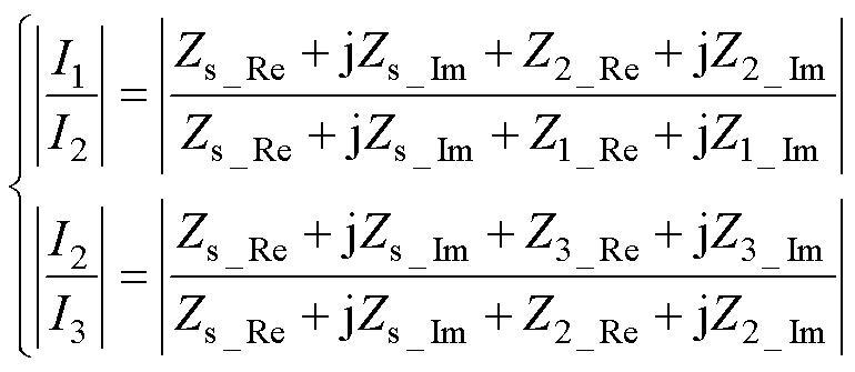 (5)
(5)
式中,噪声电流Ii、输入阻抗的实部Zi_Re和虚部Zi_Im均可通过实验测量获得,仅有噪声源阻抗实部Zs_Re和虚部Zs_Im为未知量。在传导EMI测试频段范围内,采用EMI接收机测量得到各频点的噪声电流数据,并通过数学软件平台编写程序自动循环求解每个频点对应的二元二次方程组,容易得到噪声源阻抗Zs的实部Zs_Re和虚部Zs_Im。
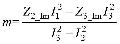
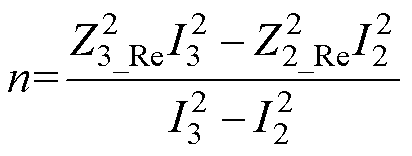
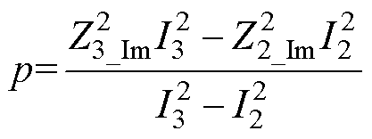
但是,在求解噪声源阻抗的过程中,由于受到测量误差、测试环境和线路高频寄生参数等不确定因素的影响,若干频点下的噪声源阻抗数据求解将无法收敛。因此,需要判断二元二次方程组式(5)是否有解以筛选有效频率点集fm。若将噪声源阻抗Zs的实部Zs_Re和虚部Zs_Im分别当作自变量和因变量,则二元二次方程组式(5)可表示为关于噪声源阻抗实部Zs_Re的函数Zs_Im1(Zs_Re)和Zs_Im2(Zs_Re),即
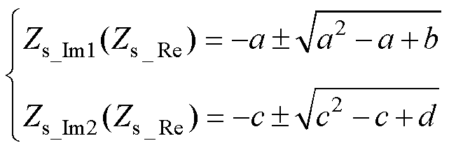 (6)
(6)
其中
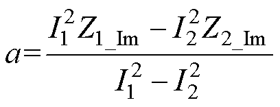
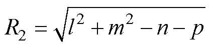
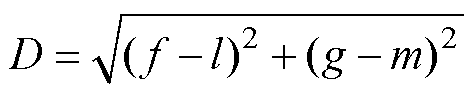
噪声源阻抗解集轨迹如图5所示,函数Zs_Im1(Zs_Re)和Zs_Im2(Zs_Re)的图像为两个圆轨迹,当两个圆轨迹存在交点时,该频率点对应的噪声源阻抗有解。记Zs_Im1(Zs_Re)和Zs_Im2(Zs_Re)对应圆的半径分别为R1和R2,两圆的圆心距为D。
 (7)
(7)
 (8)
(8)
 (9)
(9)
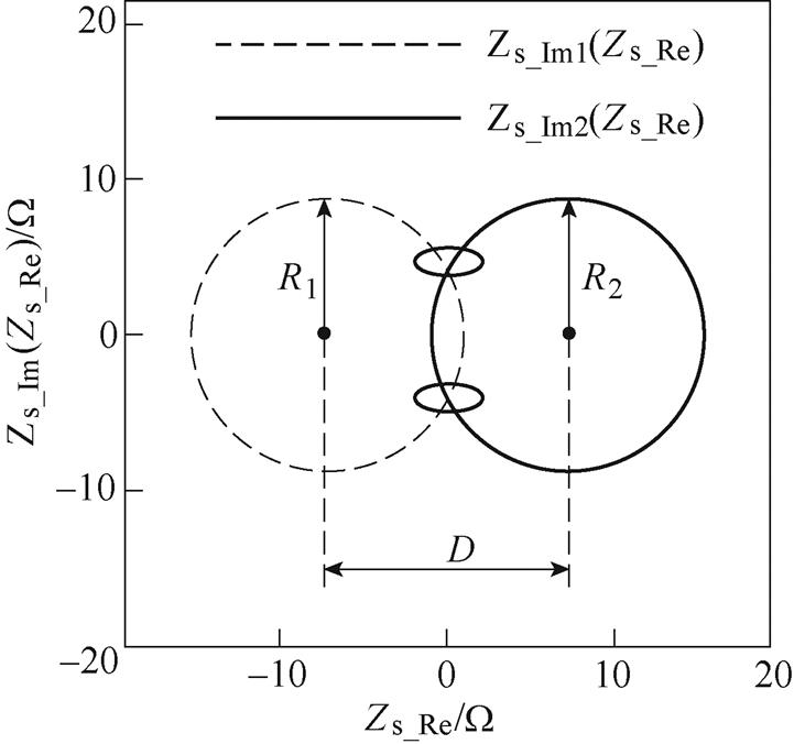
图5 噪声源阻抗解集轨迹
Fig.5 The noise source impedance solution trajectory
其中
根据几何理论知识,两个圆轨迹有交点或二元二次方程组式(5)有解的充分条件为
 &&
&&
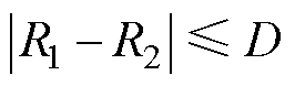 (10)
(10)
结合式(5)、式(7)~式(10),通过编程容易自动得到传导EMI测试频段范围内的有效频点及其对应的噪声源阻抗实部Zs_Re和虚部Zs_Im,进而能够得到噪声源阻抗的幅值|Zs|和相位分别为
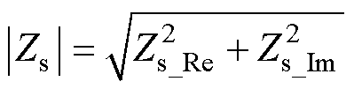 (11)
(11)
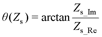 (12)
(12)
上述理论分析对共模噪声源阻抗和差模噪声源阻抗的提取均适用。以图1和图2为例,在获得噪声源阻抗幅值|Zs|和相位后,即噪声源复阻抗Zs,便能通过式(2)和式(3)准确计算插入EMI滤波器后的噪声衰减值,从而预测插入EMI滤波器后LISN端的噪声电流I2CM和I2DM。
但是,对于“电压插入损耗法”,由于不能得到噪声源复阻抗Zs,因此无法预测插入EMI滤波器后的噪声衰减值以及LISN端的噪声电流。
因此,噪声源阻抗幅值和相位的求解对于EMI滤波器噪声抑制效果的预测具有重要意义。同样地,噪声源幅值和阻抗相位的求解对基于噪声源阻抗提取的EMI滤波器的设计提供了精确的理论依据。
为了验证所提噪声源阻抗提取方法的正确性,以一台两级式大功率工业照明LED驱动电源为实验对象,电路参数见表1。EMI测试平台按照EN55015标准布局。差共模噪声分离采用电流法,使用的EMI接收机、LISN、电流钳分别为科环世纪的KH3939、KH3763、KH23101。
表1 LED驱动电源电路参数
Tab.1 Parameters of LED driving power supply
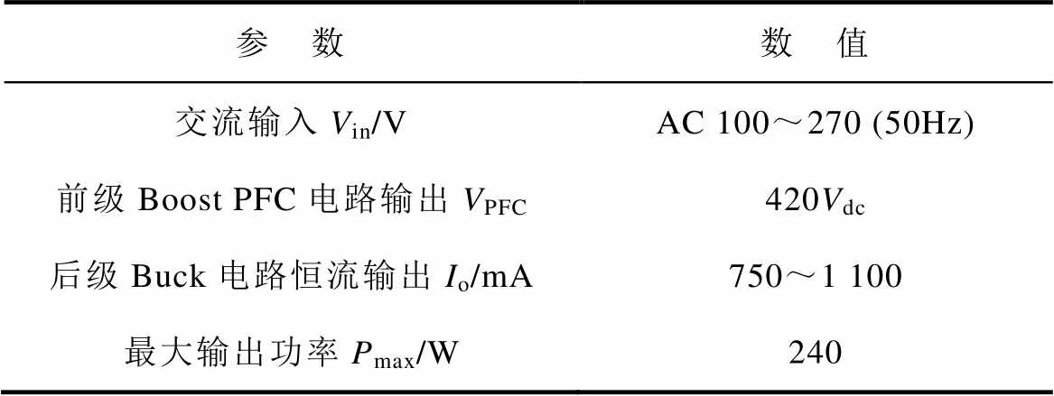
参 数数 值 交流输入Vin/VAC 100~270 (50Hz) 前级Boost PFC电路输出VPFC420Vdc 后级Buck电路恒流输出Io/mA750~1 100 最大输出功率Pmax/W240
根据“电压插入损耗法”,测量共模噪声源阻抗幅值时需要在被测设备与LISN之间串入一个共模电感,选取的共模电感LCM阻抗的高频分布参数见表2中的Zcm1,即ZLCM=Zcm1;测量差模噪声源阻抗幅值时需要在被测设备和LISN之间并入一个差模电容,选取的差模电容Cx阻抗的高频分布参数见表2中的Zdm1,即ZCx=Zdm1。分别测试插入共模电感LCM、差模电容Cx前后的噪声频谱,并计算共模噪声衰减幅值ATTCM和差模噪声衰减幅值ATTDM,插入阻抗导致的噪声衰减幅值如图6所示。
表2 无源二端口网络中阻抗的高频参数
Tab.2 High frequency parameters of the impedance in passive two port networks
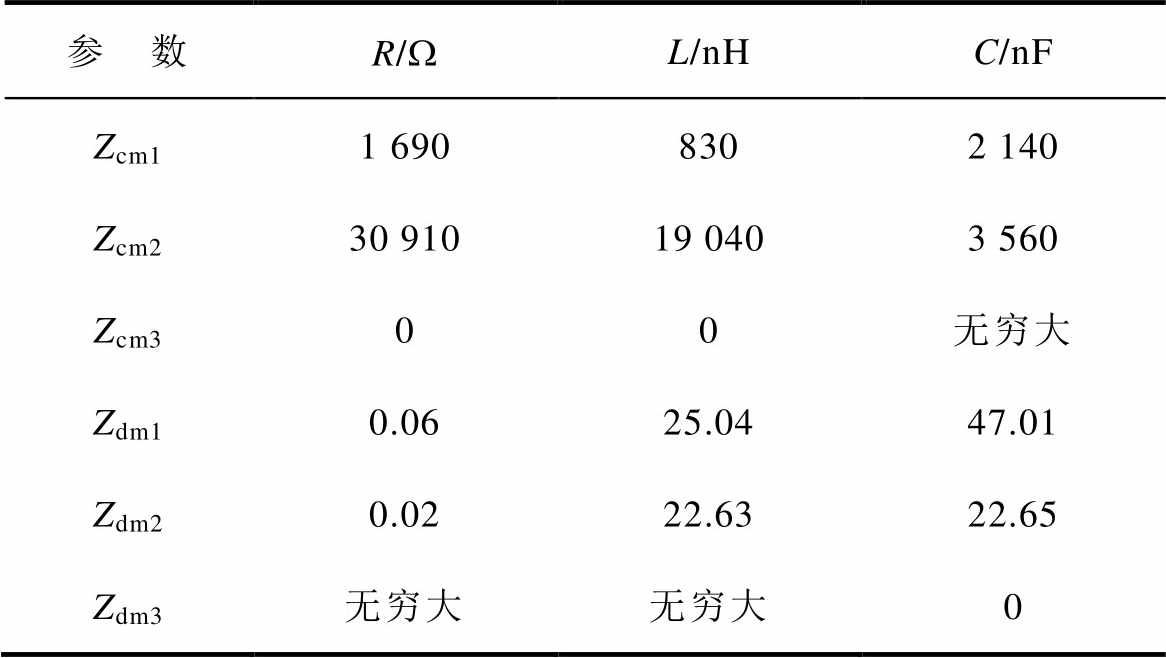
参 数R/WL/nHC/nF Zcm11 6908302 140 Zcm230 91019 0403 560 Zcm300无穷大 Zdm10.0625.0447.01 Zdm20.0222.6322.65 Zdm3无穷大无穷大0
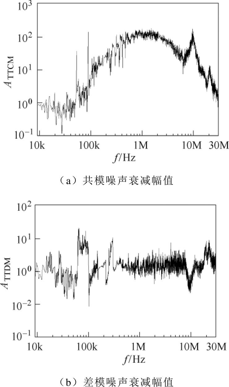
图6 插入阻抗导致的噪声衰减幅值
Fig.6 Noise attenuation caused by insertion impedance
再根据文献[25]方法,就可以得到共模噪声源阻抗幅值的最大和最小可能值为|ZsCM|max_[25]和|ZsCM|min_[25],差模噪声源阻抗幅值的最大和最小可能值为|ZsDM|max_[25]和|ZsDM|min_[25]。
同理根据文献[26]方法,可以得到共模噪声源阻抗幅值的最大和最小值为|ZsCM|max_[26]和|ZsCM|min_[26],差模噪声源阻抗幅值的最大和最小值为|ZsDM|max_[26]和|ZsDM|min_[26]。
所提噪声源阻抗提取方法计算共模噪声源阻抗和差模噪声源阻抗时均需要选取3个不同的无源二端口网络。在实验中,采用3个不同感值的共模电感构造3个如图7a所示的无源二端口网络,其阻抗分别为表2的Zcm1、Zcm2和Zcm3(Zcm3为短路电感阻抗,即电感为零);采用3个不同容值的差模电容构造3个如图7b所示的无源二端口网络,其阻抗分别为表2的Zdm1、Zdm2和Zdm3(Zdm3为开路电容阻抗,即电容为零)。
共模噪声源阻抗提取实验选取图7a二端口网络,其对应的端口输入阻抗Zi等效为Zi=RloadCM+ Zcmi;差模噪声源阻抗提取实验选取图7b二端口网络,其对应的端口输入阻抗Zi可等效为Zi= RloadDM//Zdmi。
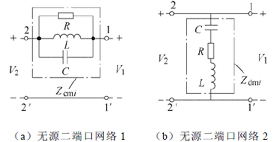
图7 无源二端口网络
Fig.7 Passive two-port network
采用KH23101电流钳测量得到LISN端的噪声电流后根据阻抗的串并联关系就能推导出噪声电流Ii的大小,再根据式(5)、式(7)~式(12)便可求解得到,传导频段范围内的共模噪声源阻抗的幅值|ZsCM|和相位 以及差模噪声源阻抗的幅值|ZsDM|和相位
 ,如图8和图9所示。
“传统电压插入损耗法”[25]“修正的电压插入损耗法”[26]和所提方法计算的噪声源阻抗幅值计算结果如图8所示。
从图8的噪声源阻抗幅值计算结果可以看出,在文献[25]方法的基础上,文献[26]提出的“修正的电压插入损耗法”提高了噪声源阻抗幅值范围的计算精度。而本文所提方法计算出的噪声源阻抗幅值在全频段范围内(9kHz~30MHz)绝大部分都落在了文献[26]方法计算的噪声源阻抗幅值的最大值和最小值之内,进一步提高了计算精度。
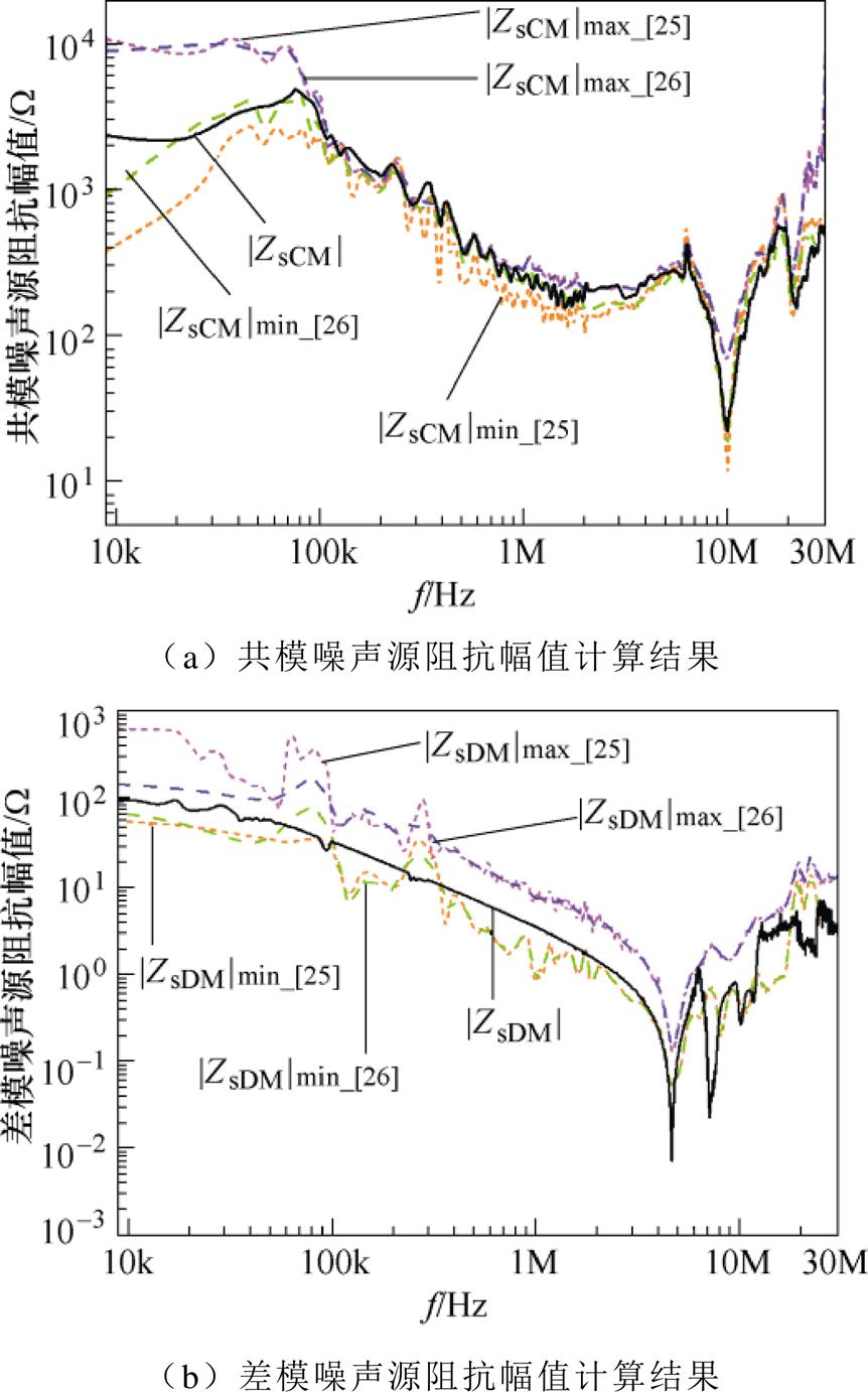
图8 噪声源阻抗幅值计算结果
Fig.8 The calculated amplitude of noise source impedance
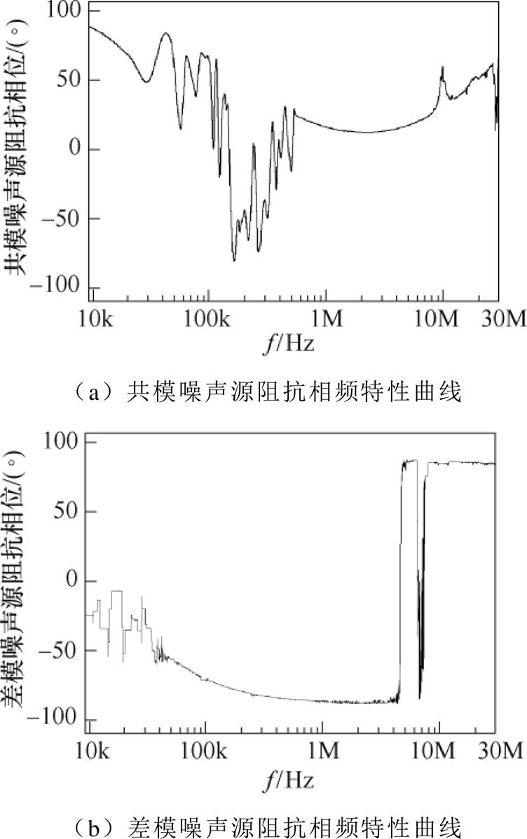
图9 基于所提方法计算的噪声源阻抗相位结果
Fig.9 Phase results of noise source impedance calculated by the proposed method
如图9所示为基于所提方法计算出的共模噪声源阻抗相位 和差模噪声源阻抗相位。所提方法计算的噪声源阻抗幅值是两个圆轨迹的交点,而“电压插入损耗法”计算出的噪声源阻抗幅值为圆轨迹的最大值和最小值。因此,相比“电压插入损耗法”,所提方法噪声源阻抗幅值不仅计算精度更高,而且可以获取噪声源阻抗相位。上述实验结果初步验证了所提方法的正确性。
基于第2节的分析,根据噪声源阻抗Zs的计算结果可以预测插入任意EMI滤波器后LISN端的噪声电流。因此,可将LED驱动电源实验样机工作时实测的噪声电流与预测的噪声电流进行对比,进一步验证所提方法的准确性。
具体验证方法为:在被测设备与LISN之间串入随机取值为470mH的共模电感LCM,如图1所示。在被测设备与LISN之间并入随机取值为68nF的差模电容Cx,如图2所示。
采用阻抗分析仪WK6500B可测量得到LCM和Cx的实测阻抗(包括幅值和相位)特性曲线。由于阻抗分析仪与EMI接收机导出的频点数据不对应,而计算预测噪声电流时采用的原始共模(差模)噪声电流、噪声源阻抗的频点与EMI接收机导出的频点对应。因此,需要对LCM和Cx实测的阻抗值进行拟合,以求得与EMI接收机相同测量频点的阻抗值,如图10所示。
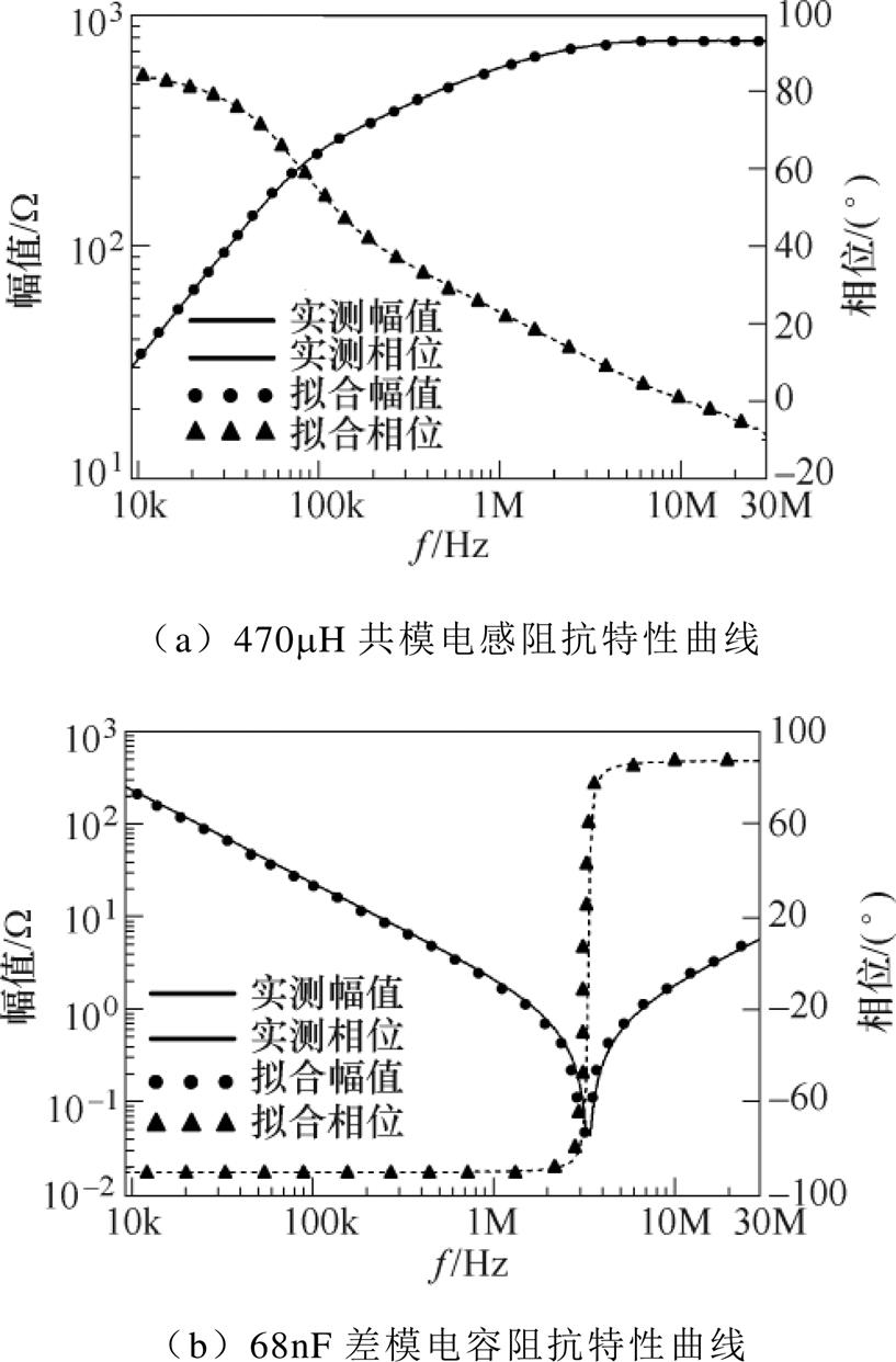
图10 测试元件的阻抗特性
Fig.10 The impedance curves of the test elements
最后,通过传导EMI实验测量获得图1和图2中的原始共模噪声电流I1CM和差模噪声电流I1DM后,再根据共模电感LCM阻抗ZLCM、差模电容Cx阻抗ZCx,以及图8求得的噪声源阻抗ZsCM和ZsDM,结合式(2)和式(3)便能预测共模噪声电流I2CM和差模噪声电流I2DM的大小,与实际测量的噪声电流频谱进行对比,验证效果如图11所示。从图11的噪声频谱对比曲线可以看出,在传导EMI测试频段范围内,所提噪声源阻抗提取方法预测的噪声电流与实际测量的噪声电流吻合良好,验证了所提方法的正确性。
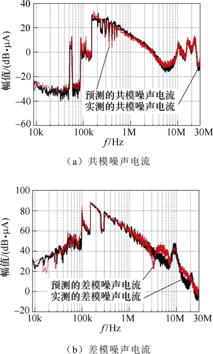
图11 基于所提方法预测的噪声电流与实测的噪声电流对比
Fig.11 Comparison between the measured noise current and the predicted noise current by the proposed method
针对“电压插入损耗法”不能求解噪声源阻抗幅值的精确值以及噪声源阻抗相位,提出一种基于插入无源二端口网络的噪声源阻抗提取方法。新方法在被测设备与LISN之间插入3个任意不同的无源二端口网络,建立了噪声源阻抗实部和虚部的二元二次方程组关系式,并通过编程实现自动化的求解,筛选出传导EMI测试频段(9kHz~30MHz)范围内的有效频点,可以准确地计算噪声源阻抗幅值和相位。
实验结果表明,所提方法求解的噪声源阻抗幅值在传导EMI测试频段范围内绝大部分都落在了“电压插入损耗法”计算的噪声源阻抗幅值范围内,具有更高的精度。同时基于新方法计算的噪声源阻抗可以准确地预测插入EMI滤波器后LISN端的噪声电流,为设计高性能的EMI滤波器提供理论依据。所提方法成本低、操作简单、实用性强,且具有普遍适用性。
参考文献
[1] 何杰, 刘钰山, 毕大强, 等. 开关变换器传导干扰抑制策略综述[J]. 电工技术学报, 2022, 37(6): 1455- 1472.
He Jie, Liu Yushan, Bi Daqiang, et al. Review of conducted electromagnetic interference suppression strategies for switching converters[J]. Transactions of China Electrotechnical Society, 2022, 37(6): 1455- 1472.
[2] 张逸成, 叶尚斌, 张佳佳, 等. 电力电子设备传导噪声抑制措施研究综述[J]. 电工技术学报, 2017, 32(14): 77-86.
Zhang Yicheng, Ye Shangbin, Zhang Jiajia, et al. Review of conducted noise suppression method for power electronic and electrical equipment[J]. Transa- ctions of China Electrotechnical Society, 2017, 32(14): 77-86.
[3] 董纪清, 陈晓威, 林苏斌. 考虑漏磁特性的变压器电磁干扰特性模型[J]. 电工技术学报, 2017, 32(21): 63-72.
Dong Jiqing, Chen Xiaowei, Lin Subin. Electro- magnetic interference model of transformer con- sidering the leakage magnetic field[J]. Transactions of China Electrotechnical Society, 2017, 32(21): 63-72.
[4] 成林, 欧宏, 毕闯, 等. 基于SiC MOSFET的同步Buck变换器电磁干扰噪声分析及预测[J]. 电工技术学报, 2021, 36(增刊2): 627-634, 643.
Cheng Lin, Ou Hong, Bi Chuang, et al. Analysis and prediction of electromagnetic interference noise in synchronous Buck converter with SiC MOSFET[J]. Transactions of China Electrotechnical Society, 2021, 36(S2): 627-634, 643.
[5] 贾圣钰, 赵争鸣, 施博辰, 等. 电力电子系统电磁干扰数值建模分析[J]. 电工技术学报, 2021, 36(11): 2383-2393, 2423.
Jia Shengyu, Zhao Zhengming, Shi Bochen, et al. Numerical modeling and analysis of electromagnetic interference in power electronics systems[J]. Transa- ctions of China Electrotechnical Society, 2021, 36(11): 2383-2393, 2423.
[6] 刘颜, 董光冬, 张方华. 反激变换器共模噪声的抑制[J]. 电工技术学报, 2019, 34(22): 4795-4803.
Liu Yan, Dong Guangdong, Zhang Fanghua. Reducing common mode noise in flyback converter[J]. Transa- ctions of China Electrotechnical Society, 2019, 34(22): 4795-4803.
[7] 林苏斌, 陈为, 董纪清, 等. 开关电源变压器传导共模EMI磁电综合模型[J]. 中国电机工程学报, 2017, 37(8): 2436-2445.
Lin Subin, Chen Wei, Dong Jiqing, et al. Magneto- electric composite model of transformer for con- ducted common-mode EMI in switching-mode power supply[J]. Proceedings of the CSEE, 2017, 37(8): 2436-2445.
[8] Ye Sheng, Eberle W, Liu Yanfei. A novel EMI filter design method for switching power supplies[J]. IEEE Transactions on Power Electronics, 2004, 19(6): 1668-1678.
[9] 江师齐, 王卫, 王盼宝, 等. 一种结构对称型电磁集成电磁干扰滤波器分析与设计[J]. 电工技术学报, 2022, 37(22): 5826-5835.
Jiang Shiqi, Wang Wei, Wang Panbao, et al. Analysis and prototyping of the electromagnetic integration of a structure-symmetrical EMI filter[J]. Transactions of China Electrotechnical Society, 2022, 37(22): 5826- 5835.
[10] 江师齐, 刘艺涛, 银杉, 等. 基于噪声源阻抗提取的单相逆变器电磁干扰滤波器的设计[J]. 电工技术学报, 2019, 34(17): 3552-3562.
Jiang Shiqi, Liu Yitao, Yin shan, et al. Electromag- netic interference filter design of single-phase inverter based on the noise source impedance extraction[J]. Transactions of China Electrotechnical Society, 2019, 34(17): 3552-3562.
[11] Schneider L M. Noise source equivalent circuit model for off-line converters and its use in input filter design[C]//1983 IEEE International Symposium on Electromagnetic Compatibility, Arlington, VA, USA, 1983: 1-9.
[12] See K Y, Deng Junhong. Measurement of noise source impedance of SMPS using a two probes approach[J]. IEEE Transactions on Power Electronics, 2004, 19(3): 862-868.
[13] Tarateeraseth V, Hu Bo, See K Y, et al. Accurate extraction of noise source impedance of an SMPS under operating conditions[J]. IEEE Transactions on Power Electronics, 2010, 25(1): 111-117.
[14] Tarateeraseth V. EMI filter design part II: measure- ment of noise source impedances[J]. IEEE Electro- magnetic Compatibility Magzine, 2012, 1(1): 42-49.
[15] Fan Fei, See K Y, Liu Xiong, et al. Systematic common- mode filter design for inverter-driven motor system based on in-circuit impedance extraction[J]. IEEE Transactions on Electromagnetic Compatibility, 2020, 62(5): 1711-1722.
[16] Zhao Bo, Zhao Min, Feng Zhiming, et al. Standard resistor calibration method in measurement of noise source impedance using dual-probe approach[C]// 2009 5th Asia-Pacific Conference on Environmental Electro-magnetics, Xian, China, 2009: 408-411.
[17] Ye Xin, Liu Yitao, Jiang Shiqi, et al. Extraction of noise source impedance under operating conditions using a two- probe approach[C]//2020 IEEE 9th International Power Electronics and Motion Control Conference, Nanjing, China, 2020: 1858-1862.
[18] Qiu Xiaohui, Yang Z, See K Y, et al. An efficient noise source impedance estimation approach applied in electromagnetic compatibility[J]. Chinese Journal of Electronics, 2009, 18(4): 744-748.
[19] Zhao Yang, Lu Xiaoquan, Dong Yinghua, et al. Study on impedance extraction methods applied in con- ductive EMI source modeling[C]//Asia Pacific International Symposium on Electromagnetic Com- patibitity, Beijing, China, 2010: 998-1001.
[20] Li Jinlong, Ma Shiping, Yin Xuebin, et al. Mea- surement of common-mode and differential-mode noise source impedances using a current probe and single path LISNs[C]//Joint International Symposium on Electromagnetic Compatibility, Sapporo and Asia-Pacific International Symposium on Electro- magnetic Compatibility (EMC Sapporo/APEMC), Sapporo, Japan, 2019: 641-644.
[21] 颜伟, 赵阳, 王恩荣, 等. 基于双阻抗校准和麦夸尔特法的阻抗提取[J]. 中国电机工程学报, 2013, 33(21): 178-183, 208.
Yan Wei, Zhao Yang, Wang Enrong, et al. Impedance extraction method based on dual impedance calibration and Levenberg-Marquardt’s algorithm[J]. Proceedings of the CSEE, 2013, 33(21): 178-183, 208.
[22] 王世山, 龚敏, 宋峥. 基于散射参数法的EMI滤波器电磁噪声抑制效果预测[J]. 电工技术学报, 2016, 31(18): 66-74.
Wang Shishan, Gong Min, Song Zheng. Predicting the suppression effect of EMI filter based on the sparameter method[J]. Transactions of China Electro- technical Society, 2016, 31(18): 66-74.
[23] Zheng Feng, Wang Wugang, Zhao Xiaofan, et al. Identifying electromagnetic noise-source impedance using hybrid of measurement and calculation method[J]. IEEE Transactions on Power Electronics, 2019, 34(10): 9609-9618.
[24] Zhou Mengxia, Zhao Yang, Yan Wei, et al. Investigation on conducted EMI noise source impedance extraction for electro magnetic com- patibility based on SP-GA algorithm[J]. IET Power Electronics, 2019, 12(7): 1792- 1799.
[25] Zhang Dongbing, Chen D Y, Nave M J, et al. Measurement of noise source impedance of off-line converters[J]. IEEE Transactions on Power Elec- tronics, 2000, 15(5): 820-825.
[26] 张佳佳, 张逸成, 韦莉, 等. 基于插入损耗的噪声源阻抗修正计算方法[J]. 电工技术学报, 2015, 30(4): 80-87.
Zhang Jiajia, Zhang Yicheng, Wei Li, et al. A revised calculation method for noise source impedance based on insertion loss[J]. Transactions of China Electrote- chnical Society, 2015, 30(4): 80-87.
Research on Noise Soure Impedance Extraction Method Based on Inserting Passive Two-Port Network
Abstract Insertion loss (IL) of EMI filter is closely related to noise source impedance and load impedance. Therefore, in order to make the EMI filter design achieve the expected IL and achieve good noise suppression effect, it is necessary to consider the impact of noise source impedance. The voltage insertion loss method can only calculate the maximum and minimum values of the amplitude of the noise source impedance, and cannot solve the phase of the noise source impedance. To solve the above problems, this paper proposes a noise source impedance extraction method based on inserting passive two-port network without adding experimental equipment. Combined with experimental measurement and theoretical calculation, the accurate values of the amplitude and phase of the noise source impedance are obtained.
First, insert three different passive two-port networks between the equipment under test (EUT) and the linear impedance stabilization network (LISN). Secondly, the equivalent circuit of noise source impedance extraction is established, and then the binary quadratic equations about the real part and imaginary part of the noise source impedance are established according to the equivalent circuit. Finally, through the programming of the mathematical software platform, the binary quadratic equations corresponding to each frequency point are solved automatically and circularly, and the effective frequency points measured experimentally in the conducted EMI test frequency band (9kHz~30MHz) are selected, so that the real and imaginary parts of the noise source impedance can be obtained, and then the accurate calculation of the amplitude and phase of the noise source impedance can be realized.
The experimental results show that, no matter the common mode (CM) noise source impedance or the differential mode (DM) noise source impedance, most of the amplitudes of the noise source impedance calculated by the proposed method fall between the maximum and minimum values of the amplitudes of the noise source impedance calculated by the voltage insertion loss method in the conducted EMI test frequency band (9kHz~30MHz), which further improves the calculation accuracy of the amplitude of noise source impedance. In addition, the proposed method can also obtain the exact phase of the noise source impedance, which is not available in the voltage insertion loss method. Finally, the noise current predicted by the proposed noise source impedance extraction method is compared with the noise current actually measured when the LED driver is working. The experimental results show that the two are in good agreement, which further verifies the correctness and effectiveness of the proposed noise source impedance extraction method.
The following conclusions can be drawn from the experimental analysis: ① Compared with the voltage insertion loss method, the amplitude of noise source impedance calculated by the proposed method has higher accuracy, and the phase of noise source impedance can also be obtained. ② At the same time, the noise source impedance calculated based on the proposed method can accurately predict the noise current of LISN after inserting EMI filter, which provides a theoretical basis for designing high-performance EMI filter. ③ The proposed method has the advantages of low cost, simple operation, strong practicability and universal applicability.
Keywords:Electromagnetic interference (EMI), noise source impedance, insertion loss, EMI filter
中图分类号:TN713
DOI: 10.19595/j.cnki.1000-6753.tces.220268
国家自然科学基金资助项目(51207025, 52107183)。
收稿日期 2022-03-01
改稿日期 2022-06-11
E-mail: 1141234378@qq.com
毛行奎 男,1978年生,博士,教授,研究方向为电力电子高频磁技术、新能源发电与储能技术和无线电能传输技术。
E-mail: mxk782@fzu.edu.cn(通信作者)
(编辑 陈 诚)