一种三相对称系统快速谐波检测算法
叶宗彬1 侯 波1 张延澳1 秦嘉盛1 张旭隆2
(1. 中国矿业大学电气与动力工程学院 徐州 221116 2. 徐州工程学院电气与控制工程学院 徐州 221018)
摘要 有源电力滤波器(APF)在谐波治理方面有着广泛应用,其谐波补偿性能在很大程度上取决于谐波检测环节的性能。为了提升谐波检测速度,该文提出一种基于滑窗离散傅里叶变换(SDFT)的快速谐波检测算法。相较于传统滑窗离散傅里叶算法存在一个基波周期延时,该文提出的快速谐波检测算法利用三相系统的对称性,替换传统滑窗离散傅里叶变换谐波检测算法的梳状滤波器构成环节,能在1/6个基波周期内实现谐波的有效检测,降低检测延迟。该文首先分析传统滑窗离散傅里叶变换谐波检测算法的优缺点;其次推导所提出的快速谐波检测算法的Z域表达式并分析其特点;最后通过仿真及小功率缩比有源电力滤波器样机实验平台验证了所提出的快速谐波检测算法的有效性。
关键词:离散傅里叶变换 特定次谐波检测 有源电力滤波器 滑窗迭代
0 引言
为了早日实现“碳达峰,碳中和”的目标,新能源分布式发电比重不断提高,但是其中的高频电力电子装置等非线性设备会造成电网中的谐波污染日益严重[1-2]。为有效治理谐波污染,设计了多种补偿装置,如统一电能质量调节器(Unified Power Quality Conditioner, UPQC)[3]、有源滤波器(Active Power Filter, APF)。其中,有源电力滤波器以其补偿灵活、容量大等特点,在谐波治理领域有着广泛应用[4-8]。由于负载电路含有非线性器件,使得负载电流产生谐波分量,通过谐波检测环节检测出负载电流中的谐波分量并控制变流器产生与谐波分量幅值相同、相位相反的电流,从而避免谐波电流注入电网。因此,有源电力滤波器的功能实现主要由谐波检测和谐波跟踪两部分组成,而谐波检测部分能否快速准确地检测出谐波分量是影响APF性能的一个重要因素[4-5]。在谐波治理系统中,谐波检测方法主要包含时域和频域两个方面。
在众多时域谐波检测算法中,基于瞬时无功功率理论[9-14]的谐波检测算法是谐波检测中重要的一类算法,如 检测法、
检测法、 检测法和d-q检测法[12-14]。
 检测法主要适用于三相对称系统,当电网电压发生畸变时检测误差会增大。
 检测法解决了
 检测法存在的检测精度问题,能够在三相电网电压不平衡和发生畸变时保持较高的检测精度,因此在APF系统中得到广泛应用。但是这种方法主要适用于谐波全补偿,不利于特定次谐波补偿的实现。d-q检测法分为基波同步参考坐标系检测(又称基波dq坐标系检测)和谐波同步参考坐标系检测(又称谐波dq坐标系检测)。基波dq坐标系检测是将基波分量和其余谐波分量分离,可以实现谐波整体补偿。而谐波dq坐标系检测是将某一频率分量与其余频率分量分离,可以灵活实现特定次谐波检测,但是这类方法需要进行坐标变换且需要低通滤波器进行滤波,算法性能上很大一部分由低通滤波器的性能决定。文献[15-18]提出一种基于级联延时信号消除(Cascaded Delayed Signal Cancellation, CDSC)特定次谐波检测算法,基于单一延时信号消除(Delayed Signal Cancellation, DSC)法的模块可以消除一组特定的谐波分量,CDSC将不同构造的DSC模块级联以分离所需分量并滤除其余分量。虽然CDSC可以较快地实现特定次谐波的检测,但是当提取不同谐波分量时需要不同的级联DSC模块,从而增加系统的复杂性、计算量以及存储空间开销。
离散傅里叶变换(Discrete Fourier Transform, DFT)[19-20]作为一种典型的频域谐波检测方法可以实现对指定次谐波检测,但是存在计算量大、延时长等缺点。为减少实时系统计算负担,文献[5, 21-24]将滑窗迭代算法引入离散傅里叶变换中,提出滑窗迭代离散傅里叶(Sliding-window Discrete Fourier Transform, SDFT)谐波检测算法。SDFT的输出频率单元数据与输入数据速率相同,即输入增加一个点的同时输出也增加一个点。因此在实时计算系统中,SDFT相较于Goertzel算法所需计算量更少[25],当只检测某一或几个频率分量时,SDFT比传统的基2时间抽取快速傅里叶变换(Fast Fourier Trans- form, FFT)法[26]更简便。但是SDFT依旧存在一个基波周期的延迟,不利于实现谐波分量实时快速检测。文献[27]提出一种改进的方法,二次采样递归离散傅里叶变换(Twice Sampling Recursive Discrete Fourier Transform, TS-RDFT),可根据输入信号的频谱分布对梳状滤波器重新设计,去除不需要的零点,降低检测算法的延迟。
本文提出一种适用于三相对称系统的新SDFT算法。在三相对称系统中,abc三相信号幅值相同,相位相差 ,且三相信号不含有偶次谐波分量。根据上述三相信号特点,对SDFT谐波检测算法进行改进,能在1/6个基波周期内得到所需频率分量的实部和虚部分量,再进行对应频率分量重构过程,最终实现特定次谐波的快速有效检测。
本文介绍了DFT算法原理和提出的快速谐波检测算法原理的详细推导过程,通过仿真及实验对快速谐波检测算法的可行性进行验证。
1 算法原理
1.1 DFT算法原理
在三相系统中,三相畸变信号可以表示为
式中, 、
、 、
、 为三相实信号;
 为谐波次数;
 、
、 、
、 为三相信号第
 次谐波的幅值;
 为基波角频率;
 、
、 、
、 为三相信号第
 次谐波的相位。
利用欧拉公式,式(1)中三相实信号可以分别由两个共轭复信号之和构成,因此三相信号第 次谐波的复数表达式为
令
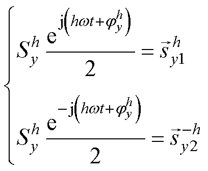 (3)
(3)
式中,y=a, b, c; 为三相信号第h次谐波的幅值;
 为三相信号第h次谐波的相位;
 、
、 为可以构成三相信号第
 次谐波
次谐波 的两个共轭复信号。
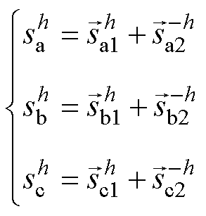
将式(3)代入(2)中得
由式(4)可以看出,三相实信号第 次谐波分量
次谐波分量 由两个共轭复信号
 、
、 之和得到,且
 和
和 有相同的幅值,角频率分别为
 和
和 。
。
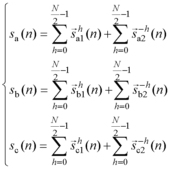
考虑到在离散系统中,对三相信号 、
、 和
和 在一个基波周期内进行
 次采样。根据香农采样定理,当采样信号大于有效信号最高频率的2倍时,采样值中包含原始信号的所有信息,被采样信号可以不失真地还原成原始信号。因此,能从采样信号中获得的最大频率分量为
 ,其中
,其中 为采样频率,
 ,
, 为基波角频率。式(2)的离散化表达式为
根据文献[5],标准复信号输入的 点DFT表达式为
 (6)
(6)
式中, 为时域信号
为时域信号 的采样值;
的采样值; 为第
为第 次谐波频率分量的DFT输出值。而第
 次谐波频率分量的时域表达式由式(6)的DFT反变换得到
式中, 为第
为第 次谐波频率分量的检测结果。
根据式(6)、式(7)可获得第 次谐波频率分量的时域表达式。但是直接计算需要
 个复数乘法运算,计算量大。因此,文献[28]提出SDFT算法以减少计算量。
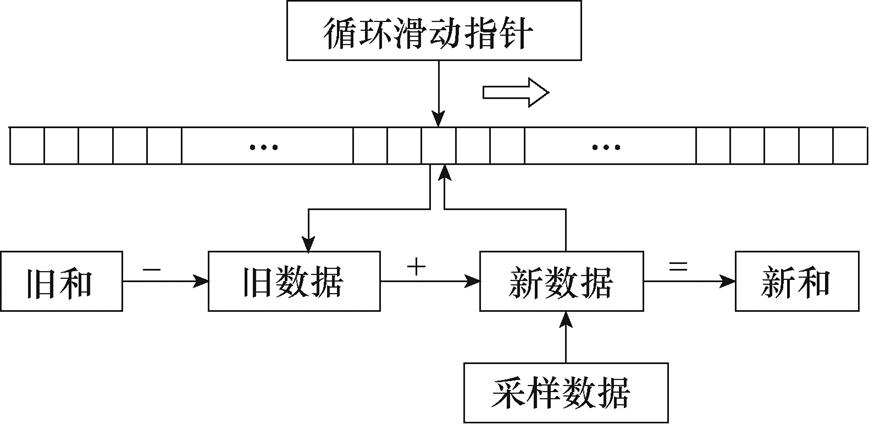
滑窗迭代算法模型如图1所示。采样数据与其对应的旋转因子乘积存储在连续的存储空间内,当采样数据更新为最新采样点时,通过数据运算循环指针定位当前数据存储位置,用最新数据代替老数据以实现数据更新,计算量减少至一个复数乘法运算。
为了更简便地分析式(6)~式(8)表示的DFT谐波检测原理,通过 变换得到DFT谐波检测的
 域传递函数为
其中

式中, 为第
为第 次谐波频率分量检测结果
 (复数)与输入信号
 (复数)的
(复数)的 域传递函数。式(9)表明传递函数
 由三部分组成:梳状滤波器
 、复谐振器
、复谐振器 和增益系数
和增益系数 。
。
通过以上分析,标准DFT谐波检测的 域传递函数如式(9)所示,输入信号为复输入序列。但是,大部分DFT的物理输入是实数(如三相电压、电流采样值),即实输入序列实部为采样值,虚部为零。以A相信号
 为例,根据式(2),实输入序列可由两个共轭复输入序列构成。因此,实输入序列第
 次谐波频率分量检测的
 域传递函数(证明见附录)可以表示为
 (10)
(10)
其中
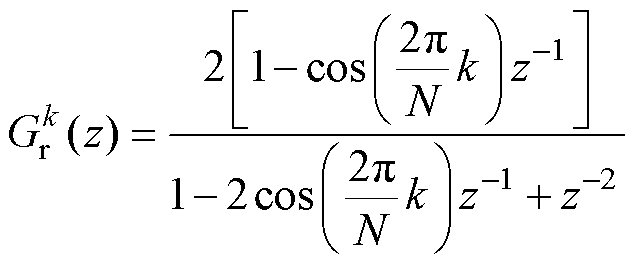
式中, 为输入序列为实数时的传递函数。
式(10)表明,实输入序列的传递函数 由复输入序列传递函数
 和
和 之和表示,谐振器
 由第
由第 次谐波的复谐振器
 和第
和第 次谐波的复谐振器
 构成,梳状滤波器和增益系数不变。假设
 ,
, ,
, ,图2为
,图2为 提取5次谐波频率分量的幅频响应曲线。
1.2 一种快速谐波检测算法
通过以上分析,SDFT谐波检测算法可以精确检测出任意采样信号的第 次谐波频率分量,且只需要一个复数乘法运算。相较于DFT算法需要
 个复数乘法运算,计算量大大减少。但是SDFT谐波检测算法依旧需要一个基波周期才能获得有效的检测结果,动态性能较差。
因此,为了改善检测算法的动态性能,本文提出一种快速谐波检测方法。在三相信号对称时,只需要1/6个基波周期即可获得检测信号的有效结果,三相信号不对称时,只需要1/3个基波周期即可获得检测信号的有效结果。
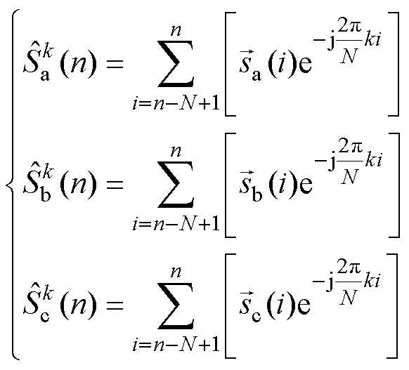
三相信号 、
、 和
和 的标准DFT表达式为
式中, 、
、 、
、 为三相信号第
 次谐波频率分量的DFT输出值;
 、
、 、
、 分别为三相信号
 、
、 和
和 的采样值。
的采样值。
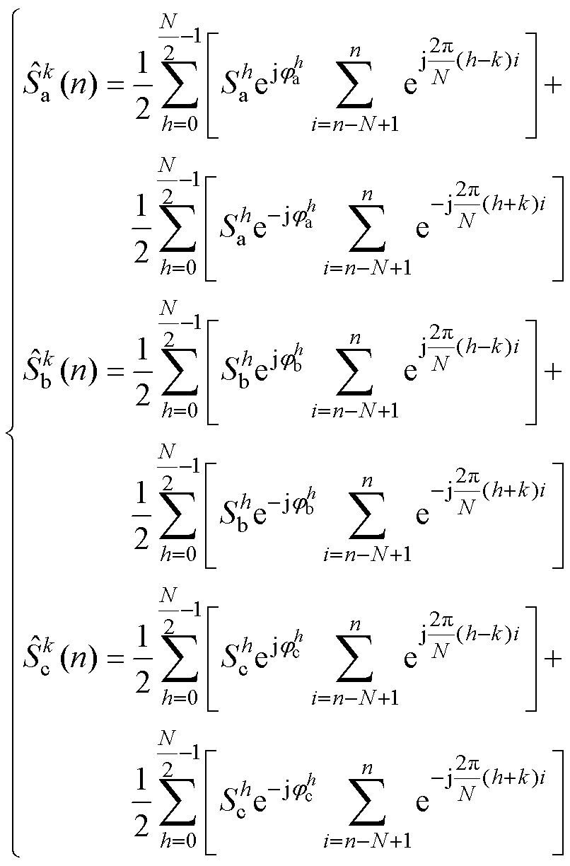
将式(5)代入式(11)得
在三相系统中偶次谐波分量含量很少,可以忽略不计,根据奇谐函数的性质,则
 (13)
(13)
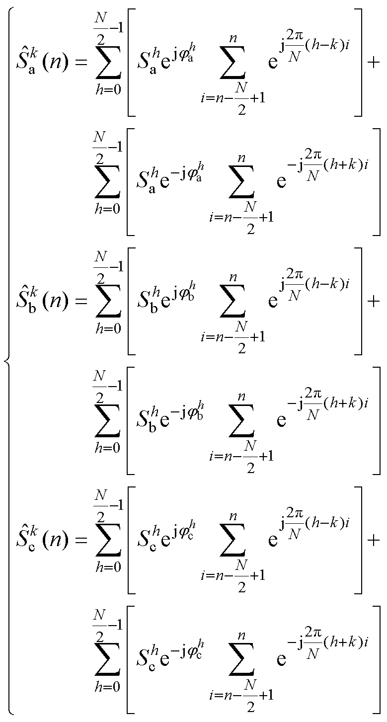
式(12)改写为
即
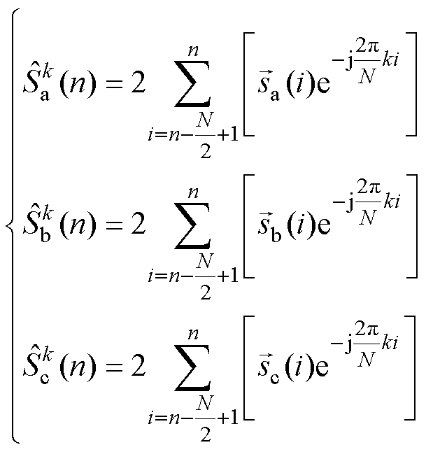 (15)
(15)
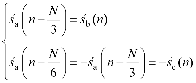
在三相对称系统中,三相信号 、
、 和
和 幅值相同,相位相差
 ,在离散系统中,三相信号之间的关系为
结合式(15)、式(16)中A相DFT表达式, 可以进一步改写为
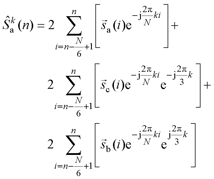 (17)
(17)
式(17)表明,在三相对称系统中,以B、C两相信号的采样值代替A相部分采样值作为DFT计算的输入序列,仅需1/6个基波周期,便可以获得有效待检测谐波频率分量的DFT输出序列。对式(17)进行DFT反变换得到第 次谐波频率分量检测结果的时域表达式
 为
为
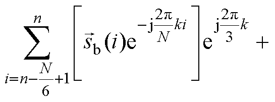
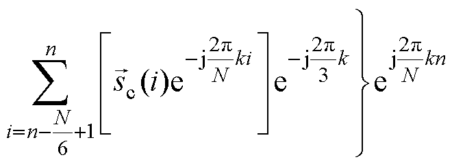 (18)
(18)
对式(18)进行 变换(证明见附录)得
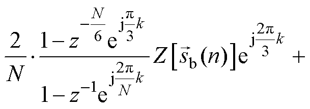
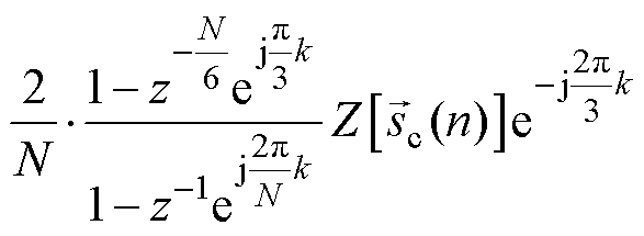 (19)
(19)
对式(16)进行 变换得
变换得
将式(20)代入式(19),得到本文提出方法的等效传递函数为
 (21)
(21)
其中

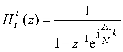
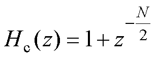
式中, 为本文提出方法的等效传递函数;梳状滤波器为
 如式(22)所示,引入
 个零点以实现
 次谐波频率分量滤除,其中
 。而引入的
。而引入的 个零点导致
个零点导致 个采样周期,即1/2个基波周期的延迟。
式(19)、式(21)表明,
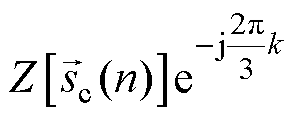 的等效表达式
 中包含的梳状滤波器
 与求取的目标谐波频率分量的频率
 相关,即目标频率不同,滤波器
 构成不同。
构成不同。
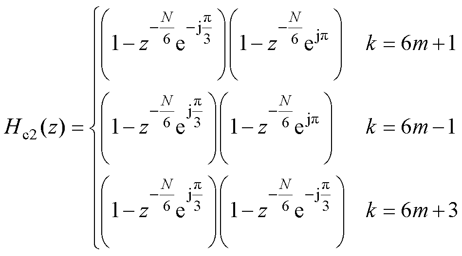
式中, 。式(23)表明,当求取的目标频率
 取不同值时,梳状滤波器
 由
由 、
、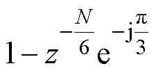 和
和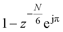 中的两个串联而成,而上述三个梳状滤波器引入
 个零点以分别实现
 、
、 和
和 次谐波频率分量滤除。因此,等效梳状滤波器
 引入
引入 个零点,产生1/3个基波周期的延迟。在本文提出的方法中,梳状滤波器
 的功能包含在
 中,是由B、C两相数据替换A相数据在频域中的表达,因此不产生实际的延迟。而整个检测过程的延迟都是由梳状滤波器
 产生,为1/6个基波周期延迟。
虽然整个等效传递函数中梳状滤波器 实现
实现 次谐波频率分量滤除,但是由于式(16)成立的前提为三相信号对称,因此待检测信号中不能同时含有
 和
和 次谐波频率分量,对
 次谐波频率分量没有限制。
以上分析是基于标准复输入序列DFT,因此根据1.1节的分析,当输入序列为实信号时,可将式(19)改写为
 (24)
(24)
等效传递函数为
式中, 为输入序列为实数时本文提出方法的传递函数。
2 仿真与实验结果分析
2.1 仿真结果分析
为验证本文算法的有效性,分别对SDFT算法和本文提出的快速谐波检测算法仿真模型性能进行测试。在仿真测试中基波频率为50Hz,采样频率为15kHz。
1)仿真测试1:SDFT和本文提出的快速谐波检测算法动态性能。
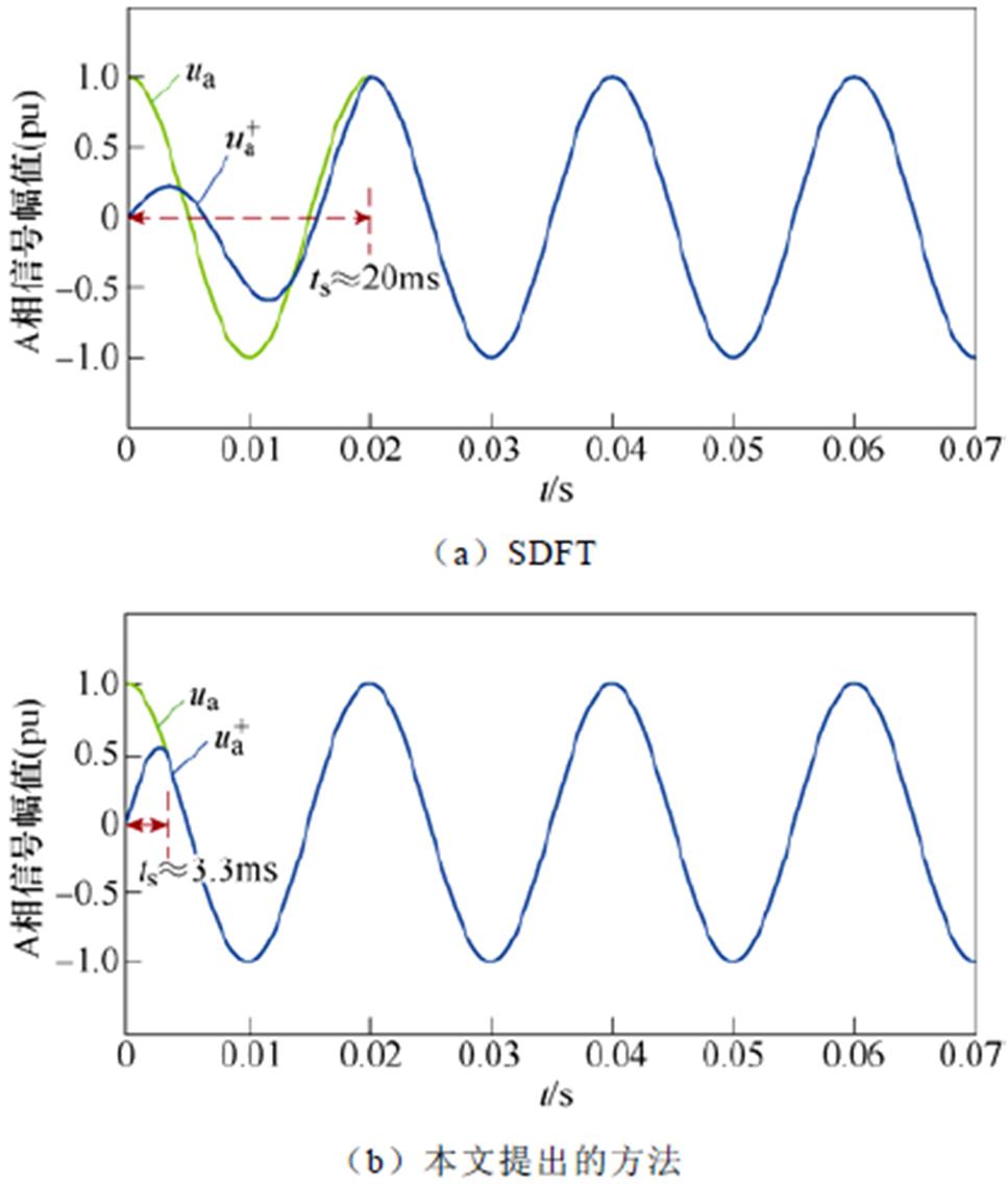
在测试1中,输入信号为三相对称信号,标幺值为1.0(pu)。通过Matlab/Simulink平台进行仿真证明,结果如图3所示。仿真结果表明,SDFT和本文提出的算法都能够实现对目标频率分量的有效检测。但是,采用SDFT需要约20ms才能获得有效的检测结果。而采用本文提出的方法仅需约3.3ms,即1/6个SDFT延迟时间就可以获得有效的检测结果。
2)仿真测试2:三相畸变信号检测。
为更好地验证算法的可行性,将两种检测方法用于检测三相不控整流电路产生的谐波信号。
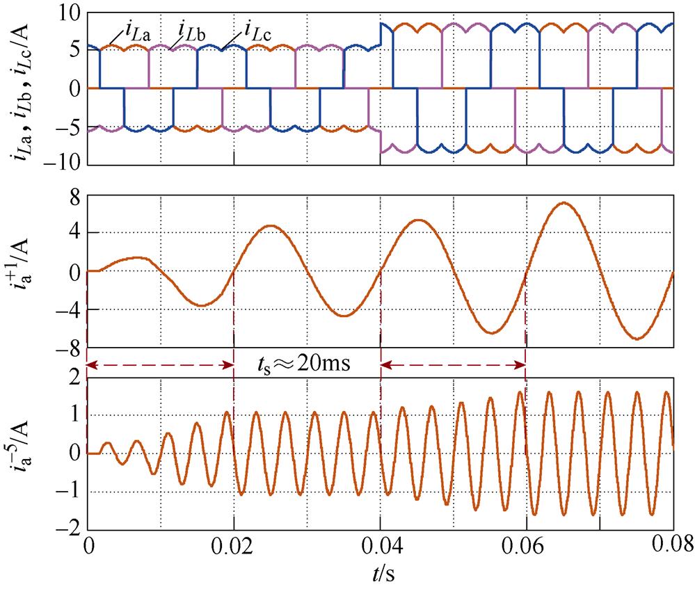
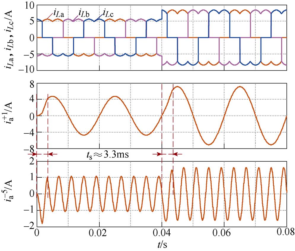
仿真电路负载由三相不控整流电路带30W(20W 与10W 串联)电阻负载作为非线性负载组成,电网线电压为95V。作为典型的非线性负载,三相不控整流器产生 次谐波信号。用SDFT进行谐波检测的仿真波形如图4所示。当三相不控整流电路投入运行时,产生畸变的电流,基波正序和5次负序分量在经过20ms的波动后进入稳态。在0.04s时,负载由30W 突变为20W,在0.06s时获得准确的检测结果。本文提出方法的仿真波形如图5所示,表明本文提出的方法可以在3.3ms延迟内获得准确的检测结果,与SDFT相比减少了延迟时间。
2.2 实验结果分析
将本文提出的方法与SDFT应用于APF系统,补偿由三相不控整流电路产生的谐波,从而验证两种检测方法对APF动态性能的影响。
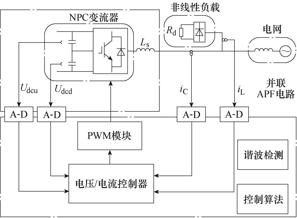
实验装置由三相并联有源电力滤波器(APF)和三相不控整流桥带纯电阻负载组成,APF系统电路及控制策略如图6所示。
APF主电路采用三电平中点钳位(Neutral Point Clamped, NPC)型变流器结构,控制策略为重复控制,采用数字信号处理器(DSP28335)来实现算法控制。实验主要参数见表1。
表1 实验的系统参数
Tab.1 System parameters for experiment
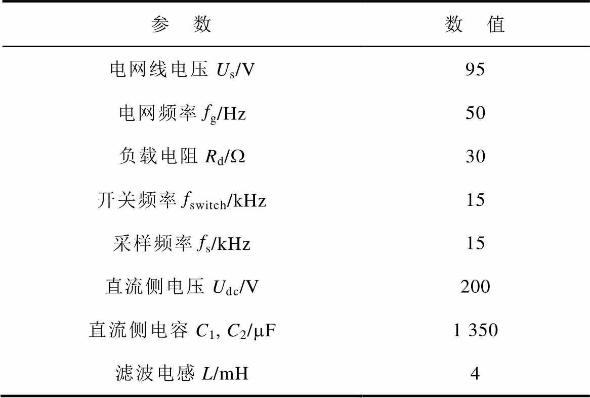
参 数数 值 电网线电压Us/V95 电网频率fg/Hz50 负载电阻Rd/W30 开关频率fswitch/kHz15 采样频率fs/kHz15 直流侧电压Udc/V200 直流侧电容C1, C2/mF1 350 滤波电感L/mH4
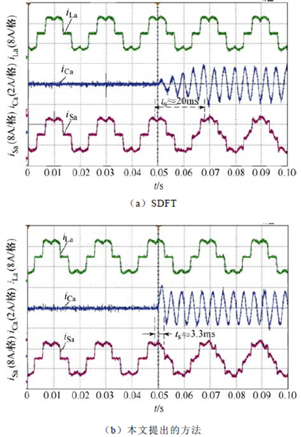
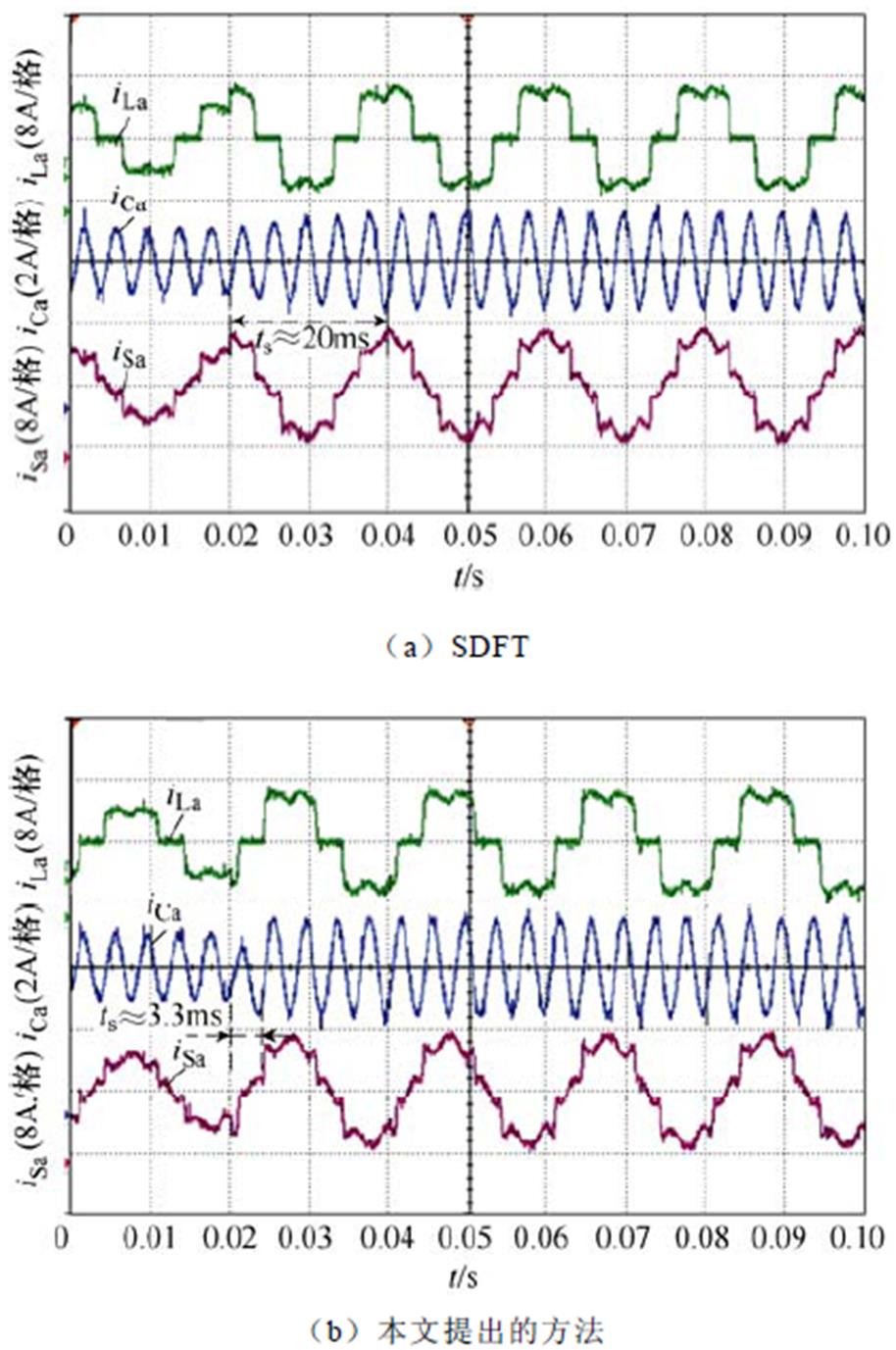
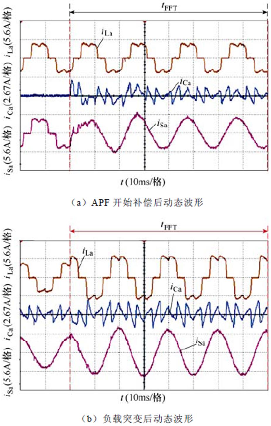
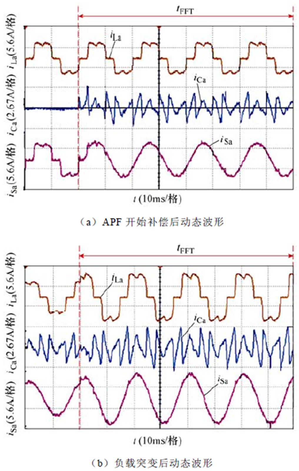
采用SDFT和本文提出的方法对三相不控整流电路产生的负序5次谐波电流分量进行检测提取。检测结果作为电流内环谐波电流参考值,对负序5次谐波电流分量进行补偿。实验波形如图7、图8所示,图中, 、
、 、
、 分别为A相负载电流、谐波参考电流、电网电流。图7a和图7b分别展示了采用SDFT和本文提出的方法的实验波形的动态过程。图8展示了负载突变时两种检测方法对应的实验波形。以上实验结果表明,SDFT和本文提出的方法都能实现特定次谐波检测,但是本文提出的方法比SDFT具有更好的动态响应过程且需要更少的存储空间。
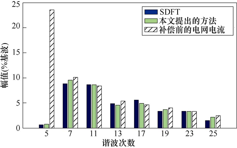
用SDFT和本文提出方法消除特定次谐波之后A相电网电流的FFT结果如图9所示,在采用SDFT和本文提出的方法的APF系统对5次谐波电流分量补偿后,电网电流5次谐波电流含有率 分别由23.56%降至0.64%和0.77%。
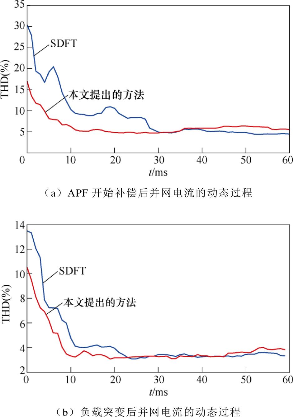
图10和图11分别展示了采用SDFT和本文提出方法的APF投入运行和负载突变时的动态波形。图10和图11表明,采用本文提出方法的APF系统并网电流更快地进入稳态。为更直观地展现动态性能,对 时间段内的并网电流作FFT分析,实验结果如图11所示,表明采用本文提出方法的APF表现出更好的动态性能,但是因为实验过程中存在采样误差,导致达到稳态时并网电流的谐波含量偏高[29]。
3 结论
SDFT谐波检测算法存在长延时的缺陷,为此本文提出一种适用于三相对称系统中的快速谐波检测算法,能够实现特定次谐波快速有效的检测。仿真结果表明,本文提出的方法具有更快的动态响应,只需要1/6个基波周期就可以实现特定次谐波检测。将本文提出的方法应用于APF系统中可以改善系统的动态性能,更快实现对目标频率分量的补偿。
附 录
1. 实输入序列第 次谐波频率分量检测的
 域传递函数的推导
由式(4)可知,实信号 可由两个共轭复信号表示为
将式(A1)代入式(6)可得

式中, 。
。
令
 (A3)
(A3)
 (A4)
(A4)
式(A2)可简化为
对式(A5)进行DFT反变换得到第 次谐波信号在时域的表达式为
 (A6)
(A6)
令
结合式(A6)和式(A7)可以看出,当把实信号作为标准DFT的输入信号,再经过DFT反变换得到的第 次谐波信号的时域表达式只是实信号的一部分,完整的第
 次实信号应为在
 和
和 两处输出信号之和。因此实信号完整的第
 次谐波信号在时域的表达式为
 (A8)
(A8)
对式(A8)进行z变换得
 (A9)
(A9)
传递函数可表示为
 (A10)
(A10)
其中
2. 第 次谐波频率分量检测结果的时域表达式的推导
对式(18)的z变换只需要证明
又因为

式(18)的z变换表达式为

参考文献
[1] 王保帅, 肖勇, 胡珊珊, 等. 适用于非整数次幂的高精度混合基FFT谐波测量算法[J]. 电工技术学报, 2021, 36(13): 2812-2820, 2843.
Wang Baoshuai, Xiao Yong, Hu Shanshan, et al. High precision mixed radix FFT algorithm for harmonic measurement under non-integer power sequence[J]. Transactions of China Electrotechnical Society, 2021, 36(13): 2812-2820, 2843.
[2] 陈杰, 章新颖, 闫震宇, 等. 基于虚拟阻抗的逆变器死区补偿及谐波电流抑制分析[J]. 电工技术学报, 2021, 36(8): 1671-1680.
Chen Jie, Zhang Xinying, Yan Zhenyu, et al. Dead- time effect and background grid-voltage harmonic suppression methods for inverters with virtual impedance control[J]. Transactions of China Elec- trotechnical Society, 2021, 36(8): 1671-1680.
[3] 孟令辉, 舒泽亮, 闫晗, 等. 基于特征次谐波补偿的单相统一电能质量调节器并联变换器控制策略[J]. 电工技术学报, 2020, 35(24): 5125-5133.
Meng Linghui, Shu Zeliang, Yan Han, et al. Control strategy for single-phase unified power quality conditioner of parallel converter based on specific order harmonics compensation[J]. Transactions of China Electrotechnical Society, 2020, 35(24): 5125- 5133.
[4] 王雪, 高云广, 吝伶艳, 等. 有源电力滤波器的研究现状与展望[J]. 电力系统保护与控制, 2019, 47(1): 177-186.
Wang Xue, Gao Yunguang, Lin Lingyan, et al. Research status and prospect of active power filter[J]. Power System Protection and Control, 2019, 47(1): 177-186.
[5] 郁祎琳, 徐永海, 刘晓博. 滑窗迭代DFT的谐波电流检测方法[J]. 电力系统保护与控制, 2011, 39(13): 78-82, 90.
Yu Yilin, Xu Yonghai, Liu Xiaobo. Study of harmonic current detection based on sliding-window iterative algorithm of DFT[J]. Power System Pro- tection and Control, 2011, 39(13): 78-82, 90.
[6] 刘聪, 戴珂, 张树全, 等. RDFT算法在有源电力滤波器中的应用[J]. 电力自动化设备, 2011, 31(7): 96-100.
Liu Cong, Dai Ke, Zhang Shuquan, et al. Application of RDFT algorithm in active filters[J]. Electric Power Automation Equipment, 2011, 31(7): 96-100.
[7] Jiang Weidong, Ding Xingxing, Ni Youyuan, et al. An improved deadbeat control for a three-phase three- line active power filter with current-tracking error compensation[J]. IEEE Transactions on Power Elec- tronics, 2018, 33(3): 2061-2072.
[8] 张国澎, 周犹松, 郑征, 等. 有源电力滤波器指定次谐波补偿优化限流策略研究[J]. 电力系统保护与控制, 2018, 46(16): 46-53.
Zhang Guopeng, Zhou Yousong, Zheng Zheng, et al. Research on current-limiting optimization strategy for specific harmonic compensation of active power filter[J]. Power System Protection and Control, 2018, 46(16): 46-53.
[9] 张俊敏, 田微. 基于瞬时无功功率理论谐波检测方法的研究[J]. 电力系统保护与控制, 2008, 36(18): 33-36.
Zhang Junmin, Tian Wei. Study on harmonic detection methods based on instantaneous reactive power theory[J]. Power System Protection and Control, 2008, 36(18): 33-36.
[10] 王丽, 刘会金, 王陈. 瞬时无功功率理论的研究综述[J]. 高电压技术, 2006, 32(2): 98-100, 103.
Wang Li, Liu Huijin, Wang Chen. Summary of the instantaneous reactive power theory[J]. High Voltage Engineering, 2006, 32(2): 98-100, 103.
[11] Soares V, Verdelho P, Marques G D. An instan- taneous active and reactive current component method for active filters[J]. IEEE Transactions on Power Electronics, 2000, 15(4): 660-669.
[12] 王希文, 杜川. 瞬时无功功率理论与谐波检测方案[J]. 电气技术, 2014, 15(4): 38-41.
Wang Xiwen, Du Chuan. Instantaneous reactive power theory and the measurement methods for detecting harmonics[J]. Electrical Engineering, 2014, 15(4): 38-41.
[13] 朱鹏程, 李勋, 康勇, 等. 统一电能质量控制器控制策略研究[J]. 中国电机工程学报, 2004, 24(8): 67-73.
Zhu Pengcheng, Li Xun, Kang Yong, et al. Study of control strategy for a unified power quality con- ditioner[J]. Proceedings of the CSEE, 2004, 24(8): 67-73.
[14] Newman M J, Zmood D N, Holmes D G. Stationary frame harmonic reference generation for active filter systems[J]. IEEE Transactions on Industry Appli- cations, 2002, 38(6): 1591-1599.
[15] Wang Yifei, Li Yunwei. Analysis and digital imple- mentation of cascaded delayed-signal- cancellation PLL[J]. IEEE Transactions on Power Electronics, 2011, 26(4): 1067-1080.
[16] Wang Yifei, Li Yanwei. Grid synchronization PLL based on cascaded delayed signal cancellation[J]. IEEE Transactions on Power Electronics, 2011, 26(7): 1987-1997.
[17] Wang Yifei, Li Yunwei. Three-phase cascaded delayed signal cancellation PLL for fast selective harmonic detection[J]. IEEE Transactions on Indu- strial Electronics, 2013, 60(4): 1452-1463.
[18] Golestan S, Ramezani M, Guerrero J M, et al. dq-frame cascaded delayed signal cancellation-based PLL: analysis, design, and comparison with moving average filter-based PLL[J]. Power Electronics IEEE Transactions on, 2015, 30(3): 1618-1632.
[19] McGrath B P, Holmes D G, Galloway J J H. Power converter line synchronization using a discrete Fourier transform (DFT) based on a variable sample rate[J]. IEEE Transactions on Power Electronics, 2005, 20(4): 877-884.
[20] Gonzalez S A, Garcia-Retegui R, Benedetti M. Harmonic computation technique suitable for active power filters[J]. IEEE Transactions on Industrial Electronics, 2007, 54(5): 2791-2796.
[21] 赵阳, 徐朝阳, 吴思敏, 等. SDFT算法在单相并联有源电力滤波器中的应用[J]. 电力电子技术, 2013, 47(2): 101-103.
Zhao Yang, Xu Zhaoyang, Wu Simin, et al. Appli- cation of SDFT algorithm in single-phase shunt active power filter[J]. Power Electronics, 2013, 47(2): 101- 103.
[22] 刘华吾, 胡海兵, 邢岩. 有限字长对滑动窗DFT稳定性的影响研究[J]. 电工技术学报, 2016, 31(11): 22-31.
Liu Huawu, Hu Haibing, Xing Yan. Research of finite-word-length effects on the stability of the sliding DFT[J]. Transactions of China Electro- technical Society, 2016, 31(11): 22-31.
[23] Park C S. Fast, accurate, and guaranteed stable sliding discrete Fourier transform [sp Tips&Tricks][J]. Signal Processing Magazine IEEE, 2015, 32(4): 145-156.
[24] Jacobsen E, Lyons R. An update to the sliding DFT[J]. IEEE Signal Processing Magazine, 2004, 21(1): 110- 111.
[25] Xia Tao, Zhang Xu, Tan Guojun, et al. Synchronous reference frame single-phase phase-locked loop (PLL) algorithm based on half-cycle DFT[J]. IET Power Electronics, 2020, 13(9): 1893-1900.
[26] Farhang-Boroujeny B, Gazor S. Generalized sliding FFT and its application to implementation of block LMS adaptive filters[J]. IEEE Transactions on Signal Processing, 1994, 42(3): 532-538.
[27] Yang Bingyuan, Dai Ke, Yang Chaowei, et al. Improvement of recursive DFT for APF with higher switching frequency to suppress wideband har- monics[J]. IEEE Access, 2021, 9: 144300-144312.
[28] 陆秀令, 周腊吾, 张松华, 等. 电力谐波滑窗迭代DFT检测算法的研究与仿真[J]. 系统仿真学报, 2008, 20(14): 3652-3655.
Lu Xiuling, Zhou Lawu, Zhang Songhua, et al. Study and simulation of harmonic detection based on sliding-window iterative algorithm of discrete fourier transform[J]. Journal of System Simulation, 2008, 20(14): 3652-3655.
[29] 鲁挺, 赵争鸣, 张颖超, 等. 采样延迟和误差对三电平PWM整流直接功率控制性能的影响及其抑制方法[J]. 电工技术学报, 2010, 25(3): 66-72.
Lu Ting, Zhao Zhengming, Zhang Yingchao, et al. Effect of sampling delay and error on direct power control performance of three-level PWM rectifier and its restraining method[J]. Transactions of China Elec- trotechnical Society, 2010, 25(3): 66-72.
A Fast Harmonic Detection Algorithm for Three-Phase Symmetric Systems
Ye Zongbin1 Hou Bo1 Zhang Yan’ao1 Qin Jiasheng1 Zhang Xulong2
(1. School of Electrical Engineering China University of Mining and Technology Xuzhou 221116 China 2. School of Electrical and Control Engineering Xuzhou University of Technology Xuzhou 221018 China)
Abstract The active power filter (APF) can compensate harmonics caused by nonlinear equipment such as high-frequency power electronic devices. Whether its harmonic detection algorithm can detect the harmonic component quickly and accurately largely determines the dynamic response and harmonic compensation performance of APF. The traditional discrete Fourier transform (DFT) was a frequency domain harmonic detection method, which can detect specific harmonics. However, it had large computation and long delay and, hence, can not detect harmonics quickly and compensate them in time. This was insufficient to support fast harmonic compensation of APF. Recently, some methods introduced the sliding window iterative algorithm into DFT, but there was still delay of a fundamental period. To address these issues, this paper proposes a new sliding-window discrete Fourier transform (SDFT) algorithm for three-phase symmetric systems. By using the symmetry of three-phase signals, it effectively detects harmonics within 1/6 fundamental cycle.
This method is based on DFT and sliding window iterative algorithm. Firstly, the DFT algorithm needs N complex multiplications to detect a specific order harmonic. The sliding window iterative algorithm updates the datas using cyclic sliding pointer, reducing the calculation to one complex multiplication, thus leading to the delay of one fundamental period. Secondly, the z-domain transfer function of DFT is composed of a comb filter, a complex resonator and gain coefficient. The method proposed in this paper uses a new comb filter, which makes use of the characteristic that the sampling value of B and C phase signals in three-phase symmetric signals can replace the partial sampling value of phase A as the input sequence of DFT calculation. It only needs 1/6 fundamental period to obtain the output sequence of the harmonic components. This way, the problem that SDFT requires one fundamental cycle delay is addressed, and APF can detect and compensate harmonics more quickly.
The test results in the simulation model with the fundamental frequency of 50Hz and sampling frequency of 15kHz show that both SDFT and the proposed method can effectively detect the target frequency components. However, it takes about 20ms to obtain detection results by using SDFT. The proposed method only needs about 3.3ms, that is, 1/6 SDFT delay time. The proposed method and SDFT are applied to the system composed of three-phase shunt APF and three-phase uncontrolled rectifier bridge with resistive load. The negative sequence 5th harmonic current components generated by three-phase uncontrolled rectifier circuit are detected and extracted respectively, and the detection results are used as the reference value of harmonic current in current loop to compensate the negative sequence 5th harmonic current components. The experimental results show that both SDFT and the proposed method can achieve specific harmonic detection, but the proposed method has better dynamic response performance and requires less storage space than SDFT. After the compensation by APF system using SDFT and the proposed method, the 5th harmonic current content in grid current decreases from 23.56% to 0.64% and 0.77% respectively. The experimental results show that the grid-connected current of the APF system with the proposed method can reach the steady state faster.
The following conclusions can be drawn from the simulation and experimental results: The proposed fast harmonic detection algorithm, which is suitable for three-phase symmetric systems, can achieve fast and effective detection of specific harmonics. Compared with SDFT harmonic detection algorithm, the proposed method obtains faster dynamic response, and only needs 1/6 fundamental cycle to detect specific harmonics. Applying the proposed method to APF system can improve the dynamic performance of the system and compensate specific harmonics faster.
Keywords:Discrete fourier transform, selective harmonic detection, active power filter, sliding- window iterative
中图分类号:TM714
DOI: 10.19595/j.cnki.1000-6753.tces.220362
中央高校基本科研业务费专项资金资助项目(2019XKQYMS36)。
收稿日期 2022-03-14
改稿日期 2022-06-23
作者简介 叶宗彬 男,1983年生,博士,副教授,硕士生导师,研究方向为电机驱动控制、变流器控制技术、电能质量治理。
E-mail: yezongbin@163.com(通信作者)
侯 波 男,1999年生,硕士,研究方向为变流器控制技术。
E-mail: houbo0113@163.com
(编辑 陈 诚)
 检测法、
检测法、 检测法和d-q检测法[12-14]。
 检测法主要适用于三相对称系统,当电网电压发生畸变时检测误差会增大。
 检测法解决了
 检测法存在的检测精度问题,能够在三相电网电压不平衡和发生畸变时保持较高的检测精度,因此在APF系统中得到广泛应用。但是这种方法主要适用于谐波全补偿,不利于特定次谐波补偿的实现。d-q检测法分为基波同步参考坐标系检测(又称基波dq坐标系检测)和谐波同步参考坐标系检测(又称谐波dq坐标系检测)。基波dq坐标系检测是将基波分量和其余谐波分量分离,可以实现谐波整体补偿。而谐波dq坐标系检测是将某一频率分量与其余频率分量分离,可以灵活实现特定次谐波检测,但是这类方法需要进行坐标变换且需要低通滤波器进行滤波,算法性能上很大一部分由低通滤波器的性能决定。文献[15-18]提出一种基于级联延时信号消除(Cascaded Delayed Signal Cancellation, CDSC)特定次谐波检测算法,基于单一延时信号消除(Delayed Signal Cancellation, DSC)法的模块可以消除一组特定的谐波分量,CDSC将不同构造的DSC模块级联以分离所需分量并滤除其余分量。虽然CDSC可以较快地实现特定次谐波的检测,但是当提取不同谐波分量时需要不同的级联DSC模块,从而增加系统的复杂性、计算量以及存储空间开销。
 ,且三相信号不含有偶次谐波分量。根据上述三相信号特点,对SDFT谐波检测算法进行改进,能在1/6个基波周期内得到所需频率分量的实部和虚部分量,再进行对应频率分量重构过程,最终实现特定次谐波的快速有效检测。
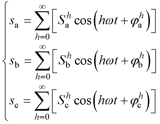 (1)
(1)
 、
、 、
、 为三相实信号;
 为谐波次数;
 、
、 、
、 为三相信号第
 为基波角频率;
 、
、 、
、 为三相信号第
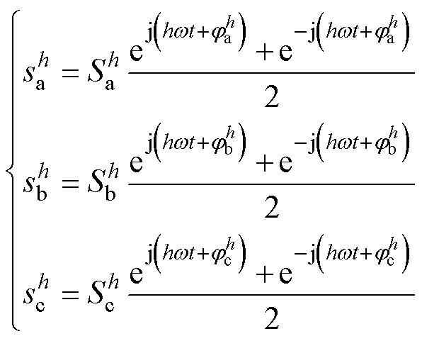 (2)
(2)
 (3)
(3) 为三相信号第h次谐波的幅值;
 为三相信号第h次谐波的相位;
 、
、 为可以构成三相信号第
 (4)
(4)
 和
和 。
。 次采样。根据香农采样定理,当采样信号大于有效信号最高频率的2倍时,采样值中包含原始信号的所有信息,被采样信号可以不失真地还原成原始信号。因此,能从采样信号中获得的最大频率分量为
 ,其中
,其中 为采样频率,
 ,
, (5)
(5)
 (6)
(6) 为时域信号
为时域信号 的采样值;
的采样值; 为第
为第 次谐波频率分量的DFT输出值。而第
 (7)
(7)
 为第
为第 (8)
(8)
 变换得到DFT谐波检测的
 域传递函数为
 (9)
(9)

 为第
为第 (复数)的
(复数)的 、复谐振器
、复谐振器 和增益系数
和增益系数 。
。
 (10)
(10)

 为输入序列为实数时的传递函数。
 之和表示,谐振器
 由第
由第 次谐波的复谐振器
 构成,梳状滤波器和增益系数不变。假设
 ,
, ,
, ,图2为
,图2为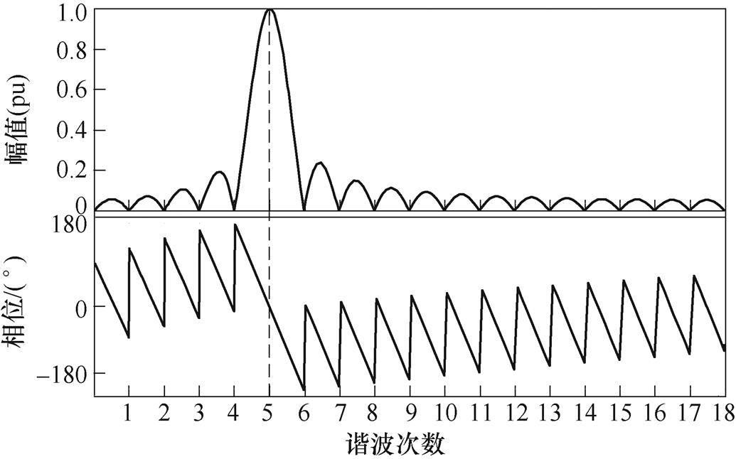
 的幅频响应曲线
 (11)
(11)
 、
、 、
、 为三相信号第
 、
、 (12)
(12)
 (13)
(13) (14)
(14)
 (15)
(15) ,在离散系统中,三相信号之间的关系为
 (16)
(16)
 (17)
(17) 为
为

 (18)
(18)

 (19)
(19) 变换得
变换得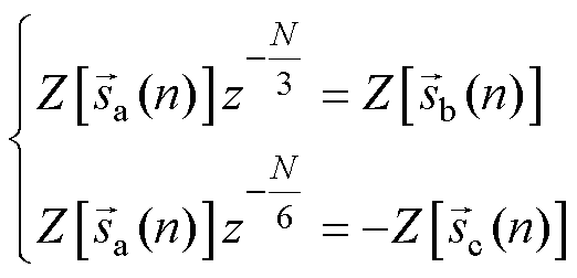 (20)
(20)
 (21)
(21)


 (22)
(22)
 为本文提出方法的等效传递函数;梳状滤波器为
 如式(22)所示,引入
 个零点以实现
 次谐波频率分量滤除,其中
 。而引入的
。而引入的
 的等效表达式
 中包含的梳状滤波器
 与求取的目标谐波频率分量的频率
 相关,即目标频率不同,滤波器
 (23)
(23)
 。式(23)表明,当求取的目标频率
 由
由 、
、 和
和 中的两个串联而成,而上述三个梳状滤波器引入
 个零点以分别实现
 、
、 和
和 次谐波频率分量滤除。因此,等效梳状滤波器
 个零点,产生1/3个基波周期的延迟。在本文提出的方法中,梳状滤波器
 中,是由B、C两相数据替换A相数据在频域中的表达,因此不产生实际的延迟。而整个检测过程的延迟都是由梳状滤波器
 实现
实现
 (24)
(24) (25)
(25)
 为输入序列为实数时本文提出方法的传递函数。
 次谐波信号。用SDFT进行谐波检测的仿真波形如图4所示。当三相不控整流电路投入运行时,产生畸变的电流,基波正序和5次负序分量在经过20ms的波动后进入稳态。在0.04s时,负载由30

 、
、 、
、 分别为A相负载电流、谐波参考电流、电网电流。图7a和图7b分别展示了采用SDFT和本文提出的方法的实验波形的动态过程。图8展示了负载突变时两种检测方法对应的实验波形。以上实验结果表明,SDFT和本文提出的方法都能实现特定次谐波检测,但是本文提出的方法比SDFT具有更好的动态响应过程且需要更少的存储空间。
 分别由23.56%降至0.64%和0.77%。
 时间段内的并网电流作FFT分析,实验结果如图11所示,表明采用本文提出方法的APF表现出更好的动态性能,但是因为实验过程中存在采样误差,导致达到稳态时并网电流的谐波含量偏高
 次谐波频率分量检测的
 域传递函数的推导
 可由两个共轭复信号表示为
 (A1)
(A1)

 (A2)
(A2)
 。
。
 (A3)
(A3) (A4)
(A4)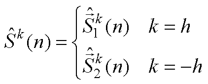 (A5)
(A5)
 次谐波信号在时域的表达式为
 (A6)
(A6)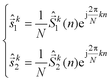 (A7)
(A7)
 次实信号应为在
 和
和 两处输出信号之和。因此实信号完整的第
 (A8)
(A8)
 (A9)
(A9)
 (A10)
(A10)
 (A11)
(A11)

 (A12)
(A12)

 (A13)
(A13)