 ;根据霍尔效应,放置于磁环气隙内的霍尔元件受该磁通量作用,将在霍尔元件两端产生正比于磁感应强度B的电动势差EHall,再经放大电路,输出正比于电流信号的电压信号Uout,即
摘要 可靠、精确的电流检测是三相桥式逆变电路控制和保护策略的关键。针对三相桥式逆变电路电流检测问题,该文首先分析霍尔、磁通门和分流器三种电流传感器的工作原理,比较三者检测特性及优缺点。然后从高端电流检测、低端电流检测和复合电流检测三个方面对多电流传感器方法进行的综述分析;从脉宽调制波形调整、电压矢量合成和状态观测三个方面对直流母线单电流传感器电流检测方法进行分析;从中间桥臂耦合、上下桥臂耦合和多支路耦合三个方面对多位置耦合电流检测方法进行分析;从固有误差和采样误差两个方面对电流检测误差的产生机理及解决方法进行分析。最后对三相桥式逆变电路以及相关电力电子电路变换器电流检测方法的发展趋势进行展望。
关键词:电流检测 电流传感器 直流母线采样 多位置耦合 检测误差
作为典型的电力电子电路拓扑结构,三相桥式逆变电路广泛应用于交流电机驱动、并网逆变器等电力电子装置。电流检测主要用来为三相桥式逆变电路的控制策略、保护策略提供电流参数,如何可靠、精确地获取电流信息是实现逆变电路高效、高性能运行的关键[1-4]。
在三相桥式逆变电路中,需要对高频波动的直流母线或三相负载电流瞬时值进行检测,其检测结果用来为电流、磁链的闭环控制提供反馈值,或者为开关器件、负载的过电流保护提供参考。
目前,电流检测传感元件主要包括霍尔电流传感器、磁通门电流传感器和分流器。常见的电流检测方法包括:①使用两个或三个电流传感器在负载的高端(交流输出侧)进行电流检测;②使用两个或三个电流传感器在低端(下桥臂)检测;③使用单电流传感器在直流母线上进行电流检测;④使用单霍尔/磁通门电流传感器采用多位置耦合方式进行电流检测。
伴随着电力电子高频化发展趋势,以及逆变器性能、可靠性要求的提升,目前三相桥式逆变电路电流检测面临的主要挑战包括:①如何提升全量程电流检测精度,尤其是小电流的检测精度,以提升电机低速、低转矩下的控制精度,或者确保并网逆变器在弱光、低风速下的可靠工作;②如何消除多个电流传感器参数不一致性造成的测量误差,以提升逆变器的控制精度;③如何通过优化电流传感器安装位置、开发新型PWM方法,以确保单电流传感器能够为控制策略提供完备的电流反馈信息; ④如何在多应用背景下,针对不同误差类型,开发消除直接检测误差和间接导致误差的融合性方法,是提升电流检测精度面临的重大挑战。
针对三相桥式逆变电路电流检测问题,本文从传感器工作原理及特性、多传感器安装位置、单传感器电流检测系统的基本工作原理和实现方法、多位置耦合电流检测方法的电流耦合路径以及电流检测误差的产生机理和消除方法等方面入手,对现有三相桥式逆变电路电流检测方法进行了综述分析,并对其发展进行了展望。
霍尔电流传感器的基本工作原理为霍尔效应,可实现直流电流、交流电流的隔离检测,根据其结构和磁通测量方式,可分为开环式霍尔电流传感器和闭环式霍尔电流传感器[5]。
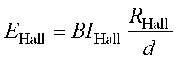
开环霍尔电流传感器结构如图1所示,开环式霍尔电流传感器由霍尔元件、磁心以及放大电路三部分组成。当被测电流流经放置于测量孔位的导线时,在环形磁心内产生与电流强度成正比的磁通量 ;根据霍尔效应,放置于磁环气隙内的霍尔元件受该磁通量作用,将在霍尔元件两端产生正比于磁感应强度B的电动势差EHall,再经放大电路,输出正比于电流信号的电压信号Uout,即
 (1)
(1)
式中,B为磁感应强度,B= ,S为磁环气隙截面积;IHall为霍尔激励电流;RHall为霍尔系数;d为霍尔元件厚度。
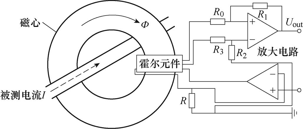
图1 开环霍尔电流传感器结构
Fig.1 Structure of open-loop Hall current sensor
开环霍尔电流传感器的特性:①结构简单、可靠性好、过载能力强;②由如图2所示的软磁材料磁滞曲线可知,随着磁场强度H的增加,磁感应强度B呈现非线性变化,导致线性度较差;③动态响应特性较差、频带宽度窄。
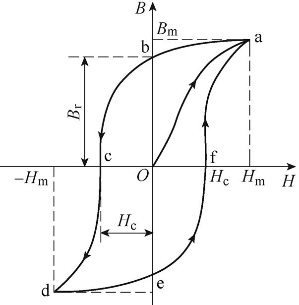
图2 典型软磁材料磁滞曲线
Fig.2 Hysteresis curves of typical soft magnetic materials
由上述分析可知,磁心的B-H曲线非线性特性是导致开环霍尔电流传感器线性度较差的主要因素。闭环霍尔电流传感器通过引入零磁通法,有效地提升了测量精度,属于磁平衡电流传感器,由磁心、霍尔元件、放大电路和二次线圈四部分组成,其结构如图3所示。测量原理为:被测电流流经放置于测量孔位的导线时,在环形磁心内产生磁通量 ,二次线圈产生大小相等、方向相反的磁通
 ,此时霍尔元件内部为零磁通。对于直流或者低频交流,反向磁通
 过小,磁通量
 和
和 无法完全抵消,根据霍尔元件检测到剩余磁通量
 ,闭环控制电路立刻调整补偿电流以维持零磁通状态,通过检测二次线圈电流Is即可实现电流测量。
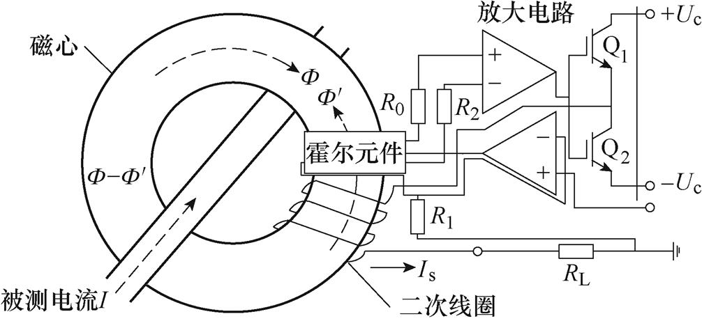
图3 闭环霍尔电流传感器结构
Fig.3 Structure of closed-loop Hall current sensor
闭环霍尔电流传感器特性:①磁心处于零磁通状态,消除了磁心的B-H非线性特性影响,具有良好的线性度;②霍尔元件仅用来测量剩余磁通量 ,有效提升了测量精度;③高频交流由二次线圈直接进行磁通抵消,低频或直流由闭环控制系统进行磁通抵消,因此具有较高的测量带宽。
对于磁平衡式电流传感器,剩余磁通量 的高灵敏度检测是确保其电流测量精度的基础。但是,受限于霍尔元件的低磁灵敏度和高温度漂移,闭环式霍尔电流传感器的测量精度和稳定性有待进一步提升[6-7]。
磁通门传感器是利用铁磁体在磁饱和区时的磁导率非线性特性实现磁场测量的一种装置。它具有高灵敏度、良好的温度稳定性,适用于微弱磁场的检测。在如图3所示闭环霍尔电流传感器结构的基础上,由磁通门传感器代替霍尔元件进行剩余磁通量检测便可构成磁通门电流传感器。
磁通门传感器由磁心、励磁电路、励磁绕组、检测绕组和信号处理电路等组成,如图4所示。当励磁电路输出角频率为w 的正弦励磁电流ie=I0sin(wt)时,产生的励磁磁场强度为He=N1I0sin(wt),N1为励磁绕组匝数。当磁心饱和时,其磁导率m 随着He周期性变化。由于m 为标量,其变化周期为He的一半,
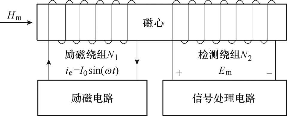
图4 磁通门传感器结构
Fig.4 Structure of fluxgate sensor
故其频率为2w,可描述为
 (2)
(2)
式中, 为磁导率直流分量;
 为各次谐波幅值。当被测磁场强度Hm=0时,检测绕组两端电动势为

 (3)
(3)
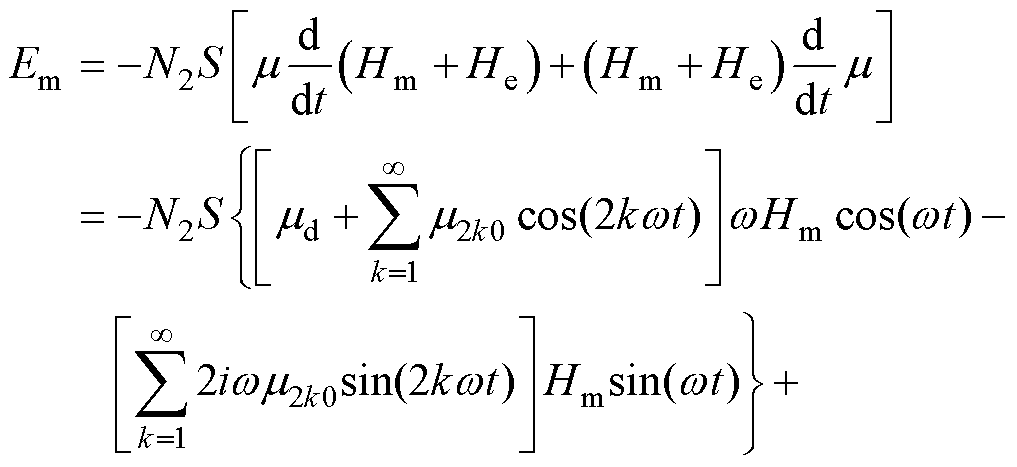
式中,H0=N1I0;A为磁心截面积。对式(3)进行分解,其仅包含励磁磁场强度He的奇次谐波。当被测磁场Hm≠0时,检测绕组两端电动势为
 (4)
(4)
由式(4)可知,当被测磁场强度Hm≠0时,检测绕组两端电动势中出现了幅值与被测磁场强度Hm成正比的偶次谐波。信号处理电路提取感应电动势的特定偶次谐波分量的幅值,便可得出被测磁场强度。
得益于磁通门传感器较高的灵敏度和良好的温度稳定性,磁通门电流传感器的精度和稳定性较闭环霍尔电流传感器有了显著提升。此外,磁通门电流传感器可采用整体磁心结构,消除气隙、漏磁以及安装位置偏差对剩余磁通量检测的影响。但是,由于励磁信号的存在,其输出信号的噪声较霍尔电流传感器大。
分流器本质是一个低值电阻,当被测电流流经分流器时,其两端产生与被测电流成正比的电位差,通过对该电位差的隔离、放大,便可实现交直流电流测量。
典型分流器电流测量电路由分流器、前端放大电路、差分隔离电路和信号调理电路四部分构成,如图5所示。前端放大电路一般采用同相差分输入方式,在放大分流器输出微弱差分信号的同时,以单位增益通过共模电压,提升了检测电路的信噪比和共模电压抑制比(Common-Mode rejection Ratio, CMR);差分隔离电路主要用于将前端放大电路输出的差分信号转化为单端信号并进行隔离;信号调理电路主要用于将差分隔离电路输出的信号进行偏置、放大等调理,以匹配后端的A-D转换电路[8-9]。
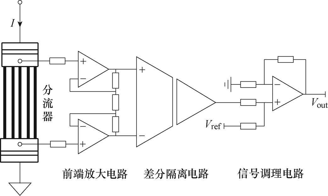
图5 典型分流器电流测量电路
Fig.5 Typical shunt current measurement circuit
一方面,由于大电流流经分流器时,会产生额外的热量,分流器额定阻值应适当降低;另一方面,分流器阻值过低会造成低电流测量时两端电位差过低,进而影响测量精度。因此,分流器阻值的选取应综合考虑高电流时的热损耗和低电流时的电位 差[9-10]。工程中,一般选取由锰铜、康铜或者镍铬合金等低温度系数材料制成的精密电阻,阻值一般为100mW 至数mW[9]。
由于温度是影响分流器测量精度和稳定性的重要因素,目前关于分流器电流测量的研究主要集中于消除不同材料结合点处热电动势对测量精度的影响,以及如何通过数据分析修正温度对测量精度的影响[10-13]。
除分流器的温度特性之外,影响分流器电流测量电路性能的关键因素还包括分流器的分布电感、信号处理电路的静态和动态性能等。在小量程电流检测时,分流器测量电路具有精度高、响应速度快、线性度好等优点。
三相桥式逆变电路中,通常采用三个电流传感器来实现相电流的检测。此外,根据KCL定律,仅通过测量两相电流,也可计算出第三相电流。根据多电流传感器的安装位置,可分为高端电流检测、低端电流检测和复合电流检测。
两电流传感器高端检测电路如图6所示,采用高端电流检测时,电流传感器安装于ABC三相的输出端,可采用霍尔、磁通门和分流器等传感器形式。其优点在于:①可采用两电流传感器,完全替代三电流传感器;②被测电流与开关状态无关,可在任意时刻实现电流采样;③当采用分流器时,采用差分信号处理方式可避免地电平噪声干扰。
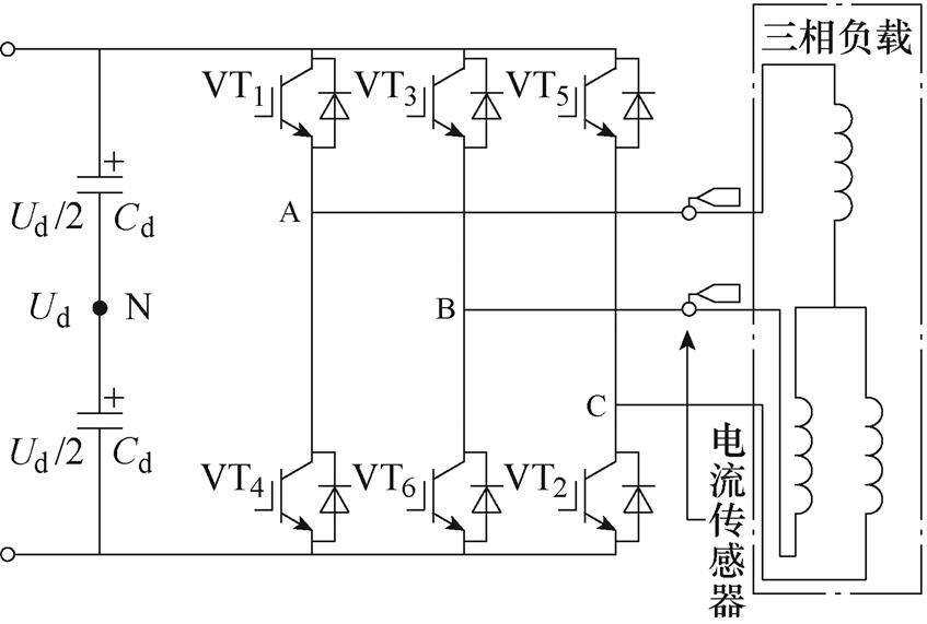
图6 两电流传感器高端检测电路
Fig.6 High-end detection circuit of two current sensors
主要缺点在于:①采用分流器时,需要采用隔离放大电路或采用高共模电压差分放大器,信号处理电路复杂;②由于信号处理电路中元件较多,温度变化、元器件参数差异将引入额外误差,同时,电路的动态性能受运放压摆率等参数的限制。
两电流传感器低端检测电路如图7所示,采用低端电流检测方法时,电流传感器安装于逆变器的下桥臂,同样可采用霍尔、磁通门和分流器等传感器形式[14-16]。
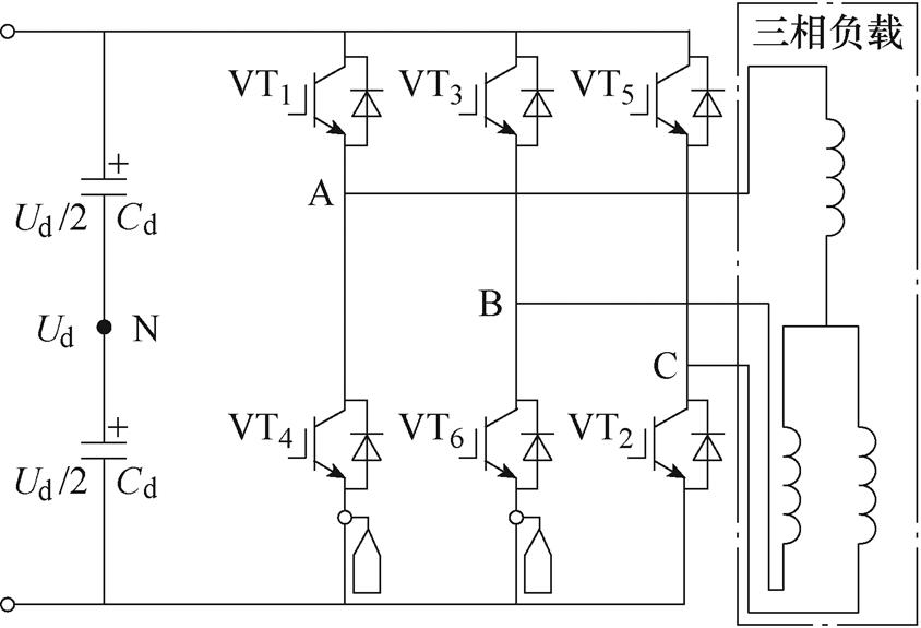
图7 两电流传感器低端检测电路
Fig.7 Low-end detection circuit of two current sensors
定义上桥臂导通用1表示,下桥臂导通用0表示。当下桥臂全部导通(000)时,由于三相感应负载的存在,电流传感器将检测到续流电流存在,续流回路如图8所示。
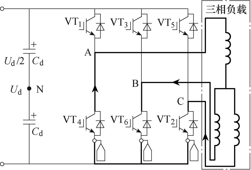
图8 V0(000)作用时续流回路
Fig.8 Freewheeling circuit when V0(000) is activated
低端电流检测方法可采用两电流传感器或者三电流传感器,两种方法主要区别为:①由于低端采样仅在(000)状态存在检测窗口,当某一相0状态作用时间过短时,只能采用压摆率更高的运算放大器或带宽更高的霍尔/磁通门电流传感器;②当采用三电流传感器时,可通过选择0状态作用时间较长的两相进行测量,并根据KCL定律计算出第三相电流。低端采样时序如图9所示,C相0状态作用时间过短,可仅通过AB两相电流的采样值,计算出C相电流,上述过程也称为“跳跃检测”。
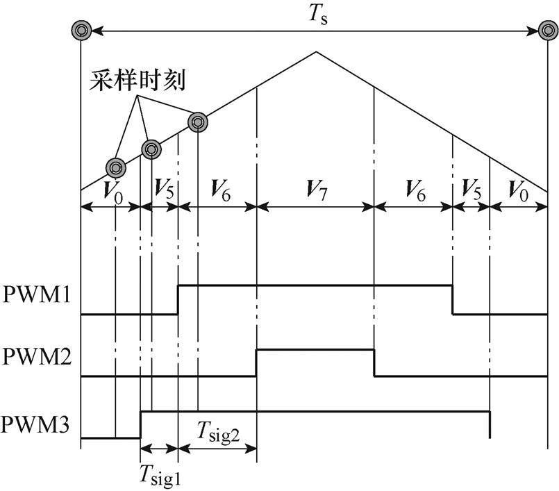
图9 低端采样时序
Fig.9 Low-end sampling timing
低端电流检测的主要优点在于:①采用分流器时,信号共模电压低,可使用低成本普通运算放大器实现高精度电流检测;②实现了续流电流测量,为单电流传感器多位置耦合电流测量奠定了基础。
其主要缺点在于:①测量时刻受开关状态制约;②采用分流器时,测量信号易受地电平噪声干扰;③随着频率进一步升高,电流测量窗口逐渐缩短,电流传感器及其信号处理电路必须有足够高的带宽。
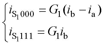
考虑高低端电流检测的优势互补,复合电流检测系统结构及电流路径如图10所示。霍尔/磁通门电流传感器安装于低端检测位置同时耦合高端电流回路。当V7(111)作用时续流回路如图10a所示,电流传感器S1流经B相电流;当V0(000)作用时续流回路如图10b所示,电流传感器流过的电流为B、A两相电流之差。电流传感器S1的电流检测值为
 (5)
(5)
式中,G1为增益;ia、ib分别为A、B两相电流。
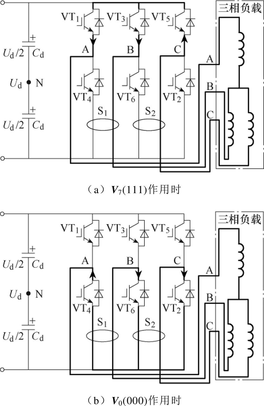
图10 复合电流检测系统结构及电流路径
Fig.10 Structure and current path of composite current detection system
由式(5)可知,复合电流检测采用单一霍尔/磁通门电流传感器消除了高端/低端电流检测多个传感器参数不一致的缺点。该电路结构中电流传感器S1和电流传感器S2可组合获得更多电流信息,实现差分式补偿零点漂移[17]。复合电流检测方法的主要缺点在于使用两个霍尔/磁通门电流传感器成本高,且无法消除由传感器不一致性带来的测量 误差。
综上所述,三种多传感器电流检测方法的对比分析见表1。
表1 三种多传感器电流检测方法的对比分析
Tab.1 Comparison among three multi-sensors current detection methods

检测方法传感器数量优点缺点 高端检测2/3使用率最高的检测方法,安全性、容错性高,适用于重型器械控制中如起重机、电梯等与单传感器电流检测相比成本更高,易受传感器精度影响,维修、更换成本高 低端检测2/3可使用低成本运算放大器实现高精度电流检测,能完成续流电流的测量可靠性降低,受开关状态影响大 复合检测2可获得的电流信息更多,可进行误差抑制电路拓扑复杂
单电流传感器电流检测技术主要分为直流母线单电流传感器检测和多位置耦合电流检测方法两大类。其中,前者又可细分为PWM波形调整方法、电压矢量合成方法和状态观测法,后者可细分为中间桥臂耦合、上下桥臂耦合和多支路耦合电流检测方法,单电流传感器控制技术分类如图11所示。
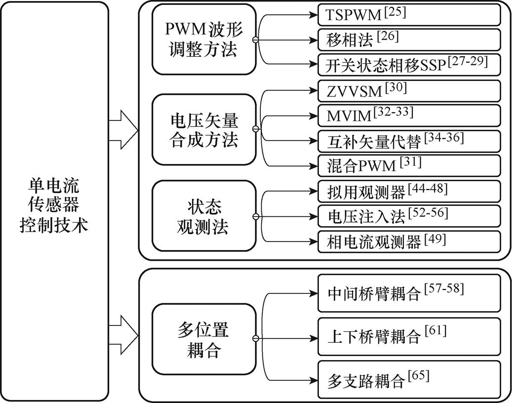
图11 单电流传感器控制技术分类
Fig.11 Classification of single current sensor control technologies
空间矢量脉宽调制(Space Vector Pulse Width Modulation, SVPWM)方式下,三相两电平逆变器存在八种基本开关状态,构成了PWM逆变器的八种基本电压矢量,分别为6个基本非零矢量V1(100)、V2(110)、V3(010)、V4(011)、V5(001)、V6(101)和2个零矢量V0(000)、V7(111)。SVPWM的空间电压矢量如图12所示,6个非零矢量将复平面空间分为如图12所示的6个扇区[18-24]。
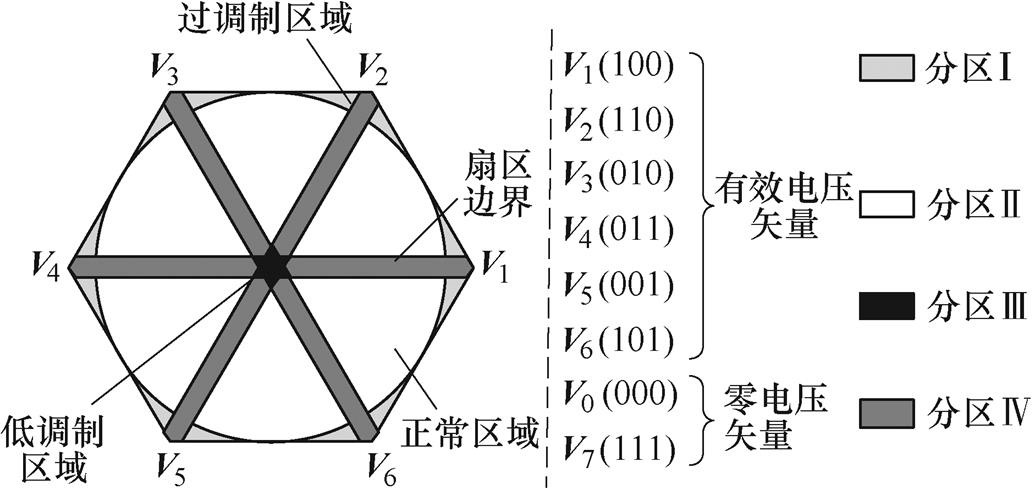
图12 SVPWM的空间电压矢量
Fig.12 Space vector of SVPWM
根据三相两电平逆变器的电路原理以及SVPWM的工作原理,通过将电流传感器安装在直流母线上,在不同的基本电压矢量作用下直流母线电流与电机的相电流的关系不同,可以分析得到不同开关状态时母线电流与绕组相电流的对应关系,见表2。
表2 电压矢量与绕组相电流的对应关系
Tab.2 Correspondence between voltage vector and winding phase current

电压矢量母线电流 V1(100)ia V2(110)-ic V3(010)ib V4(011)-ia V5(001)ic V6(101)-ib V0(000)0 V7(111)0
定义系数Xi(i=1, 2, 3),Xi=1表示上桥臂开关导通,Xi=0表示下桥臂开关导通,因此可以得到相电流与母线电流的关系[20],即
 (6)
(6)
在实际直流母线采样中,必须结合开关器件的实际特性,为电流检测单元提供可靠的时间窗口Tsig,定义最小采样时间Tmin[24]为
 (7)
(7)
式中,Tes为直流母线电流建立时间;Tdb为三相逆变电路的死区时间;Trise为导通后电流上升所需要的时间;Tsr为电流波动后需要稳定的时间;Tcon为数模转换器A-D的工作时间。
当满足式(8)时,PWM占空比接近,开关状态维持时间太短,无法进行可靠的电流采样,故该区域称为不可观测区域,包括低、过调制区域和扇区边界,如图12所示。
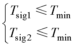 (8)
(8)
为实现不可观测区域内的电流采样,直流母线单电流传感器检测方法可分为三类。
1)PWM波形调整方法
文献[25]使用三个相邻的开关状态构成参考电压,提出了三态脉宽调制(Three-State Pulse Width Modulation, TSPWM)方法,在缩小了不可观测区域的同时减小了共模电压。文献[26]通过移动PWM而产生满足最小采样时间的电流检测窗口,实现了不可观测区域内的电流检测。文献[27-29]提出了开关状态相移(SSPS)相电流重构方法,扩大了电流检测窗口。调整PWM波形将导致传统SVPWM的对称性消失,从而改变输出电流纹波,进而影响三相电流总谐波畸变率(Total Harmonic Distortion, THD),不同方法对THD的影响如图13所示。
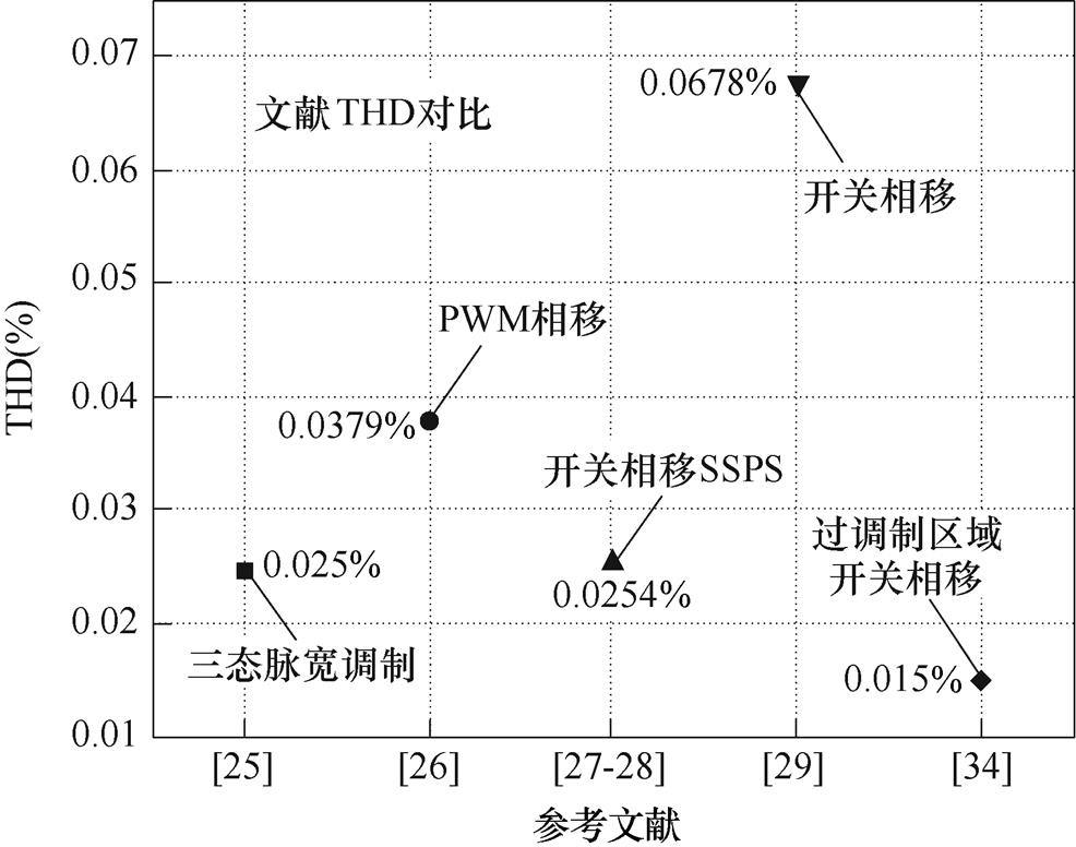
图13 文献THD总结
Fig.13 Summary of literature THD
2)电压矢量合成方法
文献[30]采用零电压矢量采样方法(Zero Voltage Vector Sampling Method, ZVVSM)时检测电流,实现了不可观测区域内电流的检测,但并未考虑零电压矢量检测导致的电流谐波问题。文献[31]提出了基于传统SVPWM和互补非零矢量的混合脉宽调制策略,在保证可观测区域低电流畸变的情况下,实现了不可观测区域内的电流检测。文献[32-33]针对有效电压矢量持续时间过短的问题,提出了插入测量矢量法(Measurement Vector Insertion Method, MVIM)相电流重构。文献[34]使用互补有效矢量代替零矢量,解决了低速状态下的电流重构问题。文献[35]在过调制区域内通过电流叠加降低了电流重构误差,与传统的SVPWM相比THD降低12%(从15%到3%)。文献[36]对6个扇区内的不可观测区域进行再次划分,提出了混合脉宽调制策略,消除了不可观测区域。文献[37-41]把单电流传感器技术引入到了多电平应用中。文献[42]在三电平中点钳位型(Neutral Point Clamped, NPC)逆变器中使用单电流传感器重构三相电流,通过电压补偿扩大了不可观测区域。文献[43]针对三电平逆变器,提出了基于移相法的电流重构策略,扩大了不可观测区域。电压矢量合成方法对比见表3。
表3 电压矢量合成方法对比
Tab.3 Comparison of voltage vector synthesis methods

文献方法开关损耗 [30]ZVVSM不增加开关次数 [32-33]MVIM单相插入增加2次开关次数 [31, 34]互补有效矢量代替零矢量增加4次开关次数
3)状态观测法
针对在PWM载波顶部或底部的重构电流和测量电流之间存在差异的问题,文献[44]提出了电流预测方法,降低了电流纹波和电机转矩波动。文献[45]针对三相永磁同步电机(Permanent Magnet Synchronous Motor, PMSM)控制器的相电流重构问题,利用正弦曲线拟合观测器,从母线电流中提取相电流信息,从而对电机进行矢量控制。文献[46]通过设计电流观测器,利用单相电阻估算三相电流,提出了一种新型单电阻电流重构技术。文献[47]提出了基于电机abc三相坐标系的电流状态观测器方法,通过计算不同矢量作用下瞬时电流变化率来分步预测电流,进而实现不可观测区域内的相电流重构。文献[29, 48]提出了在消除不可观测区域的同时,能够补偿采样延迟的预测状态观测器方法。文献[49]提出了基于三个独立自适应相电流观测器的单传感器相电流重构方法,即使在低调制度下也能保证精确的相电流估计。针对相电流重构中存在的采样不同步问题,文献[50]提出了拉格朗日插值法相电流预测方法,仿真证明了其可行性。文献[51]分析了由单电流传感器引起的分时采样误差,提出了基于电机简化数学模型的补偿方法,提高了电流重构精度。在确保满足最小采样时间前提下,文献[52-56]使用电压注入方法提高了重构精度。状态观测主要包括观测器法、预测状态观测器法和电压注入法,三种方法的对比见表4。
表4 状态观测方法对比
Tab.4 Comparison of state observer methods

文献方法缺点优点 [44-46]观测器算法复杂,可靠性低可有效消除不可观测区域,可有效提高重构精度 [29, 48, 51]预测状态观察器运算量大,依赖于模型精度消除不可观测区域的同时考虑了采样延迟误差、比例和增益误差等 [52-56]电压注入电压注入过程如不能保证与参考矢量之间的精度,将带来更大测量误差考虑了死区时间、不对称PWM等引起的电流纹波问题
多位置耦合方式利用单霍尔/磁通门电流传感器,可实现多支路分时电流测量,通过重新设计传感器电流传输路径,实现了单电流传感器电流检测。根据传感器安装位置和电流耦合方式,多位置耦合电流检测方法可分为中间桥臂耦合方式(Inter- mediate Bridge Arm Coupling, IBAC)、上下桥臂耦合方式(Upper-Lower Bridge Arm Coupling, ULBAC)和多支路耦合方式(Multi-Position Coupling, MPC)。
1)中间桥臂耦合方式
分析参考电压矢量PWM周期构成可发现,有效矢量作用时间过短的情况下,零矢量V0(000)、V7(111)作用时间增加,故可通过在零矢量工作时,分析电流与传感器位置之间的关系,以实现低调制区域内的电流测量。
中间桥臂耦合单霍尔/磁通门电流检测电路及电流路径如图14所示,单霍尔/磁通门传感器中流经A相中间桥臂和B相输出电流[57-58]。在零矢量V7(111)作用时,相电流通过上桥臂、二极管和绕组续流,此时电流导通情况如图14a所示(箭头表示续流通路)。此时单霍尔/磁通门电流传感器采样电流ismp为
 (9)
(9)
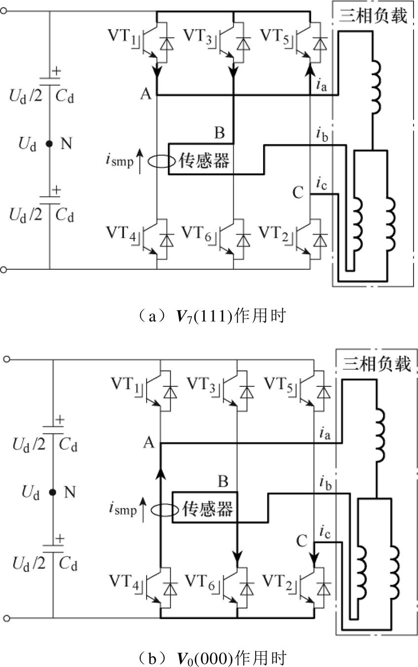
图14 中间桥臂耦合单霍尔/磁通门电流检测电路及电流路径
Fig.14 Structure and current path of IBAC single Hall/fluxgate current detection circuit
在零矢量V0(000)作用时,相电流通过下桥臂、二极管和负载续流,电流导通情况如图14b所示。此时单霍尔/磁通门电流传感器采集电流信息为
 (10)
(10)
结合KCL可知,ia+ib=-ic,故
 (11)
(11)
图15所示为中间桥臂单霍尔/磁通门电流传感器电流检测时序,图中,t1和t2为采样时刻,DA、DB、DC为载波时刻,Sa~Sc为开关状态。不同开关状态时电压矢量与绕组相电流对应关系见表5,由于零矢量电流可测[59-60],可采用4个可测量电流窗口中不同的两个电流值来完成相电流重构,完成低调制区向空间矢量六边形边界移动。
2)上下桥臂耦合方式
由于位置耦合的灵活性,单霍尔/磁通门电流传感器还可采用如图16所示的上下桥臂耦合方式[61]。传感器安装在下桥臂VT2、VT4之间的干路上,同时耦合了VT1、VT3之间线路。若单霍尔/磁通门电流传感器仅位于VT2、VT4之间干路时,将只能获得Vn(XX0)(X=0或1)作用时的电流测量值,一共有V1(100)、V2(110)、V3(010)、V0(000)四种情况可完成电流测量[50-55],同时存在着更大的不可观测区域。而耦合VT1、VT3之间线路,可在完成有效矢量测量的同时,实现零矢量V7(111)的检测。零矢量V7(111)作用时,上桥臂导通,导通路径如图16a所示,由于续流原因,零矢量V0(000)作用时,下桥臂导通,导通路径如图16b所示。
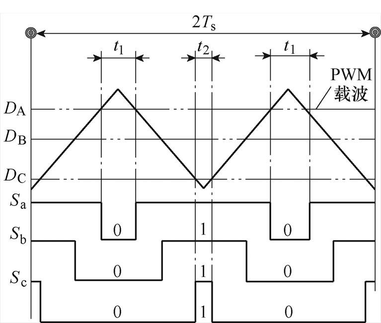
图15 中间桥臂耦合单霍尔/磁通门电流采样时序
Fig.15 Sampling timing of intermediate bridge arm coupling single Hall/fluxgate current detect circuit
表5 IBAC电压矢量与绕组相电流的对应关系
Tab.5 Correspondence between voltage vector and winding phase current for IBAC

电压矢量母线电流 V1(100)-ib V2(110)ib V3(010)-ic V4(011)-ic V5(001)ia-ib V6(101)-ib V0(000)-ic V7(111)-ib
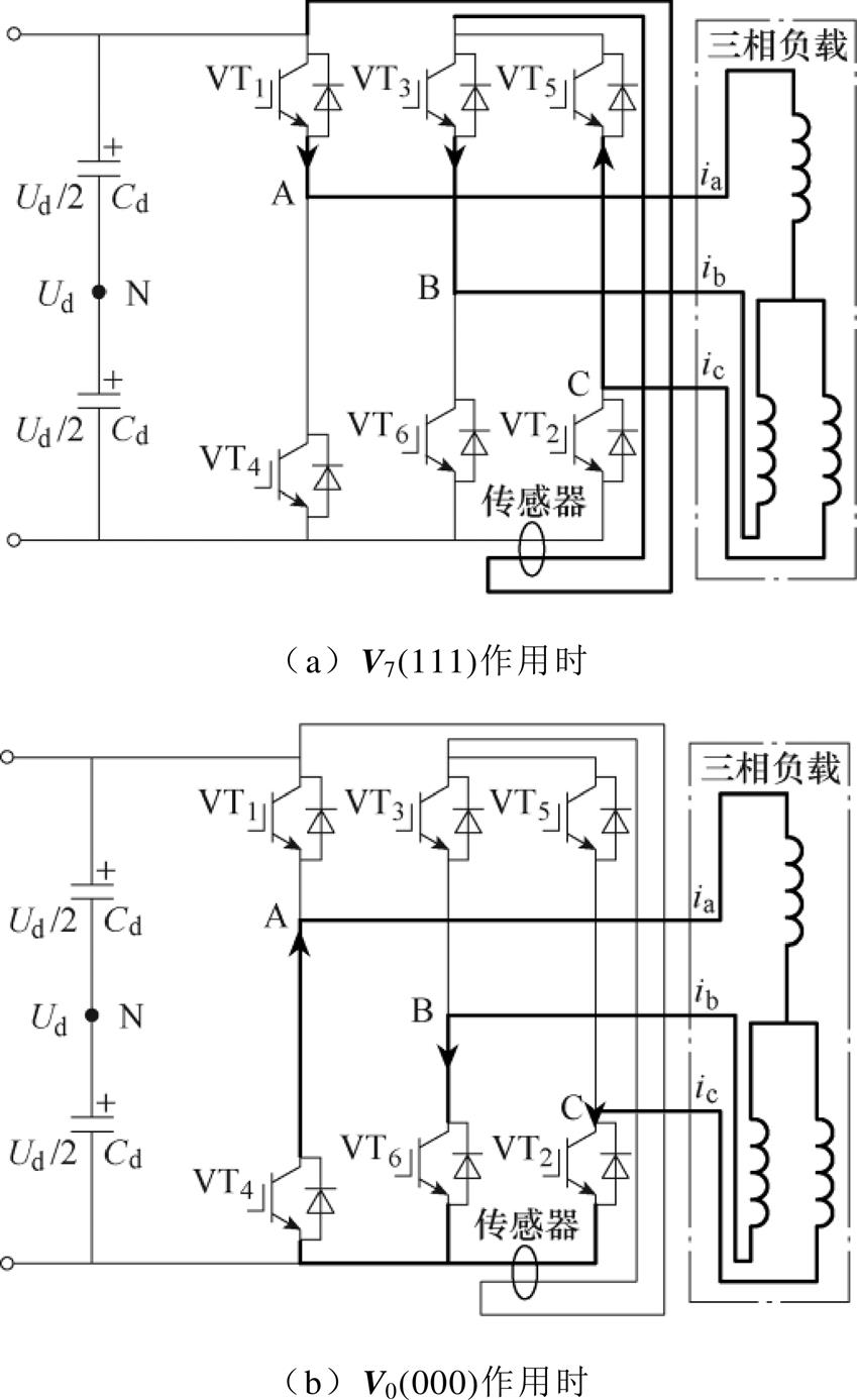
图16 上下桥臂耦合单霍尔/磁通门电流检测电路及电流路径
Fig.16 Structure and current path of ULBAC single Hall/fluxgate current detection circuit
 (12)
(12)
 (13)
(13)
ULBAC电压矢量与绕组相电流的对应关系见表6。由表6可知,与传统单传感器直流母线相电流检测方法相比,ULBAC方法在保持原有电流检测窗口的同时,增加了零矢量电流检测窗口,相电流重构策略更灵活[62-64]。
表6 ULBAC电压矢量与绕组相电流的对应关系
Tab.6 Correspondence between voltage vector and winding phase current for ULBAC

电压矢量母线电流 V1(100)0 V2(110)ib V3(010)ib V4(011)-ia V5(001)ic V6(101)ic V0(000)ic V7(111)-ia
3)多支路耦合方式
上述两种耦合方式增加了不可观测区域的电流检测窗口,其缺点为在零矢量作用时段内进行电流采样的同时也会造成正常区域内有效矢量无法测量。文献[65]创新性地提出了如图17所示的多位置耦合单霍尔/磁通门电流传感器安装位置,可同时完成有效矢量和零矢量作用时段内的电流检测。
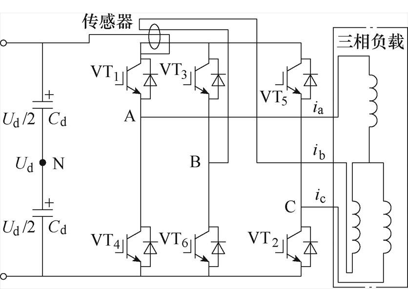
图17 多位置耦合单霍尔/磁通门电流传感器安装位置
Fig.17 Installation position of single Hall/fluxgate sensor for MPC
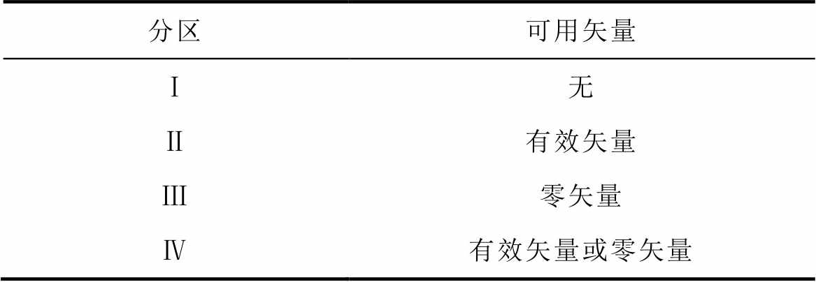
文献[65]对矢量扇区内存在不可观测区域的原因进行了分析,为兼顾有效矢量和零矢量电流检测,可得出测量位置与测量电流、分区与可用于检测的矢量之间的关系,分别见表7和表8。
表7 MPC分区与可用矢量关系
Tab.7 Correspondence between sector and available vector for MPC
分区可用矢量 Ⅰ无 Ⅱ有效矢量 Ⅲ零矢量 Ⅳ有效矢量或零矢量
表8 MPC测量位置与测量电流的关系
Tab.8 Correspondence between measuring position and current for MPC

测量位置测量电流 1i1=X1ia+X2ib+X3ic 2i2=X2ib+X3ic 3i3=X3ic 4i4=ia 5i5=ib 6i6=ic 7i7=ib(1-X2)+ic(1-X3) 8i8=ic(1-X3)
如图17所示的多支路耦合方式,融入了多个传感器测量位置,同时探索了位置耦合与电流之间的对应关系,既可以完成传统SVPWM可观测区域的有效矢量的测量,又可以测量零矢量,从而扩展了电流的可观测区域。但是,由表7和表8可知,找到可确保每个分区内都能检测到电流的共同矢量,是实现多位置耦合电流检测的关键[65]。
IBAC、ULBAC和MPC三种方法的耦合支路数量、重构误差及关键特征见表9。
表9 多位置耦合电流检测方法对比
Tab.9 Comparison of three multi-position coupled current detection methods

耦合方式耦合支路重构误差/A关键特征 IBAC2≤0.21实现电流重构的同时还可消除漂移误差 ULBAC20.7~0.9使用有效矢量代替零矢量,提高了电流重构精度 MPC3≤0.2可进行多电流检测,具有较高灵活性
电流传感器在长期使用时或恶劣工作条件下,电流检测精度将受到影响[66]。两种主要电流检测误差如图18所示,在电流采样过程中存在两种类型的误差:一种是由于PWM引起的固有误差;另一种是由于温度或老化等因素造成的传感器采样误差。两种误差在不加校正的情况下会直接引入到测量电流中。
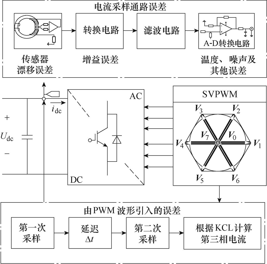
图18 两种主要电流检测误差
Fig.18 Two main current detection errors
空间矢量作用时瞬时相电压、平均相电流以及ia、ic相的电流纹波如图19所示。由PWM引起的固有误差分为分时误差、非齐误差和切换误差。
1)分时误差
当矢量V1(100)作用时完成第一次采样得到电流ia,经过Dt,第二次采样在矢量V2(110)作用时完成得到采样电流-ic,两个采样点之间的延迟造成的误差为分时误差。第一次采样值与最终值相差Dierr1,如图19所示,最终采样结果为
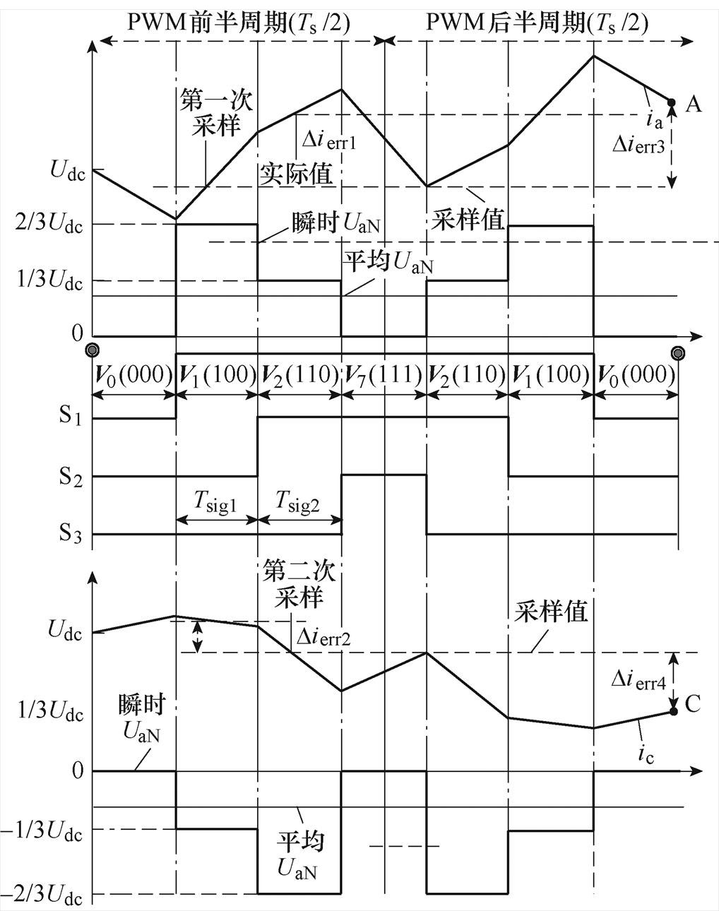
图19 分时采样误差
Fig.19 Time-sharing sampling error
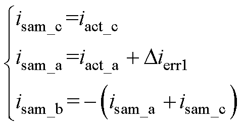 (14)
(14)
针对分时误差,文献[67]提出了回溯预测电流校正方法,在七段式电流中引入PWM周期等效电流概念,并通过观测器计算等效电流变化率和瞬时电流变化率以预测PWM周期结束时A、C点的三相电流值。文献[68]提出了基于 参考系的补偿方法,利用
 轴和
轴和 轴误差分量存在的比例关系消除分时误差。
2)非齐误差
直流母线电流采样点分别在零电压矢量V0(000)、V7(111)作用时完成测量,即PWM载波的顶部或底部,而实际位于V1(100)、V2(110)作用时段内,采样结果与最终值非对齐的采样位置导致重构误差为Dierr3和Dierr4。
针对该问题,文献[69]提出了基于内置式永磁同步电动机(Interior Permanent Magnet Synchronous Motor, IPMSM)的电压模型预测参考电压采样点的dq电流重构方法,最大限度地减少了重构误差。
3)切换误差
互补矢量代替零矢量SVPWM可以消除不可观测区域,扇区过渡如图20所示[70],但不适用于扇区切换时刻。以第Ⅰ和Ⅵ扇区为例,采样位置为每个载波的顶端,在PWM周期2内能获得采样电流ib和ic。参考电压矢量进入扇区Ⅰ时受Tmin影响,PWM周期3处只采样得到ib一相电流,叠加前周期采样结果进行电流重构,导致产生切换误差。
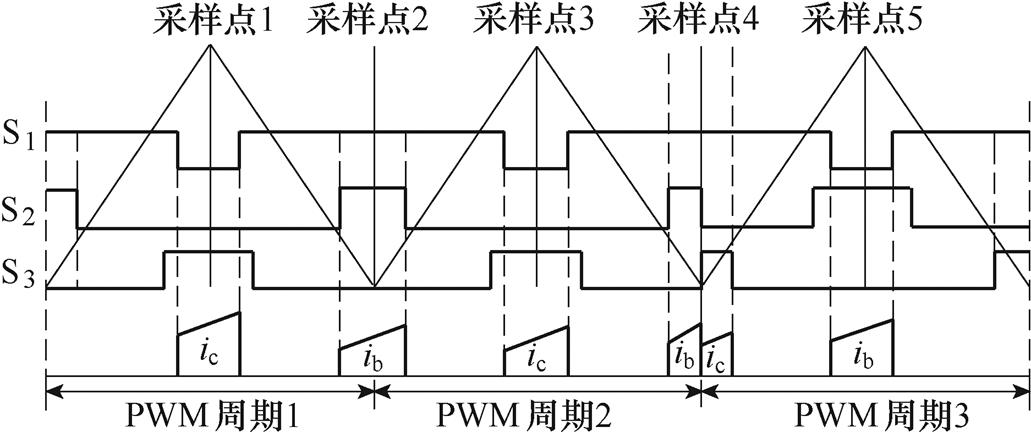
图20 扇区过渡
Fig.20 Sector transition
文献[70]提出了分离电流预测校正方法,在未切换时刻使用传统相电流重构策略,在扇区切换时刻根据预测的dq电流和可测量电流来计算实际三相电流,消除了切换误差。
4.2.1 采样分析
采样通路由霍尔传感器、转换电路、滤波电路和数模(A-D)转换电路等构成[71],如图18所示。受器件容差、温度漂移、老化和噪声等影响,电流采样通路中将产生漂移误差和增益误差。
由漂移误差导致的采样结果为
 (15)
(15)
 (16)
(16)
 (17)
(17)
式中,isam_b、isam_c为采样电流;ire_b、ire_c为实际电流;Did为电流零点漂移误差,根据KCL计算第三相电流。不同扇区的最终电流采样结果分析见表10。
根据式(15)~式(17),同步旋转坐标系下的 轴电流分别为
 (18)
(18)
表10 最终电流采样结果
Tab.10 Final current sampling result

扇区isam_aisam_bisam_c Ⅰire_a+Didire_bire_a+ire_b+Did Ⅱire_aire_b+Didire_a+ire_b+Did Ⅲire_b+ire_c+Didire_b+Didire_c Ⅳire_b+ire_c+Didire_bire_c+Did Ⅴire_aire_a+ire_c+Didire_c+Did Ⅵire_a+Didire_a+ire_c+Didire_c
式中, 为
为 轴实际电流分量;
 为漂移分量。可知,重构
 轴电流中不包含电流漂
移分量。在同步旋转坐标系中,abc轴电流在转换为dq轴电流时,最终零点漂移被带进dq轴电流中。
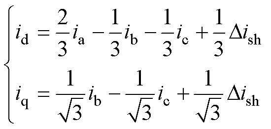 (19)
(19)
同理,考虑增益误差
 (20)
(20)
式中, 、
、
 分别为采样电流和实际电流;Kg
为电流增益误差,即
 (21)
(21)
式中,KN(N=A, B, C)为每相电流增益,KN =KKn,n=a, b, c,K为相同增益误差,Kn为相增益误差[72]。
4.2.2 误差校正
文献[73]提出了由电流增益引起的不平衡直流漂移和负序分量误差在线校正方法,通过估计q轴转子磁通与实际转子磁通误差,对负序分量进行校正,消除了参数不匹配导致的估计误差。由式(18)可知,b 轴中存在漂移误差,利用直流分量不会突变这一特性,使用陷波器可以阻碍或衰减特定频率的信号。文献[74]提出了如图21所示的电流漂移在线校正控制策略,通过PI控制器校正估计的电流漂移量,实现了三相电流的重构。零点漂移和增益误差引起的电压误差具有独特的频率特性,文献[75]假设d轴和q轴电流的时间导数忽略不计,通过从PI控制器的输出中减去电阻的压降来估算电压误差。文献[76]提出了一种电流测量误差补偿方案,基于直流输出电压纹波特性和带通/低通滤波器消除了电流漂移和增益误差。文献[77]对比了陷波器和低通滤波器,提出了静止参考系中带有滤波器的电流漂移补偿方法。零点漂移和增益误差也会导致速度纹波、转矩脉动和三相电流不平衡[78],针对该问题,文献[79]提出了使用单电流传感器的位置传感器故障检测策略,通过将相反矢量设置在一个PWM周期内,在一个周期内进行双采样获得电流平均值以校正转子估计位置估计值,该方法可以减少采样误差,但不能区分漂移量是由漂移误差还是瞬态电流引起的[80]。
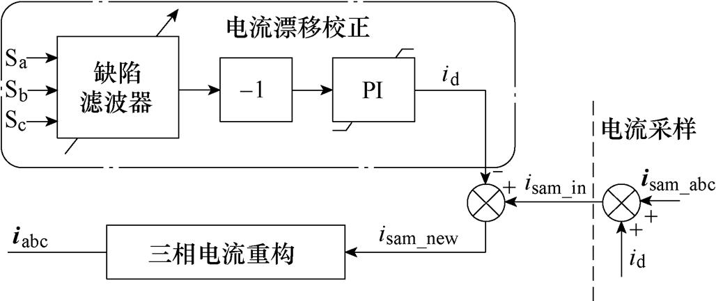
图21 误差类型及解决方案
Fig.21 Error types and solutions
为降低电机驱动系统成本,有学者使用低成本ADC,其电路中只包含一到两个采样保持(S/H)器。由于S/H器数量不足而导致的异步采样会带来电流测量误差[81]。文献[82]通过关闭逆变器的C相桥臂使A相桥臂和B相桥臂流出电流的矢量和为零,若B相出现增益误差,则使用A相正常电流补偿B相误差,使两者幅值保持一致,实现了增益误差的离线补偿。
由于逆变器应用于电动汽车、微电网以及新能源并网等多种场合,直流母线电压源通常由不可控整流器提供或由直流变换器直接供电[83],因此电压波动将导致转矩脉动和速度波动。文献[84]提出了基于低端支流和三相电流耦合的电流检测策略,并结合定点抽样方法,解决了速度波动。文献[85]针对永磁直线电机驱动器提出了双矢量定位模型预测控制(DL-MPC)方法,可降低相电流传感器电流检测误差。
在实际应用场景中,通常不确定两个交流侧电流传感器和直流母线的电流传感器的精度,导致维修或更换成本的增加[86-87]。针对多个传感器出现的不确定性问题,文献[88]提出了多电流传感器误差补偿策略,通过相互校准策略对电流漂移和增益误差进行补偿,实现了不依赖数字滤波器和电机参数的误差校准。文献[89]提出了基于三相电流检测的补偿方法,通过比较两相传感器和三相传感器检测到的dq轴电流,实现了增益误差检测。但如果电机停止或转子位置锁定,则无法使用该方法。针对转子锁定情况下的误差检测,文献[90]提出了基于两相测量电流四种组合的增益补偿方法。
综上所述,电流误差类型、针对对象及解决方案如图22所示。
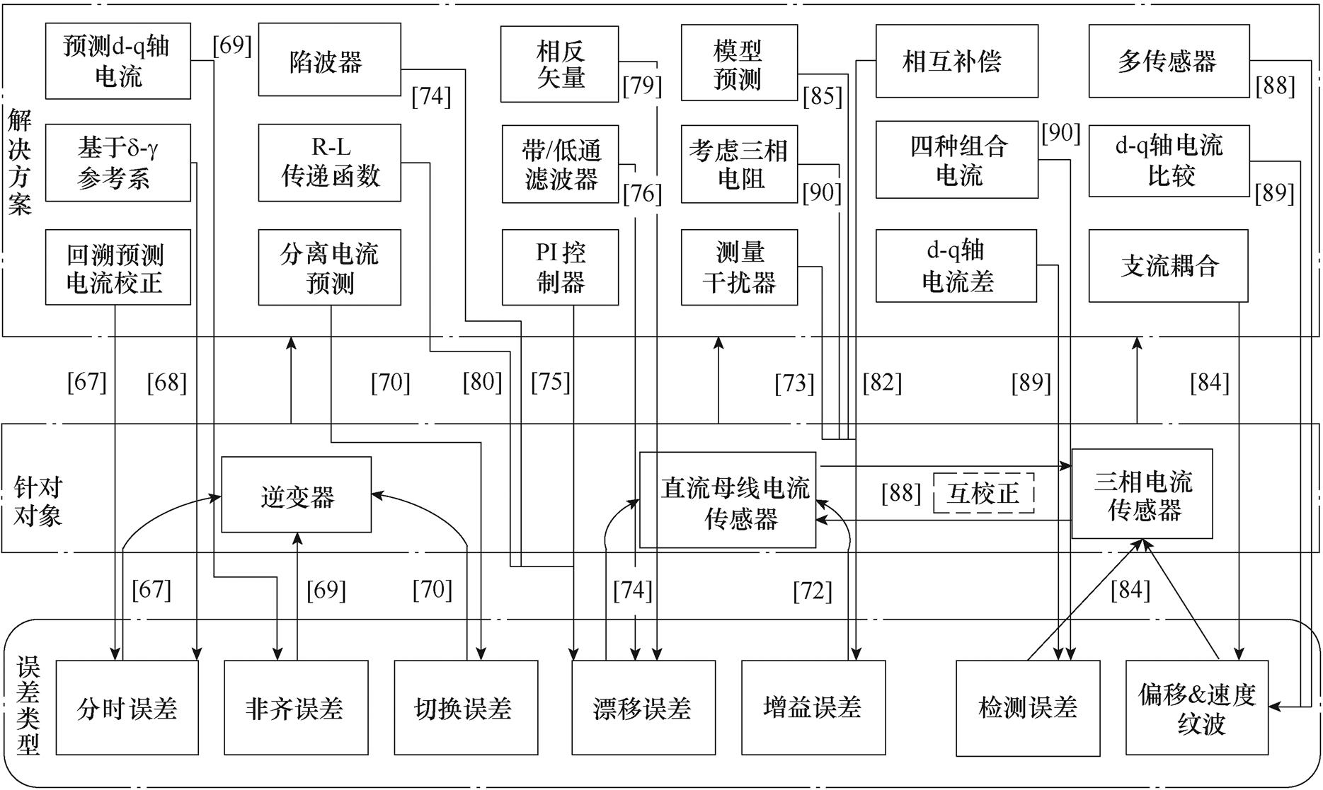
图22 电流误差分析
Fig.22 Analysis of current error
围绕三相桥式逆变电路的高可靠性、高集成度、高精度电流检测需求,研究人员已从传感器设计、PWM波形调整、矢量合成方法优化、电流状态观测、电流检测位置及电流耦合关系设计、电流检测误差的产生机理及解决方法等方面展开了深入研究,并取得了重要研究进展。但是,一方面伴随着SiC、GaN等宽禁带电力电子半导体器件的发展,电力电子高频化发展趋势越来越明显,扩大了单传感器电流检测的不可观测区域,对电流传感器及信号处理电路的响应速度、可靠性提出了新的挑战;另一方面,“双碳”战略目标下,交流电机驱动、并网逆变器等领域的高效、高性能控制需求也对电流检测系统的测量精度提出了新的要求。针对上述问题,对未来三相桥式逆变电路以及相关电力电子电路变换器的电流检测系统做如下展望。
1)高带宽、高响应速度电流传感器研究:目前工业应用领域,典型的闭环霍尔电流传感器带宽通常为100kHz(-3dB)左右,响应时间通常为1ms以内(90%额定电流);磁通门电流传感器带宽可达300kHz(-3dB),响应时间通常为0.5ms以内(90%额定电流)。面对开关频率可到数百kHz甚至MHz的宽禁带电力电子半导体器件,在某些高载波频率、复杂控制算法应用场景下,如何进一步提升带宽、降低响应时间对于快速、准确地实现电流传感,仍需要从磁场敏感元件、传感器结构和电路结构等方面进行深入研究。
2)单电流传感器最小采样时间的定量计算:最小采样时间的精确定量计算是开展单传感器采样的前提,受限于功率器件的导通特性、变换器死区设置、信号处理及A-D转换时间、调制度/载波周期等因素,当矢量作用时,电流需要经过第一阶段主要包含功率器件的导通特性及变换器死区设置,第二阶段主要包含由运放摆率、负载感抗造成的信号处理及A-D转换时间的动态过程,才能出现第三阶段的稳定状态。如何围绕上述五方面因素,结合矢量控制系统的调制度及载波周期,实现最小采样时间的精确定量计算,是提升低调制度、高载波频率下单电流传感器系统可靠应用的关键。
3)采样位置及耦合路径优化:对于多位置耦合电流检测方法,合理的采样位置和耦合路径,能够有效消除电流耦合,实现低调制度和扇区边界处的电流采样。目前已有的相关方法通过传感器耦合路径、脉宽调制策略的优化,一定程度上扩展了电流可观测区域。但是缺少对传感器安装位置及耦合路径之间电流关系的系统分析,同时缺少矢量合成方法与耦合路径之间的理论推导,限制了多位置耦合电流检测性能的进一步提升。通过采样位置及耦合路径优化,是扩展多位置耦合电流检测方法应用范围,实现低调制度和扇区边界处的电流采样的重点。
4)电流采样精度的研究:尽管单电流传感器方法在一定程度上消除了多传感器参数不一致带来的电流误差,但是由于仅采用一套电流传感器及信号处理电路,其零点漂移误差会扩大至所有相电流,进而影响重构精度。因此,进一步深入分析单电流传感器误差扩大效应的产生机理,通过优化采样位置及耦合路径、优化矢量合成方法、开发零点漂移校正策略等方法,消除误差扩大效应对电流重构的影响,实现零点漂移误差的自检测及自校正,是提升单电流传感器电流检测方法测量精度的关键。
参考文献
[1] 张懿, 张明明, 魏海峰, 等. 基于霍尔传感器的永磁同步电机高精度转子位置观测[J]. 电工技术学报, 2019, 34(22): 4642-4650.
Zhang Yi, Zhang Mingming, Wei Haifeng, et al. High precision rotor position observation of permanent magnet synchronous motor based on hall sensors[J]. Transactions of China Electrotechnical Society, 2019, 34(22): 4642-4650.
[2] 申永鹏, 郑竹风, 杨小亮, 等. 直流母线电流采样电压空间矢量脉冲宽度调制[J]. 电工技术学报, 2021, 36(8): 1617-1627.
Shen Yongpeng, Zheng Zhufeng, Yang Xiaoliang, et al. A compatible SVPWM method for DC bus current sampling[J]. Transactions of China Electrotechnical Society, 2021, 36(8): 1617-1627.
[3] 马铭遥, 凌峰, 孙雅蓉, 等. 三相电压型逆变器智能化故障诊断方法综述[J]. 中国电机工程学报, 2020, 40(23):7683-7698.
Ma Mingyao, Ling Feng, Sun Yarong, et al. Review of intelligent fault diagnosis methods for three-phase voltage-mode inverters[J]. Proceedings of the CSEE, 2020, 40(23): 7683-7698.
[4] 王文杰, 闫浩, 邹继斌, 等. 基于混合脉宽调制技术的永磁同步电机过调制区域相电流重构策略[J]. 中国电机工程学报, 2021, 41(17): 6050-6059.
Wang Wenjie, Yan Hao, Zou Jibin, et al. Phase current reconstruction strategy of PMSM under over- modulation mode based on a hybrid space vector pulse width modulation technique[J]. Proceedings of the CSEE, 2021, 41(17): 6050-6059.
[5] 李树成. 直流电流检测中霍尔传感器的应用[J]. 通信电源技术, 2017, 34(4): 240-241.
Li Shucheng. Application of hall sensor in DC current detection[J]. Telecom Power Technology, 2017, 34(4): 240-241.
[6] 刘海艳. 磁通门微电流传感器设计[J]. 自动化技术与应用, 2016, 35(9): 101-105.
Liu Haiyan. Design of micro-current sensor based on the fluxgate principle[J]. Techniques of Automation and Applications, 2016, 35(9): 101-105.
[7] 罗颖, 谢小军, 朱才溢, 等. 大电流检测技术探析[J]. 仪器仪表标准化与计量, 2020(3): 32-34.
Luo Ying, Xie Xiaojun, Zhu Caiyi, et al. Analysis of high current detection[J]. Instrument Standardization & Metrology, 2020(3): 32-34.
[8] 仪表放大器应用工程师指南(第三版)[EB/OL]. 美国模拟器件公司, 2013.
[9] Grundkötter E, Weßkamp P, Melbert J. Transient thermo-voltages on high-power shunt resistors[J]. IEEE Transactions on Instrumentation and Mea- surement, 2018, 67(2): 415-424.
[10] Braudaway D W. Behavior of resistors and shunts: with today's high-precision measurement capability and a century of materials experience, what can go wrong?[J]. IEEE Transactions on Instrumentation and Measurement, 1999, 48(5): 889-893.
[11] Braudaway D W. Precision resistors: a review of the techniques of measurement, advantages, disadvan- tages, and results[J]. IEEE Transactions on Instru- mentation and Measurement, 1999, 48(5): 884-888.
[12] Webkamp P, Haubmann P, Melbert J. 600-A test system for aging analysis of automotive Li-ion cells with high resolution and wide bandwidth[J]. IEEE Transactions on Instrumentation and Measurement, 2016, 65(7): 1651-1660.
[13] 郑锦秀, 童欣. 一元线性回归方程在大电流分流器测量中的应用[J]. 计测技术, 2009, 29(5): 17-19.
Zheng Jinxiu, Tong Xin. Application of unitary linear regression equation for measuring this great diffluent utensil[J]. Metrology & Measurement Technology, 2009, 29(5): 17-19.
[14] 费继友, 梁晟铭, 李花, 等. 基于双电阻的变频控制器交流电流采样方法研究[J]. 大连交通大学学报, 2017, 38(6): 103-106.
Fei Jiyou, Liang Shengming, Li Hua, et al. Research of sampling AC current with double resistance based on variable frequency controller[J]. Journal of Dalian Jiaotong University, 2017, 38(6): 103-106.
[15] 王文, 罗安, 黎燕, 等. 一种新型有源电力滤波器的SVPWM算法[J]. 中国电机工程学报, 2012, 32(18): 52-58, 177.
Wang Wen, Luo An, Li Yan, et al. A novel algorithm of SVPWM applied to active power filters[J]. Pro- ceedings of the CSEE, 2012, 32(18): 52-58, 177.
[16] 王平, 厉虹, 王道武. 小容量变频器三电阻采样电流合成方法实现[J]. 电气自动化, 2014, 36(1): 64-66, 93.
Wang Ping, Li Hong, Wang Daowu, et al. How to synthesize 3-resistor sampling current for the small- capacity converter[J]. Electrical Automation, 2014, 36(1): 64-66, 93.
[17] 邓娜. 基于改进相电流重构的电流采样校正方法[J]. 电气传动, 2020, 50(8): 15-20.
Deng Na. Current sampling correction method based on improved phase current reconstruction[J]. Electric Drive, 2020, 50(8): 15-20.
[18] 储剑波, 胡育文, 黄文新, 等. 一种变频器相电流采样重构技术[J]. 电工技术学报, 2010, 25(1): 111- 117.
Chu Jianbo, Hu Yuwen, Huang Wenxin, et al. Phase current sampling reconstruction for inverter[J]. Transactions of China Electrotechnical Society, 2010, 25(1): 111-117.
[19] 赵辉, 胡仁杰. SVPWM的基本原理与应用仿真[J]. 电工技术学报, 2015, 30(14): 350-353.
Zhao Hui, Hu Renjie. Space-vector pulse width modulation and it's simulation based on Simulink[J]. Transactions of China Electrotechnical Society, 2015, 30(14): 350-353.
[20] 王凯, 王之赟, 宗兆伦, 等. 基于霍尔位置传感器的永磁同步电机速度估计方法研究[J]. 电机与控制学报, 2019, 23(7): 46-52.
Wang Kai, Wang Zhiyun, Zong Zhaolun, et al. Speed estimation method of permanent magnet synchronous motor based on Hall-effect sensor[J]. Electric Machines and Control, 2019, 23(7): 46-52.
[21] 朱强, 王进城, 孙荣川. 逆变器基于电阻采样的直流分量调节电路分析[J]. 电力电子技术, 2018, 52(1): 92-93, 107.
Zhu Qiang, Wang Jincheng, Sun Rongchuan. DC component regulating circuit analysis of inverter based on resistance sampling[J]. Power Electronics, 2018, 52(1): 92-93, 107.
[22] 马建辉, 高佳, 周广旭, 等. 一种SVPWM简化算法的设计与实现[J/OL]. 电源学报, 2020, 1-12[2020- 11-02]. https://kns.cnki.net/kcms/detail/12.1420.tm. 20201030.1629.004.html.
Ma Jianhui, Gao Jia, Zhou Guangxu, et al. Design and implement of a simplified SVPWM algorithm[J/OL]. Journal of Power Supply, 2020, 1-12[2020-11-02]. https://kns.cnki.net/kcms/detail/12.1420.tm.20201030. 1629.004.html.
[23] 王帆, 陈阳生. 不同PWM模式下交流电机单电阻三相电流采样的研究[J]. 机电工程, 2013, 30(5): 585-590, 631.
Wang Fan, Chen Yangsheng. Research on phase current reconstruction for AC motor based on different PWM mode[J]. Journal of Mechanical & Electrical Engineering, 2013, 30(5): 585-590, 631.
[24] Shen Yongpeng, Zheng Zhufeng, Wang Qiancheng, et al. DC bus current sensed space vector pulse width modulation for three-phase inverter[J]. IEEE Transa- ctions on Transportation Electrification, 2021, 7(2): 815-824.
[25] Lu Haifeng, Cheng Xiaomeng, Qu Wenlong, et al. A three-phase current reconstruction technique using single DC current sensor based on TSPWM[J]. IEEE Transa- ctions on Power Electronics, 2014, 29(3): 1542-1550.
[26] Yang S C. Initial rotor position estimation of permanent- magnet synchronous machines using square-wave voltage injection with a single current sensor[C]// Applied Power Electronics Conference & Exposition, Fort Worth, TX, USA, 2014: 2430-2437.
[27] Gu Yikun, Ni Fenglei, Yang Dapeng, et al. Switching- state phase shift method for three-phase-current reconstruction with a single DC-link current sensor[J]. IEEE Transactions on Industrial Electronics, 2011, 58(11): 5186-5194.
[28] Blaabjerg F, Pedersen J K. An ideal PWM-VSI inverter using only one current sensor in the DC- link[C]//International Conference on Power Elec- tronics & Variable-speed Drives, IET, London, UK, 1994: 458-464.
[29] Lee W C, Lee T K, Hyun D S. Comparison of single- sensor current control in the DC link for three-phase voltage-source PWM converters[J]. IEEE Transa- ctions on Industrial Electronics, 2001, 48(3): 491- 505.
[30] Xu Yongxiang, Yan Hao, Zou Jibin, et al. Zero voltage vector sampling method for PMSM three- phase current reconstruction using single current sensor[J]. IEEE Transactions on Power Electronics, 2017, 32(5): 3797-3807.
[31] Lai Y S, Lin Yongkai, Chen C W. New hybrid pulsewidth modulation technique to reduce current distortion and extend current reconstruction range for a three-phase inverter using only DC-link sensor[J]. IEEE Transactions on Power Electronics, 2013, 28(3): 1331-1337.
[32] Kim H, Jahns T M, Integration of the measurement vector insertion method (MVIM) with discontinuous PWM for enhanced single current sensor oper- ation[C]//IEEE Industry Applications Conference Forty-First IAS Annual Meeting, Tampa, FL, USA, 2006: 2459-2465.
[33] Kim H, Jahns T M. Phase current reconstruction for AC motor drives using a DC link single current sensor and measurement voltage vectors[C]//36th Power Electronics Specialists conference, 2005: 1413-1419.
[34] Dusmez S, Qin Ling, Akin B. A new SVPWM technique for DC negative rail current sensing at low speeds[J]. IEEE Transactions on Industrial Elec- tronics, 2015, 62(2): 826-831.
[35] Sun Kai, Wei Qing, Huang Lipei, et al. An over- modulation method for PWM-inverter-fed IPMSM drive with single current sensor[J]. IEEE Transactions on Industrial Electronics, 2010, 57(10): 3395-3404.
[36] Lu Jiadong, Zhang Xiaokang, Hu Yihua, et al. Inde- pendent phase current reconstruction strategy for IPMSM sensorless control without using null switching states[J]. IEEE Transactions on Industrial Electronics, 2018, 65(6): 4492-4502.
[37] Ye Haizhong, Emadi A. A six-phase current recon- struction scheme for dual traction inverters in hybrid electric vehicles with a single DC-link current sensor[J]. IEEE Transactions on Vehicular Tech- nology, 2014, 63(7): 3085-3093.
[38] Cho Y, Koran A, Miwa H, et al. An active current reconstruction and balancing strategy with DC-link current sensing for a multi-phase coupled-inductor converter[J]. IEEE Transactions on Power Electronics, 2012, 27(4): 1697-1705.
[39] Li Xiong, Dusmez S, Akin B, et al. A new SVPWM for the phase current reconstruction of three-phase three-level t-type converters[C]//IEEE Applied Power Electronics Conference and Exposition (APEC), Charlotte, USA, 2015: 1582-1588.
[40] Shin H, Ha J I. Phase current reconstructions from DC-link currents in three-phase three-level PWM inverters[J]. IEEE Transactions on Power Electronics, 2014, 29(2): 582-593.
[41] Han J, Song J H. Phase current-balance control using DC-link current sensor for multiphase converters with discontinuous current mode considered[J]. IEEE Transactions on Industrial Electronics, 2016, 63(7): 4020-4030.
[42] Kim S, Ha J I, Sul S K. Single shunt current sensing technique in three-level PWM inverter[J]. 8th Inter- national Conference on Power Electronics-ECCE Asia, Jeju, Korea, 2011: 1445-1451.
[43] Kovačevic H, Korošec L, Milanovič M. Single-shunt three-phase current measurement for a three-level inverter using a modified space-vector modulation[J]. Electronics, 2021, 10(14): 1734.
[44] Ha J I. Current prediction in vector-controlled PWM inverters using single DC-link current sensor[J]. IEEE Transactions on Industrial Electronics, 2010, 57(2): 716-726.
[45] Saritha B, Janakiraman P A. Sinusoidal three-phase current reconstruction and control using a DC-link current sensor and a curve-fitting observer[J]. IEEE Transactions on Industrial Electronics, 2007, 54(5): 2657-2664.
[46] Zhao Jing, Nalakath S, Emadi A. Observer assisted current reconstruction method with single DC-link current sensor for sensorless control of interior permanent magnet synchronous machines[C]//IECON 2019-45th Annual Conference of the IEEE Industrial Electronics Society. IEEE, Lisbon, Portugal, 2019: 1228-1233.
[47] Lu Jiadong, Hu Yihua, Liu Jinglin. Analysis and compensation of sampling errors in TPFS IPMSM drives with single current sensor[J]. IEEE Transa- ctions on Industrial Electronics, 2019, 66(5): 3852- 3855.
[48] Cheng Xiaomeng, Lu Haifeng, Qu Wenlong, et al. Single current sensor operation with fixed sampling points using a common-mode voltage reduction PWM technique[C]//2009 IEEE 6th International Power Electronics and Motion Control Conference, Wuhan, China, 2009: 479-483.
[49] Wolbank T M, Macheiner P E. Current-controller with single DC link current measurement for inverter- fed AC machines based on an improved observer- structure[J]. IEEE Transactions on Power Electronics, 2004, 19(6): 1562-1567.
[50] Li Pengwei, Liao Yong, Lin Hao, et al. An improved three-phase current reconstruction strategy using single current sensor with current prediction[C]//2019 22nd International Conference on Electrical Machines and Systems (ICEMS), Harbin, China, 2019: 1-5.
[51] Marčetić D P, Adžić E M. Improved three-phase current reconstruction for induction motor drives with DC-link shunt[J]. IEEE Transactions on Industrial Electronics, 2010, 57(7): 2454-2462.
[52] Zhao Jing, Nalakath S, Emadi A. A high frequency injection technique with modified current recon- struction for low-speed sensorless control of IPMSMs with a single DC-link current sensor[J]. IEEE Access, 2019, 7(99): 136137-136147.
[53] Ha J I. Voltage injection method for three-phase current reconstruction in PWM inverters using a single sensor[J]. IEEE Transactions on Power Elec- tronics, 2009, 24(3): 767-775.
[54] Ryu H S, Yoo H S, Ha J I. Carrier-based signal injection method for harmonic suppression in PWM inverter using single DC-link current sensor[C]//Paris, France, 2006, 2700-2705.
[55] Lu Jiadong, Hu Yihua, Zhang Xiaokang, et al. High- frequency voltage injection sensorless control tech- nique for IPMSMs fed by a three-phase four-switch inverter with a single current sensor[J]. IEEE Transactions on Mechatronics, 2018, 23(2): 758-768.
[56] Gan Chun, Wu Jianhua, Yang Shiyou, et al. Phase current reconstruction of switched reluctance motors from DC-link current under double high-frequency pulses injection[J]. IEEE Transactions on Industrial Electronics, 2015, 62(5): 3265-3276.
[57] Yan Hao, Xu Yongxiang, Zhao Weiduo, et al. DC drift error mitigation method for three-phase current reconstruction with single hall current sensor[J]. IEEE Transactions on Magnetics, 2019, 55(2): 1-4.
[58] Yan Hao, Yang Jiacheng, Zeng Fangui, et al. New three-phase current reconstruction for PMSM drive with hybrid space vector pulse width modulation technique[J]. IEEE Transactions on Power Electronics, 2022, 37(12): 15209-15220.
[59] Shen Yongpeng, Wang Qiancheng, Liu Dongqi, et al. A mixed SVPWM technique for three-phase current reconstruction with single DC negative rail current sensor[J]. IEEE Transactions on Power Electronics, 2022, 37(5): 5357-5372.
[60] Metidji B, Taib N, Baghli L, et al. Phase currents reconstruction using a single current sensor of three- phase AC Motors fed by SVM-controlled direct matrix converters[J]. IEEE Transactions on Industrial Electronics, 2013, 60(12): 5497-5505.
[61] Cho Y, LaBella T, Lai J S. A three-phase current reconstruction strategy with online current offset compensation using a single current sensor[J]. IEEE transactions on industrial electronics, 2011, 59(7): 2924-2933.
[62] Cheng He, Mi Shuai, Wang Zelu, et al. Phase current reconstruction with dual-sensor for switched relu- ctance motor drive system[J]. IEEE Access, 2021, 9: 114095-114103.
[63] Sun Qingguo, Wu Jianhua, Gan Chun, et al. A new phase current reconstruction scheme for four-phase SRM drives using improved converter topology without voltage penalty[J]. IEEE Transactions on Industrial Electronics, 2018, 65(1): 133-144.
[64] Zhu Lianghong, Chen Feifan, Li Binxing, et al. Phase current reconstruction error suppression method for single DC-link shunt PMSM drives at low-speed region[J]. IEEE Transactions on Power Electronics, 2022, 37(6): 7067-7081.
[65] Tang Qipeng, Shen Anwen, Li Wuhua, et al. Multiple- positions-coupled sampling method for PMSM three- phase current reconstruction with a single current sensor[J]. IEEE Transactions on Power Electronics, 2020, 35(1): 699-708.
[66] Salmasi F R. A self-healing induction motor drive with model free sensor tampering and sensor fault detection, isolation, and compensation[J]. IEEE Transactions on Industrial Electronics, 2017, 64(8): 6105-6115.
[67] Wang Gaolin, Chen Feifan, Zhao Nannan, et al. Current reconstruction considering time-sharing sampling errors for single DC-link shunt motor drives[J]. IEEE Transactions on Power Electronics, 2021, 36(5): 5760-5770.
[68] Wang Wenjie, Yan Hao, Wang Xuejiao, et al. Analysis and compensation of sampling-delay error in single current sensor method for PMSM drives[J]. IEEE Transactions on Power Electronics, 2022, 37(5): 5918-5927.
[69] Im J H, Kim R Y. Improved saliency-based position sensorless control of interior permanent-magnet synchronous machines with single DC-link current sensor using current prediction method[J]. IEEE Transactions on Industrial Electronics, 2018, 65(7): 5335-5343.
[70] Wang Wenjie, Yan Hao, Xu Yongxiang, et al. Improved three-phase current reconstruction techni- que for PMSM drive with current prediction[J]. IEEE Transactions on Industrial Electronics, 2022, 69(4): 3449-3459.
[71] Song S H, Choi J W, Sul S K. Digitally controlled AC drives[J]. IEEE Ind. Appl. Mag, 2000, 6: 51-62.
[72] Yoo M S, Park S W, Lee H J, et al. Offline compensation method for current scaling gains in AC motor drive systems with three-phase current sensors[J]. IEEE Transactions on Industrial Elec- tronics, 2021, 68(6): 4760-4768.
[73] Cho K R, Seok J K. Correction on current measurement errors for accurate flux estimation of AC drives at low stator frequency[J]. IEEE Transa- ctions on Industry Applications, 2008, 44(2): 594- 603.
[74] Cho Y, LaBella T, Lai J S. A three-phase current reconstruction strategy with online current offset compensation using a single current sensor[J]. IEEE transactions on industrial electronics, 2011, 59(7): 2924-2933.
[75] Kim M, Sul S K, Lee J. Compensation of current measurement error for current-controlled PMSM drives[J]. IEEE Transactions on Industry Applications, 2014, 50(5): 3365-3373.
[76] Trinh Q N, Wang Peng, Tang Yi, et al. Compensation of DC offset and scaling errors in voltage and current measurements of three-phase AC/DC converters[J]. IEEE Transactions on Power Electronics, 2018, 33(6): 5401-5414.
[77] Hu Mingjin, Hua Wei, Wu Zheng, et al. Com- pensation of current measurement offset error for permanent magnet synchronous machines[J]. IEEE Transactions on Power Electronics, 2020, 35(10): 11119-11128.
[78] Jung H S, Hwang S H, Kim J M, et al. Diminution of current-measurement error for vector-controlled AC motor drives[J]. IEEE Transactions on Industry Applications, 2006, 42(5): 1249-1256.
[79] Lu Jiadong, Hu Yihua, Liu Jinglin, et al. Position sensor fault detection of IPMSM using single DC-bus current sensor with accuracy uncertainty[J]. IEEE Transactions on Mechatronics, 2019, 24(2): 753-762.
[80] Lee K W, Kim S J. Dynamic performance improve- ment of a current offset error compensator in current vector-controlled SPMSM drives[J]. IEEE Transa- ctions on Industrial Electronics, 2019, 66(9): 6727- 6736.
[81] Harke M C, Guerrero J M, Degner M W, et al. Current measurement gain tuning using high-frequency signal injection[J]. IEEE Transactions on Industry Appli- cations, 2008, 44(5): 1578-1586.
[82] Kim M S, Park D H, Lee W J. Compensation of current measurement errors due to sensor scale error and non-simultaneous sampling error for three-phase inverter applications[J]. Journal of Power Electronics, 2022, 22(1): 31-39.
[83] Liu Chunhua, Chau K T, Lee C H T, et al. A critical review of advanced electric machines and control strategies for electric vehicles[J]. Proceedings of the IEEE, 2021, 109(6): 1004-1028.
[84] Lu Jiadong, Hu Yihua, Liu Jinglin, et al. Fixed-point sampling strategy for estimation on current mea- surement errors in IPMSM drives[J]. IEEE Transa- ctions on Power Electronics, 2021, 36(5): 5748- 5759.
[85] Wang Wei, Lu Zhixiang, Tian Weijie, et al. Dual- vector located model predictive control with single DC-link current sensor for permanent-magnet linear motor drives[J]. IEEE Transactions on Power Elec- tronics, 2021, 36(12): 14142-14154.
[86] Hu, Yihua, Gan Chun, Cao Wenping, et al. Central- tapped node linked modular fault-tolerance topology for SRM applications[J]. IEEE Transactions on Power Electronics, 2016, 31(2): 1541-1554.
[87] Zhai Qiwei, Meng Ke, Dong Zhaoyang, et al. Modeling and analysis of lithium battery operations in spot and frequency regulation service markets in Australia electricity market[J]. IEEE Transactions on Industrial Informatics, 2017, 13(5): 2576-2586.
[88] Lu Jiadong, Hu Yihua, Chen Guipeng, et al. Mutual calibration of multiple current sensors with accuracy uncertainties in IPMSM drives for electric vehicles[J]. IEEE Transactions on Industrial Electronics, 2020, 67(1): 69-79.
[89] Harke M C, Lorenz R D. The spatial effect and compensation of current sensor differential gains for three-phase three-wire systems[J]. IEEE Transactions on Industry Applications, 2008, 44(4): 1181-1189.
[90] Yoo M S, Park S W, Choi Y Y, et al. Current-scaling gain compensation of motor drives under locked-rotor condition considering inequality of phase resi- stances[J]. IEEE Transactions on Industry Appli- cations, 2020, 56(5): 4915-4923.
Abstract As a typical power electronics topology, the three-phase bridge inverter circuit is widely used in motor driver, new energy grid-connected inverter, and other power electronic equipment. Current is an important parameter for the control and protection of inverter, how to obtain current information stably and accurately is the key to realize high-performance control of inverter. However, traditional control often overlooks fundamental, complex, and extensible problems caused by current parameters. Over recent years, many problems have been raised around the reliability of current detection and the improvement of accuracy, but most of the problems lack a closed-loop review of problem development. Aiming at these problems, this paper summarizes the related problems of current detection in three-phase bridge inverter, hoping to inspire follow-up research.
First of all, based on the principle analysis, the current sensors that are most widely used are summarized based on operating principle, sampling accuracy, advantages and disadvantages, including Hall current sensors, fluxgate current sensors, and shunts. Different current detection circuits are directly determined from the analysis of sensor installation characteristics and the number of uses, which are mainly divided into multi-sensor detection circuits and single-sensor detection circuits, and specifically including current sensing at the high-side (AC output side) of the load using two or three current sensors; current sensing on the low side using two or three current sensors; current sensing on the DC bus using a single current sensor; multi-position coupling for current sensing using a single Hall/fluxgate current sensor detection (intermediate bridge arm coupling (IBAC), upper-lower bridge arm coupling (ULBAC), and multi-position coupling (MPC)). This paper summarizes and analyzes the different current information, advantages, and disadvantages contained in the detection circuits at different positions.
However, in actual use, reliable and high-precision current sampling is caused by a combination of direct and indirect reasons. The direct reason includes long-term use of the point current sensor, or inaccurate measurement accuracy under harsh conditions. In the comprehensive use of the inverter, under different control algorithm strategies, the source (inherent error) of the current detection error occurs, so the research branch of the indirect cause of improving the current quality through PWM control strategy adjustment is derived. This paper summarizes and analyzes the influence of different control strategies such as the PWM waveform adjustment method, voltage vector synthesis method, and state observation method on the current in the case of a single current sensor, as well as the comparison of advantages and disadvantages.
Finally, this paper comprehensively analyzes the direct and indirect causes of current detection. There are two types of errors in the current sampling process: one is an inherent error due to PWM; the other is sensor sampling error due to factors such as temperature or aging. Both errors are directly introduced into the measured current without correction. The inherent errors caused by PWM are divided into time-sharing errors, non-homogenous errors, and switching errors. The sampling path is composed of a Hall sensor, a conversion circuit, a filter circuit, and an analog-to-digital (A-D) conversion circuit. Affected by device tolerance, temperature drift, aging, noise, etc., drift errors and gain errors will occur in the current sampling path. The two kinds of errors can be corrected by each other, and the suppression and compensation of sampling errors through control strategies is the current mainstream research branch of mutual errors.
In the future, there will still be major challenges in current detection: with the high frequency of power electronics, the research of current sensors with high bandwidth and high response speed is still an important branch; in the face of single current sensor sampling, the current sampling that is affected by multiple factors such as the optimization of the PWM strategy and the signal processing process should be considered comprehensively; for the research on the improvement of current accuracy, attention should be paid to the closed-loop relationship between the sensor itself and the control strategy, and at the same time, new background factors such as electromagnetic interference should be introduced from the foundation to improve the current detection accuracy.
Keywords:Current detection, current sensor, DC bus sampling, multi-position coupling, measurement errors
中图分类号:TM46
DOI: 10.19595/j.cnki.1000-6753.tces.220579
国家自然科学基金项目(62273313, 51807013, 52177068)、河南省科技攻关项目(222102240005)、河南省青年骨干教师培养计划项目(2021GGJS089)、郑州市协同创新专项(2021ZDPY0204)和河南省高校科技创新团队支持计划项目(22IRTSTHN017)资助。
收稿日期 2022-04-14
改稿日期 2022-05-17
E-mail: shenyongpeng@zzuli.edu.cn(通信作者)
刘 迪 男,1996年生,硕士研究生,研究方向为电动汽车动力系统驱动与控制。
E-mail: liudi_zzuli@163.com
(编辑 陈 诚)