图1 直流电能系统结构
Fig.1 Structure of DC electrical energy system
摘要 双三相永磁同步发电机(DTP-PMSG)具有容错率高、低压大功率等特点,适用于受输出电压、空间体积限制的高端装备领域。常规的母线电压控制方法在负载快速变化时,存在电压恢复时间长、电压波动大的缺点。该文提出基于交轴电流计算与电容储能反馈相结合的稳压控制策略。建立脉冲宽度调制(PWM)整流器能量和功率交换数学模型,推导交轴电流内环给定的计算表达式,设计电压外环并分析物理意义。该方法既能缩短电压恢复时间,又可以降低电压波动幅值。仿真和实验结果验证了所提控制策略的可行性和有效性。
关键词:交轴电流计算 电容储能反馈 电压波动 恢复时间 永磁同步发电机
随着特种车辆、军舰船舶和飞行器等高端装备的全电化发展,以发电机为核心的直流电能系统备受关注。因用电设备的工况复杂多变,对直流电能系统提出更高的要求[1-3]。受装备空间、输出电压、可靠性等约束,需要发电机具备低压大功率、容错率高等特性,多相永磁同步发电机成为选择[4-8]。
直流电能系统中的负载形式多样、工况复杂。从永磁同步发电机脉冲宽度调制(Pulse Width Modulation, PWM)整流稳压控制的角度,需要提出与负载功率突变相适应的控制策略[9-10]。降低直流侧母线电压波动幅值,加快母线电压恢复速度,为负载提供稳定可靠的直流电能,以确保系统的安全运行。目前,针对PWM整流器,已有方法多数是面对电力系统应用,如虚拟磁链定向控制[11]、直接功率控制等[12-14]。这些方法根据具体的电机对象,结合永磁同步电动机的控制方法[15-17],经过改进,也可适用于直流电能系统中永磁同步发电机的PWM整流控制。但外环仍以母线电压作为被控量的比例积分(Proportional Integral, PI)控制,不能满足高性能的母线电压控制需求。
文献[18]考虑到电压外环的物理意义,以直流侧电容储能作为反馈,构成电网侧整流器的外环,引入负载功率前馈估计,减小负载的不确定性对整流器系统的影响,提升系统的动态特性。但该方法需要多周期平均值估计负载功率,以此消除系统的采样误差,造成电压调节一定的滞后性。文献[19]提出改进的磁场定向控制策略,在传统的双闭环基础上,再引入新的电压反馈通道,直接与电压外环的输出转矩进行比较,将所得偏差作为电流内环给定,该方法能够加快转矩的瞬态响应速度,减小电压动态降落和恢复时间,但反馈系数、电压外环参数两者在设计时耦合,不利于快速整定。文献[20]基于速度的拓展状态观测器,替代传统的电压外环,将负载功率、开关损耗、参数变化等内外扰动作为扩张状态,实现电压外环的线性化处理。但拓展状态观测器内部各环节的设计较为复杂,存在较大的工作量。
本文主要以双三相永磁同步发电机(Dual Three-Phase Permanent Magnet Synchronous Generator, DTP- PMSG)为例进行分析,对永磁同步发电机构成的PWM整流系统的电压外环,提出一种简单有效的稳压控制策略。针对传统电压外环采用PI控制时响应速度慢、电压波动幅值大的问题,通过解析计算,直接得到交轴电流内环给定,有效地加快母线电压恢复,降低电压波动。考虑到实际系统存在损耗,造成简化的解析计算存在一定误差,利用电容储能反馈补偿,提升母线电压控制精度,实现直流母线电压的高性能稳压输出。
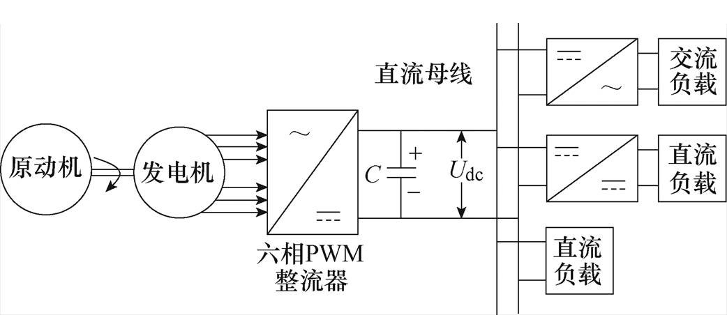
以DTP-PMSG为核心的直流电能系统结构如图1所示,系统由原动机、发电机、PWM整流器、直流母线电容、用电负载等基本单元构成。原动机与发电机轴连,拖动发电机机械旋转输出交流电能,通过控制整流器工作,将交流电能变换成直流电能,经直流母线电容滤波后,向多种负载供电。
图1 直流电能系统结构
Fig.1 Structure of DC electrical energy system
直流电能系统中,DTP-PMSG和六相电压型PWM整流器的基本结构如图2所示。DTP-PMSG定子绕组由两套中性点隔离、电角度互差30°的绕组ABC和DEF组成,整流器采用两电平结构与发电机绕组连接,易于数字控制的实现。图2中,Udc、idc分别为直流母线电压和负载电流,C、RL分别为直流母线电容和直流侧负载。
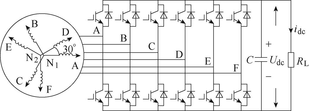
图2 DTP-PMSG PWM整流系统结构
Fig.2 Structure of DTP-PMSG PWM rectifier
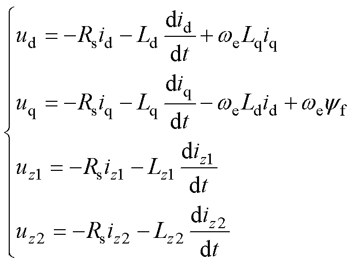
采用多相电机矢量空间解耦的方法[21-22],在自然坐标系下,将双三相电机的物理量分解到3个正交解耦的静止坐标系中,依次为:包含基波和12k±1(k=1, 2,…)次谐波的ab 子空间;包含6k±1(k= 1, 3, 5,…)次谐波的z1z2子空间;包含6k±3(k= 1, 3, 5,…)次谐波的o1o2零序子空间,采用两套绕组N1、N2中性点隔离的方式时,该空间的变量均为零。将ab 子空间再变换到旋转坐标系下,按照发电机惯例,令相电流从发电机内部流向发电机端部为正方向,最终得到四维空间下的发电机电压方程为
 (1)
(1)
式中,ud和uq为dq轴电压;uz1和uz2为z1z2子空间电压;Ld、Lq、id和iq分别为dq轴电感和电流;Lz1、Lz2、iz1和iz2分别为z1z2子空间电感和电流;Rs为定子电阻;yf为永磁磁链幅值;we为电角速度。
从式(1)可以看出,相比于三相永磁同步电机,双三相电机需要控制在z1z2子空间下的谐波电流,以减少发电机侧的损耗。
在旋转坐标系下,永磁同步发电机输出的有功功率为
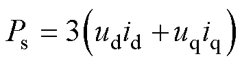 (2)
(2)
DTP-PMSG的电磁转矩方程为
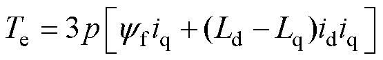 (3)
(3)
式中,p为电机极对数。
因表贴式永磁同步电机Ld=Lq,发电机输出的电磁功率为
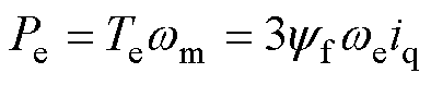 (4)
(4)
式中,wm为电机机械角速度。当发电机在id=0控制方式下,由式(4)可以看出,通过调节iq的大小,可以控制发电机的输出电磁功率。
根据物理学中对于电容器的定义,直流侧母线电容所储存的能量为
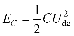 (5)
(5)
电容所储存的能量与其充电功率构成微分关系,故电容的充电功率可以表示为
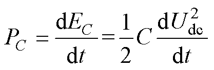 (6)
(6)
不考虑PWM整流器损耗,以直流侧电容为节点,列写电容两端的瞬时功率平衡方程为
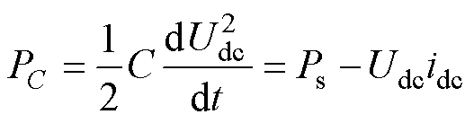 (7)
(7)
将式(1)中dq轴定子电压方程代入式(7),得到具体的瞬时功率平衡关系为
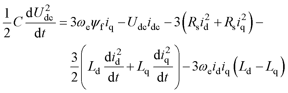 (8)
(8)
式中,左边为母线电容充电功率;右边第一项为发电机输出的电磁功率,第二项为负载消耗功率,其余项为定子电阻、电感上的损耗。若忽略这些损耗,则式(8)可以简化为
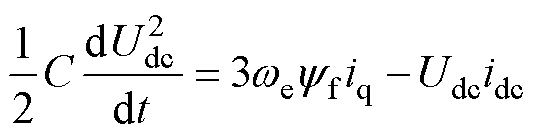 (9)
(9)
进一步整理,可以得到交轴电流为
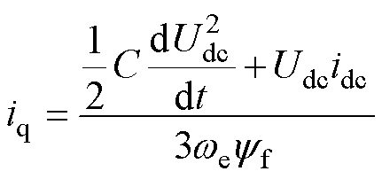 (10)
(10)
图3为DTP-PMSG PWM整流系统的控制框图,点画线框①中的电压外环为所提方法,电流内环为四维空间下的闭环控制。dq轴和z1z2子空间下的电流均使用PI控制器调节,使用id=0控制,谐波子空间电流环给定也为零。电流环的输出经交直轴解耦得到d、q轴的给定电压 、
、 。再通过Park逆变换,经最大四矢量空间电压矢量调制,控制整流器桥臂开关,实现母线电压控制。
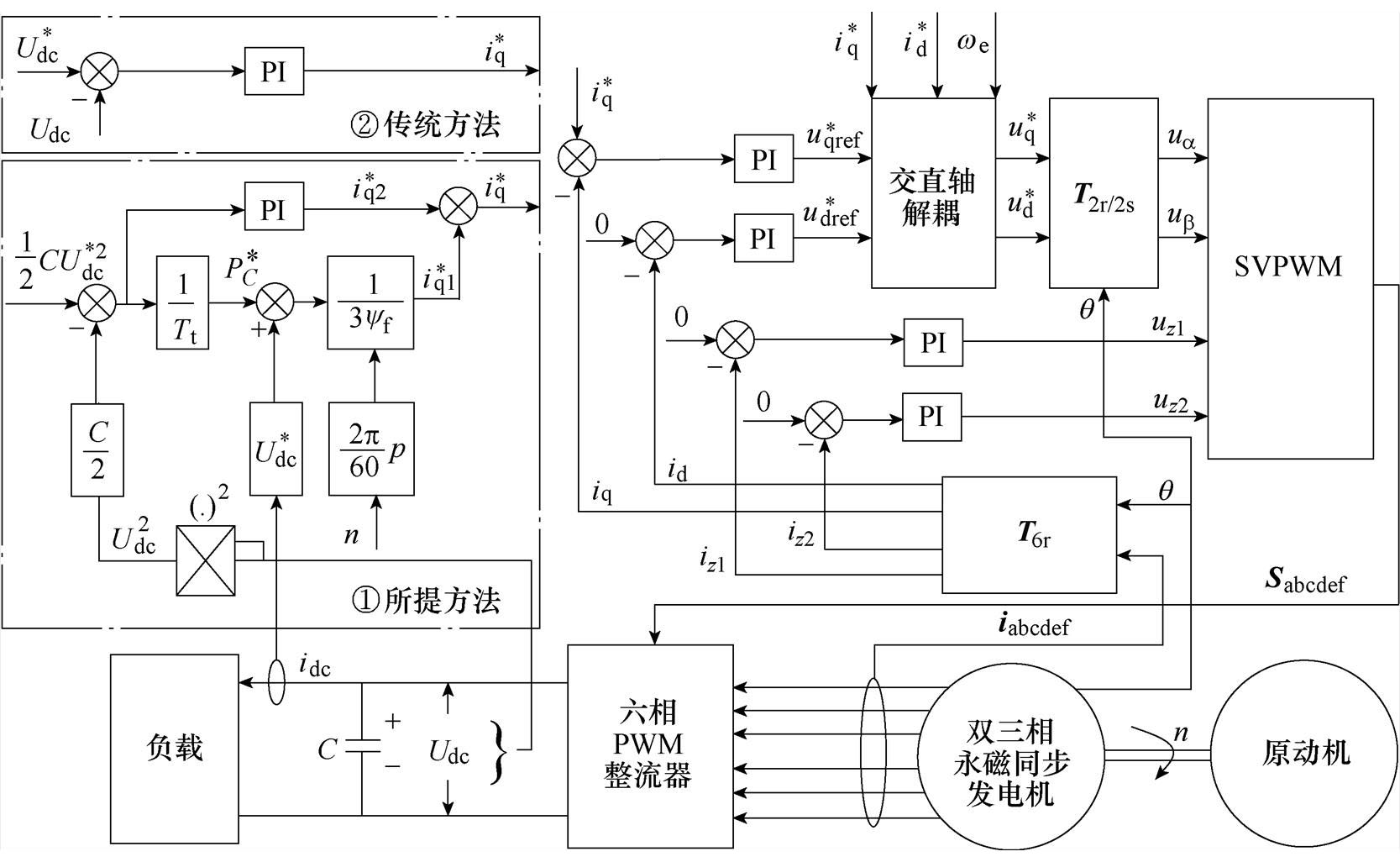
图3 DTP-PMSG PWM整流稳压控制框图
Fig.3 Voltage stabilization control structure for DTP-PMSG PWM rectifier
在传统的三相永磁同步发电机PWM整流双闭环控制中,电压外环以直流母线电压作为被控量。如图3中点画线框②所示,传统方法采用PI控制器,该方法未考虑式(10)中母线电压与交轴电流的非线性关系,不能适应负载的快速变化。
本文提出的PWM整流稳压控制策略,在不考虑系统损耗的情况下,直接计算交轴电流作为电流内环给定,实现母线电压的稳压控制。考虑实际系统中,系统存在损耗且不易估算,使用电容储能反馈,补偿这部分损耗引起的交轴电流计算误差,具有较好的母线电压控制性能。
实际系统采用数字控制实现,则根据式(10),本文提出计算交轴电流的方法为
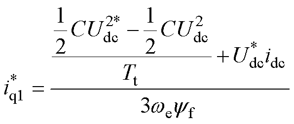 (11)
(11)
式中, 为交轴电流计算分量;Tt为电容储能达到给定的预计时间;
 为母线电压给定。
假设系统工作在一定工况下,原动机拖动发电机工作在一定转速,若突加负载,母线电压Udc跌落的同时,母线电流突然增大。在交轴电流计算时,不仅需要考虑电容储能量EC的变化对充电功率PC的需求,还需将负载功率纳入。式(11)中,将母线电压的给定与实际负载电流采样idc相乘,计算负载功率,则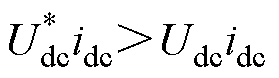 。根据式(11)得出的计算值将偏大,从而使输入系统的有功功率增加,起到加快调节的作用。加载后,流过电机相线、整流器的电流增加,系统损耗随之增加,造成原有的交轴电流计算存在误差。电容储能PI控制器起到补偿作用,
 为电容储能反馈分量,等效为交轴电流计算误差,实现母线电压稳态控制精度。减载时,分析过程同理。因此,所提的稳压控制策略能够适应负载突变工况,有效地提升了系统的抗负载扰动能力。
在电压外环设计前,需要先对电机的电流内环进行简化处理。由于交直轴电流内环、z1z2子空间谐波电流内环控制形式基本一致,因此本文选取与有功功率相关的交轴电流内环进行设计。电流内环解耦结构如图4所示,经交直轴电压解耦处理,可消除交叉耦合电动势,简化dq轴下电流内环结构。
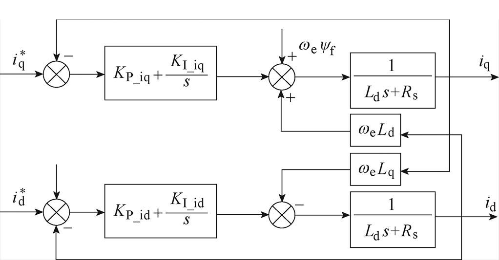
图4 电流内环解耦结构
Fig.4 Current inner loop decoupling diagram
通常的电流内环设计,忽略了数字控制存在的延时环节,不能真实反映系统中电流环的控制状况,降低电流环跟随给定的能力,进而影响外环控制效果。图5为考虑数字延时的交轴电流内环结构,将本次采样、下次更新的计算延时Ts和PWM整流器调制过程的零阶保持特性0.5Ts纳入考虑,更符合实际情况,其中Ts为电机系统控制周期。
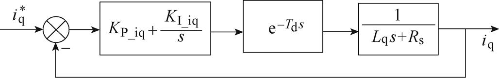
图5 交轴电流内环结构
Fig.5 Quadrature axis current inner loop structure
由于延时环节的非线性不利于参数设计,通常可用二阶Pade近似[23],延时环节的传递函数为
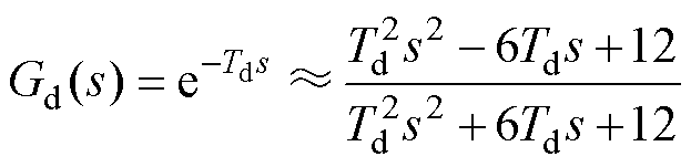 (12)
(12)
式中,Td为延时时间,Td=1.5Ts。
根据图5,电流内环的传递函数为
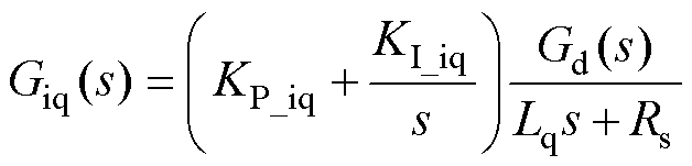 (13)
(13)
式中,KP_iq、KI_iq分别为交轴电流内环的比例、积分参数。
采用频域设计方法,对电流环进行校正。校正前的电流环开环幅频特性、PI控制器和校正后的幅频特性如图6所示。校正前截止频率wc=300rad/s,相位为-50°,相位裕度为130°。
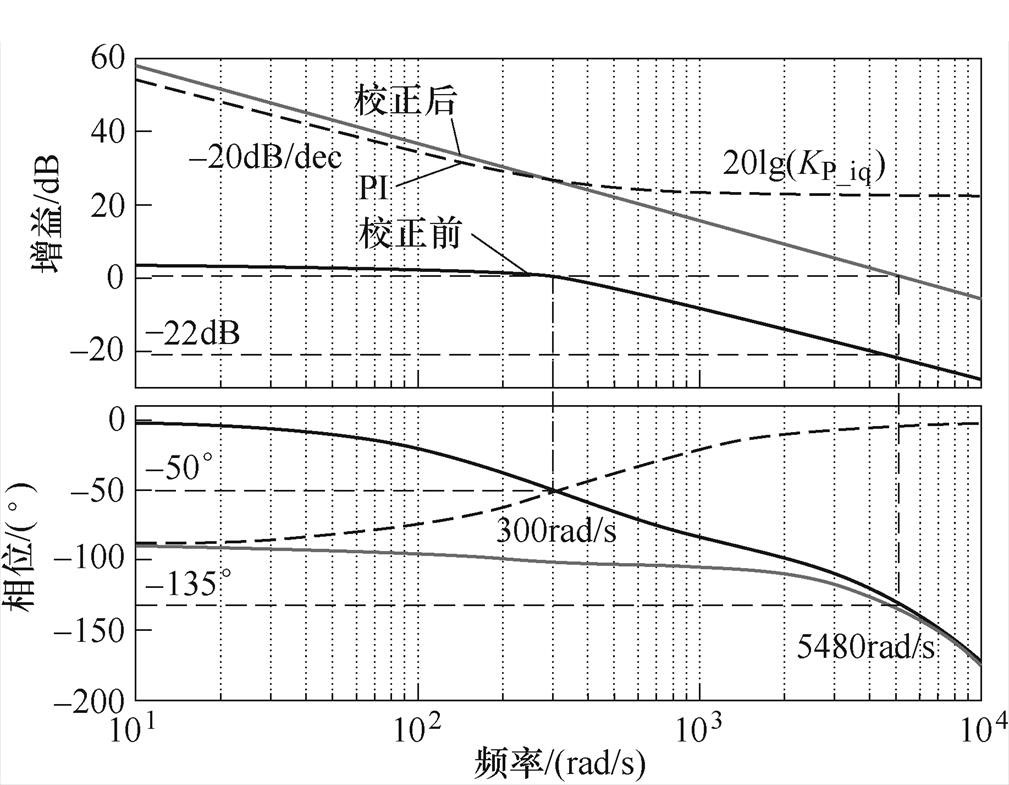
图6 电流内环频率特性
Fig.6 Frequency characteristic of current inner loop
为了控制系统的稳定,一般设计相位裕度为 45°。校正前相位为-135°的频率为5 480rad/s,幅频特性增益为-22dB。经PI控制器校正后,幅频曲线需要在5 480rad/s处穿越0dB,则令20lg(KP_iq)= 22,可得KP_iq=12.6。
校正后截止频率为5 480rad/s,为了满足相位裕度要求,控制器转折频率远离幅值穿越频率,取KI_iq/KP_iq≤0.1wc,得KI_iq=6 904.8。电流环校正后近似等效为一阶惯性环节,时间常数为Tiq=Lq/KP_iq。
校正后电流内环阶跃响应如图7所示,具有较好的响应能力。实际调试时,以设计参数为参考,进一步调整,实现较好的电流环响应。
基于电流内环的简化设计,本文所提的发电机母线电压外环控制框图如图8所示。
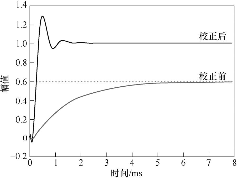
图7 电流内环阶跃响应
Fig.7 Step response of current inner loop
交轴电流的计算已由式(11)给出,包含两部分:一是电容充电功率计算;二是负载功率计算。在空载情况下分析电容充电过程,选取Tt=HTs作为电容储能调节时间,H为控制周期Ts的整数倍数,得到该段时间内母线电容充电的平均功率为
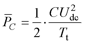 (14)
(14)
母线电容充电过程如图9所示,在k时刻,电容尚未达到目标储能量 ,假定经过Tt时间后,能充电至目标状态。按此时需要的充电功率,计算交轴电流所需大小。至k+1时刻,根据新的充电功率计算交轴电流大小,依此类推,充电功率逐步下降,最终达到目标储能量。Tt的选取偏小虽利于快速调节电容储能,但也会导致母线电压的相对稳定性下降。确定Tt时要兼顾抗负载扰动能力和相对稳定性。
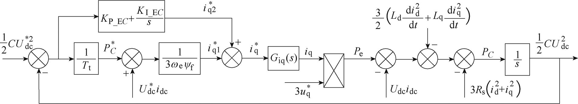
图8 DTP-PMSG母线电压外环控制框图
Fig.8 Outer loop control for bus voltage of DTP-PMSG
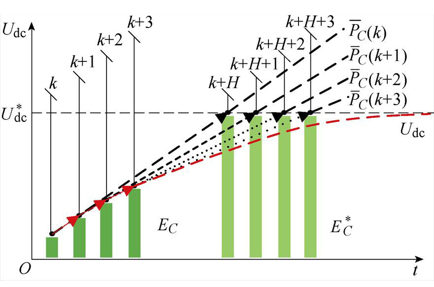
图9 母线电容充电示意图
Fig.9 Diagram of bus voltage capacitor charging
在交轴电流计算时,暂时忽略电机定子电阻、电感、PWM整流器开关损耗等。实际系统损耗存在且不易计算,需要精确的电机和整流器模型。为了补偿这部分损耗造成的交轴电流计算误差,引入电容储能反馈,达到母线电压的控制精度。电容储能反馈设计成PI控制器,有
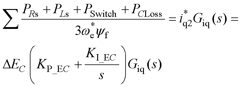 (15)
(15)
式中,PRs为电机定子电阻损耗;PLs为电机电感损耗;PSwitch为整流器开关管损耗;PCLoss为母线电容寄生参数损耗; 为给定的电机电角速度;DEC为电容储能误差;KP_EC、KI_EC分别为电容储能反馈的比例、积分参数。
在式(15)中,以电容储能作为被控量,考虑发电机系统的功率平衡关系,PI控制器起到快速响应误差、提高系统无差度的作用。控制器的比例项抑制发电机系统中快速变化的损耗功率,如加载时相电流增大导致定子绕组铜耗增加。控制器的积分项预估实际系统中变化相对缓慢、累积的损耗功率,如铁心损耗、整流器开关管导通损耗以及母线电容寄生参数发热损耗等,消除系统内多种杂散损耗带来的影响。
DTP-PMSG PWM整流系统的损耗为非线性变量,采用传递函数设计电容储能反馈的PI参数后,仍需根据实际情况对参数进行适当调整,以较好地实现对系统损耗造成的交轴电流计算误差的补偿。电容储能反馈的开环传递函数为
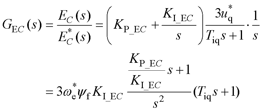 (16)
(16)
式中,为直流侧母线电容所储存能量的给定;Tiq为电流环校正后的时间常数。
式(16)与典型Ⅱ型系统的开环传递函数相近,电容储能反馈可按照典型Ⅱ型系统设计PI参数,中频宽h与PI参数关系为
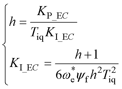 (17)
(17)
通常,选取中频宽h=5,得到设计的PI参数为
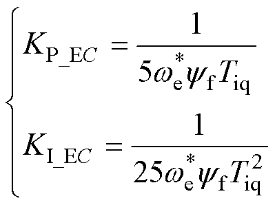 (18)
(18)
在负载突变的情况下,分析所提方法的有效性。忽略定子电阻、电感、整流器损耗,则暂不引入电容储能反馈。仅考虑负载扰动,重新整理电压外环控制框图,得到图10所示的外环控制框图。
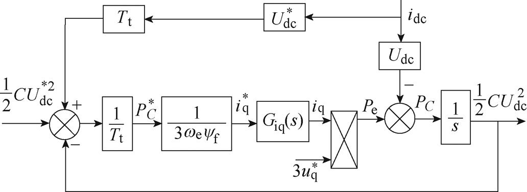
图10 负载扰动下电压外环控制框图
Fig.10 Outer loop control diagram for bus voltage under load disturbance
现求负载扰动作用下的闭环传递函数为
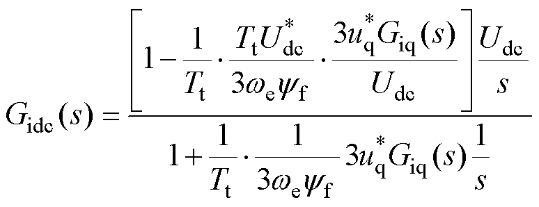 (19)
(19)
若设计Gidc(s)=0,等效为将传递函数分子置零,则电压外环的输出响应不受负载扰动影响。将式(13)代入式(19),进一步整理,可得
 (20)
(20)
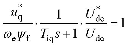
实际系统的转速采样中存在一定的高频噪声,设计一阶低通滤波器,获得相对平滑的转速,则可近似消去电流闭环。
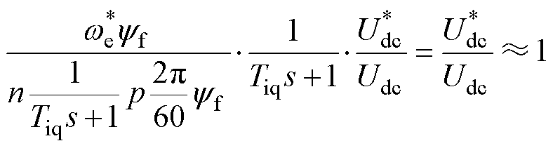 (21)
(21)
由此可得Gidc(s)=0,系统受负载扰动后的动态和稳态误差近似为零,能有效抑制扰动的影响。
基于以上所述的稳压控制策略,以DTP-PMSG为被控对象,根据图3所示的控制框图,仿真验证所提方法的可行性。并且,在双三相发电平台上对本策略进行实验验证。仿真与实验相关参数见表1,直流母线设定为150V,选取Tt为90ms数量级。通常,发电机起动阶段反电动势较小,电容储能与目标值偏差较大,采用id=0的方式起动,缓慢提升母线电压,待电机运行至一定转速时,进行正常的母线电压控制。
表1 DTP-PMSG系统参数
Tab.1 The parameters of DTP-PMSG system
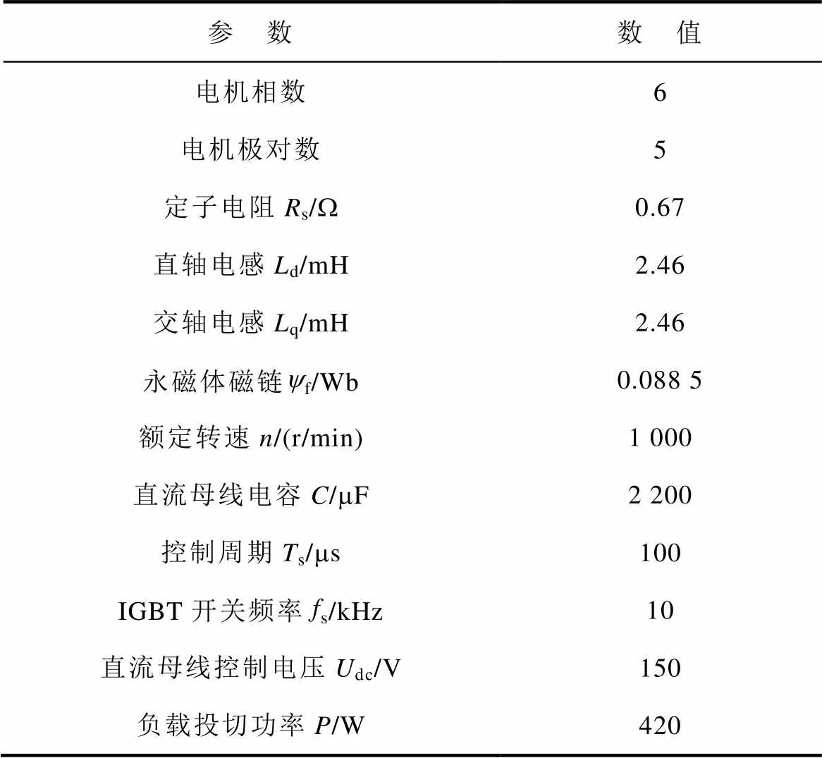
参 数数 值 电机相数6 电机极对数5 定子电阻Rs/W0.67 直轴电感Ld/mH2.46 交轴电感Lq/mH2.46 永磁体磁链yf/Wb0.088 5 额定转速n/(r/min)1 000 直流母线电容C/mF2 200 控制周期Ts/ms100 IGBT开关频率fs/kHz10 直流母线控制电压Udc/V150 负载投切功率P/W420
在相同工况,电机电流内环控制结构和参数一致的情况下,比较所提方法与传统电压外环PI控制的效果。观察仿真中母线电压的波动幅值和响应恢复速度,验证所提方法的可行性和有效性。
初始条件下直流侧电阻负载均为100W,在0.5s时刻将电阻负载切至35W,即加载420W。在1.0s时刻,又将负载切回100W,即减载420W。负载突变时母线电压对比如图11所示,相同条件下,所提方法在电压波动幅值、恢复时间上均优于传统的母线电压外环PI控制,具有较好的抗负载扰动能力。
此外,为验证交轴电流计算在交轴电流的给定中占主要分量,电容储能反馈起到辅助补偿作用;并且,在负载切换时,交轴电流计算能迅速调整,电容储能反馈补偿量有一定程度增加,将仿真工况与图11设定一致,图12给出交轴电流计算分量、电容储能反馈分量和交轴电流给定的波形。在负载为100W 轻载时,交轴电流给定与交轴电流计算近似相等,电容储能反馈近似为零。0.5s突加负载后,因系统中电流的增加,损耗随之增加,该部分由电容储能反馈补偿,等效交轴电流约为0.5A。在0.5~1.0s阶段的稳态情况下,交轴电流计算约为4.5A,给定约为5.0A,两者存在一定误差,与理论分析 一致。
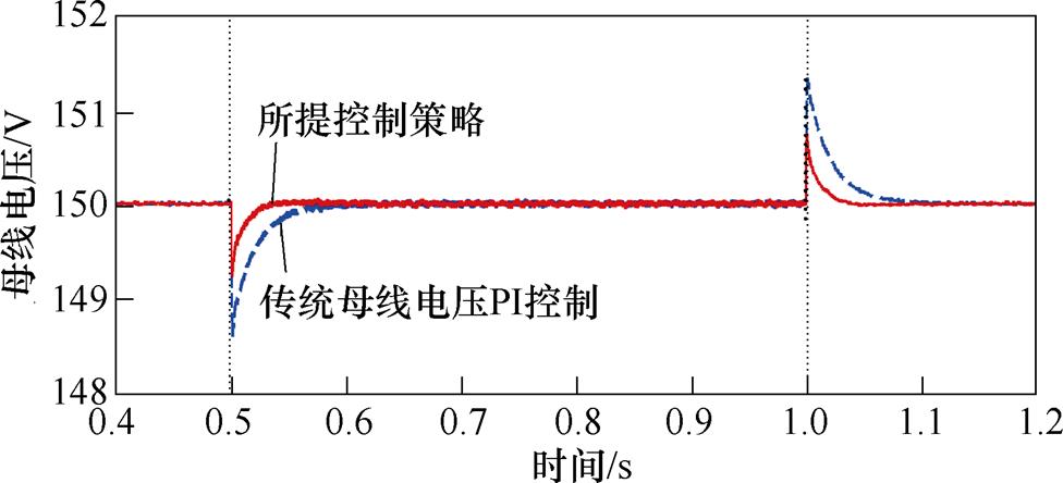
图11 负载突变时母线电压对比
Fig.11 Bus voltage comparison under abrupt load variation
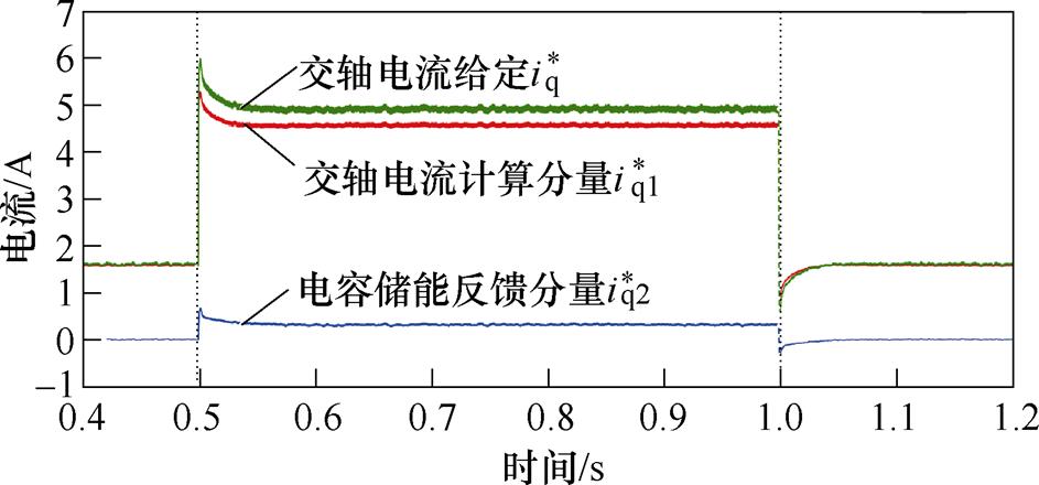
图12 交轴电流与电容储能反馈分量
Fig.12 Quadrature axis current and capacitor energy storage feedback component diagram
本文搭建DTP-PMSG PWM整流系统实验平台如图13所示。整流器使用TI公司嵌入式微控制器TMS320F28377S,采用Lattice公司CPLD芯片进行硬件上的逻辑保护,选择分立IGBT器件构建隔离驱动电路。以三相永磁同步电动机拖动DTP-PMSG的方式发电。
图14和图15分别给出传统母线电压PI控制下的加载、减载实验波形。图16和图17分别给出所提控制策略的加载、减载实验波形。实验波形从上至下依次为:母线电压、母线电流和A相电流。比较两组实验母线电压的控制效果。
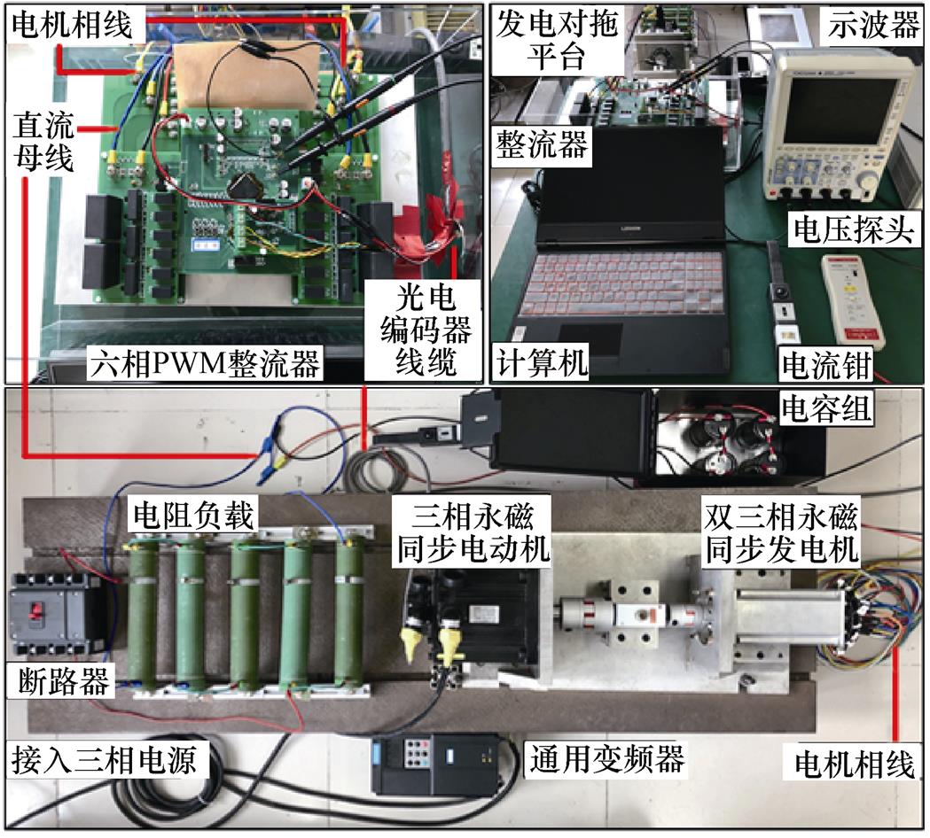
图13 DTP-PMSG PWM整流实验平台
Fig.13 Experimental platform for PWM rectifier of DTP-PMSG
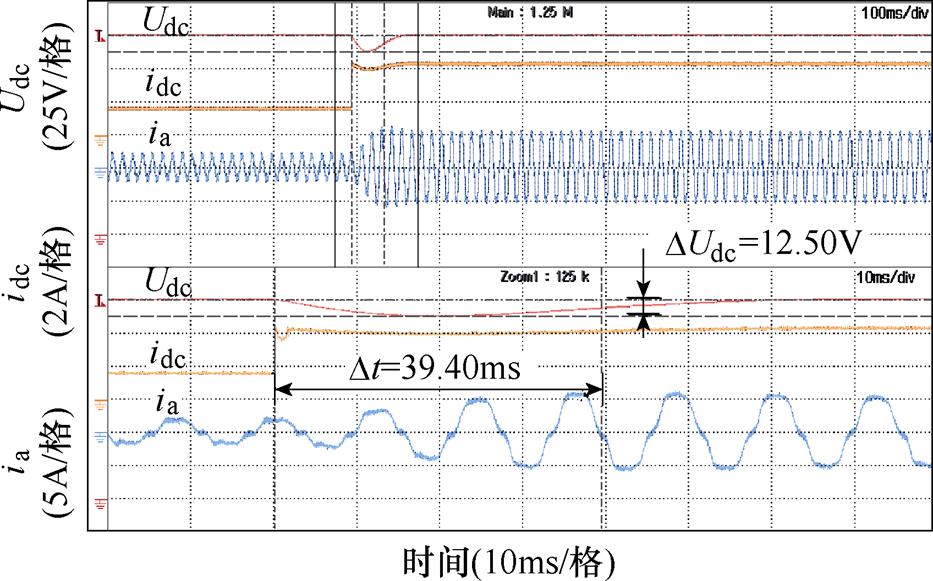
图14 传统母线电压控制加载波形
Fig.14 Load impact waveforms of the traditional bus voltage control method
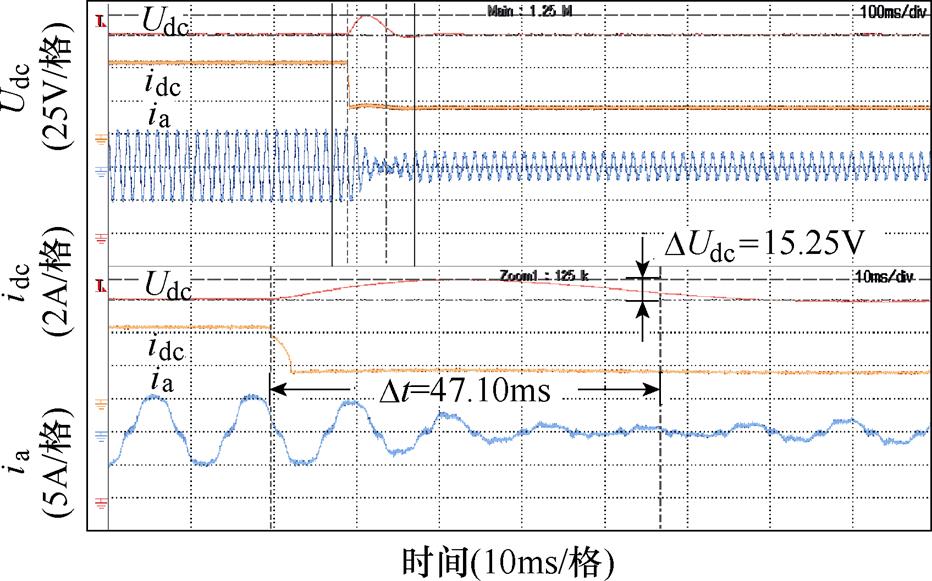
图15 传统母线电压控制减载波形
Fig.15 Load dispatch waveforms of the traditional bus voltage control method
定义直流母线电压恢复时间:突加阶跃负载扰动后,直流母线电压恢复至给定电压3%偏差以内的最短时间。传统母线电压PI控制器已将参数调至最优,避免因控制参数不适配影响比较,实验结果见表2。
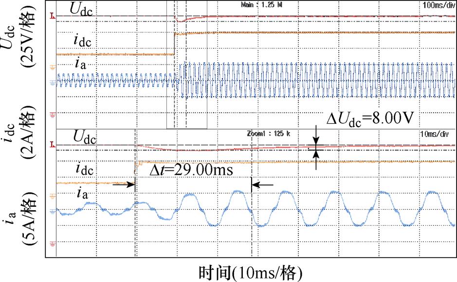
图16 所提控制策略母线电压加载波形
Fig.16 Load impact waveforms of the proposed control strategy
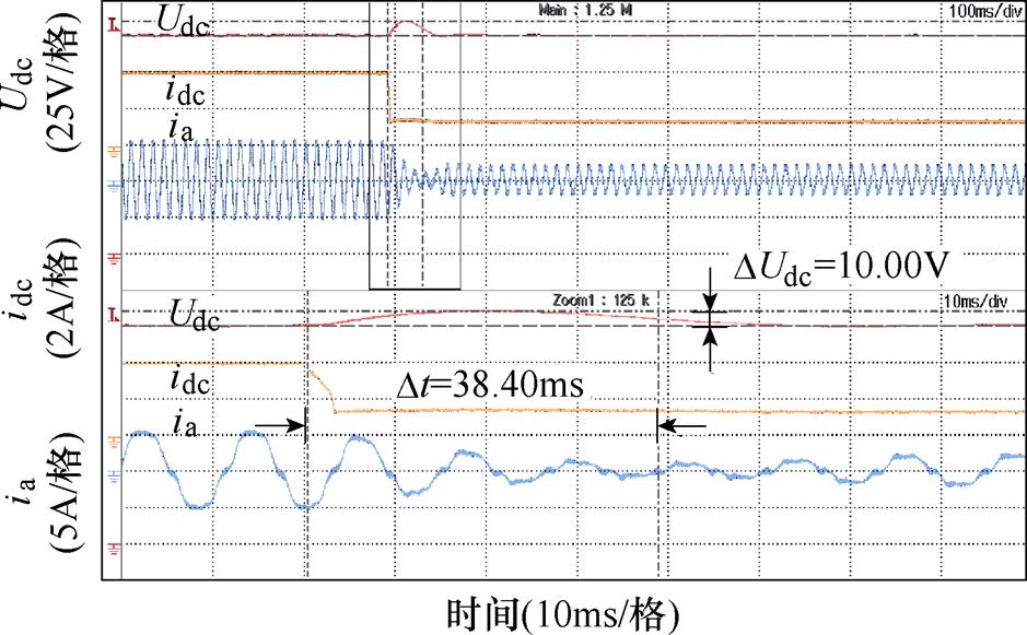
图17 所提控制策略母线电压减载波形
Fig.17 Load dispatch waveforms of the proposed control strategy
表2 传统PI方法与所提策略性能比较
Tab.2 Performance comparison between traditional PI method and proposed strategy
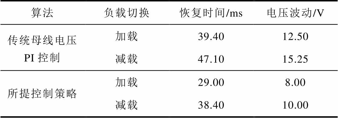
算法负载切换恢复时间/ms电压波动/V 传统母线电压 PI控制加载39.4012.50 减载47.1015.25 所提控制策略加载29.008.00 减载38.4010.00
从表2的结果可以得出,所提控制策略相较于传统方法电压恢复时间减少约20%,电压波动幅值减少约35%,具有较好的控制效果。
实验中,为了对比所提控制策略在加载、减载时的交轴电流计算与电容储能反馈比重,并且与图12的仿真结果对照,将交轴电流计算 和电容储能反馈分量
 经DSP的数模转换单元输出,其波形如图18和图19所示。实验波形从上至下依次为:母线电压、交轴电流计算、电容储能反馈和A相电流。
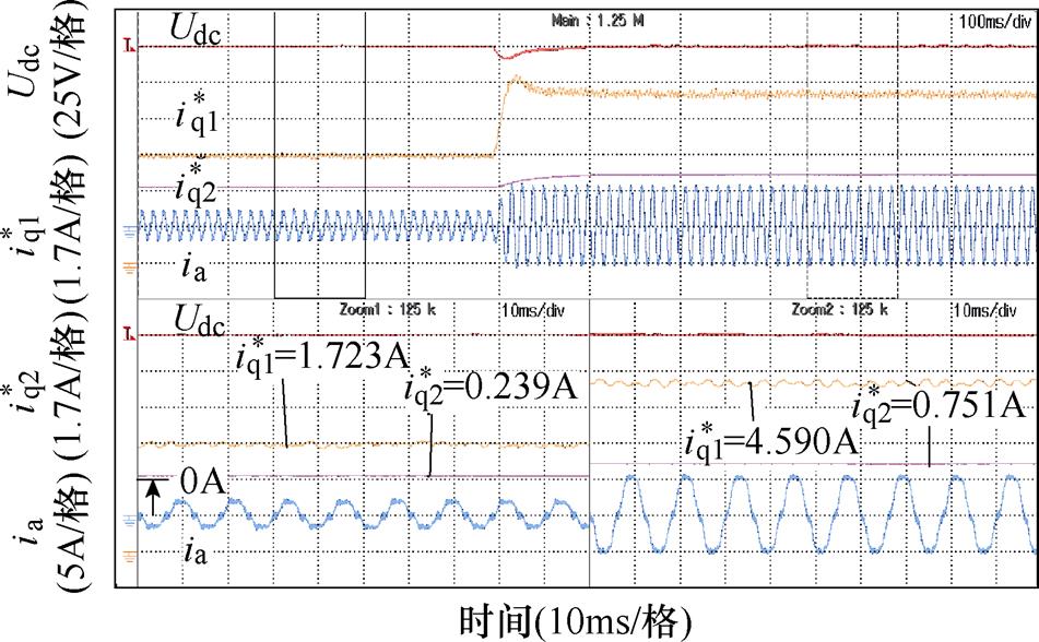
图18 加载时所提控制策略交轴电流计算与电容储能反馈分量
Fig.18 Quadrature axis current calculation and capacitor energy storage feedback component diagram of the proposed strategy when loading
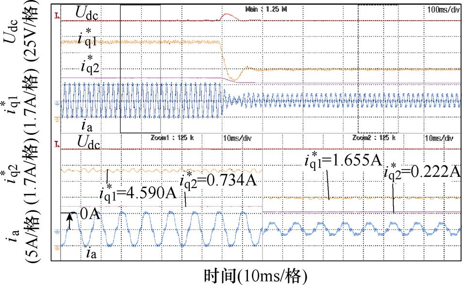
图19 减载时所提控制策略交轴电流计算与电容储能反馈分量
Fig.19 Quadrature axis current calculation and capacitor energy storage feedback component diagram of the proposed strategy when unloading
可知,交轴电流计算能根据负载投切状态迅速响应,避免母线电压大幅跌落或者泵升,与理论分析相吻合。给出了电容储能反馈补偿量的数值大小,轻载时补偿量等效约为0.2A交轴电流,加载后需要0.7A左右的补偿。电容储能反馈分量在加载和减载过程中,能够经一定时间补偿系统损耗带来的误差,其变化规律与仿真结果一致,轻载时补偿量小,加载后补偿量增加。
图20给出不同Tt参数下,突减负载时母线电压的响应波形,所提方法在母线电压波动幅值上均小于传统PI控制方式。母线电压的波动幅值随Tt参数的减小而减小,但电压的振荡随Tt参数的减小而增加。综合考虑母线电压的恢复时间和母线电压振荡,确定Tt参数为90ms合适。
在减载的工况下,仅改变永磁体磁链和电容容值,图21和图22分别给出磁链和电容容值的变化
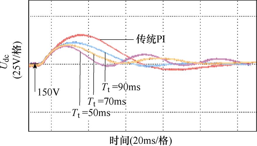
图20 母线电压响应波形
Fig.20 Bus voltage response waveforms
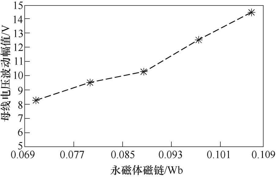
图21 母线电压波动幅值与永磁体磁链关系
Fig.21 Relationship between bus voltage fluctuation amplitude and permanent magnetic chain
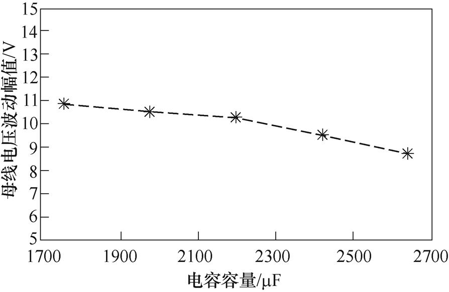
图22 母线电压波动幅值与电容容量关系
Fig.22 Relationship between bus voltage fluctuation amplitude and capacitance value
对母线电压波动幅值的影响。可知,稳压控制的性能对磁链参数具有一定的依赖性,因为交轴电流计算占主导成分,与磁链成反比,进而影响母线电压。只要确保样机的磁链参数测量不出现较大误差,即可保证算法的有效性。而电容容值的变化对母线电压的影响较小,算法可以适应实际电容容值的误差。
本文建立直流母线电容能量和功率交换数学模型,提出了基于交轴电流计算和电容储能反馈的DTP-PMSG系统PWM整流稳压控制策略,以满足高端装备领域中对于发电机整流系统的电压要求。通过解析计算,直接得到交轴电流内环的给定,替代传统方法仅依赖PI控制器调节的电压外环,加快了电压外环的响应。为了补偿因系统损耗造成的交轴电流计算误差,引入电容储能反馈,达到母线电压控制的精度。该方法简单有效、易于实现,在直流母线电压外环的控制方面,物理意义更加明确。相比于传统的母线电压外环PI控制,所提方法能有效缩短母线电压恢复时间,降低母线电压波动幅值。仿真和实验结果表明,该方法具有较好的抗负载扰动能力,能实现母线电压的高性能控制。本文以DTP-PMSG作为实验对象分析,下一步将所提方法拓展,根据普通三相永磁同步电机数学模型进行适当修改,也同样适应。
参考文献
[1] Wang Qingsong, Zha Daojun, Cheng Ming, et al. Energy management system for DC electric spring with parallel topology[J]. IEEE Transactions on Industry Applications, 2020, 56(5): 5385-5395.
[2] 朱晓荣, 李铮, 孟凡奇. 基于不同网架结构的直流微电网稳定性分析[J]. 电工技术学报, 2021, 36(1): 166-178.
Zhu Xiaorong, Li Zheng, Meng Fanqi. Stability analysis of DC microgrid based on different grid structures[J]. Transactions of China Electrotechnical Society, 2021, 36(1): 166-178.
[3] 刘计龙, 朱志超, 肖飞, 等. 一种面向舰船综合电力系统的模块化三端口直流变换器[J]. 电工技术学报, 2020, 35(19): 4085-4096.
Liu Jilong, Zhu Zhichao, Xiao Fei, et al. A modular three-port DC-DC converter for vessel integrated power system[J]. Transactions of China Electro- technical Society, 2020, 35(19): 4085-4096.
[4] Gao Jian, Dai Litao, Zhang Wenjuan, et al. Multi- interval efficiency design optimization for permanent magnet synchronous generators used in hybrid electric special vehicles[J]. IEEE Transactions on Industrial Electronics, 2021, 68(6): 4646-4656.
[5] Boglietti A, Bojoi R, Rubino S, et al. Load capability of multiphase machines under normal and open-phase fault conditions[C]//2018 IEEE Energy Conversion Congress and Exposition (ECCE), Portland, OR, USA, 2018: 242-247.
[6] Zhu Shengdao, Zhao Wenxiang, Liu Guohai, et al. Effect of phase shift angle on radial force and vibration behavior in dual three-phase PMSM[J]. IEEE Transactions on Industrial Electronics, 2021, 68(4): 2988-2998.
[7] 田代宗, 孙宇光, 王善铭, 等. 多相整流永磁同步发电机绕组内部相间短路的故障分析[J]. 电工技术学报, 2020, 35(6): 1262-1271.
Tian Daizong, Sun Yuguang, Wang Shanming, et al. Analysis of stator internal phase-to-phase short- circuit in the multiphase permanent magnet syn- chronous generator with rectifier load system[J]. Transactions of China Electrotechnical Society, 2020, 35(6): 1262-1271.
[8] Hu Yashan, Li Yonggang, Ma Xiandong, et al. Flux- weakening control of dual three-phase PMSM based on vector space decomposition control[J]. IEEE Transactions on Power Electronics, 2021, 36(7): 8428-8438.
[9] Yeoh S S, Yang Tao, Tarisciotti L, et al. Permanent- magnet machine-based starter-generator system with modulated model predictive control[J]. IEEE Transa- ctions on Transportation Electrification, 2017, 3(4): 878-890.
[10] Su Yulan, Ge Xinglai, Xie Dong, et al. An active disturbance rejection control-based voltage control strategy of single-phase cascaded H-bridge recti- fiers[J]. IEEE Transactions on Industry Applications, 2020, 56(5): 5182-5193.
[11] Zhang Yongchang, Wang Zeting, Jiao Jian, et al. Grid-voltage sensorless model predictive control of three-phase PWM rectifier under unbalanced and distorted grid voltages[J]. IEEE Transactions on Power Electronics, 2020, 35(8): 8663-8672.
[12] 肖雄, 武玉娟, 孙广达, 等. 基于自适应神经网络观测的无电压传感器PWM整流器功率预测控制[J]. 中国电机工程学报, 2021, 41(3): 1135-1146.
Xiao Xiong, Wu Yujuan, Sun Guangda, et al. Voltage-sensorless model predictive power control of PWM rectifier based on adaptive neural network observation[J]. Proceedings of the CSEE, 2021, 41(3): 1135-1146.
[13] 王占扩, 张永昌, 童朝南. 一种改进的三相PWM整流器模型预测控制方法研究[J]. 电机与控制学报, 2020, 24(7): 73-81.
Wang Zhankuo, Zhang Yongchang, Tong Chaonan. Improved model predictive direct power control for three-phase PWM rectifier[J]. Electric Machines and Control, 2020, 24(7): 73-81.
[14] 苏晓英, 朱连成, 金石, 等. 一种复合转子无刷双馈风力发电机直接功率控制研究[J]. 电工技术学报, 2020, 35(3): 494-501.
Su Xiaoying, Zhu Liancheng, Jin Shi, et al. Research on direct power control for brushless doubly-fed wind power generator with a novel hybrid rotor[J]. Transactions of China Electrotechnical Society, 2020, 35(3): 494-501.
[15] Liu Senyi, Liu Chunhua. Virtual-vector-based robust predictive current control for dual three-phase PMSM[J]. IEEE Transactions on Industrial Elec- tronics, 2021, 68(3): 2048-2058.
[16] Ren Yuan, Zhu Z Q, Green J E, et al. Improved duty- ratio-based direct torque control for dual three-phase permanent magnet synchronous machine drives[J]. IEEE Transactions on Industry Applications, 2019, 55(6): 5843-5853.
[17] Niu Feng, Chen Xi, Huang Shaopo, et al. Model predictive current control with adaptive-adjusting timescales for PMSMs[J]. CES Transactions on Electrical Machines and Systems, 2021, 5(2): 108- 117.
[18] 姜卫东, 李王敏, 佘阳阳, 等. 直流电容储能反馈和负载功率前馈的PWM整流器控制策略[J]. 电工技术学报, 2015, 30(8): 151-158.
Jiang Weidong, Li Wangmin, She Yangyang, et al. Control strategy for PWM rectifier based on feedback of the energy stored in capacitor and load power feed-forward[J]. Transactions of China Electro- technical Society, 2015, 30(8): 151-158.
[19] 甘志伟, 缪冬敏, 王云冲, 等. 宽转速范围永磁同步发电机系统稳压控制及参数优化[J]. 电工技术学报, 2020, 35(8): 1624-1633.
Gan Zhiwei, Miao Dongmin, Wang Yunchong, et al. Voltage stabilization control and parameters optimi- zation for wide-speed-range permanent magnet synchronous generator systems[J]. Transactions of China Electrotechnical Society, 2020, 35(8): 1624- 1633.
[20] Zhang Xiang, Yang Jiaqiang. A robust flywheel energy storage system discharge strategy for wide speed range operation[J]. IEEE Transactions on Industrial Electronics, 2017, 64(10): 7862-7873.
[21] 张建亚, 王凯, 朱姝姝, 等. 双三相永磁同步电机多谐波电流协同控制策略[J]. 中国电机工程学报, 2020, 40(2): 644-652.
Zhang Jianya, Wang Kai, Zhu Shushu, et al. Control strategies of dual three-phase permanent magnet machines with multi-harmonics[J]. Proceedings of the CSEE, 2020, 40(2): 644-652.
[22] Feng Guodong, Lai Chunyan, Li Wenlong, et al. Dual reference frame based current harmonic minimization for dual three-phase PMSM considering inverter voltage limit[J]. IEEE Transactions on Power Elec- tronics, 2021, 36(7): 8055-8066.
[23] 曹靖洺, 董朝宇, 肖迁, 等. 考虑控制与通信多成分时滞的多端MMC-HVDC信息物理系统统一建模与互联稳定性分析[J]. 中国电机工程学报, 2021, 41(10): 3547-3560, 3679.
Cao Jingming, Dong Chaoyu, Xiao Qian, et al. State modeling and stability analysis of the multi-terminal MMC-HVDC cyber-physical system considering the control and communication delay[J]. Proceedings of the CSEE, 2021, 41(10): 3547-3560, 3679.
Voltage Stabilization Control for Dual Three-Phase Permanent Magnet Synchronous Generator System Based on Quadrature Axis Current Calculation and Feedback of the Energy Stored in Capacitor
Abstract In full electrification of high-end equipment, such as special vehicles, warships and aircraft, direct current power systems with generators as the core works under the condition of rapid load change. The dual three-phase permanent magnet synchronous generator (DTP-PMSG) has a high fault tolerance rate, low voltage, and high power, suitable for the high-end equipment field limited by output voltage and space volume. However, without considering the nonlinear relationship between bus voltage and quadrature axis current, the conventional bus voltage control method had the disadvantages of long voltage recovery time and large voltage fluctuation when the load changes rapidly. Recently, some methods were presented to analyze the physical meaning of the voltage outer loop and establish the connection between bus voltage and output power, but most of them suffered from high design costs due to complex control parameter. To address these issues, this paper proposes a voltage stabilization control strategy based on quadrature axis current calculation and feedback of the energy stored in capacitor.
Firstly, the DTP-PMSG mathematical model is established to deduce the relationship between electromagnetic power and quadrature axis current. Secondly, according to PWM rectifier topology, the mathematical model of the energy and power exchange of the bus capacitor is established to derive the calculation formula of quadrature axis current. Thirdly, combined with the digital realization of the actual control system, the designed time parameter optimizes quadrature axis current calculation formula. Finally, considering that the calculated value of the quadrature axis current will have errors due to the inaccuracy of the DTP-PMSG mathematical model, a capacitor energy storage PI controller is designed to compensate the errors caused by the modeling and realizes the accurate control of the bus voltage.
Simulation results show that, when the load is 100W, the calculated quadrature axis current value accounts for the main component of the given quadrature axis current, and the values are almost equal. After sudden loading to 35W, the calculation of quadrature axis current adjusts quickly to 4.5A to meet output power requirements. Meanwhile, the increase of system power brings about the increase of loss, resulting in an equivalent 0.5A quadrature current loss, which is compensated by capacitor energy storage feedback. Then the experimental results are consistent with the simulation results. Compared with the traditional method, the proposed control strategy reduces the voltage recovery time by about 20% and the voltage fluctuation amplitude by about 35%, which demonstrates the effectiveness of using the proposed. In addition, the experiment draws the curve of bus voltage fluctuation amplitude with flux linkage and capacitance value. The trend suggests that the proposed control strategy has a certain dependence on the flux linkage parameter, the change of the capacitance value has little influence on the bus voltage, and the strategy can adapt to the error of the actual capacitor value.
The following conclusions can be drawn from the simulation and experimental analysis: ① Through the calculation of quadrature axis current, the setting of the quadrature axis current inner loop is directly obtained, replacing the traditional method that only relies on the voltage outer loop adjusted by the PI controller, and speeding up the response of the voltage outer loop. ② The introduction of capacitive energy storage feedback compensates the calculation error of the quadrature axis current caused by system loss to achieve the accuracy of bus voltage control. Based on clear physical implications, the proposed method can effectively shorten the bus voltage recovery time and reduce the voltage fluctuation amplitude. Although this paper takes DTP-PMSG as the experimental object for analysis, and the method is also applicable to three-phase permanent magnet synchronous motors after proper modification.
keywords:Quadrature axis current calculation, capacitor energy storage feedback, voltage fluctuation, recovery time, permanent magnet synchronous generator
中图分类号:TM351
DOI: 10.19595/j.cnki.1000-6753.tces.211521
国家杰出青年科学基金资助项目(52025073)。
收稿日期 2021-09-27
改稿日期 2021-12-10
E-mail: 792667420@qq.com
赵文祥 男,1976年生,教授,博士生导师,研究方向为电机设计与控制。
E-mail: zwx@ujs.edu.cn(通信作者)
(编辑 崔文静)