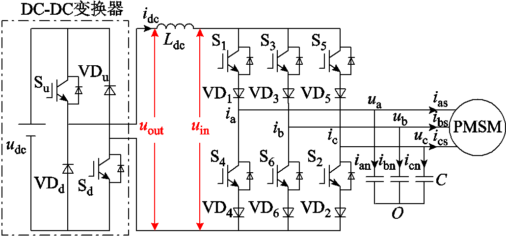
图1 CSI电机驱动系统拓扑结构
Fig.1 Topology of CSI motor drive system
摘要 电流源型逆变器(CSI)电机驱动系统通常使用电压源串联电感来实现恒定的直流链电流,然而因这种方式未对直流链电流进行控制,直流链电流会出现断续或持续增加的问题。为此,采用DC-DC变换器电路设计PI控制器,可以实现对直流链电流的控制。同时,详细分析一个周期内DC-DC变换器与CSI的电压变化规律,通过优化CSI的电流矢量序列,使得直流链电流纹波得到抑制,提高了输出端电机的电流波形质量。实验结果验证了所提出的直流链电流控制方法的可行性与有效性。
关键词:电流源型逆变器 直流链电流 电流矢量序列 直流链电流纹波
电机驱动系统按照直流侧电源的类型可以分为电压源型逆变器(Voltage Source Inverter, VSI)拓扑和电流源型逆变器(Current Source Inverter, CSI)拓扑[1]。目前,电机驱动系统多采用VSI拓扑[2-4],其直流侧需并联大容量的薄膜电容或电解电容,但由于薄膜电容的体积较大,电解电容存在寿命短的缺陷[5]。此外,VSI还具有短路的风险。不同于VSI,CSI使用电感作为储能元件,电感的可靠性高,同时CSI具有输出电流波形质量高、可以实现电机负载四象限运行、固有的短路保护功能以及升压功能拓宽了电机恒功率运行范围的优点[6-8]。近年来,随着CSI中电感元件的储能效率问题得到解决,以及先进材料制造的高速半导体功率开关管成功研发,CSI的研究也越来越广泛[9-12]。
由于CSI的拓扑结构、工作原理不同于VSI,因此不能直接将VSI的控制策略应用于CSI。针对CSI驱动系统的控制,国内外学者进行了大量的研究。文献[13]针对电流源型永磁同步电机(Permanent Magnetic Synchronous Machine, PMSM)系统,使用两种不同的解耦方法并结合有源阻尼法设计了电流电压双闭环控制策略,实现了对电机定子电流的控制并减小了谐振的影响。但是,该方法仅仅是对交流侧进行调制与控制策略研究,没有考虑直流侧的直流链电流问题。文献[14]在直流侧的直流链电感上并联旁路开关,在直流链电流增大时通过开通旁路开关有效地抑制了直流链电流的增加。文献[15]为了实现CSI电机驱动系统的能量回馈,提出了一种DC-DC变换器拓扑的结构。然而,文献[14-15]虽然考虑了直流侧的直流链电流问题,但是均未给出针对改进拓扑的直流链电流控制策略。
另一方面,CSI系统的直流链电流需以低电流纹波向逆变器的输入端提供直流电流,以使逆变器的脉宽调制(Pulse Width Modulation, PWM)算法能够精确调节三相电流的幅值和频率[16]。文献[17]研究了感应电机转子磁链与直流链电流的关系,通过前端整流器实现了最小直流链电流的控制,降低了电感损耗,但并没有考虑直流链电流纹波的问题。文献[18-19]针对背靠背型的电流源变换器,通过协调整流器与逆变器矢量作用的顺序,减小了系统的共模电压与直流链电流纹波,但仅适用于前端采用整流器的背靠背型系统。文献[20]通过电流纹波分析模型推导电流纹波的表达式,提出一种适合宽范围运行下的直流链电流纹波的优化调制策略,但是该策略控制目标是电流源型整流器,不适用于CSI。
本文采用DC-DC变换器电路,在基于转子磁场定向控制与直流链电流PI控制基础上设计了CSI永磁同步电机的控制系统,并且在分析了一个周期内DC-DC变换器与CSI电压变化后,通过优化CSI的电流矢量序列抑制了直流链电流的纹波。本文搭建了实验平台,验证了所提出方法的有效性。
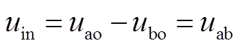
CSI电机驱动系统的拓扑结构如图1所示,不同于VSI在直流侧提供恒定的直流电压,CSI在直流侧需要恒定的直流链电流,本文前端采用DC-DC变换器串联电感来实现恒定的直流链电流idc。S1~S6为逆变桥的6个开关管;VD1~VD6为与开关管串联的二极管;C为输出侧并联的三相电容;ia、ib、ic为CSI输出电流;ua、ub、uc为输出端三相电容电压,同时也是电机的三相定子电压;uout为DC-DC变换器的输出电压;uin为CSI的输入电压。在CSI系统中,由于直流链电路中串接了电感,为了保证电流的单向性,逆变桥在同一时刻只能有两个开关管导通,且必须一个在上桥臂,另一个在下桥臂,因此三相CSI共有9种开关状态,对应9个空间电流矢量,其中包括6个有效矢量和3个零矢量。
图1 CSI电机驱动系统拓扑结构
Fig.1 Topology of CSI motor drive system
如图1所示,DC-DC变换器由两个开关管Su、Sd和两个二极管VDu、VDd组成,通过控制两个开关管的开通与关断,DC-DC变换器共包含供电模式、续流模式和充电模式三种工作模式。两个开关管不同开关状态对应的工作模式分别如图2所示。
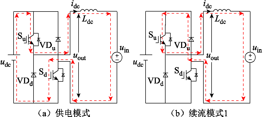
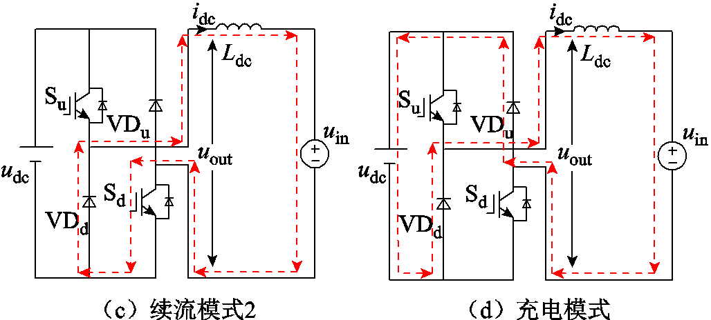
图2 DC-DC变换器工作模式
Fig.2 Working mode of DC-DC converter
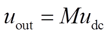
DC-DC变换器的输出电压uout为
 (1)
(1)
式中,M为DC-DC变换器的电压调制比;udc为直流电压。
本文设计的直流链电流控制策略仅使用DC-DC变换器的续流模式和供电模式。开关管Su始终处于导通状态,当直流链电流大于给定值时,开关管Sd关断,处于续流模式1,使idc减小;当直流链电流小于给定值时,开关管Sd导通,处于供电模式,使idc增大。这样,仅通过控制开关管Sd即可实现对直流链电流的控制。
基于转子磁场定向控制的CSI电机驱动系统控制框图如图3所示。其中直流链电流的控制策略为:将直流链电流检测值与给定值的偏差输入PI控制器,得到开关管Sd的占空比,继而实现对DC-DC变换器调制比M的控制,调节直流链电流idc,为CSI提供恒定的直流链电流,实现电流调制。永磁同步电机的控制以转速环为最外环,内环采用电流、电压双闭环控制。
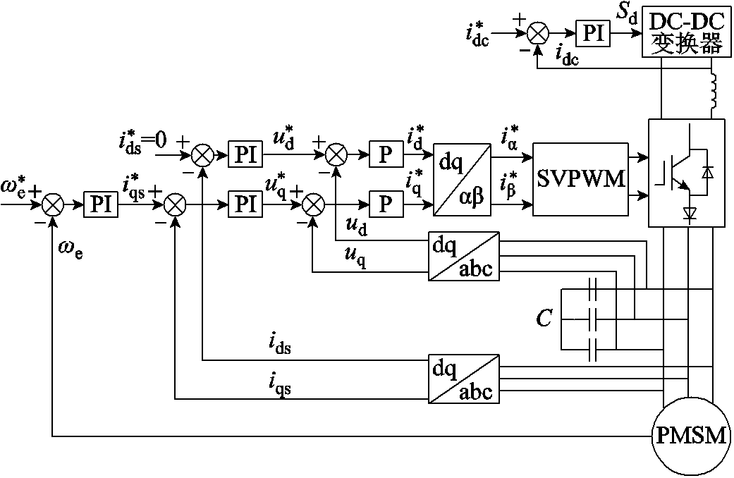
图3 CSI电机驱动系统控制框图
Fig.3 Control block diagram of CSI motor drive system
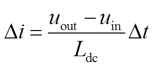
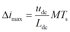
在CSI系统中,若直流链电流纹波大,不仅会增大电感损耗和开关损耗,导致电磁干扰,还会引发交流侧电流畸变[21]。第1节所述的CSI电机驱动系统分别实现了对电机定子电流与直流链电流的独立控制,并没有考虑直流链电流的纹波,以下将对直流链电流纹波进行分析。由图1可知,直流链电流的纹波表达式为
 (2)
(2)
式中,Ldc为电感值;Dt为一个周期的充放电时间。由式(2)可知,通过增大电感值或提高开关频率可以减小直流链电流纹波。然而,增大电感值会导致系统体积增大,提高开关频率会增大系统开关损耗。可以进一步看出,纹波还与电感两端的电压差有关,减小电感两端的电压差uout-uin也能减小电流纹波。而电压差uout-uin与一个周期内DC-DC变换器的输出电压和CSI的输入电压有关,因此需要分析一个周期内DC-DC变换器与CSI的电压变化情况。
首先,分析CSI的输入电压变化情况。CSI采用SVPWM时对应的9个空间电流矢量分布如图4所示,电流矢量将空间划分为6个扇区。
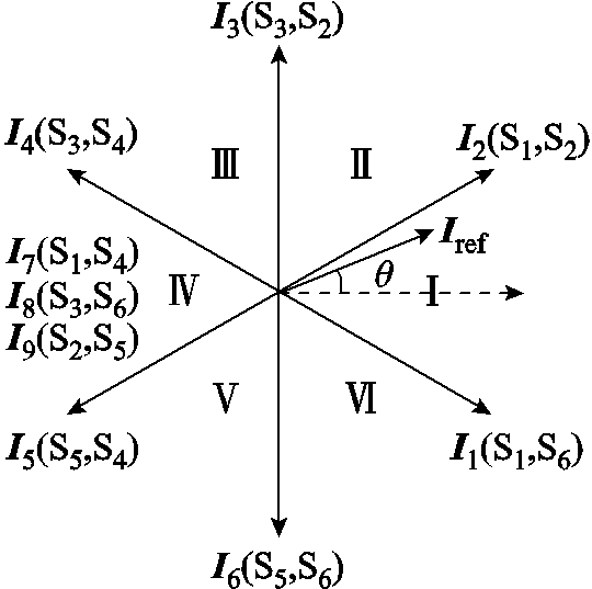
图4 空间电流矢量分布
Fig.4 Space current vector distribution
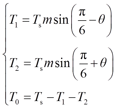
空间矢量调制按照“安秒平衡原则”,使用两个有效矢量I1、I2和一个零矢量I0来合成参考矢量,以图4中参考矢量Iref位于第一扇区为例,利用有效矢量I1、I2和零矢量I7来合成参考矢量Iref,计算出各矢量的作用时间分别为
 (3)
(3)
式中,T1、T2、T0分别为有效矢量I1、I2和零矢量I7的作用时间;Ts为一个周期;m为CSI的电流调制比,m=|Iref|/idc;q为电流矢量角。
当CSI的电流矢量作用时,以电流矢量I1为例,此时只有开关管S1和S6导通,根据基尔霍夫电压定律,CSI的输入电压可表示为
 (4)
(4)
由式(4)可知,电流矢量I1作用时CSI的输入电压为电机的线电压,而电机的线电压可表示为
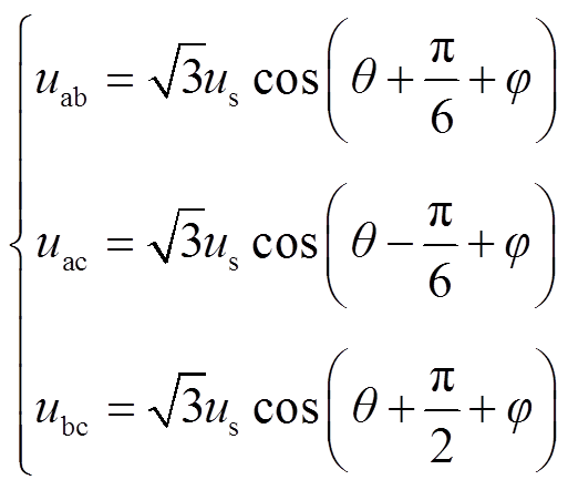 (5)
(5)
式中,us为电机相电压;j为电机的功率因数角。
同理可以计算出其他电流矢量作用时对应的输入电压。由此可得不同电流矢量作用时的开关状态和CSI输入电压见表1。
表1 空间矢量/开关状态与CSI输入电压
Tab.1 Space vector/switching stages and input voltage of CSI

空间矢量导通开关输入电压uin 有效矢量I1(S1, S6)uab I2(S2, S1)uac I3(S3, S2)ubc I4(S4, S3)-uab I5(S5, S4)-uac I6(S6, S5)-ubc 零矢量I7(S1, S4)0 I8(S3, S6)0 I9(S5, S2)0
其次,分析一个周期内DC-DC变换器的输出电压变化情况。当系统在稳态情况下,根据电感的伏秒平衡原理,电感电压在一个周期内的变化为0,可得表达式为
 (6)
(6)
根据式(6)可知,电压积分包含DC-DC变换器的电压积分和CSI的电压积分两部分。一个周期内,DC-DC变换器的电压积分为
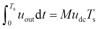 (7)
(7)
CSI的电压积分需根据电流矢量对应的输入电压和矢量作用时间来计算。以第一扇区为例,结合式(3)和式(5)及表1可计算出CSI的电压积分为
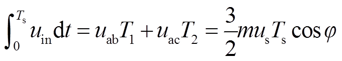 (8)
(8)
将式(8)与式(7)代入式(6)可得到
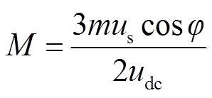 (9)
(9)
由式(9)可知,当电机在稳态运行时,由于CSI的电流调制比m、电机的相电压us、电机的功率因数角j、直流电压udc均固定,DC-DC变换器的电压调制比M也为定值。根据以上分析可知,一个周期内DC-DC变换器会有MTs时间段输出电压为udc,而其余时间输出为0。
根据第2节所述,一个周期内CSI输入电压和DC-DC变换器输出电压的变化情况可分析电感两端的电压差uout-uin。本文CSI采用三段式SVPWM,所以在一个周期中CSI输入电压的组合顺序有六种,而DC-DC变换器输出电压固定为udc和0,因此电感两端的电压差uout-uin存在多种情况,相应的纹波大小也不同。本文通过改变CSI的电流矢量作用顺序来分析直流链电流纹波情况。
传统方案不考虑CSI的电流矢量作用顺序,导致直流链电流纹波大。以第一扇区为例,若电流矢量作用顺序固定为I1→I2→I7,并假定电流矢量I1、I2对应的输入电压uab>uac,根据DC-DC变换器的输出电压及CSI输入电压可画出一个周期内的电流纹波波形,如图5a所示。此时DC-DC变换器输出udc的时间段与零矢量I7重叠。根据图5a及式(2)可求得最大电流纹波为
 (10)
(10)
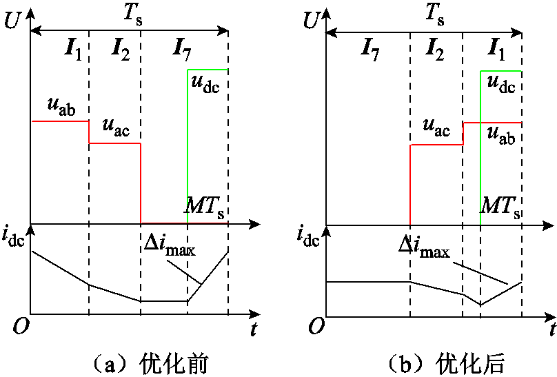
图5 一个开关周期内电流纹波波形
Fig.5 Waveforms of current ripple in one switching cycle
上述传统方案由于没有考虑电感两端的电压差,最大电压差达到udc。为了有效减小纹波,本文提出一种优化电流矢量序列的方法,更换电流矢量的作用顺序,使电流矢量按照对应输入电压由小到大的顺序作用,则此时电流矢量的作用顺序变为 I7→I2→I1,电流纹波情况如图5b所示。根据图5b及式(2)可求得优化后的最大电流纹波为
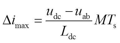 (11)
(11)
由式(10)、式(11)对比可知,电感两端的最大电压差由原来的udc减小为udc-uab,从而能在不增大电感值和开关频率下减小直流链电流的纹波。
其他扇区均按上述方法优化,具体的一个周期内DC-DC变换器与CSI协同控制如图6所示。DC-DC变换器由计算出的电压调制比以固定脉冲作用,而在计算出CSI的电流矢量作用时间后,比较两个有效电流矢量I1、I2对应输入电压u1、u2的大小,使电流矢量按照输入电压由小到大的顺序作用,从而使DC-DC变换器输出udc的时间段与具有较大输入电压的电流矢量重叠,减小电感两端的电压差从而减小纹波。
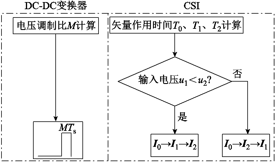
图6 一个周期内DC-DC变换器与CSI协同控制图
Fig.6 Cooperative control of DC-DC converter and CSI in one cycle
对于五段式或七段式SVPWM,本文所提的通过优化电流矢量序列减小电感两端电压差而抑制纹波的方法依然可行,但其实现变得略为复杂。由于五段式或七段式拆分了部分电流矢量,因此DC-DC变换器在一个周期内输出udc的时间段也需要相应拆分。以五段式为例,图7所示为优化前后的电流纹波。优化后,一个周期中的后半周期,电流矢量按照输入电压由小到大顺序作用,DC-DC变换器输出udc的一半时间段与具有较大输入电压的电流矢量重叠,这样电感两端的电压差能达到最小,从而纹波最小。虽然更多段式的调制方法可以降低纹波,但是却会导致更多的开关换相和损耗,因此本文选用了三段式。
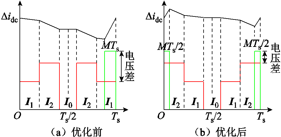
图7 五段式SVPWM优化前后电流纹波
Fig.7 Current ripple before and after optimization of five segments SVPWM
为了验证所提方法的可行性与正确性,搭建了如图8所示的三相CSI永磁同步电机实验平台。其中,直流电机提供负载,驱动器控制芯片型号为TI公司TMS320F28377。表2为电机驱动系统实验参数。

图8 CSI电机驱动系统实验平台
Fig.8 Experiment platform of CSI motor drive system
表2 电机驱动系统实验参数
Tab.2 Experimental parameters of motor drive system
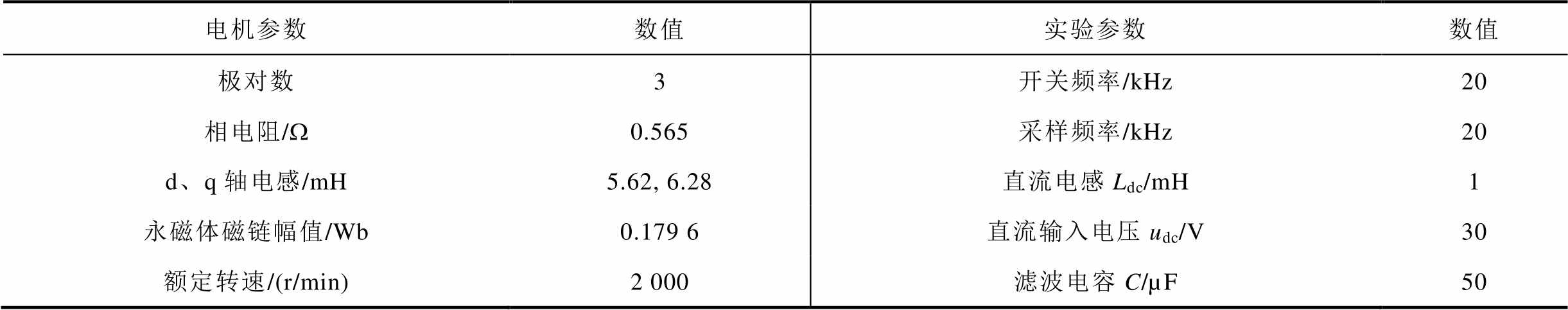
电机参数数值实验参数数值 极对数3开关频率/kHz20 相电阻/W0.565采样频率/kHz20 d、q轴电感/mH5.62, 6.28直流电感Ldc/mH1 永磁体磁链幅值/Wb0.179 6直流输入电压udc/V30 额定转速/(r/min)2 000滤波电容C/µF50
首先,为了验证本文设计的PI控制器能够实现直流链电流控制,设定直流链电流给定值为6 A,电机转速设为200 r/min,测量永磁同步电机在起动阶段直流链电流变化如图9所示。由实验结果可以看出,在电机起动后,直流链电流虽然出现了一定的超调,但很快能够稳定在给定值,说明了所设计的PI控制器能够实现直流链电流控制。
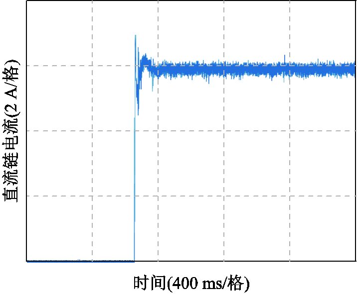
图9 PMSM起动阶段直流链电流
Fig.9 The DC-link current of PMSM at starting phase
为了验证直流链电流控制的动态特性,进行了转速突变实验,转速由100 r/min突变为200 r/min。由于所搭平台为直流电机接功率电阻,因此在转速增大时负载转矩也相应增大。图10所示是转速及直流链电流波形。由图10可知,在转速与负载转矩同时增大时,直流链电流虽然稍有波动,但依然能快速稳定在给定值,因此,本文提出的直流侧直流链电流控制方法具有良好的动态性。此外,对纹波抑制前后,转速切换时的直流链电流进行对比实验,结果如图11所示。由图11可以看出,优化前后直流链电流具有相似的动态性能。因此,本文提出的直流链电流纹波抑制方法不影响直流侧的动态性能。
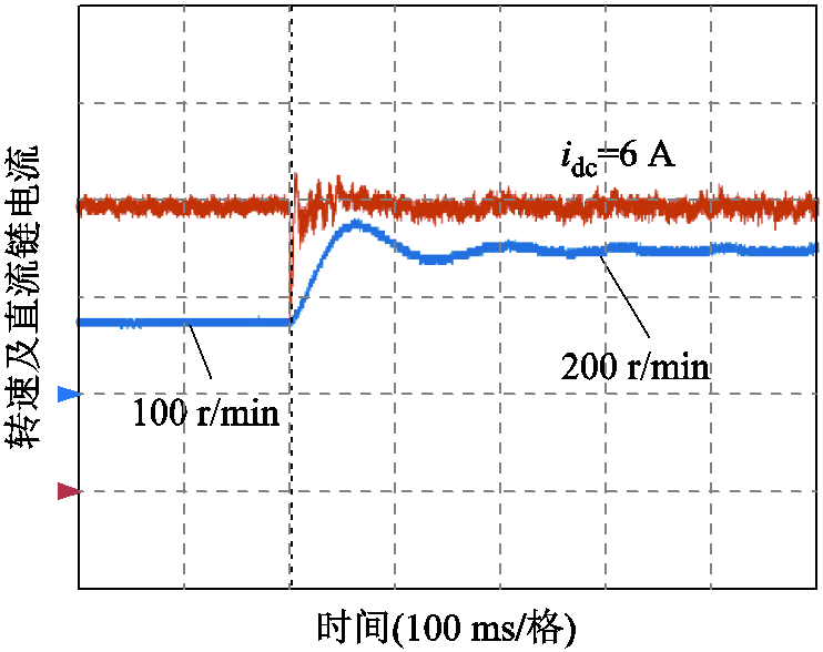
图10 转速及直流链电流波形
Fig.10 Waveforms of speed and DC-link current
为了验证DC-DC变换器的电压调制比M为定值,当电机运行在200 r/min时,将DC-DC变换器的电压调制比M经D-A转换输出到示波器进行观察,并对开关管Sd的开关信号进行测量。图12所示是DC-DC变换器电压调制比变化的实验结果。由图12可知,电压调制比M稳定在0.43附近。图13为开关管Sd的开关信号,同样计算出电压调制比M=22 μs/50 μs=0.44。由以上实验结果可知,当电机在稳态运行时,DC-DC变换器电压调制比M为定值,与理论分析一致。
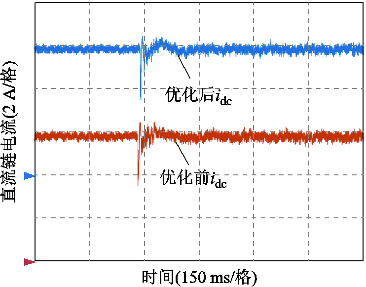
图11 优化前后直流链电流波形
Fig.11 Waveforms of DC-link current before and after optimization
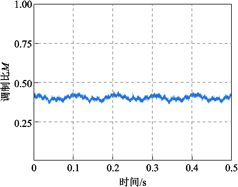
图12 DC-DC变换器电压调制比变化的实验结果
Fig.12 Experimental results of voltage modulation ratio variation of DC-DC converter
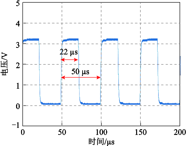
图13 开关管Sd的开关信号
Fig.13 Switching signals of the switching tube Sd
为了验证直流链电流纹波抑制的有效性,设定直流链电流为6 A,电机转速为50 r/min和200 r/min,分别测量直流链电流纹波在优化前后的波形如图14和图15所示。由图14和图15的实验结果可以看出,在50 r/min时,直流链电流纹波的峰-峰值由优化前的210 mA减小为150 mA。在200 r/min时,直流链电流纹波的峰-峰值由优化前的400 mA减小为200 mA。与此同时对电机的相电流和谐波含量进行分析,实验结果如图16和图17所示。在50 r/min时,总谐波畸变率(Total Harmonic Distortion, THD)由优化前的12.54%减小为11.75%。在200 r/min时,总谐波畸变率(THD)由优化前的7.76%减小为6.53%。以上实验结果均验证了所提直流链电流纹波抑制方法的正确性。
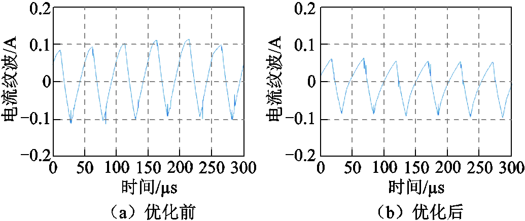
图14 50 r/min时直流链电流纹波优化前后波形
Fig.14 Waveform of DC-link current ripple before and after optimization at 50 r/min
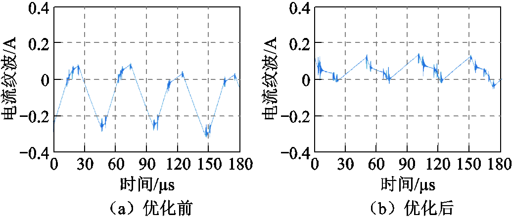
图15 200 r/min时直流链电流纹波优化前后波形
Fig.15 Waveform of DC-link current ripple before and after optimization at 200 r/min
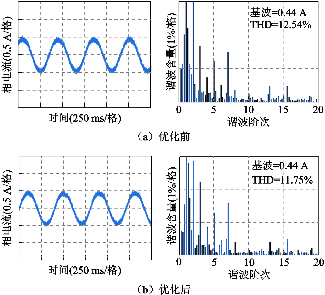
图16 50 r/min时优化前后相电流与谐波含量实验结果
Fig.16 Experimental results of phase current and harmonic content before and after optimization at 50 r/min
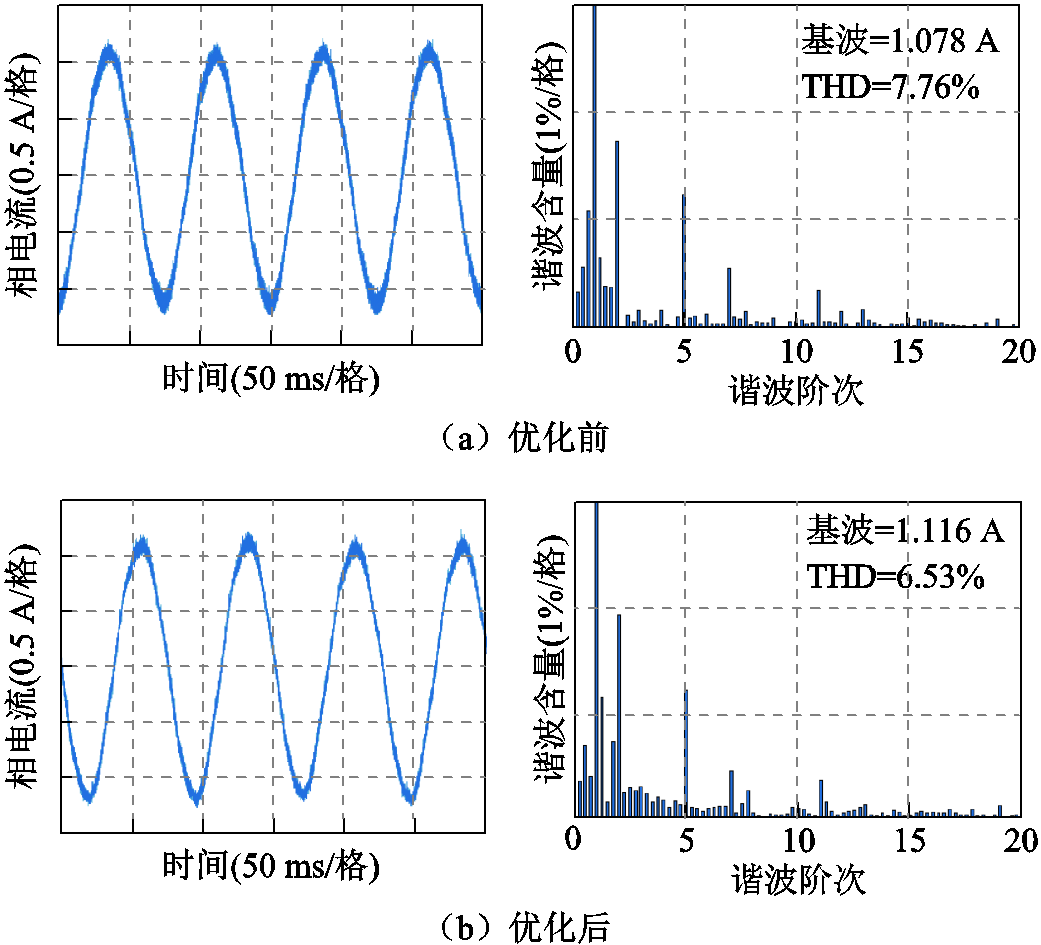
图17 200 r/min时优化前后相电流与谐波含量实验结果
Fig.17 Experimental results of phase current and harmonic content before and after optimization at 200 r/min
此外,将本文由DC-DC变换器电路设计的CSI系统的直流链电流纹波抑制方法与其他类型电流源的直流链电流纹波抑制方法进行对比。文献[19]针对背靠背型电流源变换器,对三段式SVPWM进行分析,通过协调整流器和逆变器的矢量顺序,减小电感两端电压差进而减小直流链电流纹波,根据其文中实验结果可以看出,电流纹波得到显著减小。但是该方法不能提升输出电流波形质量。因此,文献[19]所提方法在减小直流链电流纹波的同时不影响输出电流质量。文献[20]针对电流源型整流器,对五段式SVPWM进行分析,根据不同的系统调制比,通过替换零矢量或非零矢量的方法来减小电压差进而减小直流链电流纹波,其实验结果表明,直流链电流纹波得到显著改善,但输出电流质量却变差,尤其在低调制比时,需要采用占空比补偿等其他方法来抑制因扇区过渡造成的电流畸变。将本文所提方法与上述两种方法总结见表3。通过比较可知,本文所提的直流链电流纹波抑制方法算法简单,适用于三、五、七段式SVPWM,能够提高输出电流质量。
表3 直流链电流纹波抑制方法比较
Tab.3 Comparison of DC-link current ripple suppression methods

项目所提方法文献[19]方法文献[20]方法 算法复杂度简单简单一般 适用调制方式三、五、七段式三段式五段式 输出谐波性能提升不变降低
本文提出了一种针对CSI电机驱动系统的直流链电流控制方法。该方法采用DC-DC变换器电路并使用PI控制器实现对直流链电流的控制,在分析了一个周期内DC-DC变换器与CSI的电压变化规律后,通过优化CSI的电流矢量序列,减小了直流链电流纹波。搭建了实验平台,开展了实验验证。实验结果表明,采用提出的直流链电流控制方法,能够实现对直流链电流的控制,减小直流链电流的纹波,从而减小了电感损耗和开关损耗,提高了交流侧电机的电流波形质量。
参考文献
[1] Akbar F, Cha H, Do D T. CSI7: novel three-phase current-source inverter with improved reliability[J]. IEEE Transactions on Power Electronics, 2021, 36(8): 9170-9182.
[2] 黄林森, 赵文祥, 吉敬华, 等. 稳态性能改善的双三相永磁电机直接转矩控制[J]. 电工技术学报, 2022, 37(2): 355-367. Huang Linsen, Zhao Wenxiang, Ji Jinghua, et al. Direct torque control for dual three-phase permanent-magnet machine with improved steady-state performance[J]. Transactions of China Electrotechnical Society, 2022, 37(2): 355-367.
[3] 贺虎成, 刘卫国, 李榕, 等. 电机驱动用新型谐振直流环节电压源逆变器[J]. 中国电机工程学报, 2008, 28(12): 60-65.He Hucheng, Liu Weiguo, Li Rong, et al. A novel resonant DC link voltage source inverter for motor drives[J]. Proceedings of the CSEE, 2008, 28(12): 60-65.
[4] 韩应生, 孙海顺, 秦世耀, 等. 电压源型双馈风电并网系统小扰动低频稳定性分析[J]. 电工技术学报, 2023, 38(5): 1312-1324, 1374. Han Yingsheng, Sun Haishun, Qin Shiyao, et al. Low-frequency stability analysis of voltage-sourced doubly-fed wind power grid-connected system under small disturbance[J]. Transactions of China Electrotechnical Society, 2023, 38(5): 1312-1324, 1374.
[5] Song Yantao, Wang Bingsen. Survey on reliability of power electronic systems[J]. IEEE Transactions on Power Electronics, 2013, 28(1): 591-604.
[6] Guo Xiaoqiang, Sui Sen, Wang Baocheng, et al. A current-based approach for short-circuit fault diagnosis in closed-loop current source inverter[J]. IEEE Transactions on Industrial Electronics, 2020, 67(9): 7941-7950.
[7] Guzman J I, Espinoza J R, Zargari N R, et al. Selective harmonic elimination in multi-modules three-phase current-source converters[C]//2006 IEEE International Symposium on Industrial Electronics, Montreal, QC, Canada, 2007: 1241-1246.
[8] Zhang Yichao, Jahns T M. Uncontrolled generator operation of PM synchronous machine drive with current-source inverter using normally on switches[J]. IEEE Transactions on Industry Applications, 2017, 53(1): 203-211.
[9] 苗轶如, 刘和平, 华泽玺, 等. 基于直流侧储能电感电流最优给定的三相电流源型逆变器控制策略[J].电工技术学报, 2019, 34(2): 349-362. Miao Yiru, Liu Heping, Hua Zexi, et al. Control strategy for three-phase current source inverter based on optimal given value of DC storage inductance current[J]. Transactions of China Electrotechnical Society, 2019, 34(2): 349-362.
[10] 王晓琳, 郭慧, 顾聪. 一种基于电流源逆变驱动的超高速永磁同步电机改进型控制策略[J]. 中国电机工程学报, 2022, 42(7): 2733-2744. Wang Xiaolin, Guo Hui, Gu Cong. An improved control strategy for the ultra-high-speed permanent magnet synchronous motor based on the current source inverter[J]. Proceedings of the CSEE, 2022, 42(7): 2733-2744.
[11] Migliazza G, Buticchi G, Carfagna E, et al. DC current control for a single-stage current source inverter in motor drive application[J]. IEEE Transactions on Power Electronics, 2021, 36(3): 3367-3376.
[12] Xu Yang, Wang Zheng, Liu Pengcheng, et al. A soft-switching current-source-inverter-fed motor drive with reduced common-mode voltage[J]. IEEE Trans-actions on Industrial Electronics, 2021, 68(4): 3012-3021.
[13] Lee H J, Jung S, Sul S K. A current controller design for current source inverter-fed AC machine drive system[J]. IEEE Transactions on Power Electronics, 2013, 28(3): 1366-1381.
[14] 陈亦文, 邱琰辉, 何勇吉, 等. 储能电感电流限定单周期控制单相电流型PWM逆变器研究[J]. 电工技术学报, 2015, 30(14): 311-319. Chen Yiwen, Qiu Yanhui, He Yongji, et al. Research on single-phase current mode PWM inverter of one-cycle control strategy with limited storage inductance current[J]. Transactions of China Electrotechnical Society, 2015, 30(14): 311-319.
[15] Su Guijia, Tang Lixin. Current source inverter based traction drive for EV battery charging applications[C]// 2011 IEEE Vehicle Power and Propulsion Conference, Chicago, IL, USA, 2011: 1-6.
[16] Zhang Ye, Li Yun wei. Investigation and suppression of harmonics interaction in high-power PWM current-source motor drives[J]. IEEE Transactions on Power Electronics, 2015, 30(2): 668-679.
[17] Li Yun wei, Pande M, Zargari N, et al. DC link current minimization for high power current source motor drives[C]//2008 IEEE Power Electronics Specialists Conference, Rhodes, Greece, 2008: 2505-2511.
[18] Guo Xiaoqiang, Xu D, Wu Bin. Common-mode voltage mitigation for back-to-back current-source converter with optimal space-vector modulation[J]. IEEETransactions on Power Electronics, 2016, 31(1): 688-697.
[19] Guo Xiaoqiang, Xu D, Guerrero J M, et al. Space vector modulation for DC-link current ripple reduction in back-to-back current-source converters for microgrid applications[J]. IEEE Transactions on Industrial Electronics, 2015, 62(10): 6008-6013.
[20] 肖蕙蕙, 周琛力, 郭强, 等. 用于改善直流链电流纹波的电流源型整流器扇区优化调制策略[J]. 电工技术学报, 2021, 36(24): 5250-5260. Xiao Huihui, Zhou Chenli, Guo Qiang, et al. Optimized sector modulation strategy of current source rectifier for DC-link current ripple reduction[J]. Transactions of China Electrotechnical Society, 2021, 36(24): 5250-5260.
[21] Cuzner R M, Venkataramanan G. Current source rectifiers in discontinuous conduction modes of operation[J]. IEEE Transactions on Industry Applica-tions, 2015, 51(1): 470-478.
Abstract Motor drive system can be divided into voltage source inverter(VSI) topology and current source inverter (CSI) topology according to the type of DC side power supply.Compared with VSI, CSI uses inductance as energy storage element, which has high reliability. At the same time, CSI also has the advantages of high output current waveform quality, can realize four quadrant operation of motor load, inherent short circuit protection function and voltage boost function to expand the constant power operation range of motor. However, the DC-link current is not controlled in this way, and the DC-link current will be intermittent or continuously increased. Therefore, a PI controller is designed by using DC-DC converter circuit to control DC-link current. At the same time, the ripple of DC-link current is suppressed by optimizing the current vector sequence of CSI, the inductance and switching loss are reduced, and the current waveform quality of the motor at the output end is improved.
Firstly,in order to realize the control of DC-link current, a DC-DC converter circuit is adopted on the basis of the traditional current source inverter circuit. Through the analysis of different working modes of DC-DC converter, two working modes are selected to realize the control of DC-link current, and the field oriented control of CSI motor drive systemis designed.Secondly, the analysis of the DC-link current ripple of CSI system shows that in order to reduce the DC-link current ripple, the voltage difference between the two ends of the inductance should be reduced without increasing the inductance value and the switching frequency. Therefore, by analyzing the output voltage of DC-DC converter and the input voltage of CSI in a cycle in detail, we can know the voltage difference between the two ends of the inductance. Finally, according to the variation regularity of voltage between the DC-DC converter and CSI in one cycle, a method to optimize CSI current vector sequence is proposed.The feasibility of the method is illustrated through the specific analysis of the three segment SVPWM modulation method, and the feasibility of other more segment modulation methods is analyzed. The method proposed in this paper is tested. By observing the DC-link current in the startup stage and the speed change stage, it can be seen that the DC-link current can be controlled by the DC-DC converter circuit in this paper, and it has good dynamics. The current ripple suppression method does not change the dynamics of the DC side. The experiments of DC-link current ripple suppression at different speeds show that the ripple of DC-link current is reduced. At the same time, the harmonic analysis of the output current is carried out, and the total harmonic distortion of the output current is reduced by using the proposed DC-link current ripple suppression method, which proves the effectiveness of the proposed DC-link current ripple suppression method.
Therefore, the following conclusions can be drawn. This paper presents a DC-link current control method for CSI motor drive system. The method uses DC-DC converter circuit and PI controller to control the DC-link current. After analyzing the voltage variation rule between DC-DC converter and CSI in one cycle, the DC-link current ripple is reduced by optimizing the current vector sequence of CSI. The experimental platform was built and the experimental verification was carried out. The experimental results show that the proposed DC-link current control method can realize the control of DC-link current, reduce the ripple of DC-link current, thus reduce the inductance loss and switching loss, and improve the quality of the current waveform of the motor.
keywords:Current source inverter, DC-link current, current vector sequence, DC-link current ripple
DOI:10.19595/j.cnki.1000-6753.tces.221716
中图分类号:TM464; TM315
国家杰出青年科学基金资助项目(52025073)。
收稿日期 2022-09-07
改稿日期 2022-11-29
赵文祥 男,1976年生,教授,博士生导师,研究方向为电机及其控制。E-mail:zwx@ujs.edu.cn(通信作者)
周书文 男,1990年生,硕士,研究方向为永磁电机的驱动控制。E-mail:670964117@qq.com
(编辑 郭丽军)