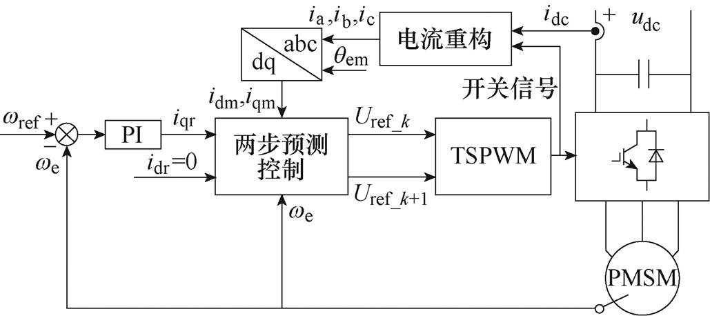
图1 单母线电流传感器驱动系统框图
Fig.1 Block diagram of single DC-link current sensor drive
摘要 该文研究基于单母线电流传感器的三相永磁同步电机驱动方法,无需使用相电流传感器而是通过单母线电流传感器重构三相电流信号,为消除母线电流传感器重构死区的影响,提出基于两步预测控制的三态脉宽调制方法,利用3个相邻的开关状态构建参考电压,通过两步预测计算下一个周期的参考电压,避免了逆变器多相桥臂同时动作。所提出的单母线电流传感器驱动方法具有共模电压峰-峰值低、电流谐波含量小、采样点固定的优点。最后,通过实验验证了重构电流的准确性和所提出驱动方法的有效性。
关键词:永磁同步电机 母线电流传感器 预测控制 重构电流 三态脉宽调制
永磁同步电机(Permanent Magnet Synchronous Machine, PMSM)具有功率密度高、效率高、可靠性好、动态响应快等优点,被广泛应用于伺服驱动、轨道交通、新能源发电等领域[1-3]。PMSM驱动系统需要准确的定子电流信息来实现高精度、高动态的运动控制,通常三相PMSM驱动系统至少需要安装两个相电流传感器来获取准确的定子电流信号。但是,在恶劣的工作环境中,电流传感器容易产生各种故障或受到噪声干扰的影响,导致采集的电流信号不够准确。不准确的定子电流反馈会导致驱动系统控制性能恶化,解决该问题的一种方法是减少驱动系统中的电流传感器数量,如采用单母线电流传感器驱动[4]。此外,采用单母线电流传感器的驱动,还可以降低系统成本、缩减装置体积。
近年来,单母线电流传感器驱动受到了学术界广泛的关注。文献[5-7]提出逆变器不同开关状态下母线电流与定子电流的串联效应,使用母线测量电流信号和逆变器开关状态重构定子电流,并将重构定子电流作为反馈输入驱动系统实现单母线电流传感器控制,但是使用传统的空间矢量脉宽调制(Space Vector Pulse Width Modulation, SVPWM)参考电压时,这种方法存在重构死区的问题,如果输入SVPWM的参考电压位于重构死区,SVPWM计算得到的有源电压矢量作用时间将会小于最小采样时间,导致母线电流传感器无法准确重构定子电流,重构方法失效。文献[8-11]在SVPWM过程中插入测量矢量来消除重构死区的影响,实现定子电流的有效重构,但这种方法增加了逆变器开关次数与开关损耗,并且在参考电压幅值较低时会造成大量定子电流谐波,影响系统运行性能。文献[12-17]提出一种SVPWM信号移相方法,当参考电压位于重构死区时,平移SVPWM输出开关信号波形,延长有源电压矢量作用时间,但这种方法可能出现移相后有源电压矢量作用时间仍小于最小采样时间的情况,无法彻底解决重构死区问题。文献[18-19]提出一种在零电压矢量作用时进行电流采样的方法,将重构死区从电压矢量六边形的内部移向边缘,这种方法在保持SVPWM输出开关信号不变的同时,避免了开关次数增加并消除了重构死区的影响,但这种方法需要使用电流传感器测量两条电路的电流之和,传感器安装方式复杂。文献[20]提出一种不使用零矢量的调制方法,仅使用有源电压矢量调制电压并消除重构死区的影响,但在低电压调制时这种方法会在系统中引入大量谐波,降低系统运行性能。文献[21]提出一种三态脉宽调制(Tristate Pulse Width Modulation, TSPWM)方法,使用3个相邻的有源电压矢量调制得到五段式TSPWM开关信号并消除重构死区的影响,但这种方法需要逆变器多相桥臂同时动作,容易对系统造成干扰,降低驱动控制性能。
本文提出一种基于单母线电流传感器的三相永磁同步电机驱动方法,使用TSPWM有效消除重构死区的影响,使用两步预测控制获得当前周期与下一周期的参考电压并以此为依据选择合适的TSPWM始末电压矢量,避免了逆变器多相开关同时动作。所提出的单母线电流传感器驱动方法具有共模电压峰-峰值低、电流谐波含量小、电流传感器采样点固定的优点。最后搭建了实验平台并通过实验验证了重构电流的准确性和驱动方法的有效性。
图1为所提出基于单母线电流传感器的三相PMSM驱动系统框图。该驱动系统使用PI调节器控制电机转速,使用母线电流信号以及逆变器开关状态重构定子电流作为电流反馈,使用令d轴给定电流为零的两步模型预测控制获取当前周期及下一周期的参考电压,随后TSPWM根据这两组参考电压选择恰当的始末电压矢量调制当前周期的参考 电压。

图1 单母线电流传感器驱动系统框图
Fig.1 Block diagram of single DC-link current sensor drive
图2为由三相电压源逆变器(Voltage Source Inverter, VSI)驱动的三相交流系统。图2中,N为负载中性点,O为母线侧中点,idc和udc分别为母线电流和电压。三相负载相对于O的电压分别为va、vb、vc,它们的平均值被定义为共模电压(Common Mode Voltage, CMV)[22]。
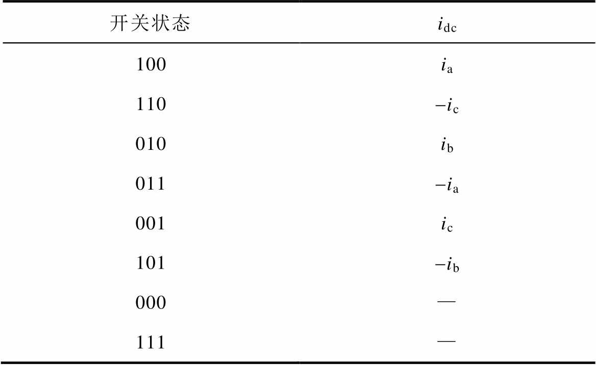
母线电流传感器重构定子电流信号的原理是母线电流的串联效应,表1为逆变器八种开关状态下母线电流与相电流间的关系,根据逆变器的不同开关状态,可以将测得的母线电流分配到各相,实现定子电流的重构。在七段式的SVPWM中,每个周期有两个不同的有源电压矢量和两个零矢量作用,根据表1,母线电流传感器可以测得两相定子电流,剩余一相电流可以根据基尔霍夫定律计算获得。
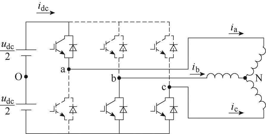
图2 三相电压源逆变器驱动交流系统结构
Fig.2 Three-phase VSI-driven AC system structure
表1 不同开关状态下相电流与母线电流间的关系
Tab.1 Relationship between phase current and DC-link current in different switching states
开关状态idc 100ia 110-ic 010ib 011-ia 001ic 101-ib 000— 111—
实际应用中,电流的采集需要一定时间,将能采集到准确电流信息所需的最短时间定义为最小采集时间Tmin,定义为
 (1)
(1)
式中,Tdead为逆变器死区时间;Tset为电流完全建立所需时间;Tmea为测量电流信号转换到数字信号所需要的时间。当有源电压矢量作用时间过短时,母线电流传感器无法采集到准确的电流信息,此时定子重构方法失效。七段式的SVPWM的电流重构死区如图3a所示。
与传统的模型预测控制方法不同,在第k个周期时两步预测控制不计算当前周期作用的电压矢量Uref_k=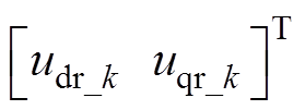 ,而是计算第k+1个周期时作用电压Uref_k+1=
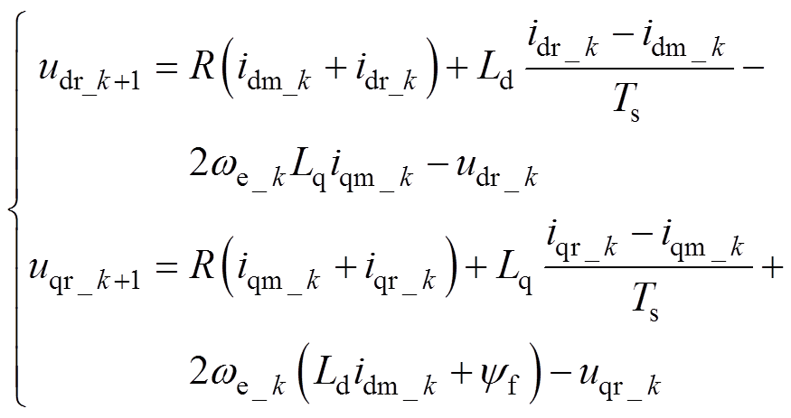
 。第k个周期时作用的两步预测控制计算为
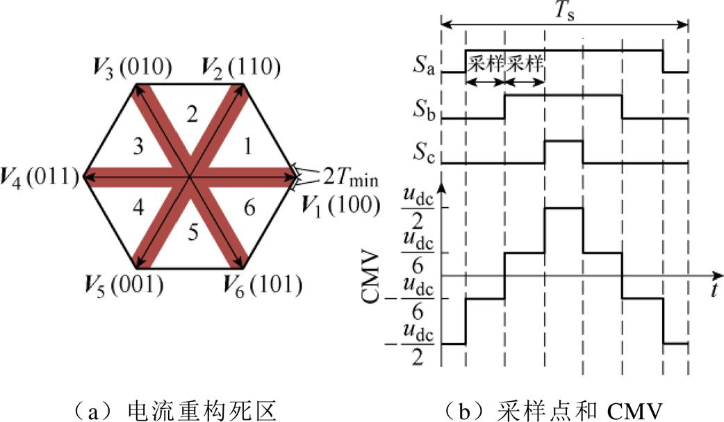
图3 传统SVPWM的重构死区
Fig.3 Dead zone of conventional SVPWM
 (2)
(2)
式中,R为PMSM定子电阻;Ld、Lq分别为PMSM在d、q坐标系下的电感;yf为永磁体磁链;idm和iqm分别为d、q坐标系下的测量电流;idr和iqr分别为d、q坐标系下的给定电流;we为电机电角速度;Ts为计算步长。
图4为两步预测控制中计算和调制参考电压的时序。通过两步预测控制,控制系统在第k个周期时可以同时获得当前周期作用电压Uref_k和下一周期作用电压Uref_k+1。
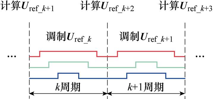
图4 两步预测控制中计算和调制参考电压时序
Fig.4 Sequence of reference voltage calculation and modulation in two-step predictive control
1.3.1 基于两步预测控制的TSPWM原理
将图4中所示SVPWM电压平面的扇区顺时针旋转30 °即可获得TSPWM电压空间平面,如图5所示。TSPWM扇区2中的电压调制如图6所示,TSPWM使用最多3个有源电压矢量调制参考电压,如果参考电压位于高电压区域,TSPWM使用Vleft、Vright和Vmid 3个有源电压矢量调制参考电压;如果参考电压位于低电压区域,TSPWM只使用Vleft和Vright调制参考电压。其中,Tleft、Tright和Tmid分别为Vleft、Vright和Vmid的作用时间,并且如果参考电压位于高电压区域,Tleft、Tright和Tmid满足
 (3)
(3)
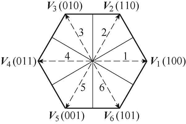
图5 TSPWM电压空间平面
Fig.5 Voltage space of TSPWM
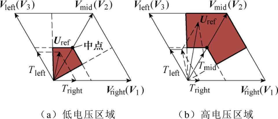
图6 TSPWM扇区2中的电压调制
Fig.6 Voltage modulation in sector 2 of TSPWM
图7和图8展示了在TSPWM扇区2中两种电压调制方法的开关顺序和电机共模电压波形,其中图7以V1为始末电压矢量,图8以V3为始末电压矢量。文献[22]中指出,对驱动系统造成危害最大的是CMV峰-峰值而不是CMV的幅值,与图3b所示的传统七段式SVPWM相比,TSPWM的CMV幅值不变而峰-峰值更小,在一个周期内仅为SVPWM的1/3,并且波动频率更低,因此TSPWM能够有效降低CMV给系统带来的危害。
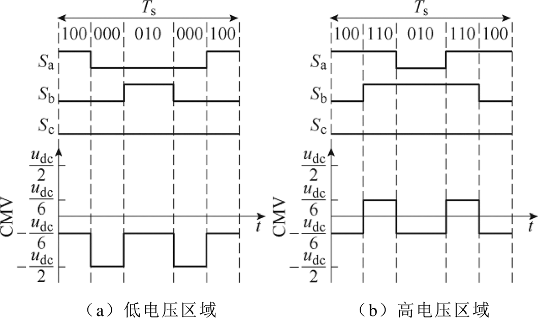
图7 TSPWM扇区2中的电压调制开关顺序与CMV(V1为始末电压矢量)
Fig.7 Voltage modulation switching sequence and CMV in sector 2 of TSPWM (V1 is the head and tail voltage vector)
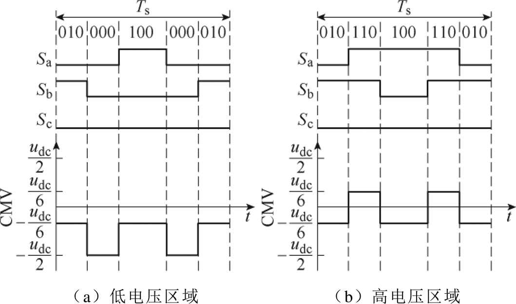
图8 TSPWM扇区2中的电压调制开关顺序与CMV(V3为始末电压矢量)
Fig.8 Voltage modulation switching sequence and CMV in sector 2 of TSPWM (V3 is the head and tail voltage vector)
从图7和图8中可以看出,TSPWM能够选择Vright和Vleft中任意一个电压矢量作为始末电压矢量进行调制,TSPWM各个扇区中的可选始末电压矢量见表2。
表2 TSPWM各扇区中可选始末矢量
Tab.2 Optional head and tail vectors in each sector of TSPWM
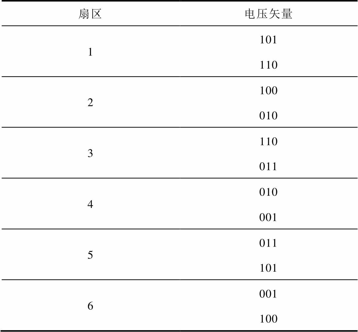
扇区电压矢量 1101110 2100010 3110011 4010001 5011101 6001100
TSPWM扇区2→扇区4的电压调制开关顺序与CMV如图9所示。如图9a所示,假设TSPWM在调制扇区2中的参考电压时选择了V1(100)作为始末电压矢量,并且下一周期的参考电压位于扇区4,那么TSPWM无论如何选择下一周期的始末矢量,都无法避免逆变器多相桥臂同时动作(100→010、100→001)。实际应用中各相桥臂的开关管无法做到完全同步动作,多相桥臂的同时动作会给系统带来额外的干扰,不利于驱动系统稳定运行,文献[21]便遇到了多相桥臂同时动作的情况,导致电流谐波含量增大,系统驱动性能下降。但是如果TSPWM在调制扇区2中的参考电压时选择了V3(010)作为始末电压矢量,那么TSPWM在调制扇区4内的参考电压时无需进行任何额外开关动作,如图9b所示。两步预测控制可以获得当前周期与下一周期的参考电压,根据这两个参考电压,TSPWM可以在当前周期选择合适的始末电压矢量来避免多相桥臂同时动作。TSPWM扇区2中参考电压调制的始末矢量选择和下一周期参考电压所在扇区的关系见表3,其他扇区的始末矢量选择可以以此类推。
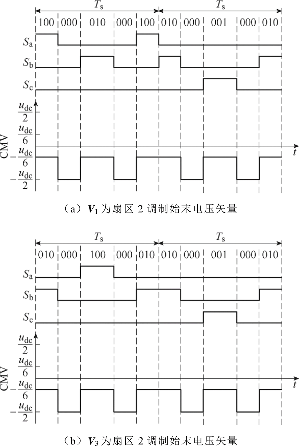
图9 TSPWM扇区2→扇区4的电压调制开关顺序与CMV
Fig.9 Voltage modulation switching sequence and CMV from sector 2 to 4 of TSPWM
如果当前周期参考电压调制的始末电压已经在上一周期决定,此时TSPWM无法选择合适的始末矢量,可能会导致多相桥臂同时动作。例如,参考电压所在扇区的顺序为扇区2→扇区4→扇区6时,扇区4内参考电压调制的始末电压矢量被限制为010,TSPWM在调制扇区6内的参考电压时需要进行010→001或010→100的多相桥臂动作。为解决这一问题,在扇区4的电压调制末尾插入一段零矢量000,即可在不影响电压调制准确性的前提下实现开关状态的平滑切换,如图10所示。
表3 TSPWM扇区2中始末电压矢量选择逻辑
Tab.3 Selection logic of head and tail voltage vector in section 2 of TSPWM
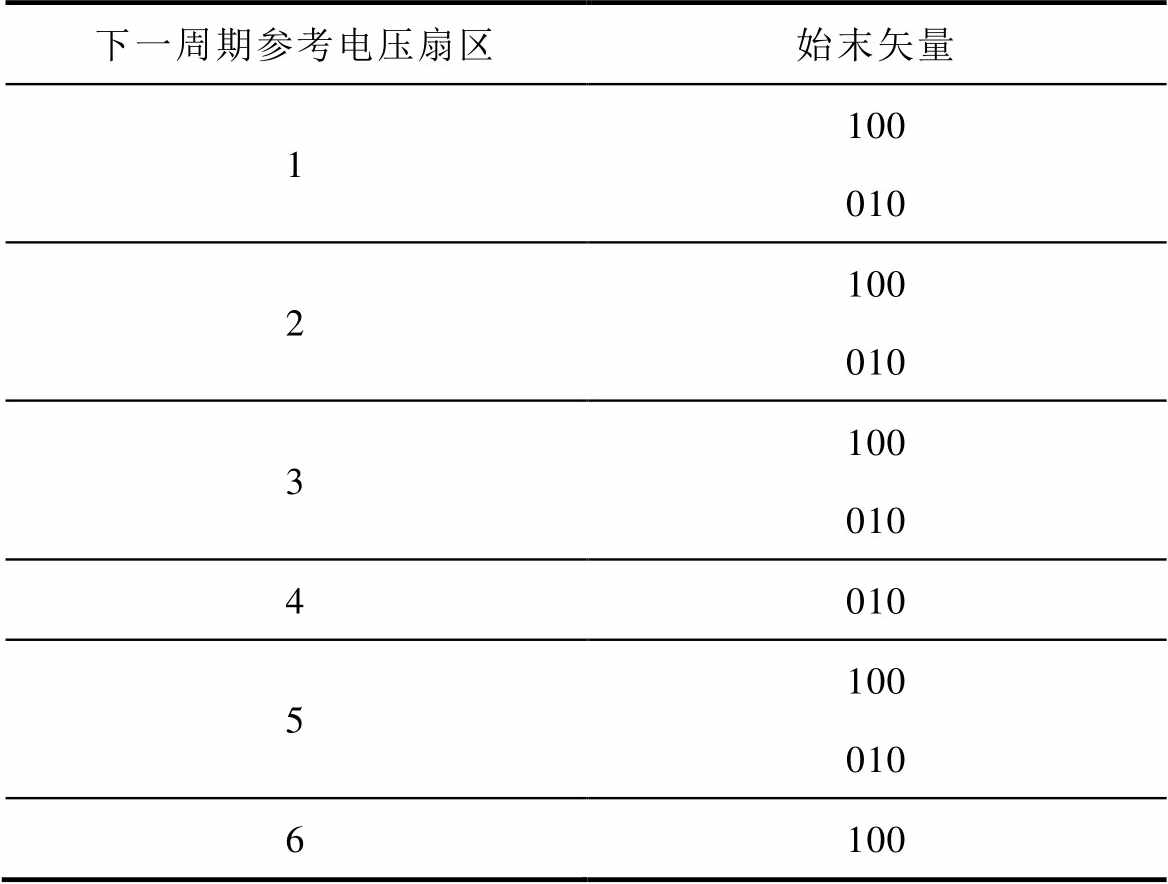
下一周期参考电压扇区始末矢量 1100010 2100010 3100010 4010 5100010 6100
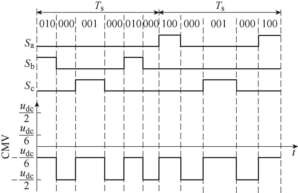
图10 TSPWM扇区2→扇区4插入零电压矢量后的调制开关顺序与CMV
Fig.10 Voltage modulation switching sequence and CMV from sector 2 to 4 of TSPWM with zero voltage vector inserted
虽然插入了一段零矢量会使得TSPWM过程变得不对称,但是该零矢量作用时间很短。此外,根据表2可以看出,当始末电压矢量被限制为010并且下个周期参考电压位于扇区6中时,TSPWM才需要插入零矢量实现开关状态的平滑切换,零矢量的插入频率较低,因此是可以接受的。
1.3.2 TSPWM重构死区
图11、图12分别为参考电压位于扇区2低、高电压区域时的母线电流采样点。可以看出,电流采样点分布在TSPWM周期的两端和中间,因此与其他单母线电流传感器驱动方法不同,所提出的驱动方法不需要额外计算采样点位置。图11、图12中没有考虑插入的零矢量(见图10),因为该零矢量作用时间很短,对采样点位置影响很小。

图11 扇区2低电压区域中的母线电流采样点
Fig.11 DC-link current sampling point in low voltage of section 2

图12 扇区2高电压区域中的母线电流采样点
Fig.12 DC-link current sampling point in high voltage of section 2
TSPWM电流重构死区如图13所示。当Tright/2<Tmin或Tleft/2<Tmin时,母线电流传感器无法有效测得对应相电流,该区域即为TSPWM重构死区,如图13a所示。
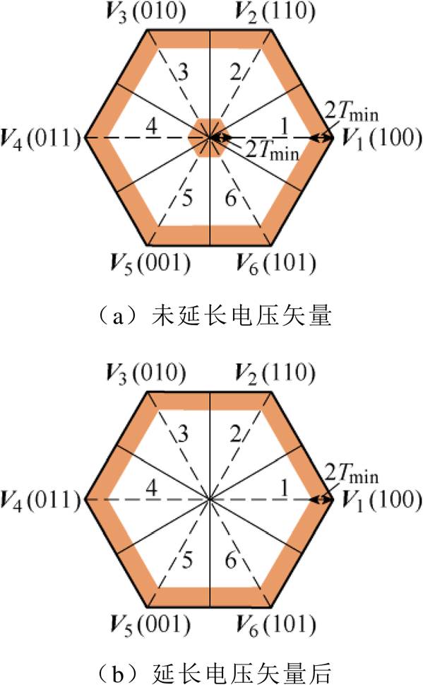
图13 TSPWM电流重构死区
Fig.13 TSPWM dead zone of current reconstruction
低电压区域的重构死区(见图13中心阴影部分)可以通过延长Vleft和Vright的作用时间消除,图14为延长电压矢量前后扇区2中的参考电压调制开关顺序,其中虚线是延长前的状态,实线是延长后的状态。
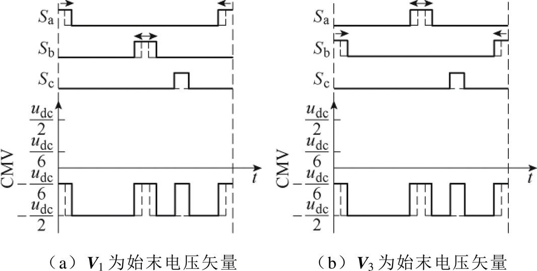
图14 延长矢量后扇区2的电压调制开关顺序与CMV
Fig.14 Voltage modulation switching sequence and CMV in sector 2 with extended vectors
从图14中可以看出,延长电压矢量后CMV峰-峰值并未增大,虽然增加了CMV的波动频率,但仍然低于传统七段SVPWM。延长电压矢量后的TSPWM重构死区如图13b所示,当Ts=100 ms,Tmin=8 ms时,TSPWM重构死区面积约为SVPWM重构死区面积的54 %,并且重构死区全部位于扇区边缘,因此所提出的方法能够有效消除重构死区的影响。
为了验证该基于母线电流传感器的三相PMSM驱动方法的有效性,在Matlab/Simulink平台上进行了仿真验证,电机仿真参数见表4,逆变器母线侧电压udc=311 V,控制周期Ts设为100 ms,最小采集时间Tmin设为8 ms。
表4 永磁同步电机参数
Tab.4 Parameters of PMSM
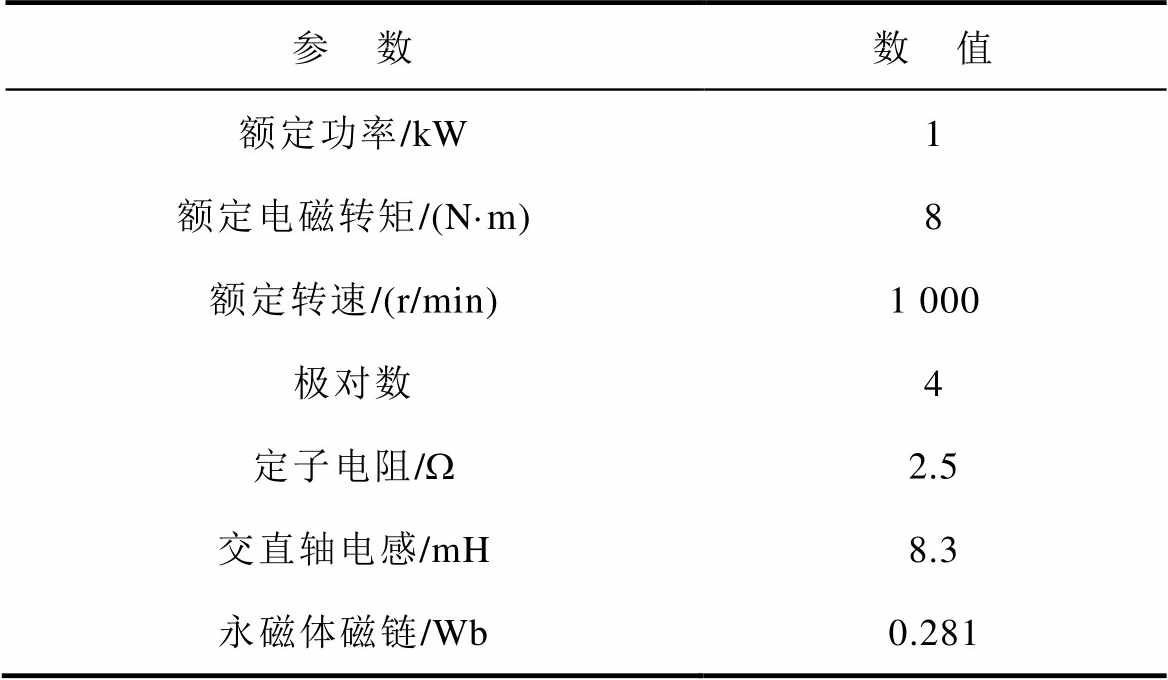
参 数数 值 额定功率/kW1 额定电磁转矩/(N·m)8 额定转速/(r/min)1 000 极对数4 定子电阻/W2.5 交直轴电感/mH8.3 永磁体磁链/Wb0.281
2.1.1 电流重构仿真结果
图15、图16分别为PMSM转速和负载发生变化时重构a相电流的仿真结果。图15中的电机负载设为4 N·m,电机转速由100 r/min增加至600 r/min。图16中的电机给定转速为400 r/min,设置负载从0.5 N·m增加至6 N·m。可以看出,重构电流与测量电流之间的误差较小,证明了该电流重构方法在暂态和稳态时均具有较高的准确性。
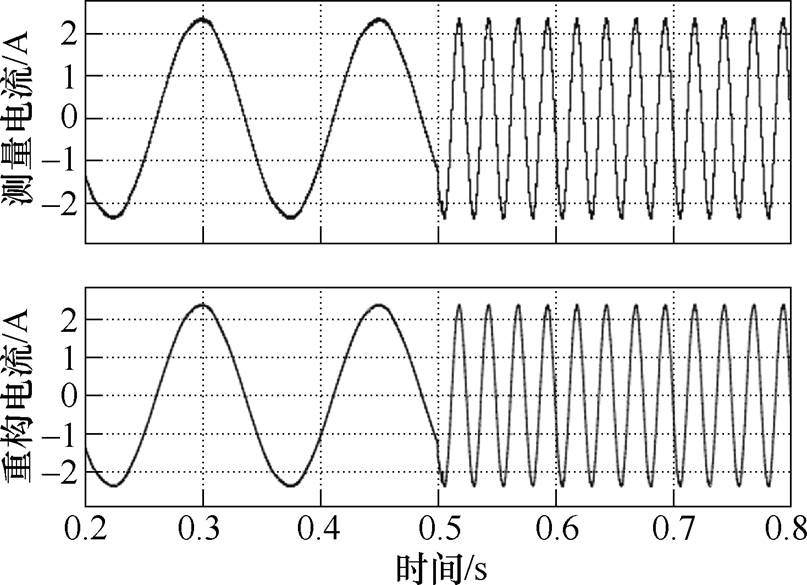
图15 转速调节时的电流重构仿真结果
Fig.15 Simulation results of current reconstruction during speed regulation
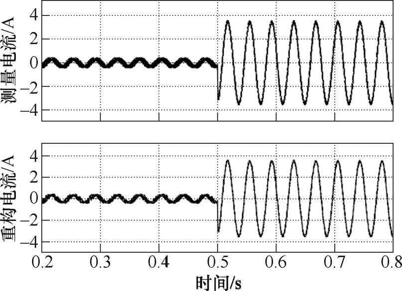
图16 负载突变时的电流重构仿真结果
Fig.16 Simulation results of current reconstruction during load step
2.1.2 电机驱动仿真结果
图17、图18分别为所提出的基于母线电流传感器的三相PMSM驱动系统转速调节、负载突变时的仿真结果。图17中,PMSM的负载设置为4 N·m,给定转速在200 r/min和600 r/min间来回切换。如图17所示,当给定转速由200 r/min提升至600 r/min时,驱动系统在10 ms内就可以完成转速的调节,电机实测转速能够迅速跟随给定转速,并且电机转速调节超调量小,证明该驱动方法的的动态调节性能好。此外,在系统稳态时,所提出的驱动方法的定子电流正弦性高,输出转矩稳定。图18中,PMSM的转速设置为400 r/min,负载转矩在0.5 N·m和6 N·m间来回切换。可以看出,在负载突变时,电机转速不发生较大波动,图18中,负载转矩突变时电机转速仅有1.25 %的波动,并且在20 ms内迅速恢复至给定转速。以上仿真结果证明了在系统暂态和稳态时,所提出的母线电流传感器驱动方法都具有较好的控制性能。
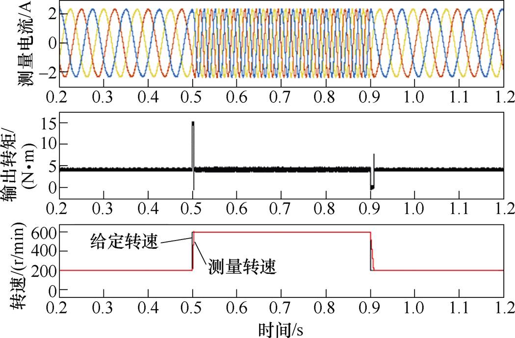
图17 驱动系统转速调节时的仿真结果
Fig.17 Simulation results under speed regulation of drive system
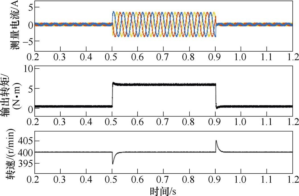
图18 驱动系统负载突变时的仿真结果
Fig.18 Simulation results under load step of drive system
为进一步验证所提出方法的有效性,搭建了实验平台并进行了实验验证。实验装置如图19所示,由两个三相PMSM、一个三相两电平的电压源逆变器、一个母线电流传感器、一个转速传感器和一个DSP28335控制板组成。其中,PMSM-1是实验测试电机,PMSM-2作为负载耦合连接至PMSM-1,逆变器开关管采用Infineon公司FF200R17KE3型号的IGBT,电流传感器型号为LEM公司LA25-NP型霍尔电流传感器,经测试得到最小采集时间Tmin=8 ms。实验测试参数与仿真一致。
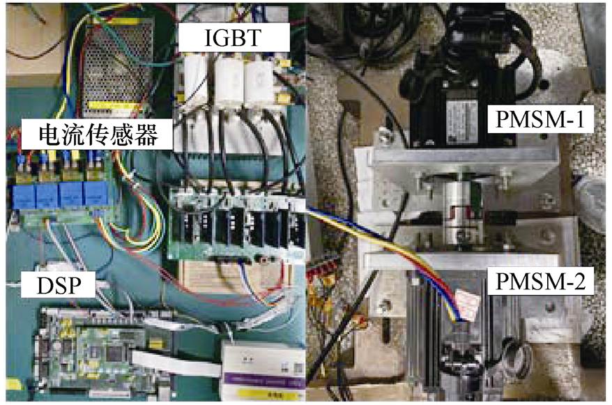
图19 实验装置
Fig.19 The experimental setup
2.2.1 电流重构实验结果
图20、图21分别为PMSM转速和负载发生变化时的a相电流重构结果。图20中的电机负载为4 N·m,电机转速由100 r/min增加至600 r/min。图21中的电机给定转速为400 r/min,设置负载从0.5 N·m增加至6 N·m。可以看出,重构电流与实测电流之间的误差小,并且波形中没有发现存在重构死区的迹象,证明了该电流重构方法在暂态和稳态时均具有较高的准确性。与图15、图16的仿真结果相比,图20、图21中实测电流与重构电流间的误差相对较大,这主要是因为实验过程中电流传感器存在测量噪声。
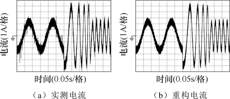
图20 转速调节时的电流重构结果
Fig.20 Current reconstruction results during speed regulation
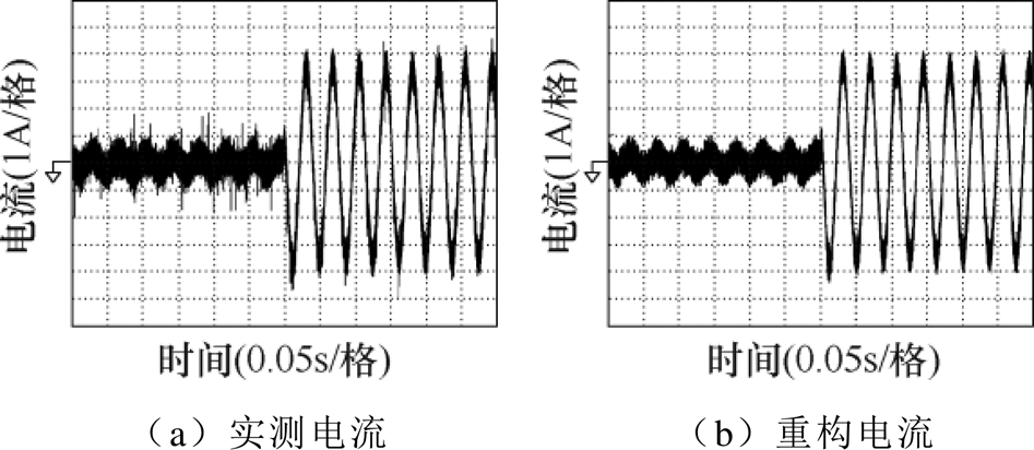
图21 负载突变时的电流重构结果
Fig.21 Current reconstruction results during load step
图22为PMSM低速轻载状态下的a相电流重构结果,电机转速为50 r/min,负载为0.5 N·m。图22a为不采用延长矢量法时的电流重构结果,可以看到,重构电流与实测电流间存在明显误差,这是TSPWM低电压区域的电流重构死区引起的。图22b为采用延长矢量法时的电流重构结果,可以看出,延长矢量法可以有效消除TSPWM低电压区域的电流重构死区引起的重构误差。
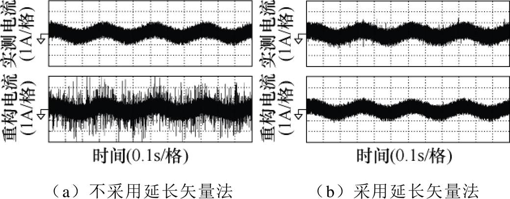
图22 低速轻载时的电流重构结果
Fig.22 Current reconstruction results with low speed and light load
2.2.2 CMV波形和开关状态平滑切换验证
图23a、图23b分别为传统SVPWM和所提出基于两步预测TSPWM的CMV波形。在一个控制周期内,传统SVPWM的CMV峰-峰值为直流母线电压值udc,而TSPWM的CMV峰-峰值仅为直流母线电压的1/3,因此TSPWM能够有效降低CMV对系统带来的危害。参考电压所在TSPWM扇区为1、3、5、2时,TSPWM输出的逆变器开关信号如图23c所示,图中点画线框圈画部分为零矢量插入部分,该零矢量(111)作用时间仅为4 ms,可以看出,选择合适的始末电压矢量有效避免了逆变器多相桥臂同时动作。
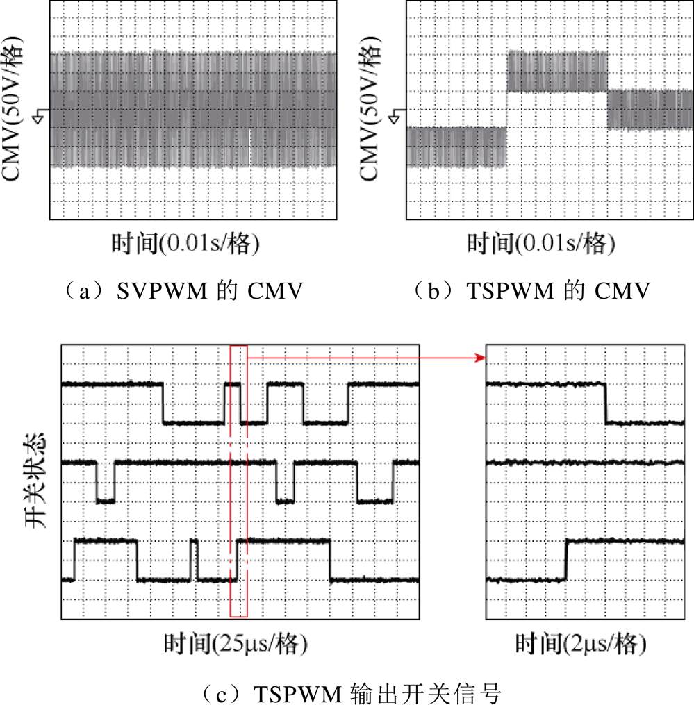
图23 TSPWM的共模电压波形与输出开关信号
Fig.23 CMV and switch signal of TSPWM
2.2.3 电机驱动实验结果
图24、图25分别为所提出的基于母线电流传感器的三相PMSM转速调节、负载突变时驱动系统的运行结果。图24中,PMSM的负载设置为4 N·m,给定转速在200 r/min和600 r/min之间来回切换。可以看出,提出的驱动方法的定子电流正弦性高、输出转矩稳定、动态调节性能好,电机实测转速能够迅速跟随给定转速。与图17所示的仿真结果相比,驱动系统在0.15 s内可以完成电机转速的调节,所需时间更长。此外,图24中电机稳态定子电流谐波含量更高、转矩波动也更大。这主要是由不准确的电机参数、逆变器电压损耗、传感器测量噪声等非理想因素导致的。
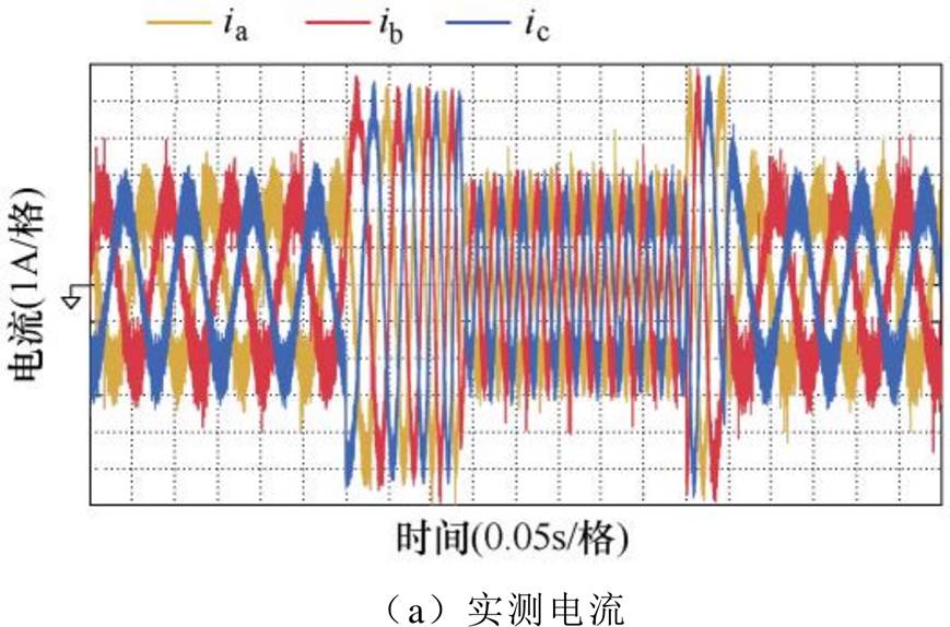
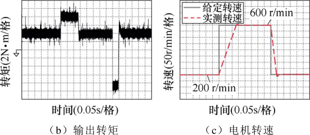
图24 转速调节时的驱动系统运行结果
Fig.24 Operating results of the drive system under speed regulation
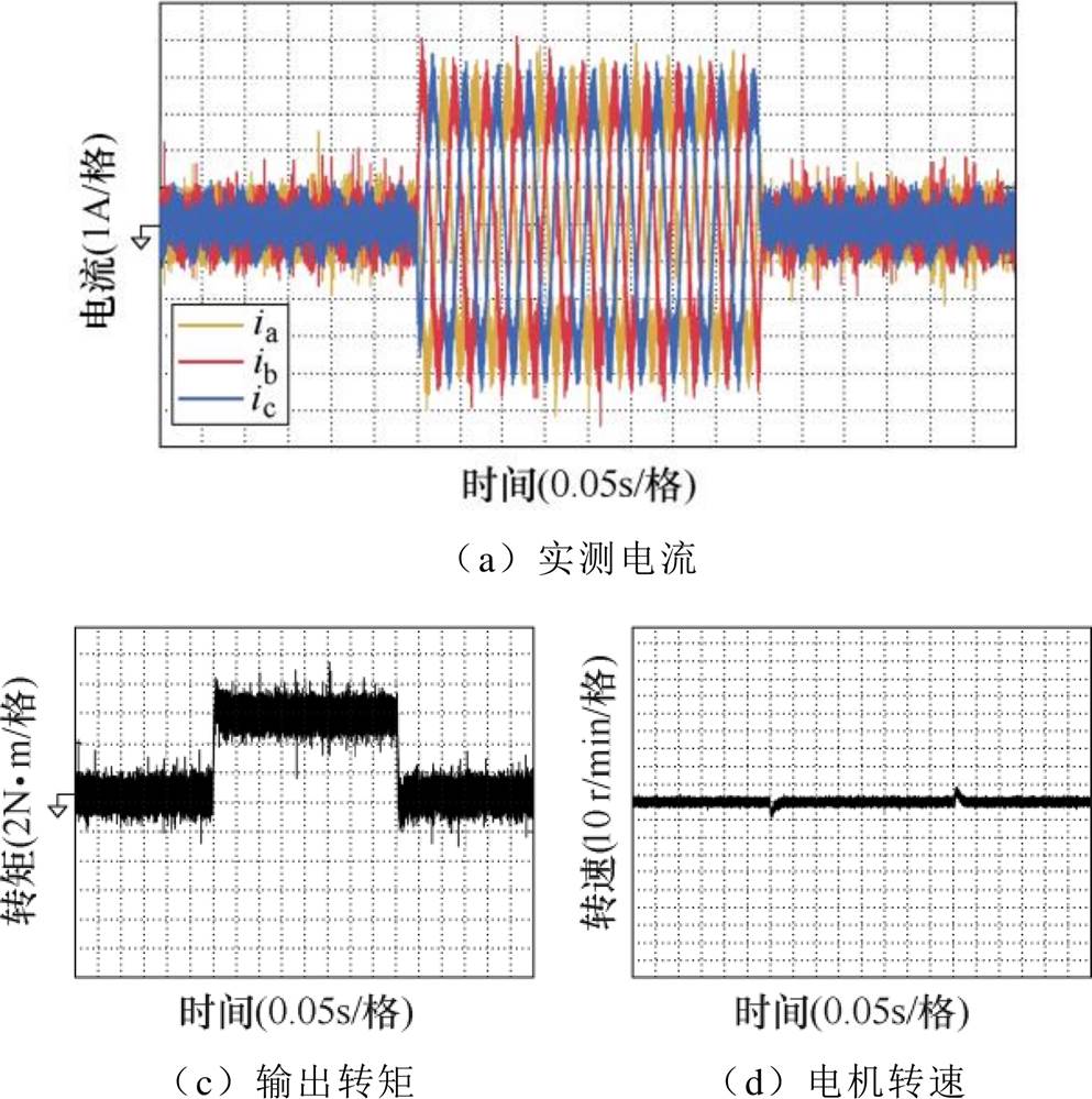
图25 负载突变时的驱动系统运行结果
Fig.25 Operating results of the drive system under load step
图25中,PMSM的转速设置为400 r/min,给定负载在0.5 N·m和6 N·m间来回切换。可以看出,在负载突变时,提出的驱动方法能够保持电机转速不发生较大波动。图25中负载转矩突变时电机转速发生约2.5 %的波动,稍大于仿真结果,随后电机转速在25 ms内迅速恢复至给定转速。
以上实验结果证明了在系统暂态和稳态时,所提出的母线电流传感器驱动方法都具有较好的控制性能。
2.2.4 驱动系统定子电流谐波分析
图26为所提出的单母线电流传感器驱动方法、传统的SVPWM矢量控制(Field-Oriented Control, FOC)和测量矢量插入(Measurement Vector Inserting, MVI)的SVPWM单母线电流传感器驱动方法[7]的定子电流总谐波畸变率(Total Harmonic Distortion, THD)比较。在PMSM给定转速为400 r/min的前提下,分别采用这三种驱动方法对不同负载下的电机进行控制,采集定子电流波形并对其进行快速傅里叶变换频谱分析以获取三种驱动方法的THD。插入测量矢量的单母线电流传感器驱动方法是目前应用最广泛的单母线电流传感器驱动方法,当参考电压位于重构死区时,MVI通过插入额外的测量电压矢量获取准确的相电流,实现定子电流的有效重构。从图26中可以看出,本文提出驱动方法的THD稍高于传统矢量控制驱动方法,这是因为比起七段式的SVPWM,五段式的TSPWM更容易产生高次谐波。此外,电机参数的不准确、逆变器的电压损耗等因素也会增加本文提出驱动方法的定子电流THD。随着负载的增加,本文提出方法和传统FOC间的THD差异逐渐变小。PMSM属于对THD容忍度较高的高电感负载,略微增大的THD对驱动系统造成的不良影响是可以接受的,并且相比于FOC,单母线电流传感器驱动拥有更高的可靠性。从图26可以看出,所提出驱动方法的THD明显低于MVI的THD,证明了所提出驱动方法的稳态控制性能明显优于传统的单母线电流传感器驱动方法。因此本文提出的单母线电流传感器驱动方法具有较高的应用价值。
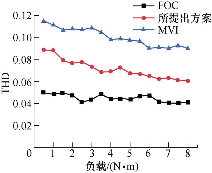
图26 定子电流THD比较
Fig.26 Comparison of stator current THD
本文研究了一种基于母线电流传感器的三相永磁同步电机驱动技术。使用TSPWM有效消除了电流重构死区的影响,使用两步预测控制获得当前周期与下一周期的参考电压并依此选择适当的TSPWM始末电压矢量,避免了逆变器多相桥臂同时动作。相比于其他单母线电流传感器驱动方法,所提出方法的电流采样点固定,不需要额外计算,并且具有较低的CMV峰-峰值。实验证明了该方法能有效使用母线电流传感器重构定子电流信号,并且在PMSM暂态和稳态都具有良好的驱动性能。最后将该方法和矢量控制以及传统单母线电流传感器驱动方法进行了THD对比,证明了该方法具有较好的驱动性能。
参考文献
[1] Zhang Jianzhong, Xu Zheng, Wang Jiayue, et al. Detection and discrimination of incipient stator faults for inverter-fed permanent magnet synchronous machines[J]. IEEE Transactions on Industrial Elec- tronics, 2021, 68(8): 7505-7515.
[2] 赵凯辉, 周瑞睿, 冷傲杰, 等. 一种永磁同步电机的有限集无模型容错预测控制算法[J]. 电工技术学报, 2021, 36(1): 27-38.
Zhao Kaihui, Zhou Ruirui, Leng Aojie, et al. Finite control set model-free fault-tolerant predictive control for permanent magnet synchronous motor[J]. Transa- ctions of China Electrotechnical Society, 2021, 36(1): 27-38.
[3] 陈文汉, 孙丹, 王铭泽. 断相故障下开绕组永磁同步电机模型预测控制容错控制策略研究[J]. 电工技术学报, 2021, 36(1): 77-86.
Chen Wenhan, Sun Dan, Wang Mingze. Research on fault-tolerance strategy based on model predictive control for open-winding PMSM system under open- phase fault[J]. Transactions of China Electrotechnical Society, 2021, 36(1): 77-86.
[4] 肖飞, 许观达, 连传强, 等. 永磁同步电机单电流传感器系统的三相电流重构策略[J]. 电工技术学报, 2022, 37(7): 1609-1617.
Xiao Fei, Xu Daguan, Lian Chuanqiang, et al. Three- phase current reconstruction strategy of permanent magnet synchronous machine drives using a single current sensor[J]. Transactions of China Electro- technical Society, 2022, 37(7): 1609-1617.
[5] 王伟, 程明, 张邦富, 等. 电流滞环型永磁同步电机驱动系统的相电流传感器容错控制[J]. 中国电机工程学报, 2012, 32(33): 59-66, 176.
Wang Wei, Cheng Ming, Zhang Bangfu, et al. Fault- tolerant control focusing on phase current sensors of permanent magnet synchronous machine drive systems based on hysteresis current control[J]. Proceedings of the CSEE, 2012, 32(33): 59-66, 176.
[6] Marčetić D P, Adžić E M. Improved three-phase current reconstruction for induction motor drives with DC-link shunt[J]. IEEE Transactions on Industrial Electronics, 2010, 57(7): 2454-2462.
[7] Hafez B, Abdel-Khalik A S, Massoud A M, et al. Single-sensor-based three-phase permanent-magnet synchronous motor drive system with luenberger observers for motor line current reconstruction[J]. IEEE Transactions on Industry Applications, 2014, 50(4): 2602-2613.
[8] Kim H, Jahns T M. Phase current reconstruction for AC motor drives using a DC-link single current sensor and measurement voltage vectors[C]//IEEE 36th Power Electronics Specialists Conference, Dresden, Germany, 2006: 1346-1352.
[9] Carpaneto M, Fazio P, Marchesoni M, et al. Dynamic performance evaluation of sensorless permanent- magnet synchronous motor drives with reduced current sensors[J]. IEEE Transactions on Industrial Electronics, 2012, 59(12): 4579-4589.
[10] 申永鹏, 郑竹风, 杨小亮, 等. 直流母线电流采样电压空间矢量脉冲宽度调制[J]. 电工技术学报, 2021, 36(8): 1617-1627.
Shen Yongpeng, Zheng Zhufeng, Yang Xiaoliang, et al. A compatible SVPWM method for DC bus current sampling[J]. Transactions of China Electrotechnical Society, 2021, 36(8): 1617-1627.
[11] 申永鹏, 王前程, 王延峰, 等. 误差自校正混合脉宽调制策略[J]. 电工技术学报, 2022, 37(14): 3643-3653.
Shen Yongpeng, Wang Qiancheng, Wang Yanfeng, et al. Error self-correction mixed pulse width modu- lation strategy[J]. Transactions of China Electro- technical Society, 2022, 37(14): 3643-3653.
[12] 黄政, 陈永军, 刘湃, 等. 基于单电流传感器的永磁同步电机高速控制技术[J]. 微电机, 2022, 55(1): 48-54.
Huang Zheng, Chen Yongjun, Liu Pai, et al. Per- manent magnetic synchronous motor high speed control technique based on single current sensor[J]. Micromotors, 2022, 55(1): 48-54.
[13] Im J H, Kim R Y. Improved saliency-based position sensorless control of interior permanent-magnet synchronous machines with single DC-link current sensor using current prediction method[J]. IEEE Transactions on Industrial Electronics, 2018, 65(7): 5335-5343.
[14] Yang S C. Saliency-based position estimation of permanent-magnet synchronous machines using square- wave voltage injection with a single current sensor[J]. IEEE Transactions on Industry Applications, 2015, 51(2): 1561-1571.
[15] Gu Yikun, Ni Fenglei, Yang Dapeng, et al. Switching- state phase shift method for three-phase-current reconstruction with a single DC-link current sensor[J]. IEEE Transactions on Industrial Electronics, 2011, 58(11): 5186-5194.
[16] 顾义坤, 倪风雷, 杨大鹏, 等. 基于母线电流传感器的相电流重构方法[J]. 电机与控制学报, 2009, 13(6): 811-816.
Gu Yikun, Ni Fenglei, Yang Dapeng, et al. Novel method for phase current reconstruction using a single DC-link current sensor[J]. Electric Machines and Control, 2009, 13(6): 811-816.
[17] Li Xiong, Dusmez S, Akin B, et al. A new SVPWM for the phase current reconstruction of three-phase three-level T-type converters[J]. IEEE Transactions on Power Electronics, 2016, 31(3): 2627-2637.
[18] Cho Y, LaBella T, Lai J S. A three-phase current reconstruction strategy with online current offset compensation using a single current sensor[J]. IEEE Transactions on Industrial Electronics, 2012, 59(7): 2924-2933.
[19] Xu Yongxiang, Yan Hao, Zou Jibin, et al. Zero voltage vector sampling method for PMSM three- phase current reconstruction using single current sensor[J]. IEEE Transactions on Power Electronics, 2017, 32(5): 3797-3807.
[20] Lai Y S, Lin Yongkai, Chen C W. New hybrid pulse- width modulation technique to reduce current dis- tortion and extend current reconstruction range for a three-phase inverter using only DC-link sensor[J]. IEEE Transactions on Power Electronics, 2013, 28(3): 1331-1337.
[21] Lu Haifeng, Cheng Xiaomeng, Qu Wenlong, et al. A three-phase current reconstruction technique using single DC current sensor based on TSPWM[J]. IEEE Transactions on Power Electronics, 2014, 29(3): 1542-1550.
[22] Cacciato M, Consoli A, Scarcella G, et al. Reduction of common mode currents in PWM inverter motor drives[C]//IEEE Industry Applications Conference Thirty-Second IAS Annual Meeting, New Orleans, LA, USA, 2002: 707-714.
Abstract In recent years,permanent magnet synchronous machine (PMSM) has been widely used in servo drive, rail transit, new energy power generation, and other fields for high power density, high efficiency, good reliability, and fast dynamic response. Three-phase PMSM drive systems usually require at least two phase current sensors to obtain accurate stator current signals. However, in harsh working conditions, the current sensor is prone to various faults or is affected by noise interference, resulting in inaccurate current signals collected. Inaccurate stator current feedback can cause the deterioration of the control performance. Therefore, this paper proposes a three-phase permanent magnet synchronous motor drive method based on a single DC-link current sensor, which reduces the number of current sensors in the drive system.
Firstly, the method uses a PI regulator to control the motor speed, and uses the bus current signal and the inverter switching state to reconstruct the stator current as current feedback. The principle of stator current reconstruction is the series effect of DC-link current and three-phase current. Secondly, the method uses the two-step model prediction algorithm to obtain the reference voltage of the next cycle instead of the current cycle. In the current cycle, the control system can simultaneously obtain the reference voltage of the current cycle and the next cycle through the two-step predictive control. Finally, tristate pulse width modulation (TSPWM) selects the appropriate starting and ending voltage vector to modulate the reference voltage of the current cycle according to these two sets of the reference voltage. When the TSPWM selects the appropriate starting and ending voltage vector, the area of the stator current reconstruction dead zone is greatly reduced, and the reconstruction dead zone is all located at the edge of the sector. Therefore, TSPWM can effectively eliminate the influence of the reconstruction dead zone, a tricky problem of traditional space vector pulse width modulation.
The simulation results show that the error between the reconstructed current and the measured current is small, which proves that the current reconstruction method has high accuracy in both transient and steady states. When the load of PMSM is set to 4 N m, and the given speed is switched back and forth between 200 r/min and 600 r/min, the drive system can complete the speed adjustment within 10 ms. The actual speed of the motor can quickly follow the given speed, and the overshoot is small. When the load is abruptly changed, the motor speed will not fluctuate greatly. The simulation results show that the motor speed fluctuates only 1.25 % when the load torque is abruptly changed, and it quickly returns to the given speed within 20 ms. In addition, in the steady state of the system, the stator current of the proposed driving method has a high sinusoidal, and the output torque is stable. These simulation results prove the performance of the driving method. Compared with the simulation results, the performance of the control system in the experiment decreases. It is mainly caused by non-ideal factors such as inaccurate motor parameters, inverter voltage losses, and sensor measurement noise.
The following conclusions can be drawn from the simulation and experiment. (1) Using TSPWM effectively eliminates the influence of the current reconfiguration dead zone. (2) Compared with other single-bus current sensor driving methods, the proposed method has fixed current sampling points and a lower CMV peak-to-peak value. (3) The method can effectively reconstruct the stator current signal using the DC-link current sensor and has good driving performance in both transient and steady states of PMSM. (4) The method performs better than vector control and traditional single DC-link current sensor driving method.
keywords:Permanent magnet synchronous motor (PMSM), DC-link current sensor, model predictive control, current reconstruction, tristate pulse width modulation
DOI: 10.19595/j.cnki.1000-6753.tces.220913
中图分类号:TM341
国家自然科学基金重点资助项目(51991384)。
收稿日期 2022-05-26
改稿日期 2022-07-12
郑晔明 男,1997年生,硕士研究生,研究方向为电机驱动及故障诊断。E-mail: jszym420@qq.com
张建忠 男,1970年生,研究员,博士生导师,主要研究方向为新能源发电和电力电子技术。E-mail: jiz@seu.edu.cn(通信作者)
(编辑 崔文静)