
Fig.1 The configuration of dual-stator motor
Abstract Dual-stator permanent magnet motors have attracted more and more attention in electric vehicles, renewable energy sources, and flywheel energy storage systems because of their advantages of compact structure, large power density, and high output torque. Nevertheless, the noise caused by the high-frequency electromagnetic force has become a serious bottleneck issue restricting the vibration-noise analysis of motors. Usually, finite element analysis (FEA) has been widely used in the multi-physical coupling analysisof electrical machinery. However, FEA faces some prominent disadvantages, including the strong dependence on mesh quality and high computational cost. In recent years, a meshless technique has received significant attentions. But it is worth noting that the shape function of meshless method can hardly fulfill the character of the Kronecker function. Hence, it is urgent to develop a quick and accurate coupling calculation technique that can combine advantages of two methods mentioned above.
Taking a dual-stator permanent magnet electric machine used in electric vehicles as an example, we proposed a multi-physical field coupling analysis technique combining FEA with an optimized meshless approach for accurate prediction of vibration-noise distribution. Firstly, a two-dimensional FEA electromagnetic model is established, then high-frequency electromagnetic forces exerted on the stators and permanent magnets under arbitrary currents are thoroughly studied. Secondly, forces are mapped into the three-dimensional structural model for harmonic response analysis employing FEA and the conventional meshless method, respectively. With the coupled multi-physics field analysis, precise boundary conditions and data transfer are keys to the precision of the proposed multi-physical modelling technology. In this research, it can be achieved by constructing a non-matching mesh data mapping matrix at the interface between FEA and meshless computational domains. Afterward, the vibration frequency response analysis results are treated as boundary conditions to calculate the radiated noise using FEA. Thirdly, the matrix of conventional meshless method suffers from the ill-conditioned defect in the process of convergence calculation. To mitigate this drawback, an optimized meshless method is proposed by modifying the local basis functions to recalculate the vibration-noise equation. Then the results of coupled simulation based on the traditional coupled FEA-meshless method, the optimized coupled FEA-meshless method, and the complete FEA coupled method are compared. Finally, the accuracy of the simulations is verified by a noise test, which indicated that the multi-physics field-coupled analytical approach was valid.
The following conclusions can be drawn from the simulation analysis: (1) Electromagnetic-vibration-noise evaluation considering high-frequency current harmonics are performed. It is found that frequencies of the vibration and noise in dual-stator rotor motors are quite different from those of conventional permanent magnet motors, namely the frequency of the magnetic force is same as the frequency of the current. Besides, forces from permanent magnets should also be fully considered. (2) To accomplish the data mapping, a non-matching mesh data mapping matrix at the interface between FEA and meshless computational domains are constructed to impose the boundary conditions, which can satisfy not only the continuity of function, but also the continuity of radial and tangential derivatives. (3) This paper proposes an optimized meshless approach based on the non-singular weighted function method. Compared with FEA and experiment, it has been confirmed that the optimized meshless method proposed can not only guarantee the calculation accuracy but also reduce the calculation time significantly.
Keywords:Dual-stator permanent magnet electric machine, finite element analysis, optimized meshless method, coupled analysis
Dual-stator permanent magnet motors have been attracting more and more attention in electric vehicles, renewable energy sources, and flywheel energy storage systems because of their advantages of compact structure, large power density, and high output torque[1]. Nevertheless, the noise caused by the high-frequency electromagnetic force has become a serious bottleneck issue restricting the vibration-noise analysis of motors[2]. Hence, developing a rapid and precise multi-physical coupling calculation method, which can not only effectively predict and evaluate the risk of research, but also contribute to the widespread application of electric vehicles.
Nowadays, traditional analysis of electrical machinery for new energy vehicles has covered analytical, semi-analytical, and pure numerical methods[3]. Among them, analytical method and semi-analytical approach have been successfully applied to the electromagnetic, vibration, and acoustic solutions[4]. However, for the dual-stator motor with its complex structure, a large number of equivalent magnetic circuits are needed to ensure the accuracy of the solution. Therefore, the excessive number of branches and nodes greatly increases the difficulty and workload of the solution, which makes the equivalent magnetic circuit method lose its unique advantages as a fast analytical modelling technique. Finite element analysis (FEA) is a mature and robust approach that has been successfully employed because of its adaptability and versatility characteristics to deal with boundary issues[5-9]. However, FEA is strictly restricted by the regionally variational concept and subdivision interpolation technique. Once the elements have been divided and the mesh has been formed, it is inconvenient to adjust parameters for solution accuracy. As a result, developing a quick and accurate coupling calculation technique for electrical machinery for new energy vehicles becomes more and more urgent.
Over the last several years, a meshless approach based on the scatter point approximation, which offers the benefits of fast calculation speed, high precision, and insensitivity to the distribution of discrete nodes, has gained much attention[10-11]. Therefore, this method has been widely employed in the addressing of issues relating to fluid dynamics, thermal optimization, and vibration problems[12-14]. However, this technology exhibits one prominent issue, namely the unknown quantity is typically the node parameters instead of the actual values[15]. As a consequence, the shape function hardly fulfills the character of the Kronecker function. Thus, it is difficult to apply the boundary conditions as conveniently and simply as FEA[16]. In order to overcome the drawbacks of meshless techniques mentioned above, combining the finite element approach with the meshless approach is considered to be the optimum scheme for an effective solution. Besides, there still exists a prominent limitation in dealing with acoustic problems based on the meshless approach, namely their being incapable of eliminating the pollution error effect in Helmholtz problems. Meanwhile, a relatively sophisticated operation for finding pollution terms is also a problem that cannot be ignored.
The main logic and structure of this manuscript can be defined as follows: Firstly, a two-dimensional electromagnetic FEA model is built, and the real-time three-phase currents are tested as the excitation sources for an expanded three-dimensional force solution. Secondly, taking the uneven distribution of nodal magnetic forces acting on the stators and permanent magnets as excitation sources, three-dimensional harmonic response analyses are carried out by FEA and conventional meshless approach respectively. For the coupled multi-physics field analysis combining FEA and meshless approach, particular attention should be paid to the data communication between the transient electromagnetic region computed by FEA and the vibration region computed through meshless approach. This can be performed by establishing a non-matching mesh data mapping matrix at the interface between the FEA and meshless computational domains. Afterward, using a similar data transmission method mentioned above, the vibration frequency response analysis results were applied as the boundary conditions to calculate the noise radiated based on FEA. Thirdly, an optimized meshless approach employing weighted orthogonal functions is proposed. Based on the previous coupling calculation, the harmonic response motion and noise radiation are recalculated to obtain the detailed natural frequencies and mode shapes. Finally, a noise test was carried out to validate the precision of the multi-physics field-coupled analytical approach. The result shows that the magnetic forces of stator teeth and permanent magnets are the two main sources that contribute most to the vibration. This research can clearly hold promise for the assessment and optimization of rotating machinery.
In this paper, the model of a permanent magnet motor with a dual-stator structure is demonstrated in Fig.1.The main electromagnetic and mechanical parameters of the motor are represented in Tab.1. The number of meshes in the electromagnetic solution is 954 784, while in the vibration and acoustic solutions it is 7 117 620 and 12 749 187, respectively. Therefore, the mesh generation will consume an abundance of solution time.
Fig.1 The configuration of dual-stator motor
Tab.1 Main parameters of motor

PartParameterValue External StatorOuter Diameter/mm40 Inner Diameter/mm35 Tooth Width/mm15 Yoke Thickness/mm3 Core Length/mm70 Inter StatorOuter Diameter/mm29.7 Inner Diameter/mm9 Tooth Width/mm10.05 Yoke Width/mm14 Yoke Thickness/mm14 Tooth Height/mm3.3 Core Length/mm70 RotorTooth Height/mmTooth Width/mm412.32 External Permanent MagnetHeight/mm2 Width/mm16.85 Magnetizationsradial Inter Permanent MagnetHeight/mm2.5 Width/mm3 Magnetizationsradial OthersRatedSpeed/(r/min)Air-Gap Length/mm600 0.6
In order to enhance the effectiveness of the solution and lower the simulation cost, the following hypotheses were adopted:
1) The tiny physical features inside the motor that exert an insignificant effect upon the strength of its structure, such as small holes, withdrawal grooves, and bolts, were neglected. Besides, the influence of the rotor and windings on the harmonic response analysis is not considered.
2) The stator core of the motor is composed of an anisotropic material, while the permanent magnet and the cabinet are regarded as isotropic materials. In addition, the stator teeth and permanent magnets can be regarded as the curved beam structure model, while the other parts are regarded as the shell structure model. The treatment of boundary conditions can be referred to the literature[17].
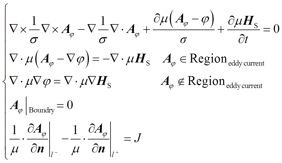
Solution domains of motor are divided into sub domains shown in Fig.1. The equation of magnetic field considering nonlinearity and anisotropy characteristics in a polar coordinate system is established[18]
 (1)
(1)
where, Aφ is the magnetic potential, φ is the electric potential; μ is the magnetic permeability;  is the magnetic field intensity; σ is the conductor conductivity;J is the current source density.
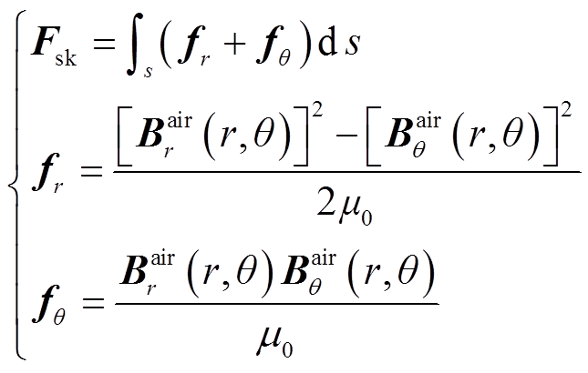
According to the Maxwell tensor approach, the electromagnetic forces acting on the surface of the internal and external stators and permanent magnets can be expressed as
 (2)
(2)
where, Fsk is the synthetic force;  and
and  denote radial and tangential electromagnetic forces acting on the surface s, respectively;
  and
and are radial and tangential magnetic induction intensity respectively.
While conducting an investigation into the analysis of the vibration and noise, the following hypotheses are made:
1) The minor physical structures on the motor that exert negligible influence on the structural strength, such as the groove and threaded hole near the slot opening, are neglected.
2) For vibration and noise analysis, the stator and cabinet are directly coupled through rigid nodes, and the influence of bolt pretightening force is ignored.
3)The boundary for the structural vibration analysis were as follows: For the modal calculation, a fixed constraint was added to the inner surface of the inner stator. For the harmonic response calculation, a similar process is performed. Besides, a fixed constraint was added to the contact face between the stator and the bolt.
The final discrete matrix equation based on FEA without considering the damping component can be shown as[19]
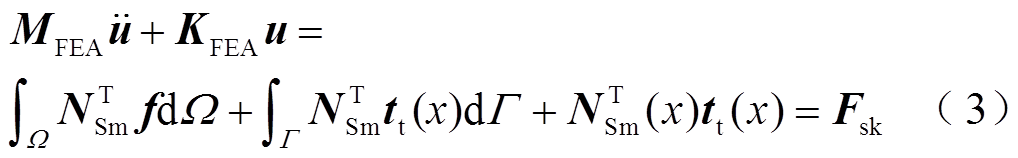
where, uis the vector of displacement; NSmis the shape function based on FEA; Ω and Γ are natural boundary and solution domain respectively; MFEA is the elementstiffness matrix shown in Equ. (4); KFEA is the elementstiffness matrix shown in Equ. (5); tt(x) denotes the concentrated force acting on the stress boundary.
 (4)
(4)
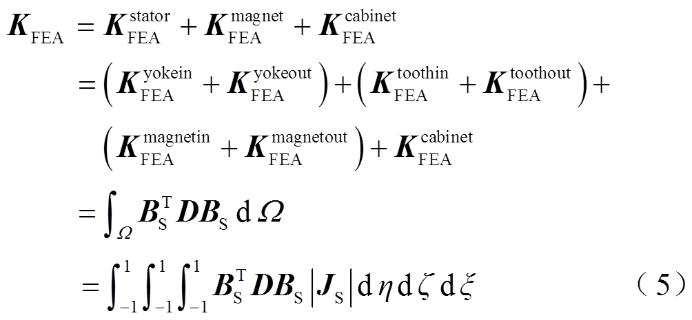
where,  is the density of material; JS is the Jacobian matrix; BS is the strain displacement transformation matrix based on FEA; D is the elastoplastic matrix;Kyokein FEAand Kyokeout FEAare stiffness operators stemming from internal and external stator yokes respectively; Kmagnetin FEAand Kmagnetout FEA are related to inter and external magnets respectively; Ktoothin FEAand Ktoothout FEA are concerned with stiffness operator regarding inter and external tooth; Kcabinet FEAlinks to the stiffness matrix from the cabinet of motor.
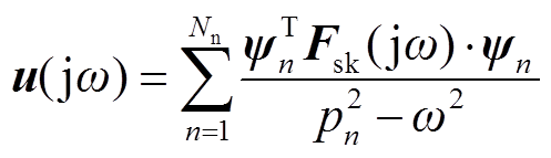
The vibration response can be expressed as a function of the mode and the excitation force:
 (6)
(6)
where, ![]() is the nth mass-normalized mode vector; ω and pnare respectively angular frequencies of the force and the nth mode.
is the nth mass-normalized mode vector; ω and pnare respectively angular frequencies of the force and the nth mode.
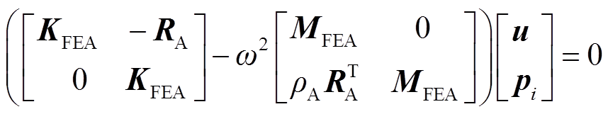
The final matrix form of the discrete equation for acoustic calculation excluding the damping matrix is expressed as
 (7)
(7)
where, ρA isthe density of air; ω is the angular velocity; RA is the coupling matrix of the structure field and sound field.
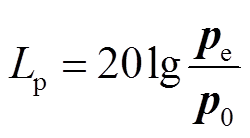
The sound pressure level can be calculated as
 (8)
(8)
where, Lp is the sound pressure level;  and
and  are measured sound pressure and reference sound pressure respectively.
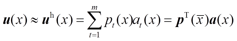
The nodal displacement function is estimated using the moving least squares (MLS) approximation over a set of discrete nodes, which can be described as[20]
 (9)
(9)
where, m is p(x) means the polynomial basis function vector in cylindrical coordinates for three-dimensional vibration issues;  is the node spatial coordinate inside the adjacent region. a(x) denotes the coefficient derived by minimizing the weighted discrete function, shown as
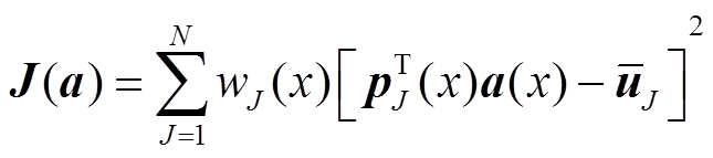 (10)
(10)
where,  is the displacement spatial coordinate inside the adjacent region. r=|x –
 /dms, dms=c×dx is the support radius, the parameter c denotes half number of points inside the adjacent support region, and dx means the distance between two nodes. For the stator yoke and cabinet regions, the weight function wJ(r) can be expressed as
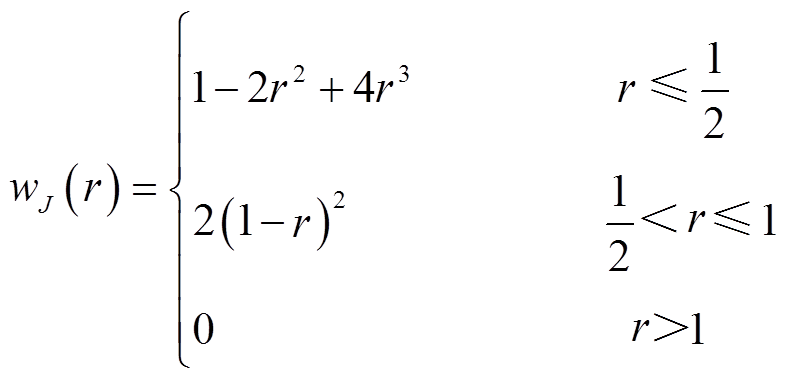 (11)
(11)
In view of stator teeth and surface-mounted permanent magnets regions, a smooth cosine weight function is introduced as
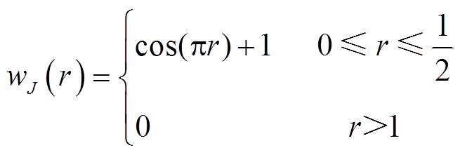 (12)
(12)
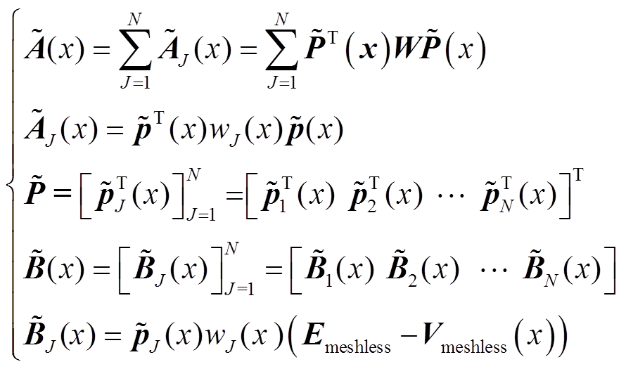
The newly formed shape function constituted by the conventional meshless approach is represented as
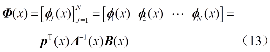
where, matrices A(x) and B(x) are defined as[21]
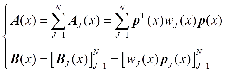 (14)
(14)
The final matrix form based on the conventional meshless method can be simplified as
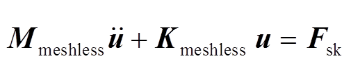 (15)
(15)
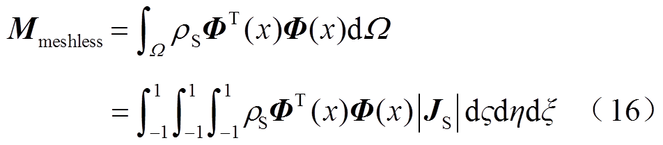
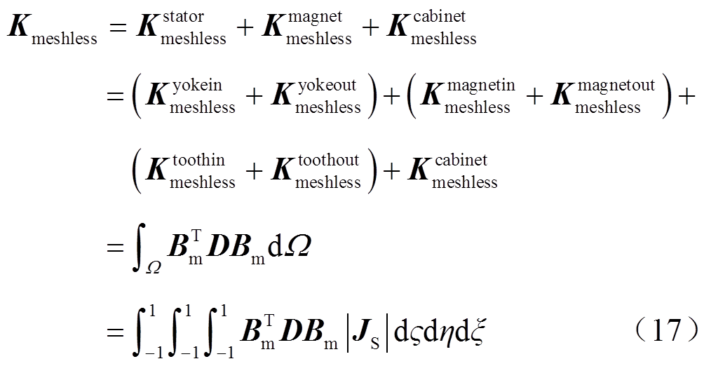
where, Bm is the strain displacement transformation matrix based on meshless method; Mmeshless denotes the mass matrix; Kmeshless denotes the stiffness matrix; other stiffness matrix expressions are similar to those in FEA.
For the coupling analysis between two-dimensional electromagnetic field calculation employing FEA and three-dimensional vibration and noise fields calculations employing the meshless approach, the data cannot be directly mapped. Furthermore, the approaches are generally based on the premise that excitation sources such as electromagnetic force and velocity are uniformly distributed[22]. To overcome those drawbacks, a data mapping matrix is proposed, associated with nodes between electromagnetic, vibration, and noise fields. Generally, the radial basis function (RBF) approach is employed to create the data mapping matrix. Unfortunately, the approximation function is not suitable for fitting the second order derivative, let alone satisfying consistency, leading to a large error. Moreover, it is essential to conduct fussy inverse operations during the process of establishing the shape function based on the RBF approach, which leads to the calculation matrix being easily ill-conditioned. Therefore, based on the moving least squares approach, the new mapping matrix is[23]
 (18)
(18)
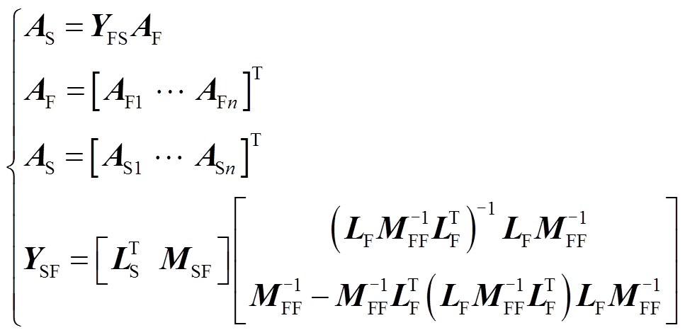
where, AS is the unknown node parameter in the structural calculation; AF denotes the known node parameters in electromagnetic calculations; YFS represents the mapping matrix; LFis a nF×4 matrix constructed by the parameters of electromagnetic field nodes; LSis a nS×4 matrix constructed by the parameters of structural field nodes; MFFis a nF×nF matrix constructed by the elements obtained by the basis function p(xFi-xFj); MSFis a nS×nF matrix constructed by elements obtained by the basis function p(xSi-xFj). The specific expressions of LF, LS, MFF and MSF are shown in Equ. (A1) and Equ. (A2) of Appendix.
The procedure for building the approximation function involves a significant number of calculations using the inverse of matrices. In order to speed up the convergence process, the standard method involves increasing the node density of the field while simultaneously decreasing the size of the support domain. Nevertheless, the accuracy of the calculation is very susceptible to the ill-conditioned matrix. Therefore, an optimized meshless method is proposed.
Similar to Equ.(9), the nodal function u is approximated over a series of discrete nodes with the non-singular MLS approximation as follows[24]
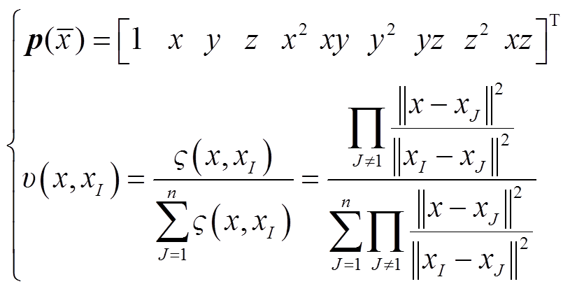
where,  (x) is the polynomials basis function based on the non-singular weight function and can be expressed as
 (20)
(20)
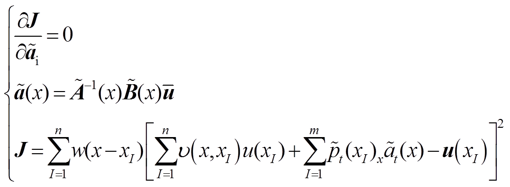
The coefficient  is determined by minimizing the weighted discrete norm, defined as[24]
 (21)
(21)
where, υ(x, is the operator function; matrices Aand B are
 (22)
(22)
Specially, Emeshless is a n×n unit matrix; Vmeshless is a n×n matrix constructed byυ(x, xI).
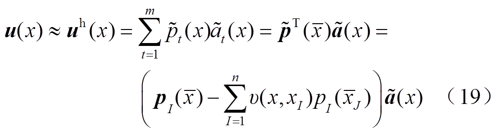
Finally, the approximation function is provided as
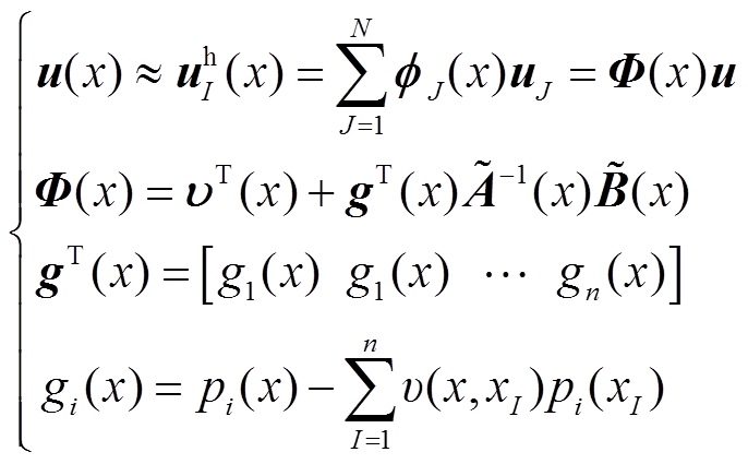 (23)
(23)
The primary excitation source of vibration is the transient electromagnetic force operating upon the permanent magnets and stator tooth tips. Hence, the first procedure of multi-physics coupling analysis is to acquire a precise determination of the force. In view of the electrical drive system, a frequency inverter with a space vector pulse width modulation (SVPWM) control strategy technique is generally employed. Consequently, the inverter operation generates a significant amount of current harmonics. Generally, these abundant harmonic components of currents are considered as the main excitation sources of electromagnetic noise. Therefore, it is essential to carry out an investigation on the frequency characteristics of the current.
Fig.2a shows the collected three-phase current curves, and Fig.2b shows the corresponding fast Fourier transform (FFT) analysis result of the current. It can be seen that collected currents contain abundant harmonics under the condition of an inverter power supply, and amplitudes achieve peak values at the frequency of 5 000 Hz. These harmonics will generate a high-speed rotating space harmonic magnetic field in the air gap, which will generate a large electromagnetic force wave in the motor and further increase the vibration and noise of the motor.
Collected three-phase currents are applied to the motor as excitations. The magnetic field and flux density distributions of the motor at 0.4 ms are shown in Fig.3. It is worth noting that the primary magnetic field inside the motor is not uniformly distributed, and the peak value is 1.80T. Besides, combined flux linkage generated by permanent magnets and armature reaction passes the inner and outer air-gap, closed loops occur at the inner and outer stator yoke respectively. Although saturation appears in some regions, flux generally follows the principle of minimum reluctance.
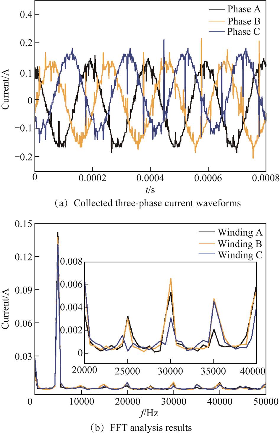
Fig.2 Tested three-phase currents and corresponding harmonic analysis

Fig.3 Transient electromagnetic field distribution of motor
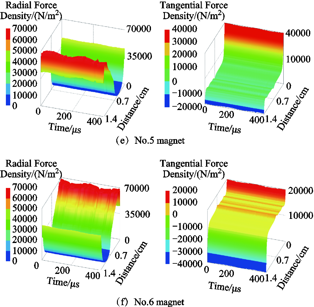
Taking the air-gaps of the inner and outer stator as observation paths, temporal-spatial distributions of electromagnetic force density are shown in App. Fig.1~App.Fig.4 of Appendix. It is worth mentioned that the distribution of electromagnetic force density is commonly compatible with the magnetic flux density, while the significant transformation occurs at the cogging joint. In addition, temporal-spatial distributions of radial electromagnetic force density exhibit great differences. For some regions, the tangential electromagnetic force density is even greater than the radial electromagnetic force density, which is also a potential source of vibration excitation and deserves special attention. Moreover, it is greatly worth noting that the spatial harmonic characteristics of the electromagnetic force wave generated by the interaction of the current harmonic and the fundamental wave of the air-gap magnetic field are basically independent of the harmonic frequency.
Frequencies analysis of Appendix acting on tooth tips were performed using the FFT analysis, illustrated in Fig.4. It is worth mentioning that the amplitudes and frequencies of electromagnetic forces in stator teeth and permanent magnets are significantly diverse due to the different excitation sources. Among them, for the permanent magnets, electromagnetic forces are mainly caused by the fundamental magnetic field, the peak values of amplitudes occur when f =0 Hz. For the stator teeth, due to the power supply of the inverter, the armature reaction magnetic field contains a large number of harmonics, which interact with the magnetic field of the permanent magnet to generate electromagnetic forces. However, due to the uneven distribution of the magnetic field, the amplitudes of the harmonic components of the internal and external stator teeth electromagnetic force are greatly different. Especially for the inner stator teeth, the tangent component of the electromagnetic force is much greater than the radial electromagnetic force. This again illustrates that the tangential electromagnetic force cannot be neglected.
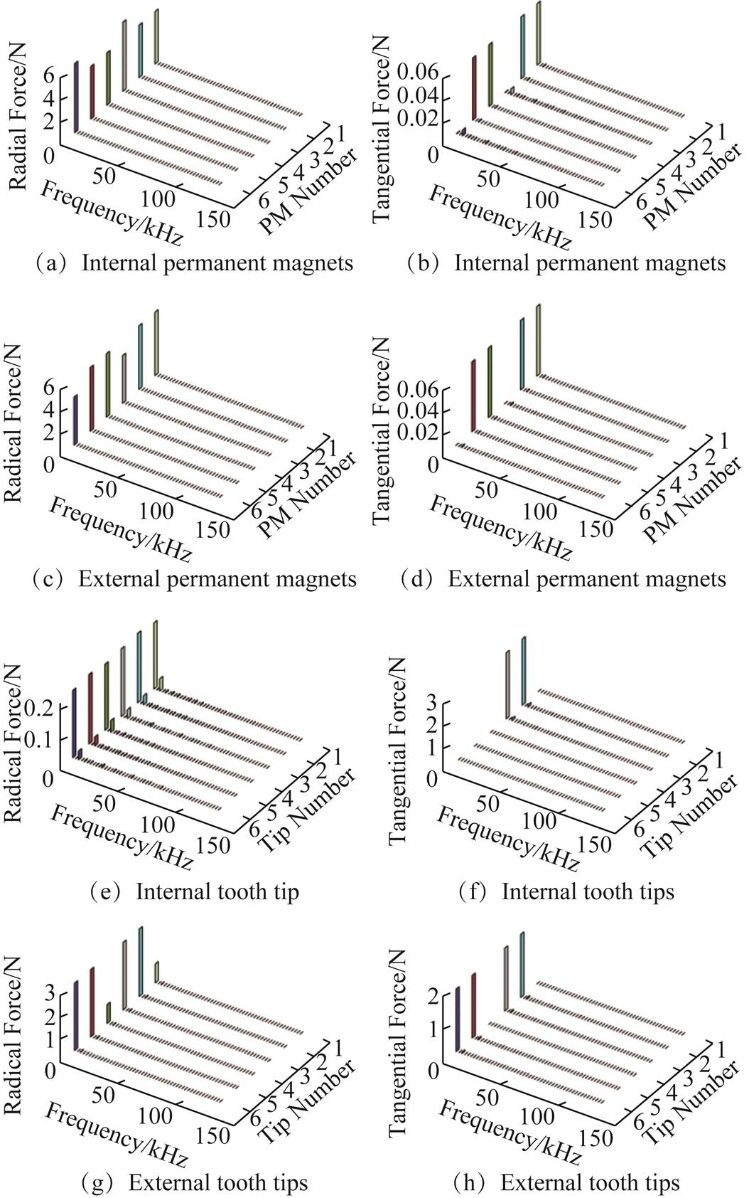
Fig.4 Harmonic analysis of electromagnetic magnetic forces
Fig.5 exhibits the three-dimensional node electromagnetic force of tooth-tips and permanent magnets mapping to the harmonic response calculation. As shown in Fig.5, distributions of electromagnetic force density are typically in accord with the magnetic flux density, while the large transformation occurs at the cogging junction. Besides, it can be found that the majority of electromagnetic force is concentrated upon the surface of stators and permanent magnets, which has a peak value of 7.05×10⁵ Pa. Compared with the external stator and permanent magnets, the internal stator and permanent magnets still have large electromagnetic forces, which are also the main excitation sources of vibration.
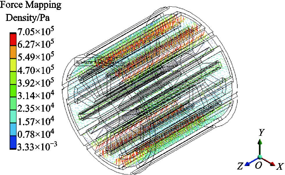
Fig.5 Electromagnetic force distribution inside the motor
Due to the fact that electromagnetic waves have multiple frequency components, when the frequencies of the force waves are close to the modal frequencies, it may cause a noticeable vibration. Therefore, it is necessary to carry on the modal calculation. The electromagnetic force wave directly acts on the stator teeth and rotor permanent magnet, which can cause the vibration and deformation of motor. It is worth noting that the amplitude of the stator yoke is much larger than those of the stator teeth and permanent magnets, thus following equations are applied to the modal analysis[25].
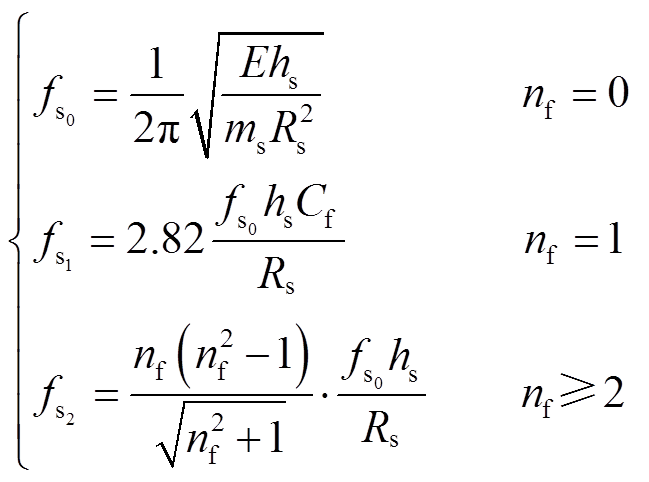 (24)
(24)
where, hs is the radial height of the yoke; ms is the mass of the stator; Rs is the radius of the stator yoke; nf is the order of force wave; Cf is the correction factor; E is 1.78×10¹¹ Pa.
The partial former 10th partial natural frequencies and corresponding mode shapes computed through FEA, analytic method, and the meshless approach are presented in Tab.2. It can be distinctly observed that the natural frequencies computed through the meshless methods are greater than those through FEA generally, while the relative errors of the 1st and 7th orders are relatively greater, namely 9.09% and 2.09% respectively. The reason is that the meshless approach considers the linear contact constraints between the stator yoke and the stator tooth in the modelling process, and the stiffness of the constraints is larger than the actual. Generally, the calculated errors of the optimized meshless method have been significantly reduced. In addition, the mode distributions of the motor are roughly the same, and the peak value of vibration appears at the outer surface of the external stator, while the vibration amplitudes at the front and rear ends of the cabinet are small. When the number of modal orders is lower, the deformation of stator teeth mainly demonstrates a tendency to bend radially.
Tab.2 Natural frequencies and mode shapes

Item1 st5 th AnalyticValuesFEAMeshlessOptimized MeshlessAnalyticValuesFEAMeshlessOptimized Meshless Mode Frequencies/Hz4984.614794.705437.74880.277002.236966.47497.96888.1 Relative Errors(%)3.819.092.090.517.081.63 Item7 th10 th AnalyticValuesFEAMeshlessOptimized MeshlessAnalyticValuesFEAMeshlessOptimized Meshless Mode Frequencies/Hz7263.156983.97719.67165.17403.377714.97997.97332.3 Relative Errors(%)3.846.281.354.208.030.96
For the purpose of verifying the solution results of the harmonic response analysis employing coupled FEA and double meshless approaches. Both the routine meshless approach and the optimized meshless approach are assumed to share the same structure model with complete FEA. Fig.6a and Fig.6b express displacement computed through FEA and routine meshless approach, respectively.
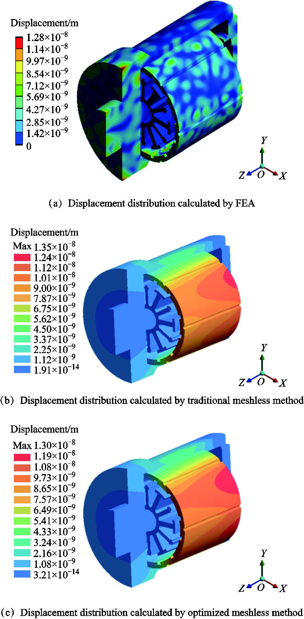
Fig.6 Displacement distribution of motor at 5 000 Hz
It can be seen that the maximum amplitudes of displacement are 1.28×10⁻⁸ m and 1.35×10⁻⁸ m, respectively, with an error of 5.47%. Accordingly, it can be noticed that the displacement calculated by the optimized meshless method shown in Fig.6c is 1.30×10⁻⁸ m and the error has been reduced to 1.56%. It is important to point out that there has been a significant improvement in the computation accuracy.
To fully exhibit the benefit of the meshless techniques proposed in the solution time, the computation times in the electromagnetic-vibration coupling process are presented in Tab.3 with the same computer. It is pointed out that the solution time of FEA is much longer than that of the meshless approach due to the generation of abundant meshes, particularly during the harmonic response analysis stage. The whole solution time for coupling calculation using complete FEA is approximately 18.7 times longer than that using the proposed approach combining the FEA with the conventional meshless approach. For the optimization meshless approach, the workload of the solution decreases due to getting rid of the tedious process of inversion operation on matrix A. As a result, it can save more calculation time.
Tab.3 Calculation times statistic

MethodFieldTime MeshCalculation FEAElectromagnetic15 min25 min Modal30 min50 min HarmonicResponse30 min10 h Total Times StatisticAbout 750 min MeshlessElectromagnetic—— Modal—3 s Harmonic Response—3.5 s Total Times StatisticAbout 6.5 s OptimizedMeshlessElectromagnetic—— Modal—2 s HarmonicResponse—2.5 s Total Times StatisticAbout 4.5 s
The experimental tests on the motor are carried out to further verify the proposed multi-physical field simulation model. The noise test is carried out in a semi-anechoic room, and the test bench is shown in Fig.7. The operation of the motor is driven by the SVPWM, and the carrier frequency is 50 kHz. The velocities on the cabinet surface calculated by FEA and meshless methods are transferred to the acoustic FEA model, respectively.
The acceleration of permanent magnet synchronous motor is shown in Fig.7b. At the electrical frequency of 5 000 Hz, the actual measured value of the motor is 0.34 m/s2, while the simulation value is 0.33 m/s2. The vibration trend of simulation and test are roughly equal, which can indicate that accuracy of the proposed method is adequate. Fig.7c shows the FFT results of the tested phase A current and vibration signal. It can be seen that the vibration frequency is the same as the current frequency due to the asymmetric magnetic pole structure.
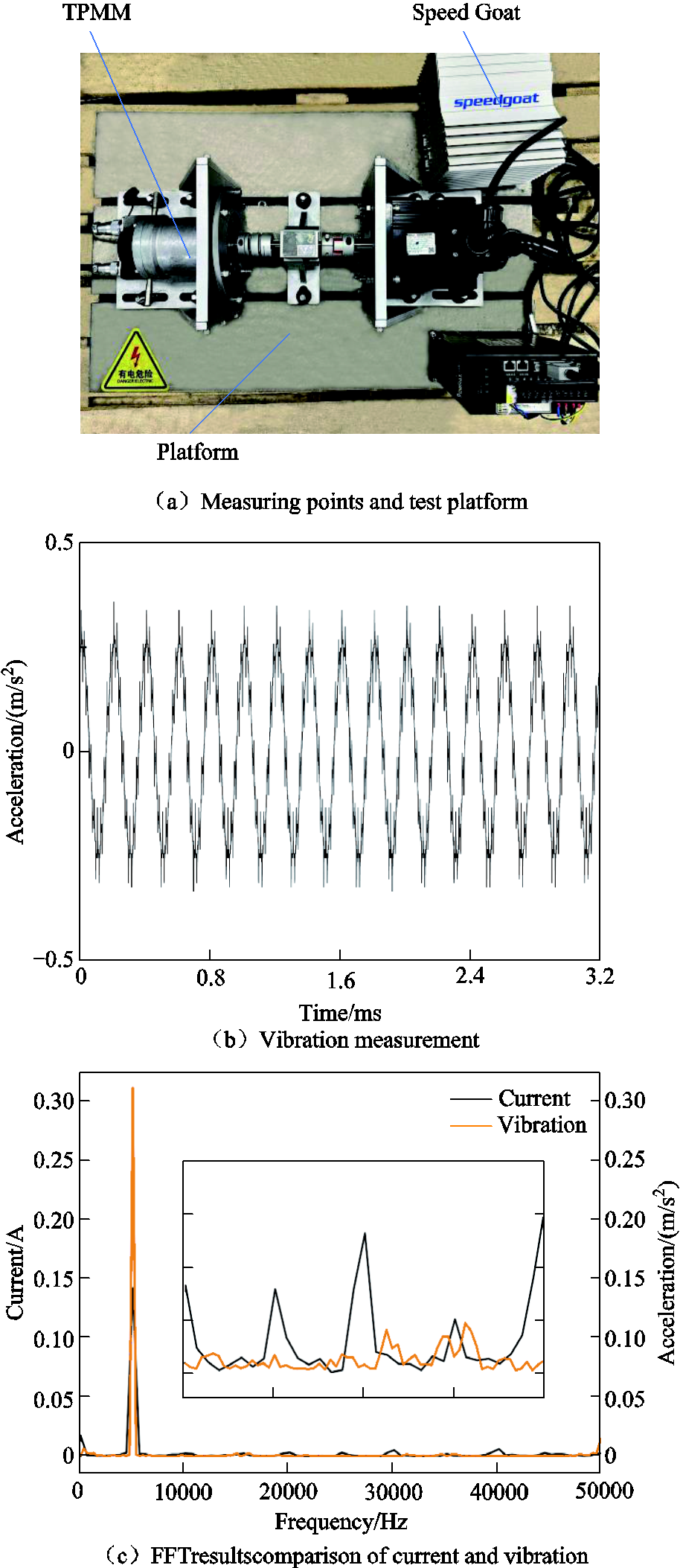
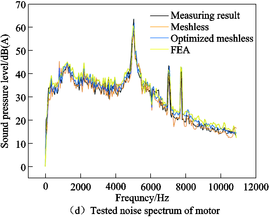
Fig.7 The test of motor
Fig.7d demonstrates the comparison of the noise spectrum between the measured results and the simulation results. It can be seen that the noise distribution exhibits obvious order characteristics. The peak values appear at 4 979.4 Hz, 5 026.2 Hz, and 7 012.8 Hz, respectively. Among them, 7 012.8 Hz is close to the 7th order natural frequencies of the motor respectively, while 4 979.4 Hz and 5 026.2 Hz are close to the 1st order natural frequency of the motor. When these force harmonics approach the modal frequencies of the motor, a typical phenomenon of resonance occurs. Obviously, the joint effect of the radial electromagnetic force of the internal stator and the natural frequency of the motor leads to an increase in the noise at these frequencies. Generally, results calculated by the optimized meshless method match well with the tested results over the full frequency range, while the error is large at the crest of the wave. The main reason is that the actual noise test inevitably includes the effects of electromagnetic noise, mechanical noise, and aerodynamic noise, while the simulation calculation only considers electromagnetic vibration. In addition, the contact of each component in the simulation model is treated as fully bonded, leading to the overall stiffness effect of the system larger. For the actual motor, the contact stiffness of each component should be reduced, and the damping will increase, which will seriously affect the harmonic response analysis. This is not obvious in the modal simulation, but it has a great influence on the amplitude simulation of vibration and noise.
Compared with the noise results at 5 000 Hz, the data of FEA, conventional meshless method, optimized meshless method and experimental test are 62.4 dB(A), 60.6 dB(A), 63.3 dB(A), and 65.9 dB(A), respectively. The main reason of the error is described as: for the FEA solution involving a large number of Gaussian integral operations, it is essential to make adjustments to both the compactly supported function and the distance factor to guarantee the continuity of interfacial integral equation between different regions. Besides, in order to avoid the intersection between the local sub-domain and the global boundary in the integral calculation, only the contributions of the Gaussian points located within the sub-domain are considered, while those outside the sub-domain are ignored.
In this research, a novel electromagnetic- vibration-noise calculation method by coupling FEA and optimized meshless method for dual-stator electric machine is proposed. The major conclusions are described as:
1) Electromagnetic-vibration-noise evaluation considering high-frequency current harmonics are performed. It is found that frequencies of the vibration and noise in the dual-stator rotor motors are quite different from those of conventional permanent magnet motors. Besides, forces exerted on permanent magnets should also be fully considered.
2) To accomplish the data mapping, a non-matching mesh data mapping matrix at the interface between FEA and meshless computational domains are constructed to impose the boundary conditions, which can satisfy not only the continuity of function, but also the continuity of radial and tangential derivatives.
3) This paper proposes an optimized meshless approach based on the non-singular weighted function method. Compared with FEA and experiment, it has been confirmed that the optimized meshless method proposed can not only guarantee the calculation accuracy but also reduce the calculation time significantly.
Appendix
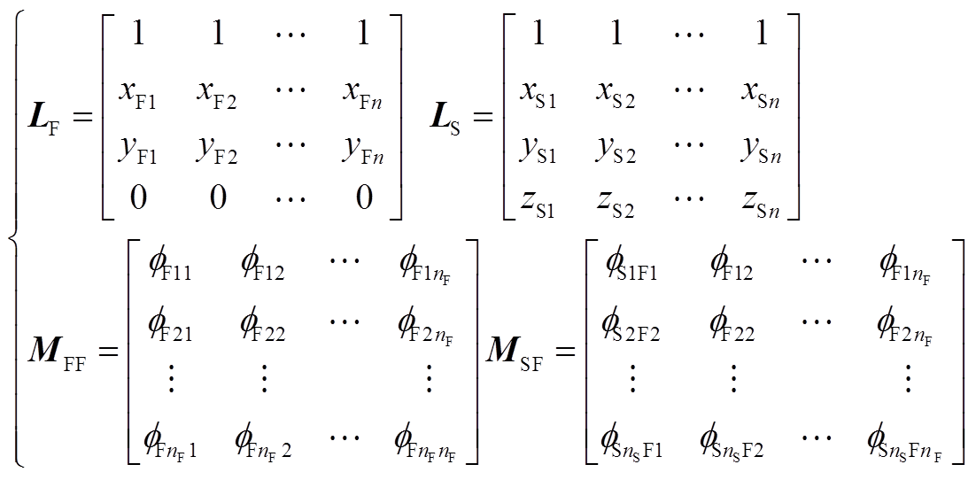 (A1)
(A1)
Analogously, for the harmonic response and noise coupling analysis of the three-dimensional model, the coefficients in Equ.(18) are:
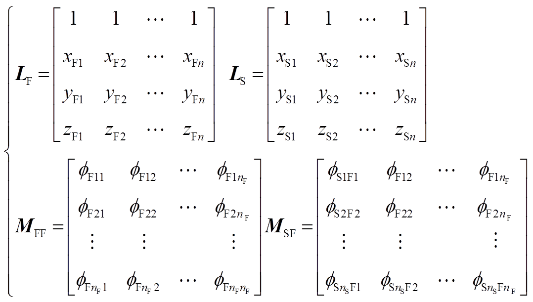 (A2)
(A2)

App.Fig.1 Temporal and spatial distributions of electromagnetic force density in external stator

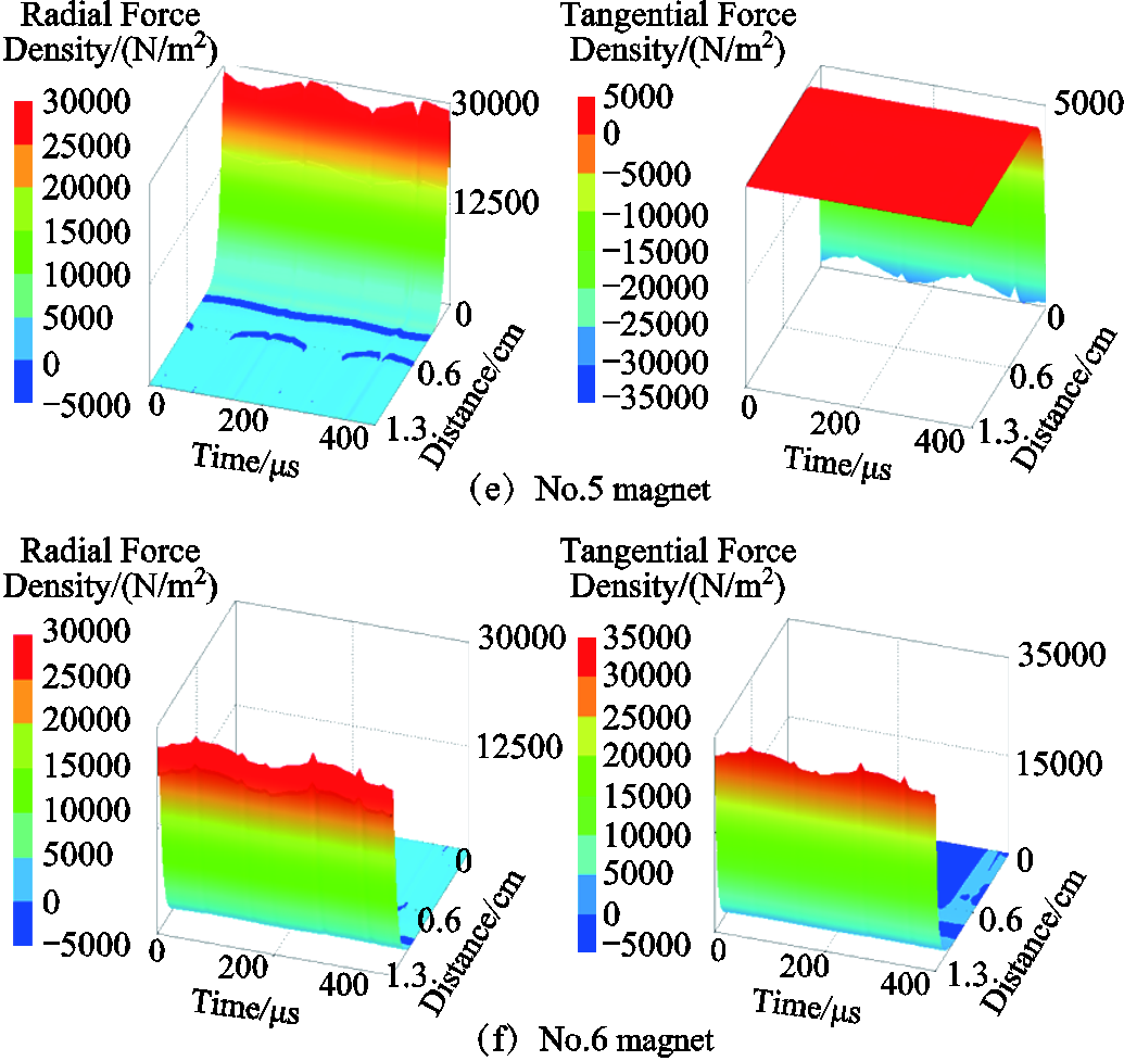
App.Fig.2 Temporal and spatial distributions of electromagnetic force density in internal stator

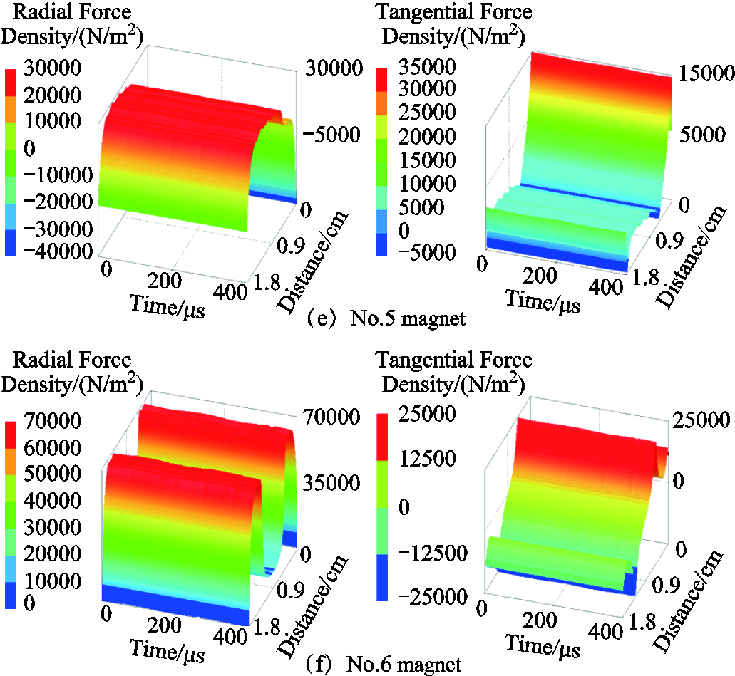
App.Fig.3 Temporal and spatial distributions of electromagnetic force density in external permanent magnets
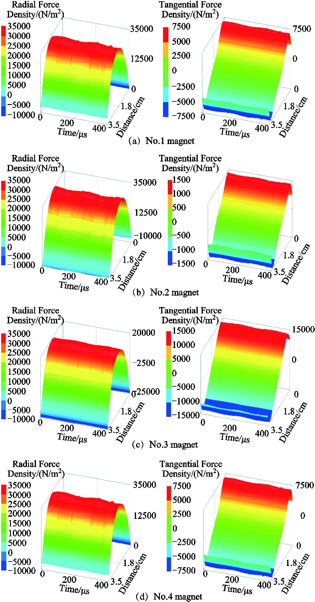
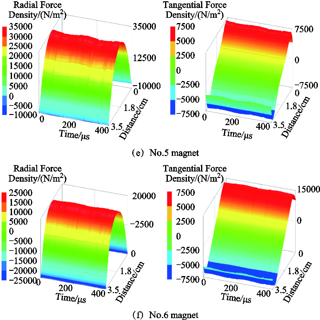
App.Fig.4 Temporal and spatial distributions of electromagnetic force density in internal permanent magnets
Reference
[1] Wang Jiyao, Qin Ling, Xu Wei. Design of adjustable cogging torque permanent magnet machine with high contrast ratio[J]. IEEE Transactions on Transportation Electrification, 2022, 8(3): 3478-3488.
[2] Zhu Z Q, Howe D. Electrical machines and drives for electric, hybrid, and fuel cell vehicles[J]. Proceedings of the IEEE, 2007, 95(4): 746-765.
[3] Lin Fu, Zuo Shuguang, Deng Wenzhe, et al. Noise prediction and sound quality analysis of variable-speed permanent magnet synchronous motor[J]. IEEE Transactions on Energy Conversion, 2017, 32(2): 698-706.
[4] Ye Caiyong, Yu Dezuan, Liu Kaifeng, et al. Research of a stator PM excitation solid rotor machine for flywheel energy storage system[J]. IEEE Transactions on Industrial Electronics, 2022, 69(12): 12140-12151.
[5] Yin Hang, Zhang Hengliang, Hua Wei, et al. Quantitative analysis of electromagnetic forces by decoupling air-gap field modulation and force modulation in rotor-permanent-magnet machines[J]. IEEE Transactions on Industrial Electronics, 2023, 70(2): 1310-1320.
[6] Yasa Y, Sozer Y, Garip M. Acoustic noise mitigation of switched reluctance machines with leaf springs[J]. IEEE Transactions on Industrial Electronics, 2023, 70(2): 1250-1260.
[7] Cao Junci, Deng Xiaoqing, Li Dong, et al. Electromagnetic analysis and optimization of high-speed maglev linear synchronous motor based on field-circuit coupling[J]. CES Transactions on Electrical Machines and Systems, 2022, 6(2): 118-123.
[8] Bao Xiaohua, Ming Shuai, Chen Guowei, et al. Analysis of radial electromagnetic force characteristics of inverter drive double skewed rotor induction motor[J]. Transactions of China Electro-technical Society, 2023, 38(10): 2613-2624.
[9] Hafeez M B, Krawczuk M, Nisar K S, et al. A finite element analysis of thermal energy inclination based on ternary hybrid nanoparticles influenced by induced magnetic field[J]. International Communications in Heat and Mass Transfer, 2022, 135: 106074.
[10] Li Size, Xu Wei. Vibration analysis of permanent magnet synchronous motor using coupled finite element analysis and optimized meshless method[J]. Nonlinear Dynamics, 2022, 108(1): 167-189.
[11] Bourantas G, Zwick B F, Joldes G R, et al. Simple and robust element-free Galerkin method with almost interpolating shape functions for finite deformation elasticity[J]. Applied Mathematical Modelling, 2021, 96: 284-303.
[12] Ye Zisheng, Hu Xiaozhe, Pan Wenxiao. A multigrid preconditioner for spatially adaptive high-order meshless method on fluid-solid interaction problems[J]. Computer Methods in Applied Mechanics and Engineering, 2022, 400: 115506.
[12] Cui Miao, Peng Haifeng, Xu Bingbing, et al. A new radial integration polygonal boundary element method for solving heat conduction problems[J]. International Journal of Heat and Mass Transfer, 2018, 123: 251-260.
[14] Qin Xia, Shen Yajing, Chen Wei, et al. Bending and free vibration analyses of circular stiffened plates using the FSDT mesh-free method[J]. International Journal of Mechanical Sciences, 2021, 202/203: 106498.
[15] Wang Lihua, Qian Zhihao. A meshfree stabilized collocation method (SCM) based on reproducing kernel approximation[J]. Computer Methods in Applied Mechanics and Engineering, 2020, 371: 113303.
[16] Zahur U, Baseer U, Wajid K, et al. Proportional topology optimisation with maximum entropy-based meshless method for minimum compliance and stress constrained problems[J]. Engineering With Computers, 2022, 38(6): 5541-5561.
[17] Qu Renhao, Jiang Weikang. An analytical method for vibration characteristics analysis of motor stator core[J]. Journal of Vibration and Shock, 2021, 40(3): 82-87.
[18] Wang Gepeng, Jin Wende, Zeng Xiangyang, et al. Analysis and control research on core vibration of UHV shunt reactor[J]. Transactions of China Electro-technical Society, 2022, 37(9): 2190-2198.
[19] Wu Q, Liu Fengbin, Cheng Yumin. The interpolating element-free Galerkin method for three-dimensional elastoplasticity problems[J]. Engineering Analysis With Boundary Elements, 2020, 115: 156-167.
[20] He Xingchuan, Yang J S, Mei G X, et al. Bending and free vibration analyses of ribbed plates with a hole based on the FSDT meshless method[J]. Engineering Structures, 2022, 272: 114914.
[21] Bourantas G C, Mountris K A, Loukopoulos V C, et al. Strong-form approach to elasticity: hybrid finite difference-meshless collocation method (FDMCM)[J]. Applied Mathematical Modelling, 2018, 57: 316-338.
[22] Zhu Ziyuan, Wang Gang, Xuan Zhihong, et al. Vibration analysis of the combined conical–cylindrical shells coupled with annular plates in thermal environment[J]. Thin-Walled Structures, 2023, 185: 110640.
[23] Liu Gang, Zhang Hanfang, Chi Cheng, et al. research on node data mapping algorithm for the 2D coupling electromagnetic-fluid-thermal fields[J]. Transactions of China Electrotechnical Society, 2018, 33(1): 148-157.
[24] Cheng Yumin. Meshless methods[M]. Beijing: Science Press, 2015.
[25] Shi Fangmin, Zhu Liwei. Research on modal vibration mode of permanent magnet synchronous motor stator system[J]. Electric Machines and Control System, 2018, 233: 77-81.
摘要 针对传统有限元法在电机的多物理场耦合计算过程中存在计算量大、耗时长、精度过于依赖网格剖分的缺点,而传统无网格法又存在边界条件施加不方便,在收敛计算过程中矩阵容易产生病态的缺陷。以一台电动汽车用双定子永磁电机为例,提出一种将有限元法与改进无网格法结合的多物理场耦合分析计算方法,来解决旋转机械的振动噪声计算问题。首先,建立电机二维有限元电磁模型,然后深入研究了考虑任意电流激励下的电机电磁力。其次,分别将内外定子齿及永磁体电磁力导入基于有限元和无网格法的三维结构场中进行谐响应分析。在多物理场耦合分析过程中,精确的边界条件和数据传输是求解的关键所在。该文通过在有限元法与无网格法交界面之间的过渡区域内构造一个不匹配的网格数据映射矩阵,可以较好地解决有限元-无网格耦合计算边值问题,实现了两种方法之间的数据映射。然后,将振动分析结果作为边界条件,利用有限元法计算辐射噪声。再次,针对传统无网格-有限元耦合方法求解过程中存在截断误差的缺点,提出构造一种通过修改局部基函数的方法对无网格法进行优化并重新计算谐响应运动。最后,将这两种无网格方法仿真结果与基于有限元计算结果及实验进行对比,在验证了该文耦合计算结果的准确性的同时,还发现改进后的无网格耦合计算方法不仅在精度和鲁棒性上有所提高,而且求解速度远高于传统有限元法耦合求解。该计算方法可以为旋转机械的多物理场耦合计算提供新的思路。
关键词:双定子永磁电机 有限元分析 优化无网格法 耦合分析
中图分类号:TU313; TM351
DOI:10.19595/j.cnki.1000-6753.tces.230998
This work is supported by the National Natural Science Foundation of China (52275009, 52037002, 52207038), the National Double First-class Construction Special Funds (4316002181) and the Fundamental Research Funds for the Central Universities (3216002101A2, 3216002209A1).
Received 2023-06-28;
Revised 2023-07-31
Note Brief
Li Size Male, born in 1990, PhD Candidate, Major research interests include coupled multi-physics field analysis of motor and electric apparatus. E-mail: lisize@seu.edu.cn
Xu Wei Male, born in 1982, IEEE Member, PhD. Major research interests include design, control, and applications of permanent magnet machines and drives for applications ranging from automotive to renewable energy.E-mail: weixu@seu.edu.cn (Corresponding author)
(编辑 郭丽军)