 (1)
(1)
摘要 无速度传感器感应电机系统在低速、变负载工况运行时,转速可观测性较差。为此,提出一种负载变化下无传感器感应电机主动零频穿越及脉动抑制策略。首先,基于误差系数矩阵行列式分析,阐述了低速发电不稳定的原因,揭示了负载变化对感应电机低速运行稳定性的影响,指出负载变化下恒励磁电流策略存在转速不可观测、系统稳定性差等问题。进而,以提高负载变化下系统的转速可观测性为目标,引入主动零频穿越策略,并基于定子电流限制推导出励磁电流自适应变化区间与其修正步长。为提升系统稳态带载能力,分析了同步转速限制值对电机转矩输出能力的影响,并给出同步转速限制值取值范围。此外,为抑制主动零频穿越过程中的转速/磁链/电流脉动,保证电磁转矩和负载实时匹配,提出转矩电流相位补偿方法。最后,在2.2 kW的感应电机实验平台上验证了所提方法的有效性。
关键词:感应电机 无速度传感器控制 零频穿越 脉动抑制
无速度传感器感应电机系统以其结构简单、体积小、成本低、易于维护等优点,被广泛应用于工业生产中[1-2]。在电力传动、海上钻探等领域,感应电机时常工作在定子电流近零频工况。模型参考自适应系统[3]、全阶磁链观测器[4]、滑模观测器[5]等传统控制方案,无法保证无速度传感器感应电机系统在低速发电工况运行时的稳定性,严重制约了该系统的推广和大规模应用。
为提高无速度传感器感应电机系统在低频工况下的运行性能,研究人员进行了大量的探索。文献[6]从传统自适应转速观测器开环零、极点分布及根轨迹簇变化切入,详细介绍了无速度传感器感应电机以极低速发电工况运行时的不稳定问题。文献[7]基于转速观测与磁链观测的充要条件推导了无速度传感器感应电机系统的不稳定转矩边界。文献[8]中提出一种基于改进指数趋近律的滑模观测器,通过削弱传统滑模观测器中的系统抖振,提高了系统转速观测收敛速度。文献[9]引入了电流误差的d轴分量修正转速自适应律,通过劳斯判据获得d轴分量取值范围,在一定程度上增强了全阶观测器的稳定性。以提高转速观测稳定性为目标,除修正转速自适应律外,还可通过增加反馈矩阵设计自由度来增强观测器的局部稳定性[10]。文献[11]针对低速发电工况下系统运行性能差的问题,提出一种基于最小励磁电流误差原则的反馈矩阵设计方法,改善了电机在低速发电区域的运行性能。文献[12]在线计算感应电机磁链误差项,将其引入全阶观测器的反馈矩阵设计,可实现对感应电机动态过程的跟踪并稳定穿越低速发电不稳定区。文献[13]构建了“全局”稳定的自适应观测器,实现了除零频外的低速发电区域稳定运行。实际上,所有基于模型法的无速度传感器感应电机系统在定子电流零频线上均会失去转速观测能力,因此在定子电流零频工况下,无速度传感器感应电机转速是不可观测的[14]。
上述文献在一定程度上可以提高无速度传感器感应电机系统在低速发电区域运行的稳定性,但在定子电流零频线附近仍然没有实现稳定的转速观测。为解决该问题,文献[15]区分零转子转速运行工况与零定子电流频率运行工况,采用虚拟电压注入法构造转速观测误差,提高了低定子频率运行的稳定性,但无法避免转速观测误差和转矩脉动。文献[16]提出了一种基于感应电机虚拟电压注入法的在线切换系统,兼顾了低转速发电区域系统稳定性与高转速区域系统观测精度需求,但该文中转子磁链实时计算方法对电机参数和运行工况变化敏感,在临界状态会引入严重的噪声和振荡。文献[17]为增强转速可观测性,提出了一种基于励磁电流自适应控制的低频穿越方法。该方法可以解决恒定负载下因转速过低导致的转速不可观测问题。但是,当感应电机处于发电工况时,负载变化亦可导致系统因定子电流频率过低而失稳。该文献没有考虑发电负载变化下的零频穿越问题。
针对上述问题,本文提出一种负载变化下无传感器感应电机主动零频穿越及脉动抑制策略,基于定子电流限制设计发电负载变化下的主动零穿过程,自适应修正励磁电流,维持电机的同步转速在预设的限制值之外,实现了定子电流近零频工况下转速可观测,并给出可提升系统稳态带载能力的同步转速限制值取值范围。进一步地,励磁电流自适应修正时,以电机转矩与负载实时匹配为目标,对转矩电流进行相位补偿,实现了主动零频穿越过程中对转速/磁链/电流脉动的抑制。
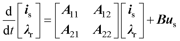
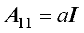
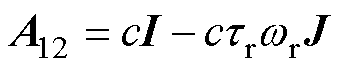
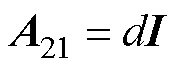
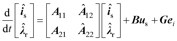
参考两相静止ab 坐标系下感应电机T型等效电路,选取定子电流与转子磁链作为状态变量,感应电机数学模型可以表示为
(1)
其中
式中, 、
、 、
、 分别为定子电流矢量、转子磁链矢量和定子电压矢量;Rs、Rr分别为定、转子电阻;Ls、Lr、Lm分别为定子电感、转子电感及互感;wr为感应电机转子转速。
根据式(1)中的感应电机数学模型,两相静止坐标系下感应电机自适应全阶观测器模型可表示为
 (2)
(2)
其中
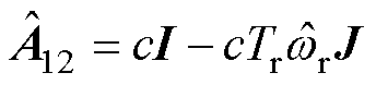
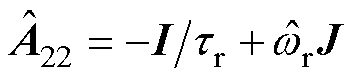
式中,G为观测器的反馈矩阵, 为估计转速。
式(1)减去式(2),可得定子电流和转子磁链的误差矢量表达式为
 (3)
(3)
其中

基于式(3),应用波波夫超稳定性定理,可得式(2)中转速自适应律的表达式[18]为
 (4)
(4)
引入转子转速误差扩展误差矢量表达式,令
 (5)
(5)
针对某一确定的电机运行工况点进行小信号线性化,可得无速度传感器感应电机系统的扩展误差矢量表达式[19]为
 (6)
(6)
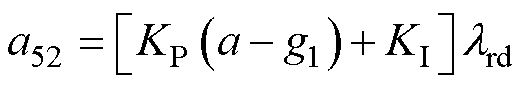
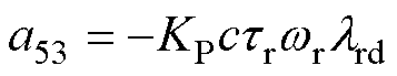
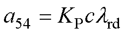
式(6)中的误差系数矩阵为
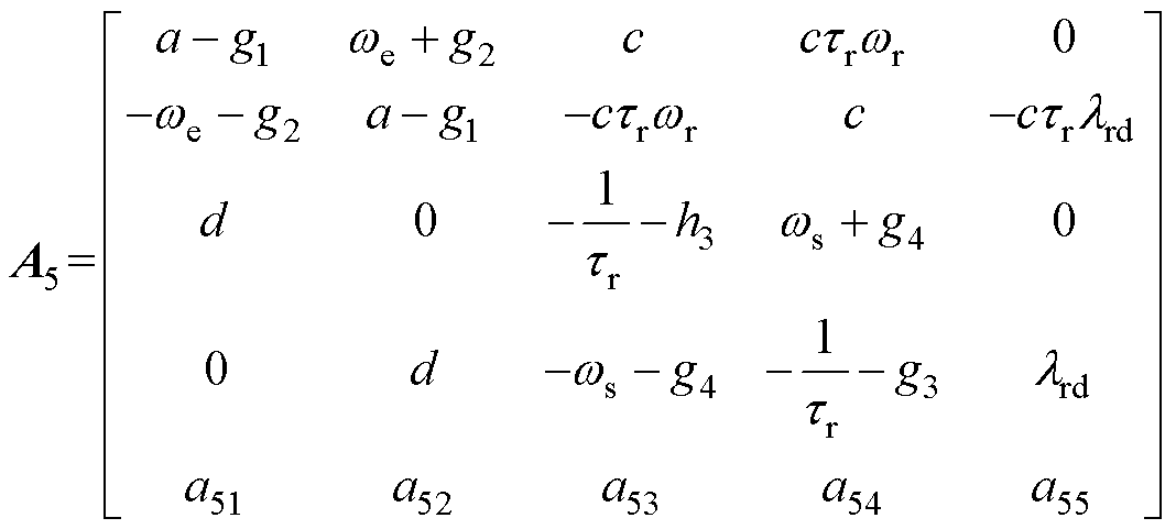 (7)
(7)
其中

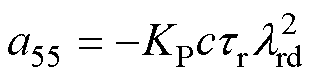
令矩阵A5的行列式为零并采用零反馈矩阵,可得无速度传感器感应电机系统在低速发电区域运行时的不稳定边界为
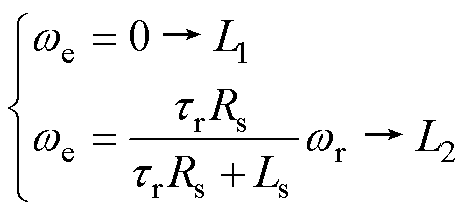 (8)
(8)
结合感应电机的同步转速计算式we=ws+wr,将式(8)所示的不稳定区域边界线绘制在wr-ws坐标系中,即可得到如图1所示的低速发电不稳定区域。通常,合理选择反馈矩阵参数可以有效削减不稳定区域。但由于温升或磁场饱和等因素,控制器中预设的电机参数与感应电机实际参数之间的误差不可避免。即使采用一定的反馈矩阵设计,也无法完全消除不稳定区域[20]。因此,在恒转速变转矩的负载变化工况下,定子电流处于低频乃至零频时转速不可观测问题亟待解决。
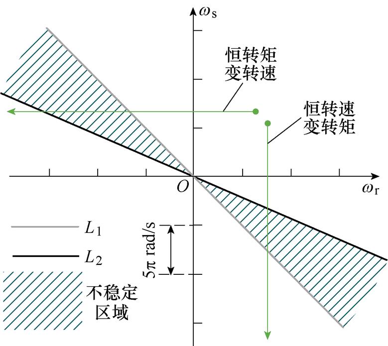
图1 低速发电不稳定区域
Fig.1 The low-speed unstable regenerating region
在两相同步旋转坐标系下,感应电机的同步转速we、转差转速ws、转子转速wr满足
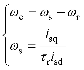 (9)
(9)
由于转速环的作用,感应电机的电磁转矩随负载变化而变化,以保持转速恒定。此过程中,感应电机的电磁转矩表达式为
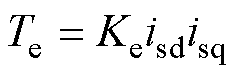 (10)
(10)
式中, 为转矩表达式系数,
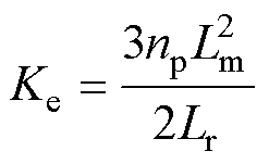 。
。
传统方法中,感应电机的励磁电流被设置为恒定值。当负载变化时,根据式(10),转矩电流也随之变化。感应电机运行于发电工况时,结合式(9)与式(10)可知,此时电机的转差转速也为负。当发电负载不断增大时,电机的转差转速绝对值也不断增大时,电机运行工况点将进入不稳定区域。若不采取措施,电机将因为同步转速过低而失稳。
主动零频穿越策略旨在提高发电负载变化下的转速可观测性,保证无速度传感器矢量控制系统始终稳定,并解决2.1节中所述带载能力变差问题。
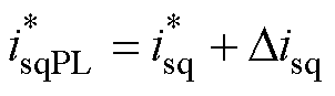
当发电负载达到一定值,使得感应电机的同步转速达到主动零频穿越策略设置的限制值wlim时,自适应修正感应电机的励磁电流指令值,即
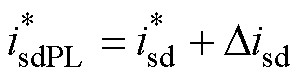 (11)
(11)
式中, 为修正后励磁电流指令值;
 为初始励磁电流指令值;
 为励磁电流指令值修正步长。
式(11)通过自适应修正励磁电流指令值,控制感应电机励磁电流自适应变化,更改电机转差转速,将同步转速维持在预设的限制值wlim。
当发电负载不断增大时,主动零频穿越策略作用下,感应电机运行工况点变化如图2a所示。P0点表示感应电机处于电动工况;当电动负载转为发电负载,且负载绝对值不断增大时,电机运行工况点达到同步转速限制值,即图2a中P1点,此时主动零频穿越策略使能,励磁电流自适应增加,电机工况点上移,达到P2点,电机同步转速同时远离限制值;发电负载继续增大,电机运行工况点从P2点下移至P3点,主动零频穿越策略将再次使能。如此循环往复,感应电机的运行工况点始终保持在不稳定区域之外。当励磁电流增加到某个特定区间,为保证全过程的转速可观测,需快速减小励磁电流,使感应电机快速穿越定子电流零频区域,保证低频运行乃至零频穿越过程中系统的稳定性,如图2a中P7点至P8点所示。零频穿越过程中电流矢量的变化如图2b所示。

图2 发电负载变化下的主动零频穿越策略
Fig.2 Proactive low-frequency ride-through method under variable regenerating load condition
对于实际的感应电机,其励磁电流并不能无限制地增大或减小。在某一确定的负载下,其零频穿越的边界点有上下确界。在定子电流坐标平面的电流限制圆内,励磁电流下限点设为点A,上限点设为点B。则点A与点B的坐标分别为
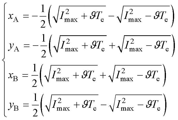 (12)
(12)
式中, 。
。
考虑到本文所提出的主动零频穿越策略应适用于负载变化的所有情况,将发电工况下负载绝对值减小时电机运行工况点的变化情况绘于图3中。
为保证转速可观测性和系统的稳定性,当电机同步转速达到限制值-wlim时,自适应修正励磁电流指令值,使电机运行工况点始终保持在不稳定区域之外。当电机运行工况点达到图3中 点时,励磁电流突变,使得电机运行工况点从点突变至
 点。为保证成功穿越不稳定区域,此过程须满足
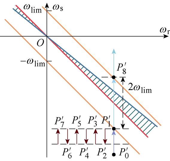
图3 反向主动零穿工况
Fig.3 Reversed low-frequency ride-through condition
 (13)
(13)
将式(9)代入式(13),可得
 (14)
(14)
结合式(12)中的励磁电流上、下确界,可知图2a中穿越点P7的励磁电流应满足
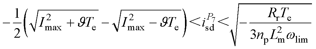 (15)
(15)
当励磁电流自适应变化至式(15)所示区间时,主动零频穿越策略使能,快速减小励磁电流,使电机运行工况点从P7点突变至P8点,完成主动零频穿越过程。
主动零频穿越策略使能瞬间,瞬态转矩满足
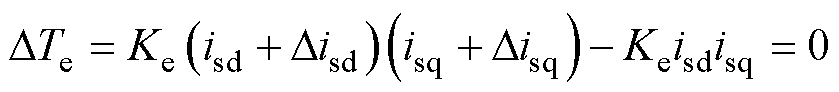 (16)
(16)
当励磁电流自适应变化,电流环与转速环共同作用使转矩电流随之改变,考虑到电流限制
 (17)
(17)
联立式(16)与式(17)可得励磁电流修正步长为
 (18)
(18)
当同步转速维持在限制值wlim时,电机转矩电流与励磁电流之比也将维持在确定的限制值,即
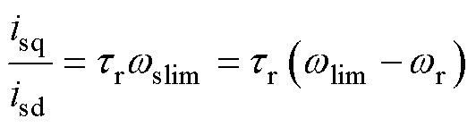 (19)
(19)
式中,wlim为转子转速恒定、同步转速限制值确定时的转差转速限制值。
式(19)说明励磁电流自适应变化且转子转速恒定时,由于设置了确定的同步转速限制值,转矩电流与励磁电流比值恒定,定子电流矢量将由于主动零频穿越策略的作用反复旋转至同一条直线上,即图2b中点P1-P3-P5-P7连接而成的直线。
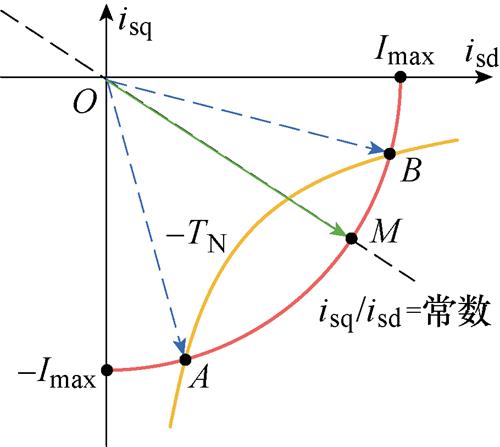
图4 主动零频穿越电流限制分析
Fig.4 Current limit analysis of the PLFRT method
对于实际的感应电机控制系统,其励磁电流和转矩电流必须满足电流限制
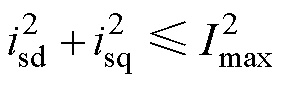 (20)
(20)
式中,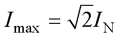 ,IN为感应电机额定电流。
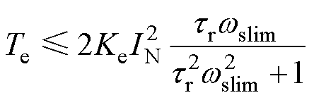
当感应电机同步转速限制值选定,转矩电流与励磁电流之比也随之确定。结合电磁转矩计算式(10),受限于定子电流基本不等式(当且仅当isd= isq时等号成立),即
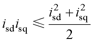 (21)
(21)
若同步转速限制值选择不合理,会导致转矩电流与励磁电流之比过大/过小,从而在发电负载变化、主动零频穿越策略作用下弱化感应电机的带载能力。在图4中,当电机定子电流矢量增加至电流限制圆时(见图4中M点),系统达到转矩输出能力极限。图4中M点输出转矩为
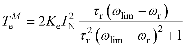 (22)
(22)
为探究不同转子转速和同步转速限制值对感应电机带载能力的影响,使用式(19)中转差转速限制值wslim代入式(22),可得电机稳态带载能力极限为
 (23)
(23)
基于式(23),图5给出不同转速与不同同步转速限制值下电机的稳态带载能力极限。为保证电机在发电负载变化、主动零频穿越策略使能时拥有额定带载能力,同步转速限制值可行域在图5中标注。主动零频穿越策略中使用的同步转速限制值根据该可行域进行选取。
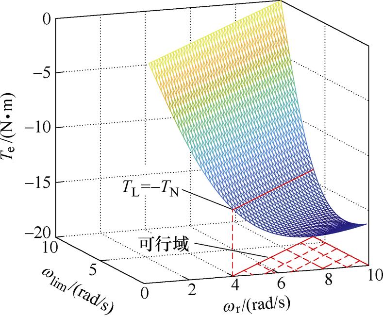
图5 满足额定负载的同步转速限制值与转子转速取值范围
Fig.5 The feasible region of synchronous speed limitation and rotor speed to meet rated load
电机实际转矩电流与励磁电流指令值之间的传递函数 [19]为
[19]为
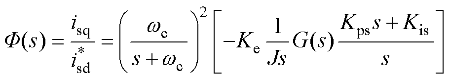 (24)
(24)
其中
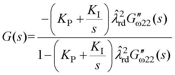
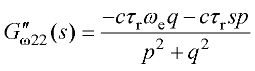
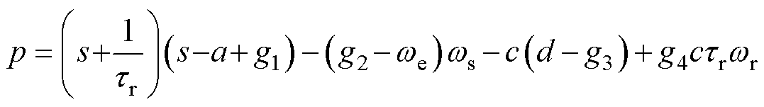
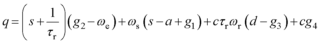
作为一个强耦合、非线性系统,感应电机电流内环响应速度远大于转速外环响应速度[21],其励磁电流与转矩电流无法同步改变。据式(24)计算可知感应电机转矩电流实际值与励磁电流之间存在相位延迟,且延迟的具体数值与励磁电流指令值变化的频率有关,严重时可能造成电机的电磁转矩与负载转矩失配而失稳。图6所示为电磁转矩不变工况下,通过Simulink仿真得到的励磁电流自适应变化时的转矩电流理论值isq_theo与转矩电流实际值isq对比图。据图6可知,励磁电流自适应变化时,转矩电流实际值与理论值之间存在相位延迟。
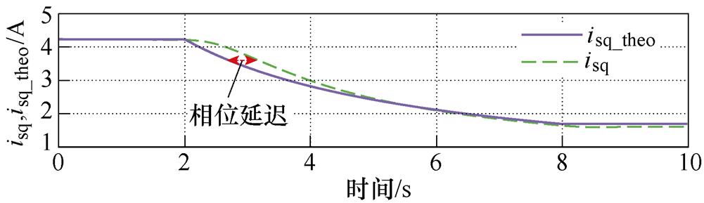
图6 转矩电流相位延迟仿真示意图
Fig.6 The phase delay of the torque current
为解决转矩电流相位延迟问题,本文提出一种转矩电流相位补偿方法,令
 (25)
(25)
式中, 为相位补偿后的转矩电流指令值;
 为相位补偿前的转矩电流指令值;
 为实际电机离散操作系统中每一拍的转矩电流相位补偿值,且
 (26)
(26)
式中, 为动态相位补偿值;
 为转矩电流变化斜率;
 为励磁电流指令值变化斜率的等效频率。式(26)所示的转矩电流相位补偿值可通过三角形原理计算得到。
通过式(25)与式(26)所示的转矩电流相位补偿方法,可以在线对转矩电流进行动态相位补偿,减小电机实际转矩电流与励磁电流指令值之间的相位延迟,满足电磁转矩与负载转矩实时匹配,保证主动零穿过程中系统带载时的稳定性。该方法的有效性通过下一节零穿过程优化实验进行验证。
为验证本文所提出主动零频穿越策略的有效性,使用基于意法半导体ARM STM32F103的2.2 kW感应电机实验平台进行实验,实验平台所用电机额定参数见表1。
2.2 kW感应电机实验平台如图7所示。该平台包括两台参数相同的2.2 kW笼型感应电机。负载侧电机工作在转矩控制模式,提供实验所需电动或发电负载;感应电机工作在矢量控制模式,通过输入转子转速指令值测试所提算法的有效性。变频器中PWM开关频率设置为6 kHz。为实现主动零频穿越策略中对励磁电流的自适应修正,初始励磁电流设置为40 %额定电流。
表1 2.2 kW感应电机参数
Tab.1 2.2 kW IM parameters
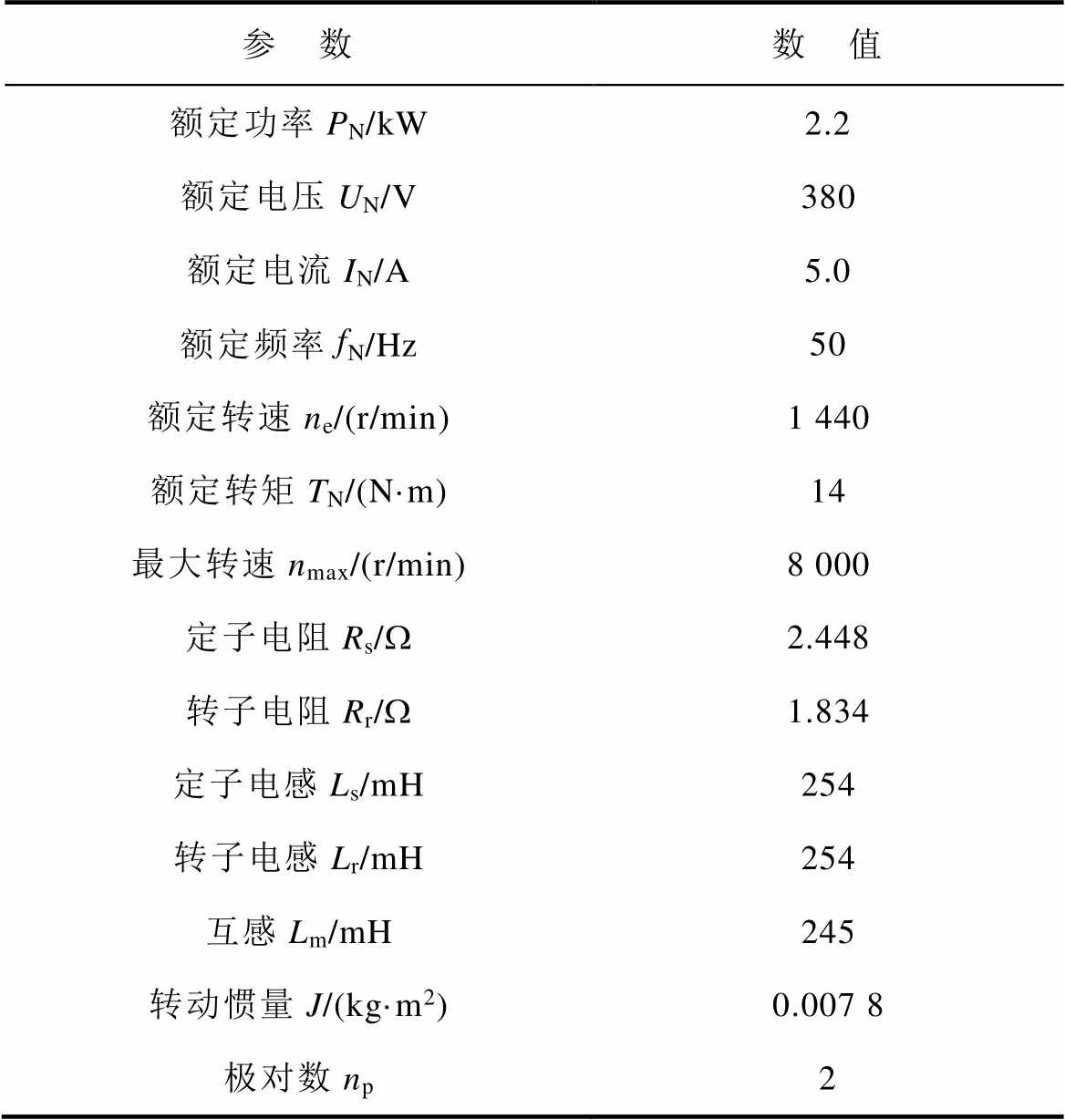
参 数数 值 额定功率PN/kW2.2 额定电压UN/V380 额定电流IN/A5.0 额定频率fN/Hz50 额定转速ne/(r/min)1 440 额定转矩TN/(N·m)14 最大转速nmax/(r/min)8 000 定子电阻Rs/W2.448 转子电阻Rr/W1.834 定子电感Ls/mH254 转子电感Lr/mH254 互感Lm/mH245 转动惯量J/(kg·m2)0.007 8 极对数np2
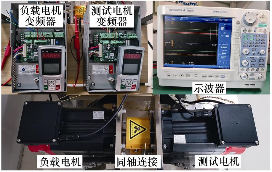
图7 2.2 kW感应电机实验平台
Fig.7 2.2 kW IM experimental setup
为模拟工业负载实际变化工况,检验本文所提方法在励磁电流自适应变化以及零频穿越阶段的控制性能,测试主动零频穿越策略在发电负载变化下对维持电机控制系统稳定的有效性,本节进行零频穿越对比实验。设置发电负载恒速率增加,从0 N·m到-8 N·m的时间设定为70 s,转速指令设为恒定值60 r/min,分别在无主动零频穿越策略和有主动零频穿越策略两种控制算法下进行实验。
图8所示为发电负载变化下不采用主动零频穿越策略的实验结果。随着发电负载不断增大,在恒定转速下,电机同步转速不断减小,当电机运行至不稳定区域内,转速观测失败。图8实验结果说明,不采用主动零频穿越策略,当发电负载变化至较大值时,即使采用反馈矩阵,电机仍会失稳。
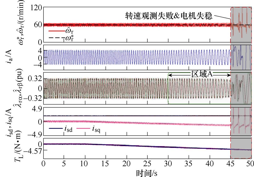
图8 发电负载变化下无主动零频穿越策略对照实验
Fig.8 Experimental results without PLFRT method under variable regeneration load
为保证无速度传感器感应电机矢量控制系统在穿越低速发电区域与定子电流零频区域时转速可观测,采用2.2节提出的主动零频穿越策略,实验结果如图9所示。考虑到3.1节中所述电机带载能力限制,同步转速限制值wlim设置为1 Hz。
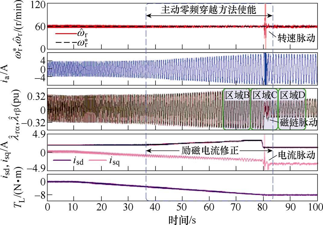
图9 发电负载变化下主动零频穿越策略验证实验
Fig.9 Experimental results with PLFRT method under variable regeneration load
图9所示实验中,当感应电机同步转速随发电负载增大而降低至2.2节中所述限制值时,使能主动零频穿越策略,自适应修正励磁电流,使同步转速始终维持在不稳定区域之外。当励磁电流达到2.3节中式(15)所述合适的零穿区间,快速减小励磁电流指令值,电机运行点从P7点阶跃变化至P8点,完成主动零穿过程。对比无主动零频穿越策略的图8可知,虽然图9中主动零穿瞬间估计转速和相电流、估计磁链、转矩电流存在脉动现象,但主动零穿过程中转速全程可观测。
将图8和图9中区域A、B、D的估计磁链轨迹绘于图10中。区域A为图8中电机运行工况点进入不稳定区域后40 s内的估计磁链;区域B为图9中主动零穿前10 s内的估计磁链;区域D为图9中主动零穿后10 s内的估计磁链。对比可知,无主动零频穿越策略时,当电机运行工况点进入不稳定区域时,区域A估计磁链随即发散;主动零频穿越策略使能时,区域B和区域D中,估计磁链稳定可观测。
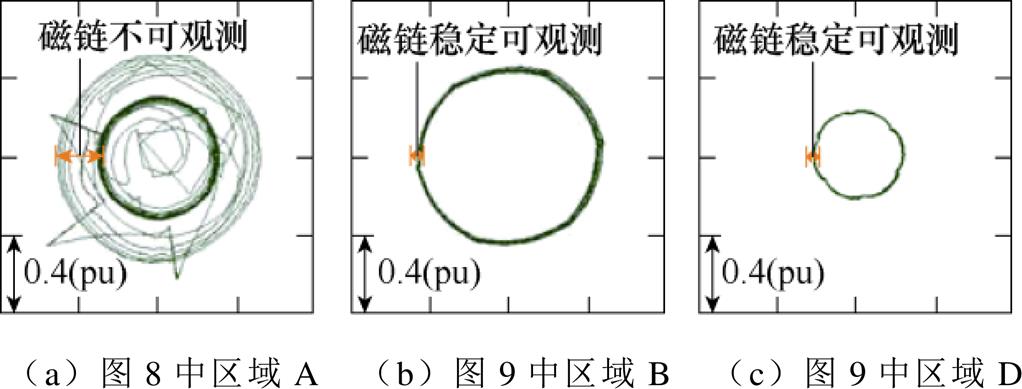
图10 图8和图9中主动零穿策略应用前后估计磁链轨迹对比
Fig.10 Comparison of estimated rotor flux trajectories using the results in Fig.8 and Fig.9
为抑制主动零频穿越策略带来的电流、转速和磁链脉动问题,检验3.2节提出的转矩电流相位补偿方法的有效性,本节应用转矩电流相位补偿方法进行零穿过程优化实验,并对比有无优化前后估计磁链轨迹和电流矢量轨迹。
零穿过程优化实验结果如图11所示。在主动零频穿越过程中应用转矩电流相位补偿方法,保证转矩电流及时响应被快速修正的励磁电流,以优化零频穿越过程。可以看出,相比于没有应用转矩电流相位补偿方法的图9实验结果,转子转速、估计磁链、转矩电流的脉动情况得到明显改善,电流保持在电流限制内,且运行工况点成功穿越了定子电流零频区域。零频穿越期间电机始终稳定运行,转子转速和估计磁链均保持良好的可观测性。

图11 零穿过程优化实验结果
Fig.11 Experimental results with optimized PLFRT method
图12所示为零频穿越过程的10 s时间中,应用转矩电流相位补偿方法与否的估计磁链轨迹。对比可知,图9区域C中估计磁链虽然能在零穿前后保持可观测,但在励磁电流快速变化前后,磁链轨迹有一定的发散趋势,过渡过程存在波动;图11区域E中估计磁链在励磁电流快速变化前后始终保持良好的可观测性,且在定子电流零频穿越瞬间(即图中圆心部分)平滑过渡,验证了转矩电流相位补偿方法对电机零穿过程优化的有效性。
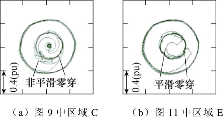
图12 图9和图11中零穿过程优化前后估计磁链轨迹对比
Fig.12 Comparison of estimated rotor flux trajectories using the results in Fig.9 and Fig.11
零频穿越过程优化前后,定子电流矢量轨迹如图13所示。图13中初始励磁电流为40 %IN,随发电负载增加,转矩电流增加,电流矢量向下延伸;当电机同步转速达到其限制值,主动零频穿越策略使能,电流矢量反复旋转且落在同一直线上,与3.1节中分析保持一致;当励磁电流达到零穿区间时,励磁电流快速减小,电流矢量旋转至低励磁电流、高转矩电流区域。与图13a相比,图13b中优化后的电流矢量在零穿过程中始终保持在电流限制内。
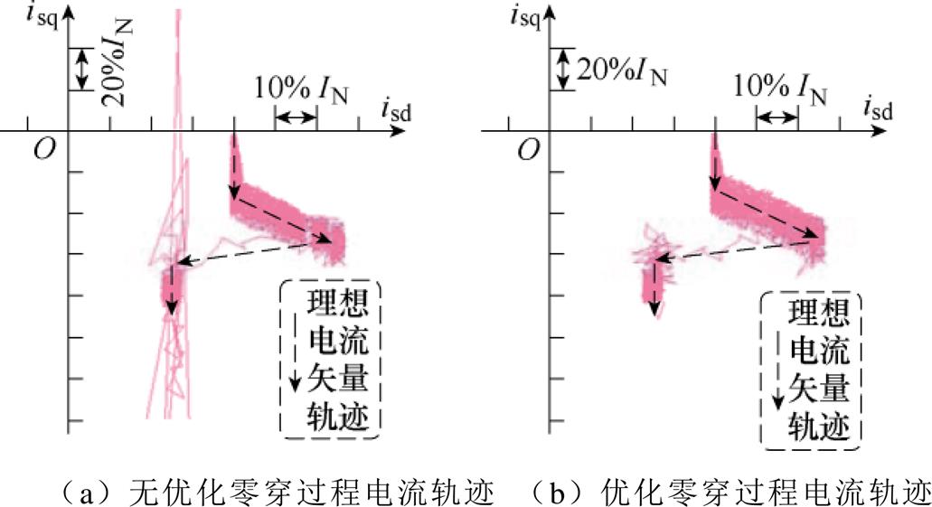
图13 定子电流矢量轨迹
Fig.13 Stator current vector trajectories
本文提出了一种负载变化下无传感器感应电机主动零频穿越及脉动抑制策略。与无零频穿越策略实验相比,所提出的励磁电流自适应修正方法可以有效提高在定子电流低频乃至零频区域转速的可观测性。针对主动零穿策略带来的转速/磁链/电流脉动等问题,提出了一种转矩电流相位补偿方法,通过在线计算转矩电流相位补偿值,使电磁转矩与负载实时匹配。实验表明,与传统方法相比,该方法可以保证主动零频穿越过程中系统带载时的稳定性,并有效抑制主动零频穿越策略带来的脉动 问题。
参考文献
[1] 梅杨, 易高. 间接矩阵变换器-异步电机调速系统模型预测控制权重系数自整定方法[J]. 电工技术学报, 2020, 35(18): 3938-3948.
Mei Yang, Yi Gao. A weighting factor self-tuning method in model prediction control for indirect matrix converter with induction motor system[J]. Transa- ctions of China Electrotechnical Society, 2020, 35(18): 3938-3948.
[2] 谢仕宏, 孟彦京, 高钰淇, 等. 小电容变频器及感应电机回馈能量分析[J]. 电工技术学报, 2020, 35(4): 734-744.
Xie Shihong, Meng Yanjing, Gao Yuqi, et al. Analysis about small capacitor frequency converter and feedback energy of induction motors[J]. Transa- ctions of China Electrotechnical Society, 2020, 35(4): 734-744.
[3] 陆文斌, 姚文熙, 吕征宇. 基于改进闭环磁链观测器的感应电机无速度矢量控制[J]. 电工技术学报, 2013, 28(3): 148-153.
Lu Wenbin, Yao Wenxi, Lü Zhengyu. Speed sensor- less vector control with improved closed-loop flux observer for induction machines[J]. Transactions of China Electrotechnical Society, 2013, 28(3): 148- 153.
[4] 于泳, 蒋生成, 王高林, 等. 基于状态观测器的感应电机速度传感器故障诊断及容错控制[J]. 中国电机工程学报, 2012, 32(18): 123-130, 186.
Yu Yong, Jiang Shengcheng, Wang Gaolin, et al. Fault diagnosis and tolerant control for speed sensors based on state observers in induction motor drives[J]. Proceedings of the CSEE, 2012, 32(18): 123-130, 186.
[5] 王勃, 王天擎, 于泳, 等. 感应电机电流环非线性积分滑模控制策略[J]. 电工技术学报, 2021, 36(10): 2039-2048.
Wang Bo, Wang Tianqing, Yu Yong, et al. Nonlinear integral sliding mode control strategy for current loop of induction motor drives[J]. Transactions of China Electrotechnical Society, 2021, 36(10): 2039- 2048.
[6] 李筱筠, 杨淑英, 曹朋朋, 等. 低速运行时异步驱动转速自适应观测器稳定性分析与设计[J]. 电工技术学报, 2018, 33(23): 5391-5401.
Li Xiaojun, Yang Shuying, Cao Pengpeng, et al. Analysis of the stability of speed adaptive observer and its design for induction motor drive at low speeds[J]. Transactions of China Electrotechnical Society, 2018, 33(23): 5391-5401.
[7] 宋文祥, 周杰, 朱洪志, 等. 基于自适应全阶观测器的感应电机低速发电运行稳定性[J]. 电工技术学报, 2014, 29(3): 196-205.
Song Wenxiang, Zhou Jie, Zhu Hongzhi, et al. Regenerating-mode stabilization of induction motors based on adaptive full-order observer[J]. Transactions of China Electrotechnical Society, 2014, 29(3): 196- 205.
[8] 陈闯, 王勃, 于泳, 等. 基于改进指数趋近律的感应电机滑模转速观测器研究[J]. 电工技术学报, 2020, 35(增刊1): 155-163
Chen Chuang, Wang Bo, Yu Yong, et al. An improved exponential reaching law based-sliding mode observer for speed-sensorless induction motor drives[J]. Transactions of China Electrotechnical Society, 2020, 35(S1): 155-163.
[9] Sun Wei, Gao Jie, Yu Yong, et al. Robustness improvement of speed estimation in speed-sensorless induction motor drives[J]. IEEE Transactions on Industry Applications, 2016, 52(3): 2525-2536.
[10] Qu Zengcai, Hinkkanen M, Harnefors L. Gain scheduling of a full-order observer for sensorless induction motor drives[J]. IEEE Transactions on Industry Applications, 2014, 50(6): 3834-3845.
[11] 吕英俊, 刘卓伟, 苏涛, 等. 异步电机无传感器矢量控制极低速与零速性能研究[J]. 中国电机工程学报, 2019, 39(20): 6095-6103, 6190.
Lü Yingjun, Liu Zhuowei, Su Tao, et al. Research of sensorless vector control performance for induction motor at very low-speed and zero-speed[J]. Pro- ceedings of the CSEE, 2019, 39(20): 6095-6103, 6190.
[12] Luo Cheng, Wang Bo, Yu Yong, et al. Operating- point tracking method for sensorless induction motor stability enhancement in low-speed regenerating mode[J]. IEEE Transactions on Industrial Electronics, 2020, 67(5): 3386-3397.
[13] Chen Jiahao, Huang Jin. Globally stable speed- adaptive observer with auxiliary states for sensorless induction motor drives[J]. IEEE Transactions on Power Electronics, 2019, 34(1): 33-39.
[14] Vaclavek P, Blaha P, Herman I. AC drive obser- vability analysis[J]. IEEE Transactions on Industrial Electronics, 2013, 60(8): 3047-3059.
[15] 王震宇, 孙伟, 蒋栋. 基于虚拟电压注入的闭环磁链观测器的感应电机无速度传感器矢量控制系统[J]. 电工技术学报, 2022, 37(2): 332-343.
Wang Zhenyu, Sun wei, Jiang Dong. Induction motor speed sensorless vector control system based on closed-loop flux observer with virtual voltage injection[J]. Transactions of China Electrotechnical Society, 2022, 37(2): 332-343.
[16] Wang Zhenyu, Sun Wei, Jiang Dong. Stability analysis and trajectory design of a nonlinear switching system for speed sensorless induction motor drive[J]. IEEE Transactions on Industrial Electronics, 2022, 69(6): 5514-5524.
[17] Luo Cheng, Wang Bo, Yu Yong, et al. Enhanced low-frequency ride-through for speed-sensorless induction motor drives with adaptive observable margin[J]. IEEE Transactions on Industrial Elec- tronics, 2021, 68(12): 11918-11930.
[18] Yin Shaobo, Huang Yingwei, Xue Yaru, et al. Improved full-order adaptive observer for sensorless induction motor control in railway traction systems under low-switching frequency[J]. IEEE Journal of Emerging and Selected Topics in Power Electronics, 2019, 7(4): 2333-2345.
[19] 罗成. 无速度传感器感应电机低速运行及零频穿越策略研究[D]. 哈尔滨: 哈尔滨工业大学, 2021.
[20] Luo Cheng, Li Ruhan, Yang Kai, et al. Graphical multiple-error feedback matrix design for stability and robustness enhancement of speed-sensorless induction motor drives[J]. IEEE Transactions on Industrial Electronics, 2023, 70(4): 3537-3548.
[21] Wang Bo, Huo Zhixin, Yu Yong, et al. Stability and dynamic performance improvement of speed adaptive full-order observer for sensorless induction motor ultralow speed operation[J]. IEEE Transactions on Power Electronics, 2020, 35(11): 12522-12532.
Abstract In recent years, the sensorless induction motor drives (SIMD) technique has seen significant advances in industrial applications and electrical transmission systems. Compared to sensor-based control strategies, the SIMD technique has low cost, high reliability, and increased resistance to harsh environments. Conventional approaches of SIMD, such as model reference adaptive system, extended Kalman filter, sliding mode observer, and full-order flux observer, nonetheless, fail to estimate the rotor speed stably in the low-speed regenerating mode. Therefore, a proactive low-frequency ride-through (PLFRT) method and its ripple reduction technique for sensorless induction motor drives under load variation are proposed in this paper.
Firstly, based on the determinant analysis of the error coefficient matrix, the instability of the IM in low-speed regenerating mode is analyzed. The influence of load variation on IM is revealed. With constant magnetizing current under changing load conditions, two problems exist: speed unobservability and poor system stability. Thus, the PLFRT method is introduced. At a fixed moment, the electromagnetic torque keeps constant. The change of the magnetizing current means the synchronous change of the torque current and the slip speed. Therefore, The PLFRT method can modify the magnetizing current reference and then the synchronous speed will be prevented from the unstable region. When the synchronous speed reaches the preset limit, the PLFRT method will be triggered, and the current reference will be modified. Then speed observability is ensured during the crossing process. The adaptive increase of the magnetizing current reference will be triggered automatically and repeatedly until the IM is in the appropriate range to cross the low-frequency region. The adaptive variation interval of magnetizing current and its correction step length are derived based on the stator current limit.
The influence of synchronous speed limit is studied to enhance the torque output capacity of the sensorless IM control system. The stator current limit with the implemented PLFRT method is discussed, and the value range of the synchronous speed limit is also given. The suggested selection of the limit value is presented. In the real induction motor system, an inevitable phase delay exists between the magnetizing current and torque current. Hence, the currents cannot change simultaneously, leading to a mismatch between the electromagnetic torque and the load. Such problems occur with ripples of rotor speed, estimated flux, and great torque overcurrent. A torque current phase compensation method is developed to ensure real-time matching of the electromagnetic torque and the load. In the discrete system, the amplitude of the torque current is added in every beat to meet the theoretical value to suppress the ripples of speed, flux, and current during zero-frequency ride-through.
The effectiveness of the proposed method is validated on a 2.2 kW induction motor experimental setup. Performance with conventional and the PLFRT method under variable regenerating load is presented. Although the ripples exist, comparative experiments demonstrate that the PLFRT method can cross the zero- stator-frequency line successfully. Then, the torque current compensation method is applied in the experiments. The ripples and the overcurrent of the torque current are decreased. Furthermore, the estimated flux trajectory of the SIMD system with the PLFRT method enabled keeps convergent and observable during the crossing process.
keywords:Induction motor, sensorless control, low frequency ride-through, ripple reduction
DOI: 10.19595/j.cnki.1000-6753.tces.221286
中图分类号:TM346
国家自然科学基金(52237002, 52207055)、中国博士后科学基金(2022M721232)、湖北省重点研发计划(2022BAA097, 2022BAA100)资助项目。
收稿日期 2022-06-30
改稿日期 2022-07-24
杨 凯 男,1976年生,教授,博士生导师,研究方向为交流电机设计及其智能控制技术。E-mail: yk@hust.edu.cn
罗 成 男,1991年生,博士,助理研究员,研究方向为交流电机控制技术。E-mail: luoxcheng@126.com(通信作者)
(编辑 郭丽军)