 (1)
(1)
摘要 针对精密直驱XY运动平台在执行加工任务时,易受到系统不确定性动力学及双轴协调匹配性的影响而产生轮廓误差的问题,提出一种基于参考调整轮廓误差(RACE)模型和不确定性补偿器(UC)的自适应非线性滑模轮廓控制(ANSMCC)方法。由于传统的将跟踪误差法向分量视作近似轮廓误差的方法并不适用于大曲率轮廓加工轨迹,因此,建立参考调整坐标系,通过坐标变换的方式计算得出更为精准的RACE模型。采用ANSMCC方法对轮廓误差进行控制,通过设计非线性滑模面可以有效提高系统的动态响应速度和轮廓跟踪精度。为进一步减小参考模型与实际对象之间的误差,设计UC对不确定性动力学进行补偿,从而提高系统的鲁棒性。实验结果表明,该方法能够有效克服直驱XY平台系统中不确定性动力学的影响,提高轮廓加工精度。
关键词:直驱XY运动平台 参考调整轮廓误差 不确定性补偿器 自适应非线性滑模轮廓控制 轮廓加工精度
工业机器人和电子制造装备产业的飞速发展对数控装置的精度和速度提出了更高的要求。直驱XY运动平台可实现多轴高档数控机床在XY坐标系的运动,具有响应速度快、加工精度高的优点,是实现精密轮廓控制的关键部件[1]。然而,由于直驱XY平台采用两台永磁直线同步电机作为动力源,系统中存在的非线性动力会不经过传动环节衰减而直接影响到平台的运动[2]。此外,运动过程中两个进给驱动轴的匹配和协调性问题也会降低系统的轮廓加工精度[3]。为此,解决轮廓精密跟踪控制难题是当前多轴机械加工行业的重要任务。
在实际加工过程中,直驱XY运动平台完成的加工轨迹是两轴电机协调运动的结果,因此,工件表面的质量取决于轮廓误差。然而,对于自由且复杂的轮廓加工轨迹而言,建立实时精确的轮廓误差模型较为困难。因此,国内外学者转而采用具有较高计算精度和实时性的近似等效轮廓误差模型[4]。文献[5]在任务坐标系下,将跟踪误差的法向分量视作轮廓误差,虽然该方法计算简单,但当轮廓轨迹曲率较大时,估计并不准确。文献[6]利用系统的位置跟踪误差和进给率等信息设计了轮廓误差估计器,能够实时有效计算轮廓误差。文献[7]在极坐标下建立了直驱XY平台的极坐标轮廓误差非线性模型,但这种建模方法较为复杂。
基于轮廓误差模型,轮廓控制器的设计也有益于轮廓精度的提高。文献[8]采用伪微分反馈位置控制确保系统对不确定性的鲁棒性,利用切向轮廓误差补偿减小轮廓误差,但该方法在复杂轮廓曲线下的轮廓跟踪精度有待提高。文献[9]将基于超螺旋滑模控制的等效误差轮廓控制器应用到直线电机精密运动平台,克服了摩擦力和负载扰动,提高了轮廓跟踪精度,但其并未考虑参数变化对系统的影响。文献[10]重新定义了直驱平台的融合误差,设计了自适应全局滑模轮廓控制器,有效减小了轮廓跟踪误差,但该方法仅验证了椭圆轨迹下的轮廓跟踪情况,对复杂大曲率曲线的适用性有待进一步研究。
因此,针对上述问题,本文提出一种能够实时精确计算的参考调整轮廓误差(Reference Adjust- ment Contour Error, RACE)模型,并基于此模型设计了自适应非线性滑模轮廓控制(Adaptive Non- linear Sliding Mode Contour Control, ANSMCC)方法,能够保证系统在具有快速动态响应速度的同时,减小轮廓跟踪精度。同时,设计不确定性补偿器(Uncertainty Compensator, UC)减小参考模型与实际对象之间的误差,补偿不确定性动力学对轮廓精度的影响。最后,在直驱XY运动平台上开展实验,实验结果表明,所提出的方法能够有效提高系统的鲁棒性,改善直驱XY运动平台在执行大曲率轮廓加工任务时的轮廓跟踪精度。
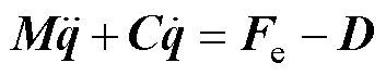
直驱XY平台的动态方程表示[11]为
(1)
式中, 为直驱XY平台中直线电机的动子位置,
 ;
; 为动子质量,
 ;下角标x和y分别表示X轴电机和Y轴电机;
 为粘滞摩擦系数,
 ;
; 为系统总不确定性动力学,
 ,包括参数变化、外部扰动和摩擦力等;
 为电机电磁推力,
 ,表示为
,表示为
 (2)
(2)
式中, 为电磁推力系数,
 ;
; 为q轴电流,
 。
。
结合式(2),可将式(1)改写为
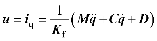 (3)
(3)
式中, 为系统总控制输入,
 。
。
因此,根据式(1)~式(3),并以X轴电机为例,X轴电机实际系统简化框图如图1所示。
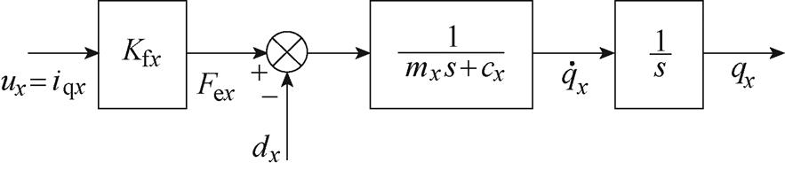
图1 X轴电机实际系统简化框图
Fig.1 Simplified block diagram of X-axis motor actual system
在直驱XY运动平台的加工应用中,由于工件的加工品质和轮廓误差的大小息息相关,为此轴间轮廓误差比单轴跟踪误差更重要。轮廓误差是指实际位置到期望轮廓之间的最短距离[12]。然而,当期望轮廓较为复杂时,很难直接获得实时轮廓误差值。为此,可以根据跟踪误差计算出等效轮廓误差。
图2为每个进给驱动轴的跟踪误差与系统轮廓误差示意图。图中, 为固定坐标系,其横纵轴分别为X和Y,代表直驱XY平台的两个进给驱动轴。在此坐标系下,曲线c表示由进给轴驱动平台的加工零件点的期望轮廓曲线;
 为在下t时刻期望位置,
 ;为实际位置;
 为轮廓误差,即到c之间的距离;
 为跟踪误差,是指和之间的差值,由每个进给驱动轴上的跟踪误差组成,表示为
 (4)
(4)
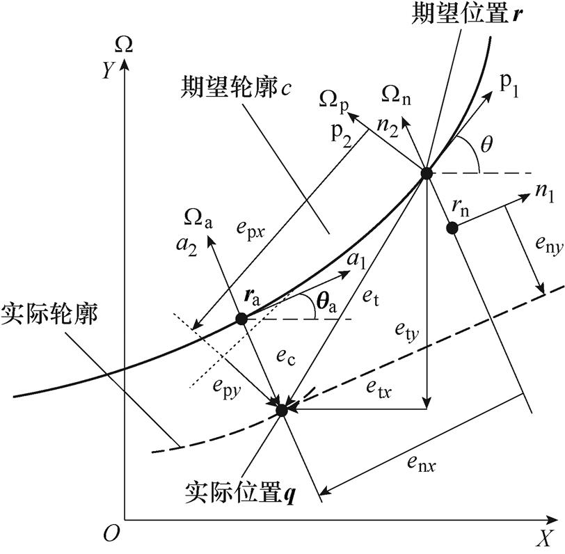
图2 跟踪误差与轮廓误差示意图
Fig.2 Schematic diagram of tracking error and contour error
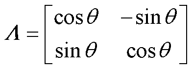
为根据求取出,建立如图2所示的局部坐标系 ,其轴
,其轴 在c处与相切,轴
 与垂直。通过坐标变换,可将坐标系下的转换到坐标系下,得
 (5)
(5)
其中
 (6)
(6)
式中, 为与之间的倾斜角;
 和
和 分别为期望轮廓轨迹在位置处跟踪误差的切向分量和法向分量。
通常,如文献[5]所示,可将跟踪误差法向分量视为实际轮廓误差的近似值,减小便可以提高轮性能。这种方法的优点在于,无需获取实际轮廓误差,可以避免通过反复迭代计算求取的复杂性,并且能独立调整和[13]。然而,当 较大时,采用近似估计并不准确,从图2中也可看出,和之间尚存在较大误差。
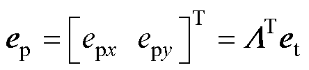
因此,基于坐标变换和等效轮廓误差思想,本文提出RACE方法。该方法通过建立图2中的 坐标系,推导出与相近的
 来近似等效,从而减少实际和近似轮廓误差之间的差异。
首先,建立坐标系 ,其坐标轴分别为
 和
和 ,其原点为
,其原点为 ,是期望轮廓曲线
 上距离点最近的位置,相对于的倾斜角为
 。假设沿位置和位置之间的轨迹所需速度几乎恒定,则通过该段所需的时间
 可估计为
可估计为
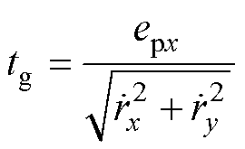 (7)
(7)
根据式(7),可得出和的估计值分别为
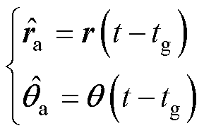 (8)
(8)
根据式(8),可得修正期望位置 表示为
表示为
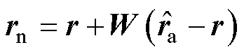 (9)
(9)
 (10)
(10)
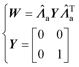
式中, 为在处旋转矩阵的近似值,通过将
 代入到式(5)和式(6)中求取。对求导可得
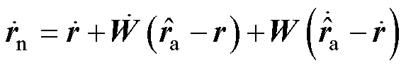 (11)
(11)
 (12)
(12)
与式(4)相同,可得在下,修正后的跟踪误差 为
为
 (13)
(13)
通过坐标变换,类比于式(5),可将坐标系下的转换到坐标系下,得
 (14)
(14)
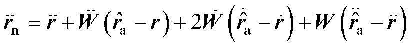
根据式(13),对式(14)求二阶导数,并应用旋转矩阵性质
 和
和
 ,得
,得
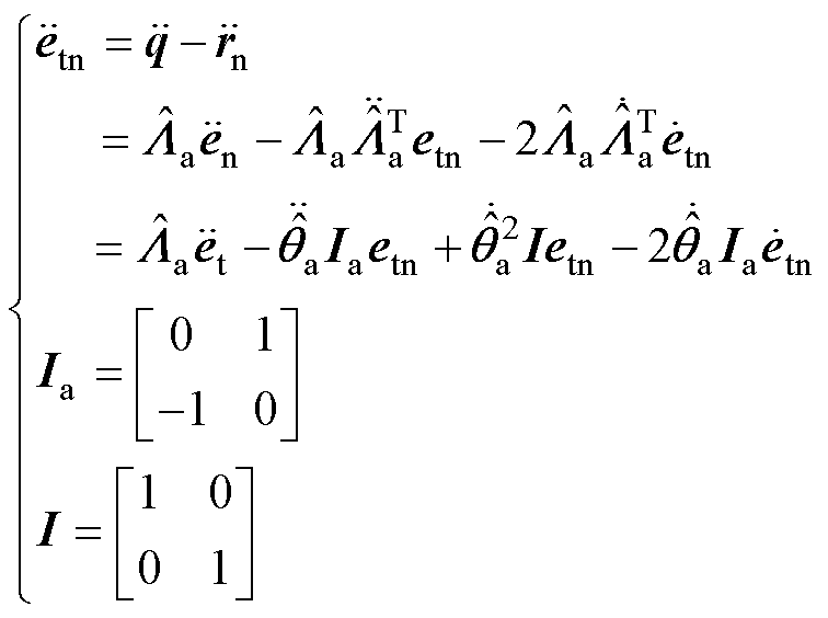 (15)
(15)
至此,采用代替轮廓误差,RACE模型设计完成。
由于直驱XY平台伺服系统在运行过程中会受到非线性动力学的影响,因此,在设计控制器时分别针对线性参考模型与非线性动力学部分设计ANSMCC方法和UC方法进行控制。
首先,根据式(3),忽略系统总不确定性动力学,则可得到直驱XY平台进给系统的线性参考模型为
 (16)
(16)
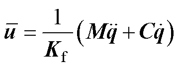
式中, 为线性参考模型的控制输入,
 ,作用于系统线性参考模型。
其次,考虑到系统实际模型中包含总不确定性动力学,因此设计UC来补偿其系统的影响,UC的控制输入为 ,因此,有
,因此,有
 (17)
(17)
因此,控制系统总体框图如图3所示。
设计滑模轮廓控制器时,需要设计合适的滑模面并选取控制律使系统状态点能够快速收敛到滑模面上[14]。传统滑模面的设计通常采用线性滑模面,但这种方法无法同时保证控制系统的快速响应性和小超调量。为此,在ANSMCC中,设计非线性滑模面为
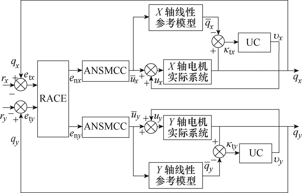
图3 控制系统总体框图
Fig.3 Overall block diagram of control system
 (18)
(18)
 (19)
(19)
式中, 为滑模面,
为滑模面, ;
; 为正定矩阵;
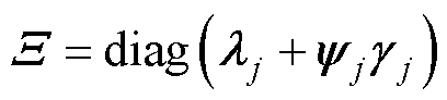
 为滑模面的线性增益,下角标j为X轴或Y轴;
 为对称正定矩阵,用于调整最终阻尼比;
 为与轮廓误差
 有关的非负可微非线性函数,其上界为
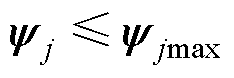 ,设计为
,设计为
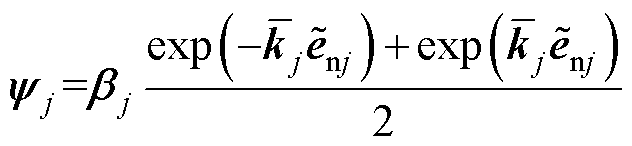 (20)
(20)
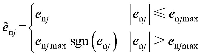 (21)
(21)
式中, 、
、 和
和 为正整定参数,和分别用于调整的最终阻尼比和变化率幅值;
 为误差信号
为误差信号 的符号函数。当系统状态点到达滑模面时,有
 ,则根据式(18),可得
 (22)
(22)
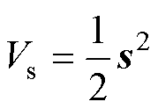
为证明控制系统的稳定性,选取Lyapounov函数为
 (23)
(23)
将式(22)代入式(23)并求导可得
 (24)
(24)
由于为正定矩阵,因此可得系统渐近稳定。
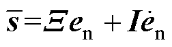
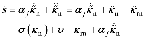
基于式(18)~式(21)设计的滑模面、式(16)所示的系统动态方程以及式(15),设计控制律为
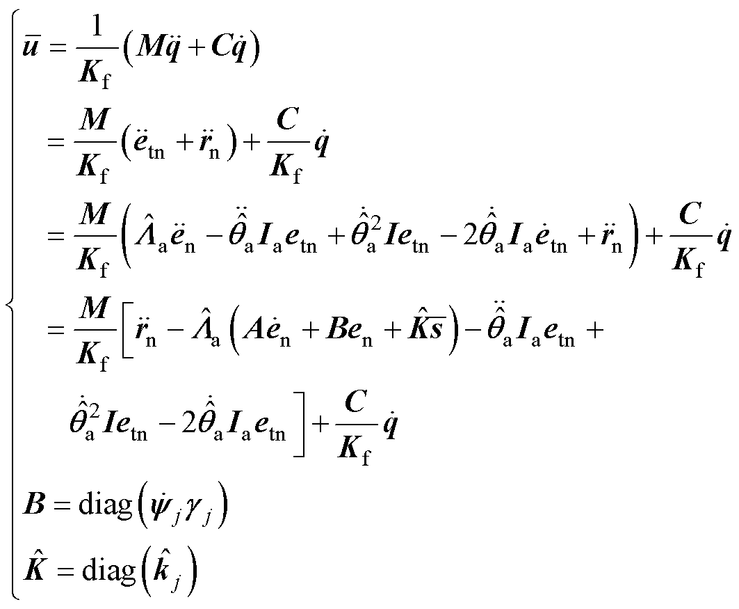 (25)
(25)
式中, 为自适应增益。设计自适应律为
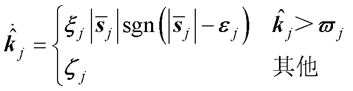 (26)
(26)
式中, 、
、 、
、 和
和 为正常数。
为正常数。
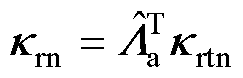
由于在设计ANSMCC时采用的是线性参考模型,导致实际对象与参考对象模型不同,即式(3)中的系统总不确定性动力学D仍然存在,因此设计了UC来补偿D,以进一步减小系统的轮廓跟踪误差。在固定坐标系下,定义模型不确定性误差为
 (27)
(27)
式中, 为实际位置与线性模型下的位置
 之间的差值。与式(14)相同,将
 从坐标系下转换到
 坐标系下,可得
 (28)
(28)
式中, 。当修正期望位置恰好为期望位置时,则有
 。假设
。假设 为二阶非线性动力学,则可表示为
 (29)
(29)
式中,为UC的控制输入信号; 为系统未知动态,且
 ,
, 为其最大值。
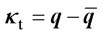
不确定性动力学的跟踪误差定义为
 (30)
(30)
式中, 、
、 分别为在和坐标系下的跟踪误差,
 ,
, ;
; 为期望值,
为期望值, 。
。
为消除不确定性动力学对系统的影响,利用线性滑模控制方法进行动态补偿。设计滑模面为
 (31)
(31)
式中, 为正常数对角矩阵,
 。对式(31)求导可得
 (32)
(32)
其中
定义Lyapounov函数为
 (33)
(33)
在 时,可求得
时,可求得
 (34)
(34)
式中, 为正常数对角矩阵,
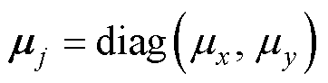 。
。
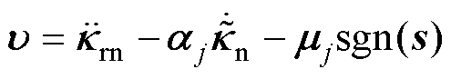
为抑制ANSMCC的抖振问题,采用饱和函数 替换式(34)中的符号函数[15]。利用边界层
 减小抖振,设计为
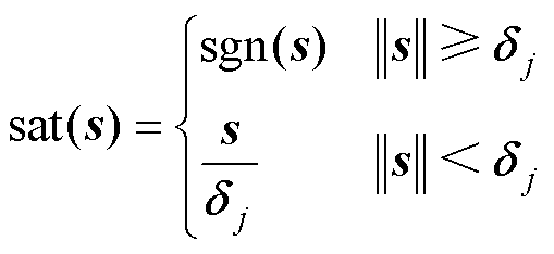 (35)
(35)
在实验中,控制算法通过DSP TMS320F28335系统应用到直驱XY运动平台的轮廓控制中。实验中,运动平台的额定电压为220 V、功率为1 500 W,经驱动环节转换为48 V电压进行控制,采样频率为4 kHz,直线光栅尺的分辨率为0.1 mm。系统硬件结构如图4所示。主要包括上位机PC、DSP控制器、直驱XY运动平台、传感器和光栅尺等部件。直驱XY运动平台的主要参数见表1。
为测试本文提出的轮廓控制方法的有效性,在如下三种轮廓控制方法下进行空载低速运行、空载高速运行和拖动负载运行三种对比实验:
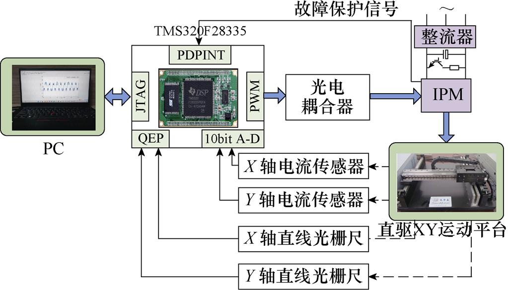
图4 基于DSP的直驱XY运动平台实验系统硬件结构
Fig.4 Hardware structure of direct drive XY motion platform experiment system based on DSP
表1 直驱XY运动平台主要参数
Tab.1 Main parameters of direct drive XY motion platform
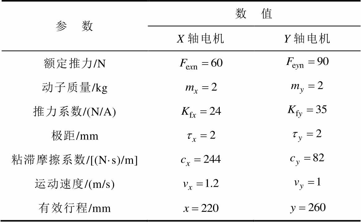
参 数数 值 X轴电机Y轴电机 额定推力/N 动子质量/kg 推力系数/(N/A) 极距/mm 粘滞摩擦系数/[(N·s)/m] 运动速度/(m/s) 有效行程/mm
(1)C1:基于传统轮廓误差模型的自适应滑模轮廓控制(Adaptive Sliding Mode Contour Control, ASMCC)方法,其中传统轮廓误差模型是指如文献[5]中的利用跟踪误差的法向分量近似轮廓误差的方法,ASMCC采用线性滑模面,即式(18)中滑模面的为常值不变,选取为 。
。
(2)C2:基于RACE模型的ANSMCC方法,其中RACE和ANSMCC均为本文所设计,利用C1与C2对比可以验证RACE和非线性滑模面的引入对于提高轮廓估计精度的有效性。
(3)C3:基于RACE和UC的ANSMCC方法,利用C2和C3对比来验证UC对于不确定性动力学的补偿效果。
为保证对比实验的公平性,C2和C3组实验中的ANSMCC选取为同样参数,所有的参数均通过反复调试,最终选择合适的参数以满足系统的动态和静态性能。边界层的设置主要是用于减小滑模控制的抖振,在调试过程中发现,边界层厚度越大,系统的精度下降,但鲁棒性增强;反之边界层小时,跟踪精度得到提升,抖振明显减小,但抗干扰能力有所下降。依照此原则,最终选取边界层厚度为 。在非线性滑模面设计时,主要包含线性增益和非线性函数的选取,通过调整系统阻尼比平衡系统的响应速度和跟踪精度,最终选取
 ,
, ,
, ;
; 。对于式(26)中自适应增益的选取,引入
 是为保证自适应增益的正值,且当
 时
时 减小,这意味着增益将保持在最小水平,同时满足
 的要求精度,为此,经反复调试,自适应律选取为
 、
、 、
、 、
、 。对于C3组中的UC,其主要用于对系统中不确定非线性的补偿控制,若选取参数过大,补偿作用大,易造成系统的不稳定甚至发散,为此,参数选取为
 、
、 。
。
在实验①中,命令直驱XY平台在低速情况下跟踪椭圆形期望轨迹,且在空载条件下进行实验。X轴输入为幅值20 mm、周期4 s的正弦信号,Y轴输入为幅值15 mm、周期4 s的余弦信号。采用C1、C2和C3三种方法控制下的椭圆轮廓跟踪曲线如图5所示,可见三种方法均可以较好地跟踪参考轮廓,而采用C3方法的轮廓跟踪曲线更接近于参考轨迹。图6为椭圆期望轨迹下,采用C1、C2和C3三种方法控制的轮廓跟踪误差曲线。对比图6中的C1和C2可以比较直观地看出,在空载条件下,由于采用所设计的RACE模型并在轮廓控制时引入非线性滑模面,C2的轮廓误差比C1的轮廓误差减小了约55.6%,轮廓误差约在±2.0 mm之内,这表明采用RACE可以更为准确地计算轮廓误差。此外,对比C1和C2曲线的初始响应时刻,可以发现,在采用非线性滑模面之后,系统的响应速度得到明显提升,这是由于非线性滑模面的设计可以调节系统阻尼比,从而平衡响应速度和跟踪精度。对比C2和C3可以看出,采用UC来补偿不确定性动力学对系统的影响效果较为明显,能够有效减小轮廓跟踪误差,提高轮廓加工精度。

图5 椭圆轮廓跟踪曲线
Fig.5 Contour tracking curves of ellipse
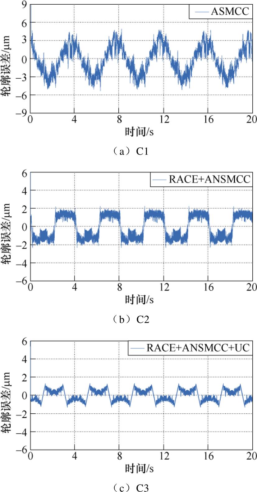
图6 低速跟踪椭圆期望轨迹轮廓误差曲线
Fig.6 Contour error curves of low speed tracking ellipse expected trajectory
为验证直驱XY运动平台在高速运动情况下的轮廓跟踪性能,进行实验②与实验①对比。X轴输入为幅值80 mm、周期1 s的正弦信号,Y轴输入为幅值50 mm、周期1 s的余弦信号。高速跟踪椭圆期望轮廓误差曲线如图7所示。对比图6和图7可以看出,在高速运动时,三种控制方法的轮廓跟踪性能稍有下降,但仍可以较好地跟踪期望轨迹。其中C1方法下的轮廓误差约在-7.8~7.2 mm之间波动,在通过RACE进行轮廓误差估计之后,系统的轮廓误差有效减小,约为±4.5 mm,这表明引入RACE对于轮廓性能提高的有效性。此外,对比图7b和图7c可以看出,UC对于不确定性的补偿效果较好,有利于提高系统的轮廓跟踪精度。因此,通过实验②结果可以得出,本文设计的减小轮廓误差的方法对于高速运动的直驱XY运动平台依然有效可行。
(a)C1
(b)C2
(c)C3
图7 高速跟踪椭圆期望轨迹轮廓误差曲线
Fig.7 Contour error curves of high speed tracking ellipse expected trajectory
实验③中,命令直驱XY平台跟踪大曲率的四叶草期望轨迹,且拖动1 kg负载进行实验,加载方式是通过在运动平台的上层Y轴直线电机的动子上叠放重物的形式来实现的,如图8所示。为分析加载后两台直线电机的跟踪情况,给出采用C3方法控制的X、Y轴电机的位置跟踪误差曲线和q轴电流曲线分别如图9和图10所示。观察两图可以发现,X轴电机的跟踪误差约为±1.8 mm,q轴电流约为5 A。在拖动负载时,Y轴的位置跟踪误差和电流同X轴相比稍有增大,但采用C3方法的单轴位置跟踪精度仍然满足系统单轴跟踪性能要求。
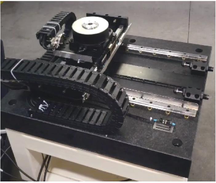
图8 加载示意图
Fig.8 Diagram of how to add load
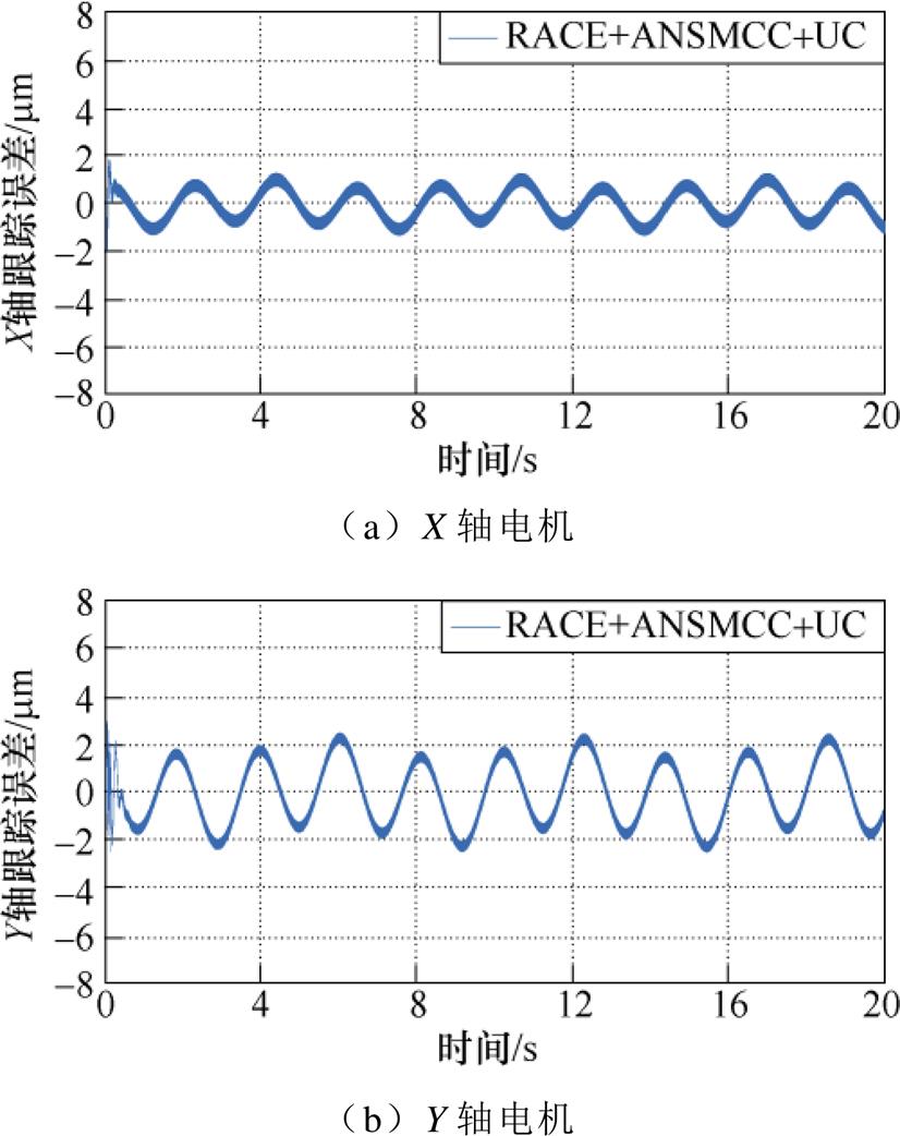
图9 基于C3方法的单轴位置跟踪误差曲线
Fig.9 Single-axis position tracking error curves based on C3 method
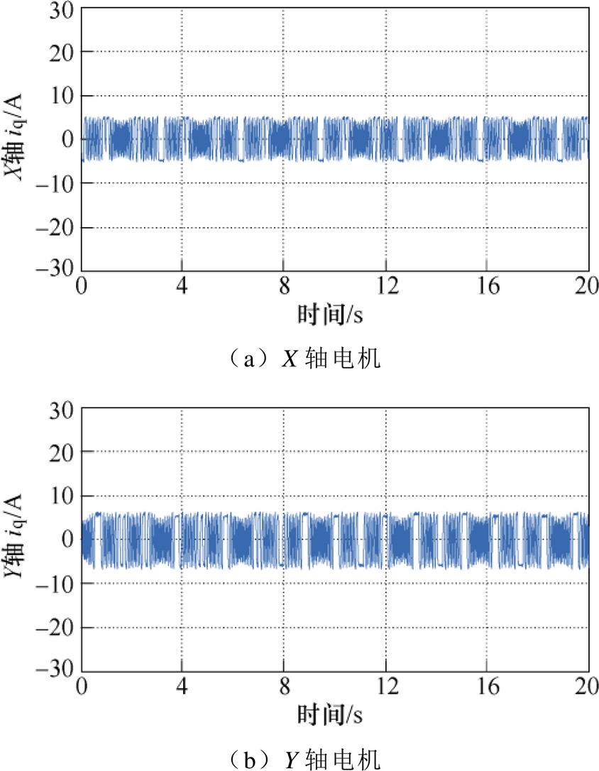
图10 基于C3方法的q轴电流曲线
Fig.10 q-axis current curves based on C3 method
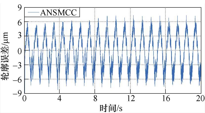
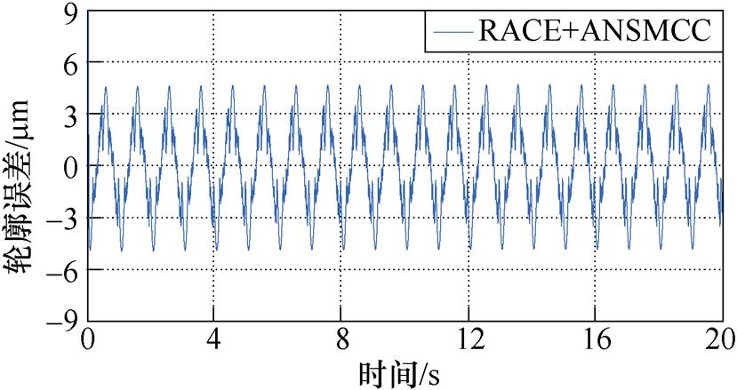
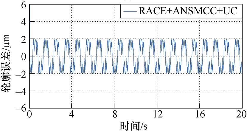
此外,在实验③中,采用C1、C2和C3三种方法控制下的四叶草轮廓跟踪曲线和轮廓误差跟踪曲线分别如图11和图12所示。从图12a和图12b可以看出,采用ASMCC方法的轮廓跟踪误差约为-6.2~6.5 mm,采用基于RACE和ANSMCC方法的轮廓跟踪误差曲线约为-3.9~3.8 mm,相比于ASMCC,将轮廓跟踪精度提升了41.5%。对比图12b和图12c可以看出,在利用UC补偿不确定性后,轮廓误差曲线的波动幅度有所下降,且误差幅值降为-2.7~2.9 mm左右,这表明基于RACE和UC的直驱XY平台ANSMCC方法在负载条件时仍然具有较好的轮廓跟踪性能,UC能够有效补偿不确定性动力学对系统的影响,确保系统准确地跟踪大曲率轮廓曲线,提高直驱XY运动平台的鲁棒性和轮廓跟踪精度。
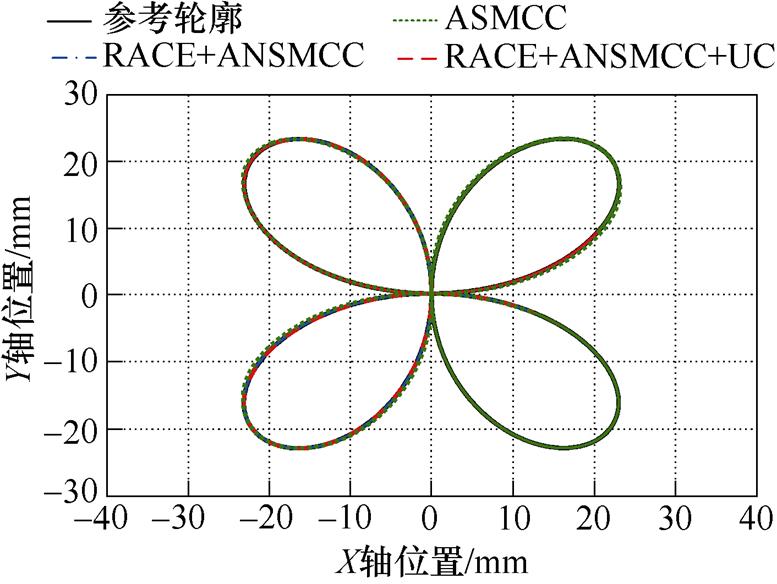
图11 四叶草轮廓跟踪曲线
Fig.11 Contour tracking curves of clover
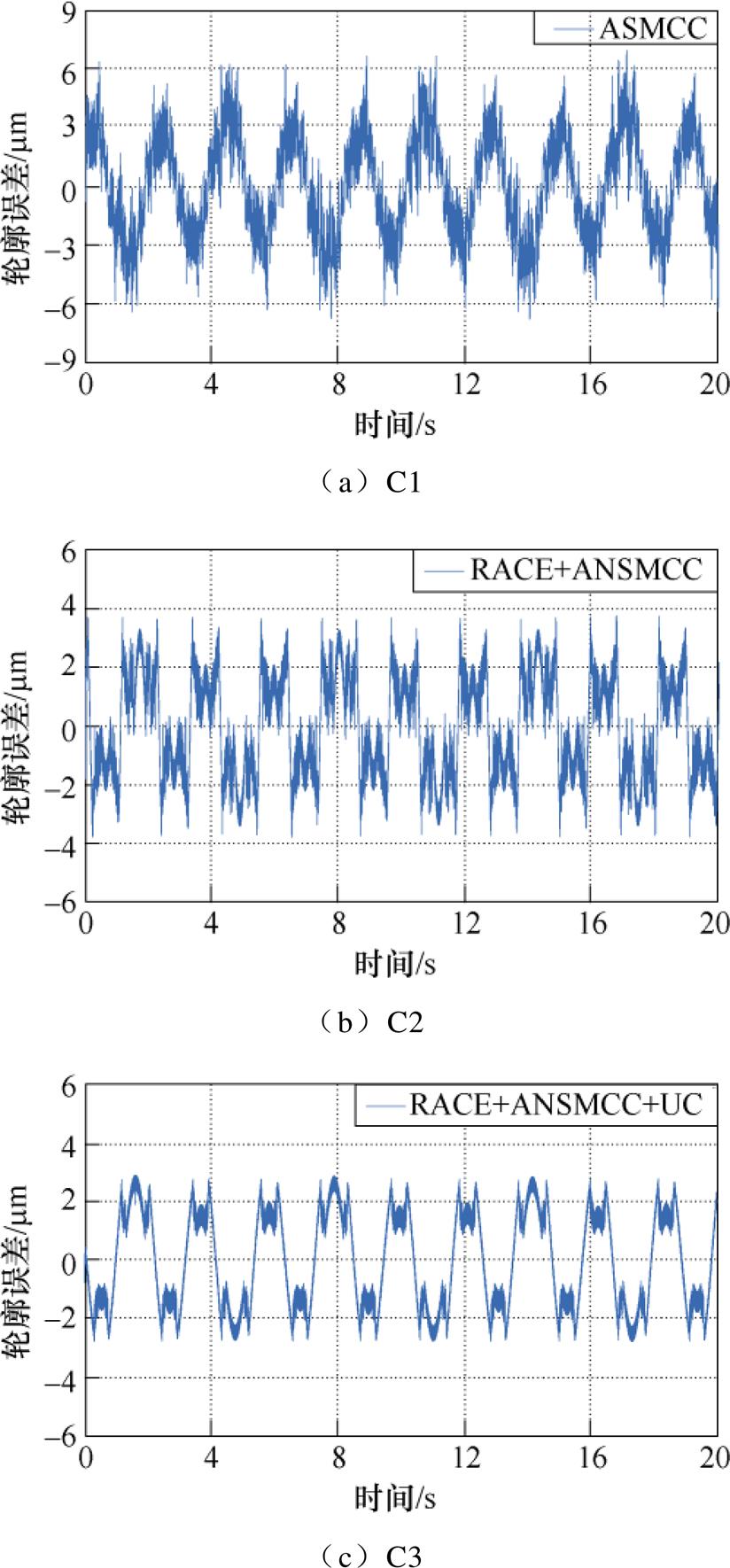
图12 四叶草期望轨迹轮廓跟踪误差曲线
Fig.12 Contour error tracking curves of the clover desired trajectory
为提高直驱XY平台在执行大曲率加工任务时的轮廓加工精度,利用坐标变换和等效轮廓误差思想提出RACE模型,并基于此模型设计具有非线性滑模面的ANSMCC方法,减小轮廓跟踪误差并提高系统动态响应速度。为克服不确定性动力学对系统的影响,设计UC以提高系统的鲁棒性。最后通过实验得出:
1)同传统的以跟踪误差法向分量近似轮廓误差的方法相比,RACE模型更适用于大曲率参考轨迹,具有简单、准确的特点。
2)通过引入非线性滑模面,ANSMCC方法能够有效提高系统响应速度和轮廓加工精度。
3)UC可以补偿不确定性动力学对系统的影响,从而使直驱XY运动平台伺服系统具有较强的鲁 棒性。
参考文献
[1] 李争, 安金峰, 肖宇, 等. 基于自适应观测器的永磁同步直线电机模型预测控制系统设计[J]. 电工技术学报, 2021, 36(6): 1190-1200.
Li Zheng, An Jinfeng, Xiao Yu, et al. Design of model predictive control system for permanent magnet synchronous linear motor based on adaptive observer[J]. Transactions of China Electrotechnical Society, 2021, 36(6): 1190-1200.
[2] 苏光靖, 李红梅, 李争, 等. 永磁同步直线电机无模型电流控制[J]. 电工技术学报, 2021, 36(15): 3182-3190.
Su Guangjing, Li Hongmei, Li Zheng, et al. Research on model-free current control of permanent magnet synchronous linear motor[J]. Transactions of China Electrotechnical Society, 2021, 36(15): 3182-3190.
[3] Deng Jie, Liu Yingxiang, Li Kai, et al. Design, modeling, and experimental evaluation of a compact piezoelectric XY platform for large travel range[J]. IEEE Transactions on Ultrasonics, Ferroelectrics, and Frequency Control, 2020, 67(4): 863-872.
[4] 李争, 肖宇, 孙鹤旭, 等. 基于速度前瞻的双轴直线电机交叉耦合控制策略[J]. 电工技术学报, 2021, 36(5): 973-983.
Li Zheng, Xiao Yu, Sun Hexu, et al. Speed pro- spective based cross-coupling control strategy for dual-axis linear motor[J]. Transactions of China Elec- trotechnical Society, 2021, 36(5): 973-983.
[5] 原浩, 赵希梅, 杜畅. 基于双边界层滑模观测器的双轴直驱平台迭代学习轮廓控制[J]. 电机与控制学报, 2021, 25(4): 81-87.
Yuan Hao, Zhao Ximei, Du Chang. Iterative learning contouring control for dual axis direct drive platform servo system with dual boundary layer sliding mode observer[J]. Electric Machines and Control, 2021, 25(4): 81-87.
[6] 武志涛, 杨永辉. 直线电机驱动XY平台精密轮廓跟踪控制[J]. 中国电机工程学报, 2018, 38(19): 5863-5868, 5944.
Wu Zhitao, Yang Yonghui. Precise contour tracking control for linear motor drive XY tables[J]. Pro- ceedings of the CSEE, 2018, 38(19): 5863-5868, 5944.
[7] Wang Guirong, Gong Xinman, Li Yingqi. Contour error control of X-Y platform based on nominal model in polar coordinate system[J]. Journal of Physics: Conference Series, 2019, 1187(3): 032051.
[8] 武志涛, 杨永辉. 一种永磁直线电机驱动X-Y平台精密轮廓跟踪控制策略[J]. 电工技术学报, 2018, 33(17): 4037-4043.
Wu Zhitao, Yang Yonghui. A precise contour tracking control method for X-Y table driven by permanent magnet linear motors[J]. Transactions of China Elec- trotechnical Society, 2018, 33(17): 4037-4043.
[9] 武志涛, 朱连成. 基于滑模轮廓控制器的直线电机精密运动平台轨迹跟踪控制[J]. 中国电机工程学报, 2015, 35(23): 6188-6193.
Wu Zhitao, Zhu Liancheng. Trajectory tracking control for the motion table driven by linear motors based on sliding mode contour tracking controllers[J]. Proceedings of the CSEE, 2015, 35(23): 6188-6193.
[10] 张康, 王丽梅. 基于融合误差的直驱H型平台自适应全局滑模轮廓控制[J]. 中国电机工程学报, 2020, 40(16): 5337-5345.
Zhang Kang, Wang Limei. Adaptive global sliding mode contour control of direct drive H-type platform based on integrated error[J]. Proceedings of the CSEE, 2020, 40(16): 5337-5345.
[11] 张康, 王丽梅. 基于反馈线性化的永磁直线同步电机自适应动态滑模控制[J]. 电工技术学报, 2021, 36(19): 4016-4024.
Zhang Kang, Wang Limei. Adaptive dynamic sliding mode control of permanent magnet linear syn- chronous motor based on feedback linearization[J]. Transactions of China Electrotechnical Society, 2021, 36(19): 4016-4024.
[12] Liu Yang, Wan Min, Xiao Qunbao, et al. Combined predictive and feedback contour error control with dynamic contour error estimation for industrial five-axis machine tools[J]. IEEE Transactions on Industrial Electronics, 2022, 69(7): 6668-6677.
[13] Li Bo, Wang Taiyong, Wang Peng. Cross-coupled control based on real-time Double Circle contour error estimation for biaxial motion system[J]. Measurement and Control, 2021, 54(3/4): 324-335.
[14] Zhang Yanqing, Yin Zhonggang, Li Wei, et al. Finite control set model predictive torque control using sliding model control for induction motors[J]. CES Transactions on Electrical Machines and Systems, 2021, 5(3): 262-270.
[15] 金鸿雁, 赵希梅, 原浩. 永磁直线同步电机动态边界层全局互补滑模控制[J]. 电工技术学报, 2020, 35(9): 1945-1951.
Jin Hongyan, Zhao Ximei, Yuan Hao. Dynamic boundary layer global complementary sliding mode control for permanent magnet linear synchronous motor[J]. Transactions of China Electrotechnical Society, 2020, 35(9): 1945-1951.
Abstract The direct drive XY motion platform can realize the movement of multi-axis high-end CNC machine tools in the XY coordinate system. It has the advantages of fast response speed and high machining accuracy, which is the key to achieving precise contour control. However, the direct drive XY motion platform uses two permanent magnet linear synchronous motors as the power source. The nonlinear dynamics in the system will directly affect the motion of the platform without attenuating the transmission links. In addition, the matching and coordination of the two feed drive axes in the motion process will also reduce the contour machining accuracy of the system. The precision direct drive XY motion platform is vulnerable to the influence of the system uncertainty dynamics and the dual axis coordination matching when performing the machining tasks. Therefore, an adaptive nonlinear sliding mode contour control (ANSMCC) method is proposed based on the reference adjusted contour error (RACE) model and uncertainty compensator (UC).
Firstly, the dynamic model of the direct drive XY motion platform is established, including uncertainty factors such as parameter variations, external disturbances, and nonlinear friction forces. Next, the traditional method of regarding the normal component of the tracking error as an approximate contour error is not applicable to the large curvature contour machining path. A RACE model is established to calculate a more accurate contour error using coordinate transformation and equivalent contour error theory. Since the direct drive XY platform servo system will be affected by the nonlinear dynamics in the operation process, the ANSMCC method and UC method are designed to control the linear reference model and the nonlinear dynamics. Based on the designed RACE model, an ANSMCC is designed. The nonlinear sliding mode surface is introduced in ANSMCC to replace the traditional linear sliding mode surface, guaranteeing the system has a fast dynamic response speed while enhancing the contour tracking accuracy. Meanwhile, regarding the uncertain dynamics in the system, the UC method and linear sliding mode controller are designed to reduce the error between the reference model and the actual object and compensate for the influence of uncertain dynamics on the contour accuracy. Finally, three comparative experimental conditions, including no-load low-speed condition, no-load high-speed condition, and load condition, are conducted under the three contour control methods of adaptive sliding mode contour control (ASMCC), and ANSMCC based on RACE and UC. In order to ensure the fairness of the comparison experiments, all parameters in the experiment are repeatedly debugged, and appropriate parameters are selected to meet the dynamic and static performance of the system. The proposed ANSMCC based on the RACE and UC methods can decrease the contour error of the direct drive XY motion platform to -2.5~2.5 mm. Compared with the other two methods, contour tracking accuracy is significantly improved, which can meet the contour machining accuracy requirements in practical applications.
The following conclusions can be drawn from the experimental analysis: (1) Compared with the traditional method of approximating the contour error by the normal component of the tracking error, the RACE model is more suitable for the reference trajectory with large curvature, which is simple and accurate; (2) The ANSMCC method can improve system response speed and contour machining accuracy by introducing a nonlinear sliding surface; (3) UC can compensate for the influence of uncertain dynamics on the system. Thus the direct drive XY motion platform servo system has strong robustness.
keywords:Direct drive XY motion platform, reference adjustment contour error, uncertainty compensator, adaptive nonlinear sliding mode contour control, contour machining accuracy
DOI: 10.19595/j.cnki.1000-6753.tces.221447
中图分类号:TM351
辽宁省博士科研启动基金计划资助项目(2022-BS-177)。
收稿日期 2022-07-27
改稿日期 2022-08-23
金鸿雁 女,1993年生,博士,讲师,研究方向为电机控制、智能控制。E-mail: jinhongyanch@163.com(通信作者)
宫艳书 女,1999年生,硕士研究生,研究方向为电机控制。E-mail: 18523916253@163.com
(编辑 崔文静)