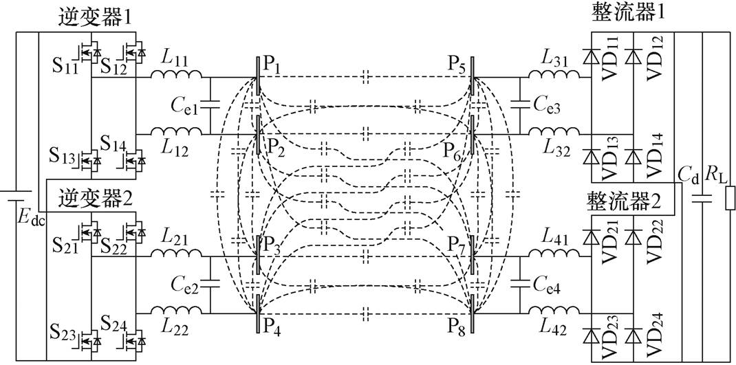
图1 双发射双接收EC-WPT系统电路
Fig.1 Circuit of EC-WPT system with dual transmitter and dual receiverelectric-field coupler
摘要 近年来,随着供电水平要求的提高,单发射单接收的电场耦合无线电能传输(EC-WPT)系统难以满足不同功率等级应用的需求。采用多发射多接收的EC-WPT系统可以有效地扩展输出功率等级。然而,在考虑耦合机构的全电容模型的情况下,因为传能通道间的耦合关系,多发射多接收的EC-WPT系统会存在系统失谐问题。为了解决此问题,该文提出一种基于同侧解耦型耦合机构的双发射双接收的EC-WPT系统。首先,建立一个典型的双发射双接收EC-WPT系统模型,分析同侧耦合对系统谐振的影响效果。然后,提出基于分裂极板的解耦型耦合机构的结构,论证其应用在EC-WPT系统电路中的解耦效果并分析了其解耦原理、耦合系数及偏移性能。最后,搭建了一个功率为200 W的实验样机。实验结果表明,所提出的耦合机构具有较好的同侧解耦特性,基于该耦合机构的EC-WPT系统能在不同工作条件下始终保持谐振状态。
关键词:电场耦合 无线电能传输 双发射双接收 同侧解耦型耦合机构
电场耦合无线电能传输(Electric-field Coupled Wireless Power Transfer, EC-WPT)和磁场耦合无线电能传输(Magnetic-field Coupled Wireless Power Transfer, MC-WPT)作为两种主要的无线电能传输(Wireless Power Transfer, WPT)技术[1],已经引起越来越多的学者关注。EC-WPT系统通过金属极板之间的高频交变电场来传输电能,所采用的电场耦合机构具有设计灵活性高、质量轻和体积小等优 点[2-5]。近年来,在对体积和质量有严格要求的无人机[6]、水下自主机器人[7-9]、电动汽车[10-11]和轨道交通[12]等应用领域中,围绕EC-WPT技术的研究逐渐增多。
随着电气设备类型的增加,不同功率等级的充电要求也随之增加。以电动车为例,电动汽车、电动卡车和电动公共汽车等不同类型车辆所需的充电功率范围覆盖了3.7~22 kW[13]。为了适应不同应用的无线充电功率的要求,需要重复研发适用于WPT系统的不同容量的电能变换装置。可扩展的模块化设计作为一种较优的解决思路,通过将多个具有适当功率容量的WPT模块级/并联,从而构建不同功率级别的WPT系统,用以满足实际用电需求。
然而,现有模块化WPT系统的研究主要集中在MC-WPT技术。在模块化MC-WPT系统中,多个功率通道之间存在同侧耦合作用,这会影响系统的谐振状态,进而导致系统的传输功率和效率的下降[14]。现有消除模块化MC-WPT系统中不利于系统谐振的同侧耦合影响的方法主要分为电路解耦 法[15-17]和磁路解耦法[18-20]。
在电路解耦法中,为了消除同侧耦合,需要在原始系统中添加附加元件或装置,如辅助电容[15]、共享电容[16]或变压器[17]。这些方法利用附加元件或装置的阻抗来抵消耦合线圈之间因交叉耦合而产生的互感,从而实现电路解耦。然而,由于采用了更多的元器件,这些方法在质量和体积上都没有优势。此外,由此衍生出的高阶补偿网络的参数设计问题也使得系统设计变得更加复杂。
在磁路解耦方法中,为了消除同侧耦合,设计了多种带有两个解耦线圈的传能线圈,如双极线 圈[18]、DDQ线圈[19]和四极环线圈[20]等。通过合理设计绕组的形状和相对位置,能够使得两个线圈之间的互感为零。这种方法从根本上解决了线圈之间的交叉耦合,相比于电路解耦法更简单直接。然而,这些现有方法仅适用于MC-WPT系统中耦合线圈的解耦。类似于MC-WPT系统,在具有多发射和/或多接收的电场耦合机构中,各耦合极板之间也存在复杂的耦合电容[21]。文献[22]中表明,多发射多接收EC-WPT系统耦合机构的交叉耦合也会影响系统的运行状态,而该问题尚未得到重视和有效解决。
为了填补已确定的研究空白,本文提出了一种适用于具有多功率传输通道的EC-WPT系统的同侧解耦型电场耦合机构,以解决多端口耦合机构的交叉耦合对系统谐振的影响。以具有双发射双接收耦合机构的EC-WPT系统为例,首先建立了多端口电场耦合机构的全电容电路模型和数学模型,分析了交叉耦合对系统输入阻抗角的影响,发现同侧互电容是系统失谐的主要原因。然后提出了一种基于分裂极板的同侧解耦型电场耦合机构,分析了耦合机构的解耦原理、耦合系数和偏移性能。最后,对所提出的解耦型耦合机构进行了实验验证。
图1为典型的双发射双接收的EC-WPT系统电路。双发射双接收EC-WPT系统的耦合机构由八块金属板P1~P8组成,其构成了一个四端口网络。值得注意的是,本文考虑了八块极板的全电容模型,即任意两块极板之间都考虑了耦合电容。由S11~S14和S21~S24构成的两个逆变器的驱动信号保持一致,因此逆变器产生的高频交流电压相位相同。对于每个耦合通道,使用由两组谐振电感和一个外电容组成的双边LC补偿网络使系统谐振运行。此外,两个整流器并联连接,将交流电压转换为直流电压,为负载供电。
图1 双发射双接收EC-WPT系统电路
Fig.1 Circuit of EC-WPT system with dual transmitter and dual receiverelectric-field coupler
图1中,在考虑耦合机构全电容模型情况下,由八块耦合极板组成的电场式耦合机构共有
 个耦合电容。由所有耦合电容组成的网络可视为四端口网络,如图2所示。端口上的所有电压和电流都标记在图中。
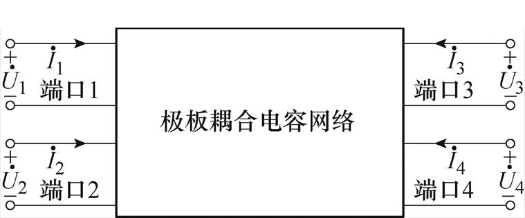
图2 极板耦合电容网络的四端口网络
Fig.2 Four-port network of the coupling capacitance network among plates
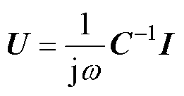
将极板Pi和Pj之间的耦合电容定义为Cij,根据文献[21]中提出的多端口电场耦合机构的一般电容模型,双发射双接收电场耦合机构的端口电压与电流关系可用矩阵方程描述为
 (1)
(1)
其中
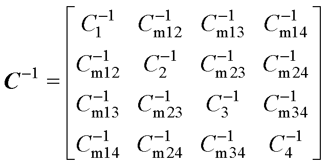

式中,w 为系统角频率。矩阵C中所有元素的计算过程已在文献[21]中详细描述。矩阵中对角线元素Ci定义为端口i的自电容,其他元素Cmij定义为端口i和端口j之间的互电容。将12个互电容定义为三个类别,即:由Cm12、Cm21、Cm34和Cm43组成的同侧互电容;由Cm13、Cm31、Cm24和Cm42组成的正对互电容;由Cm14、Cm41、Cm23和Cm32组成的交叉互电容。值得注意的是,Cmij与Cij具有不同的物理含义,前者是指端口之间的互电容,后者是指极板之间的耦合电容。
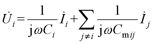
根据式(1),耦合机构端口电压表达式为
 (2)
(2)
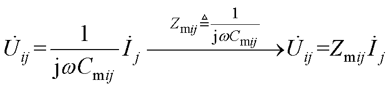
端口i的电压 由两部分组成,第一分量为由端口电流Ii流经自电容Ci上所形成的电压,第二分量是由所有剩余端口上的电流Ij通过互电容Cmij在端口i上所产生的感应电压。端口i上由端口j电流产生的感应电压定义为
 (3)
(3)
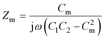
式中,Zmij定义为端口i和j之间的互容阻抗。值得注意的是,在多发射多接收MC-WPT系统中,端口j的电流在端口i上产生的感应电压为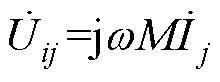 。其中互感M与两个端口之间耦合强弱呈正相关,即互感M越大,耦合越强。但是在式(3)中,EC-WPT系统的感应电压
 与互电容Cmij负相关,这意味着互电容越小,耦合越强。虽然这一规律类似电容越小其阻抗越大的规律,也符合电容与电感的对偶特性,但是为了让描述耦合强弱的参数与耦合强弱正相关,本文采用与感应电压成正比的互容阻抗Zmij来描述端口间的耦合强弱。
基于式(1)~式(3),双发射双接收电场耦合机构的等效电路如图3所示,每个端口为由一个自电容和三个电流控制电压源(Current Controlled Voltage Source, CCVS)组成的独立回路。
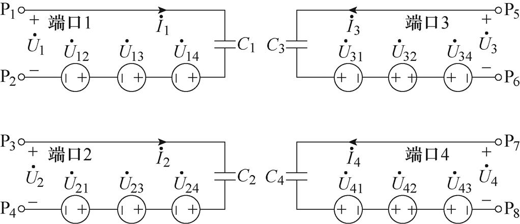
图3 双发射双接收电场耦合机构等效电路
Fig.3 The equivalent circuitof dual-transmitter and dual-receiverelectric-field coupler
结合图3中电场耦合机构的等效电路,图1中双发射双接收EC-WPT系统的等效电路如图4所示。基于基波近似法,EC-WPT系统中的全桥逆变器可以等效为交流电压源,而整流电路和直流负载可以等效为两个交流负载电阻。与传统的单发射单接收双边LC的EC-WPT系统类似,电感用于补偿耦合机构的自电容,即:图1中的补偿电感和图4中的补偿电感L1、L2、L3和L4满足
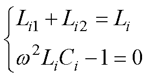 (4)
(4)
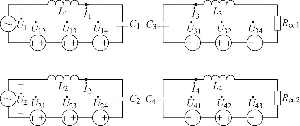
图4 双发射双接收EC-WPT系统等效电路
Fig.4 Equivalent circuit of the dual-transmitter and dual-receiver EC-WPT system
式中,由基尔霍夫电压定律(Kirchhoff’s Voltage Law, KVL)可知,当补偿电感与自电容满足谐振关系时,图5中的等效电路可以用方程表示为
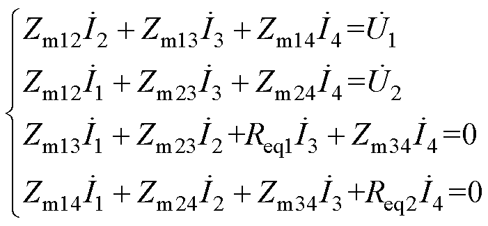 (5)
(5)
原边电流可从式(5)中计算得到
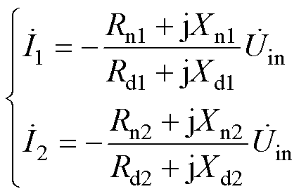 (6)
(6)
式(6)的表达式为分数,其分母和分子均由实部(Rn1, Rd1, Rn2, Rd2)和虚部(Xn1, Xd1, Xn2, Xd2)组成。其中,虚部表示为
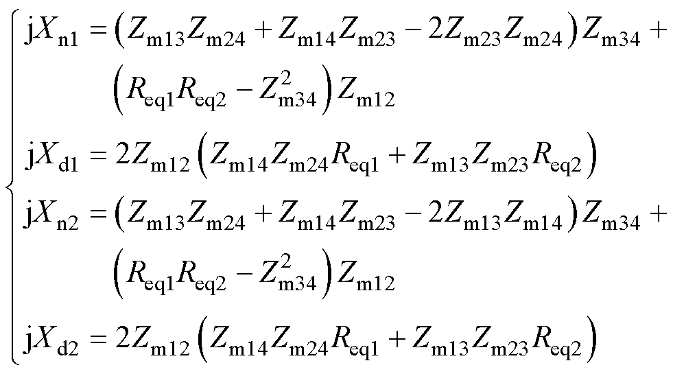 (7)
(7)
从式(6)和式(7)中可知,当同侧互容阻抗Zm12和Zm34都为0时,仅通过补偿耦合机构的自电容,就能满足逆变器的输出电压 与电流
与电流 和
和 相位保持一致。由于Zm12代表端口1和端口2的互容阻抗,Zm34代表端口3和端口4的互容阻抗,这意味着,当耦合机构同一侧的两个端口解耦时,EC-WPT系统能够谐振运行。否则,系统的输入阻抗角不是0,且系统运行状态会受等效负载Req1和Req2的影响。
以一个具有传统双发射双接收电场耦合机构的运行频率为800 kHz的EC-WPT系统为例,研究系统两通道输入阻抗角与负载电阻的关系。图5给出了具有八块金属板P1~P8的传统双发射双接收电场耦合机构的结构。其尺寸为:lg1=250 mm,lg2= 500 mm,dg1=10 mm,dg2=10 mm,同时设定耦合机构的四个外电容值为200 pF。基于Ansys Maxwell有限元仿真得出的电容矩阵数据和文献[21]中的建模方法,可以计算得到耦合机构所有的自电容和互电容。耦合机构等效电路的主要参数见表1,此时耦合机构的同侧互容阻抗Zm12和Zm34约为6.8 W。值得注意的是,需要将与耦合机构并联的外部电容视为耦合机构的一部分,并在建模过程中加以考虑。
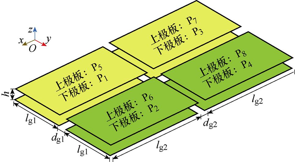
图5 传统双发射双接收电场耦合机构的八极板结构
Fig.5 Structure of a typicaldual-transmitter and dual-receiverelectric-field coupler with eight plates
表1 传统耦合机构的主要参数
Tab.1 Main parameters of the typical electric-field coupler

参 数数 值 C1/pF236.59 C3/pF236.56 Zm12/W6.74 Zm14/W2.90 Zm24/W102.47 C2/pF236.62 C4/pF236.51 Zm13/W102.54 Zm23/W2.90 Zm34/W6.80
将图5中的耦合机构连接到图1的系统电路中,并根据式(4)通过谐振电感补偿自电容,系统输入阻抗角a 与b 的关系曲线如图6所示。由于耦合机构为对称结构,输入阻抗角几乎相等。此外,当且仅当负载电阻为65 W 时,输入阻抗角a 和b 都为0。在大多数负载条件下,系统输入阻抗呈容性,而这不利于逆变器开关管工作在零电压开通状态。
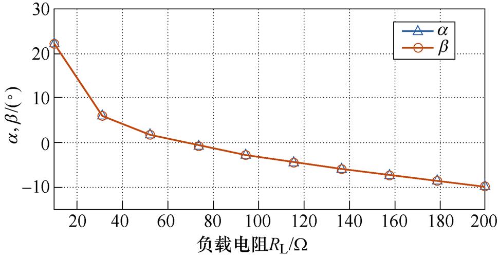
图6 输入阻抗角a 与b 和RL的关系(传统耦合机构)
Fig.6 Relationship between input impedance angles a and b against load RL (Typical coupler)
基于分裂极板的解耦型十六极板(双发射双接收)电场耦合机构如图7所示。耦合机构包括多发射极板结构和多接收极板结构,其中多发射极板结构包括4×2阵列式排布的8块子发射极板p1~p8,多接收极板结构包括4×2阵列式排布的8块子接收极板p9~p16,共计16块耦合极板。子发射极板p1、p2连接作为发射极板P1,子发射极板p3、p4连接作为发射极板P2,子发射极板p6、p7连接作为发射极板P3,子发射极板p5、p8连接作为发射极板P4;子接收极板p9、p10连接作为接收极板P5,子接收极板p11、p12连接作为接收极板P6,子接收极板p14、p15连接作为接收极板P7,子接收极板p13、p16连接作为接收极板P8。可见在所提出的耦合机构中,耦合极板成对连接。因此,从耦合机构的等效电路角度来看,所提出的十六耦合机构仍为八极板,对应于图5中传统耦合机构的P1~P8。
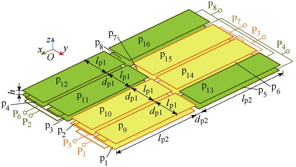
图7 基于分裂十六极板的同侧解耦型电场耦合机构
Fig.7 Structure of the proposed separate-plates based decoupled electric-field coupler with sixteen plates
为了对比前后两种耦合机构的特性,设定基于分裂极板的耦合机构的几何尺寸与图5中的耦合机构相同。尺寸为:lp1=120 mm,lp2=500 mm,dp1= 10 mm,dp2=10 mm,h=20 mm,设定耦合机构的四个外电容值为200 pF。同样地,基于Ansys Maxwell有限元仿真得到电容矩阵和文献[20]中提出的建模方法,计算得到所提出耦合机构等效电路的主要参数,见表2。
表2 新型耦合机构的主要参数
Tab.2 Main parameters of the proposed electric-field coupler
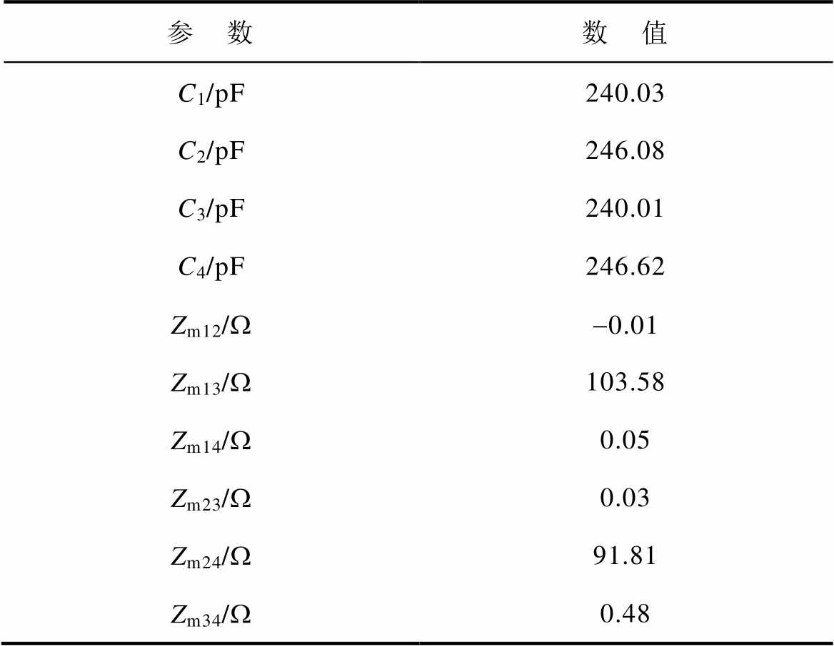
参 数数 值 C1/pF240.03 C2/pF246.08 C3/pF240.01 C4/pF246.62 Zm12/W-0.01 Zm13/W103.58 Zm14/W0.05 Zm23/W0.03 Zm24/W91.81 Zm34/W0.48
结果表明,所提出耦合机构的同侧互容阻抗ZCm12和ZCm34值远小于传统的八极板耦合机构的值,且接近于零。因此,由第1节的推导可知,采用所提出的同侧解耦型耦合机构的EC-WPT系统的逆变器开关能够运行在零电压开通状态。
由于双发射双接收电场耦合机构共有八块耦合极板,极板间的耦合电容电路复杂,不便于清楚地说明所提出耦合机构的解耦原理。因此本节以简单且研究较为成熟的四极板构成的二端口网络为例来说明解耦原理。四极板耦合机构的耦合电容网络如图8a所示,其等效电路如图8b所示。
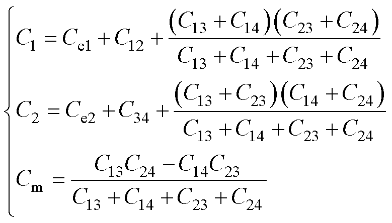
与双发射双接收耦合机构等效电路类似,四极板耦合机构的等效电路也是由自电容与CCVS构成的。两个端口之间的耦合强度由互容抗Zm来表示。在图8b中,耦合机构的互容抗表示为
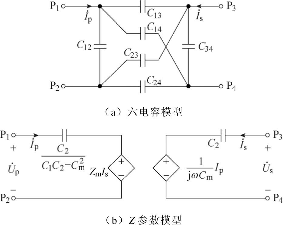
图8 四极板耦合机构
Fig.8 Electric-field coupler with four plates
 (8)
(8)
其中
 (9)
(9)
式中,Ce1和Ce2分别为两个端口的外接电容。当Zm为0 W 时,原边电流通过互容抗在副边感应出的电压也为0 V,此时两个端口互不影响,即可以理解为两个端口是解耦的。
从图7中所提出的耦合机构中选择P1~P4构成一个四极板耦合机构如图9所示,其等效电路构成了一个二端口网络,即端口1与端口2。由于耦合机构是上下对称的,极板P3与极板P1和P2的相对位置和距离是相同的,极板P4与极板P1和P2的相对位置和距离也是相同的,因此极板间的电容满足等式
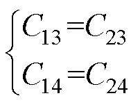 (10)
(10)
式中,Cij为图9中Pi和Pj之间的电容。
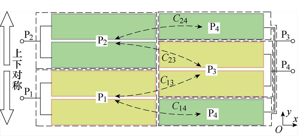
图9 解耦极板P1~P4示意图
Fig.9 Schematic diagram of the decoupled plates P1~P4
将式(10)代入式(8)和式(9),可以得出Zm为0 W,即端口1与端口2是解耦的。此外,依照该解耦原理,只要耦合机构的上下对称性不被改变,那么耦合机构的解耦特性是不变的。换句话说,在图7中只要由极板P3和极板P4构成端口2相对于由极板P1和极板P2构成的端口1在y方向上不发生非对称性偏移,那么端口1与端口2始终是解耦的。而所提出的耦合机构的同侧端口之间都满足上述的对称性,因此可以实现耦合机构同侧端口的解耦。同时,当接收端沿x轴发生偏移或沿z轴发生耦合间距变化时,该耦合机构依然具有解耦特性。
通过将所提出的同侧解耦型分裂极板耦合机构连接到图1所示的电路,建立一个新的EC-WPT系统,其中补偿网络满足式(4)。基于Ansys Maxwell有限元仿真得到电容矩阵和文献[21]中提出的建模方法,图10所示的系统输入阻抗几乎为零。与具有传统耦合机构的系统相比,解决了因交叉耦合而引起的系统失谐问题。
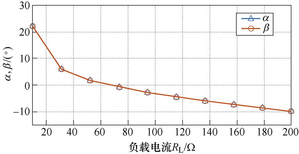
图10 输入阻抗角a 与b 和RL的关系(新型耦合机构)
Fig.10 Relationship curves between input impedance angles a and b against load RL (proposed coupler)
对于EC-WPT系统,耦合机构的耦合系数是反映系统功率传递能力的重要指标。为了简化分析,只考虑了耦合机构的主要耦合通道。耦合机构的耦合系数k与耦合间距h的关系曲线如图11所示。在图11中,k1表示由P1、P2、P5和P6组成通道的耦合系数,k2表示由P3、P4、P7和P8组成通道的耦合系数。式(11)中给出了k1和k2的表达式,其中Z定义为自电容和互电容的阻抗。图11显示了解耦型耦合机构的k1和传统耦合机构的k1与k2是相同的,而所提出耦合机构的k2稍小。这意味着,所提出的耦合机构牺牲了一定的耦合系数来换取解耦特性,然而,随着外部电容的增加,这种耦合系数的差异将变小,这意味着所提出的耦合机构的耦合系数几乎与传统耦合机构相同。
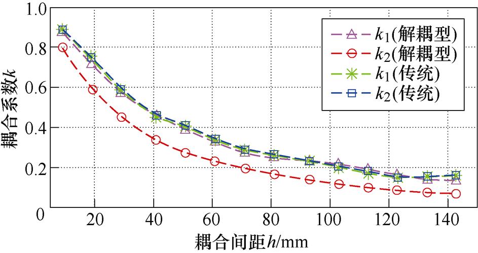
图11 耦合机构的耦合系数k与耦合间距h的关系曲线
Fig.11 Relationship curves between the coupling coefficient k of the coupler against coupling distance h
 (11)
(11)
在轨道交通无线供电应用领域中,如果图7耦合机构的x方向与车辆的行驶方向保持一致,则需要考虑当耦合机构在x方向上发生偏移时其是否仍具有解耦特性。在图12中,所提出的耦合机构的同侧互阻抗Zm12和Zm34始终保持为零,这表明即使当电场耦合机构沿x方向偏移时,同一侧的两对耦合板总是解耦。这是因为在x方向偏移时,2.2节中解释的耦合机构的对称性仍然保持不变。然而,传统的八极板耦合机构的Zm12和Zm34始终大于5 W,这将导致系统失谐。
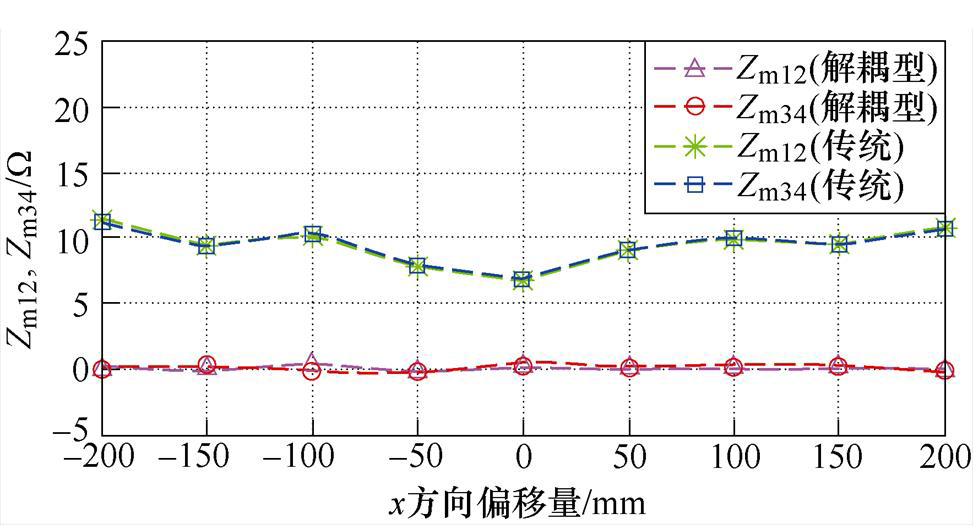
图12 同侧互容阻抗Zm12和Zm34与x方向偏移量的关系曲线
Fig.12 Relationship curves between same-sided mutualimpedance Zm12 and Zm34 against x-misalignment
类似地,耦合机构原、副边极板的耦合间距h对耦合参数也会产生影响。图13给出了所提出的同侧解耦型耦合机构同侧互容阻抗Zm12、Zm34和正对互容阻抗Zm13、Zm24关于耦合间距h的关系曲线。图中主要呈现出两个规律:①正对互容阻抗Zm13和Zm24随着耦合间距的增加而减小,由于这两个互容阻抗主要决定系统的电能传输能力,因此该规律说明了耦合间距越小,系统的电能传输能力越强,这与一般认知一致。②同侧互容阻抗Zm12和Zm34始终保持在零附近,即说明了耦合间距基本不影响所提出的耦合机构同侧端口之间的解耦特性。
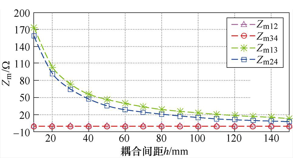
图13 互容阻抗Zm12, Zm34, Zm13, Zm24与耦合间距h的关系曲线
Fig.13 Curves of mutual impedance Zm12, Zm34, Zm13, Zm24 against the coupling distance h
图14所示为搭建的基于同侧解耦型耦合机构的EC-WPT系统实验装置。逆变器和整流器分别采用了SiC MOSFET和快速恢复二极管。根据第2节的结构和尺寸,制作并连接了16块铝板。为了减小趋肤效应,采用绕制在硅铁环形铁心上的0.05 mm的高频利兹线补偿电感,外部电容器Ce1~Ce4由高压陶瓷电容器构成。主要系统参数见表1和表3。
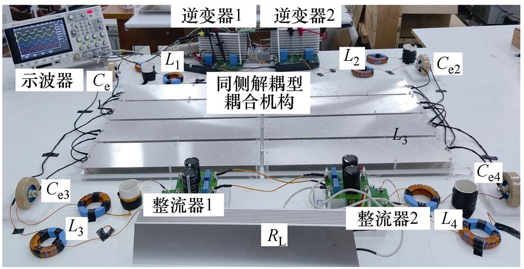
图14 基于解耦型耦合机构EC-WPT系统实验装置
Fig.14 The experiment prototype of the EC-WPT system with the same-sided decoupledelectric-field coupler
表3 实验装置主要参数
Tab.3 Main parameters of the experimental prototype (单位: mH)

参 数数 值 L1164.89 L2160.84 L3164.91 L4160.49
为了验证所提出耦合机构的同侧解耦特性,进行了测试实验,解耦效果实验电路如图15所示。在图15a中,端口1串联补偿电感并工作于谐振状态,即激励电压u1和电流i1同相,其他三个端口均处于断开状态。根据式(2),uoc2的相量形式可表示为
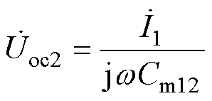 (12)
(12)
式中,uoc2与互容阻抗1/(jwCm12)成比例,可以作为端口1和端口2解耦的标志量。采用相同的原理以uoc4为标志量来验证端口3和端口4的解耦效果,如图15b所示。
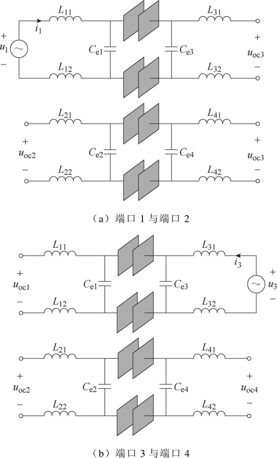
图15 解耦效果实验电路
Fig.15 Same-sided decoupled effect experimental
值得注意的是,虽然图15显示的电路在理想条件下为短路,但是在实际电路中,由于激励电压u1和u3幅值较低,且电感L11、L12和外电容Ce1以及耦合机构存在不可忽略的内阻,故环路电流并非理想短路情况下的无穷大,而是可以接受的有限值。并且,该实验电路的短路工作状态仅用于短时间解耦测试,并非系统的正常工作状态,因此是可以接受的。
图16为当耦合机构正对情况下,解耦型耦合机构解耦效果的检测电路实验波形。在图16a中,uoc2的值约为0 V,这证明了同侧互阻抗Zm12为0 W,同时说明了所提出的耦合机构的端口1和端口2解耦效果良好。图16b中的实验波形说明了所提出耦合机构的端口3和端口4解耦效果也较为良好。
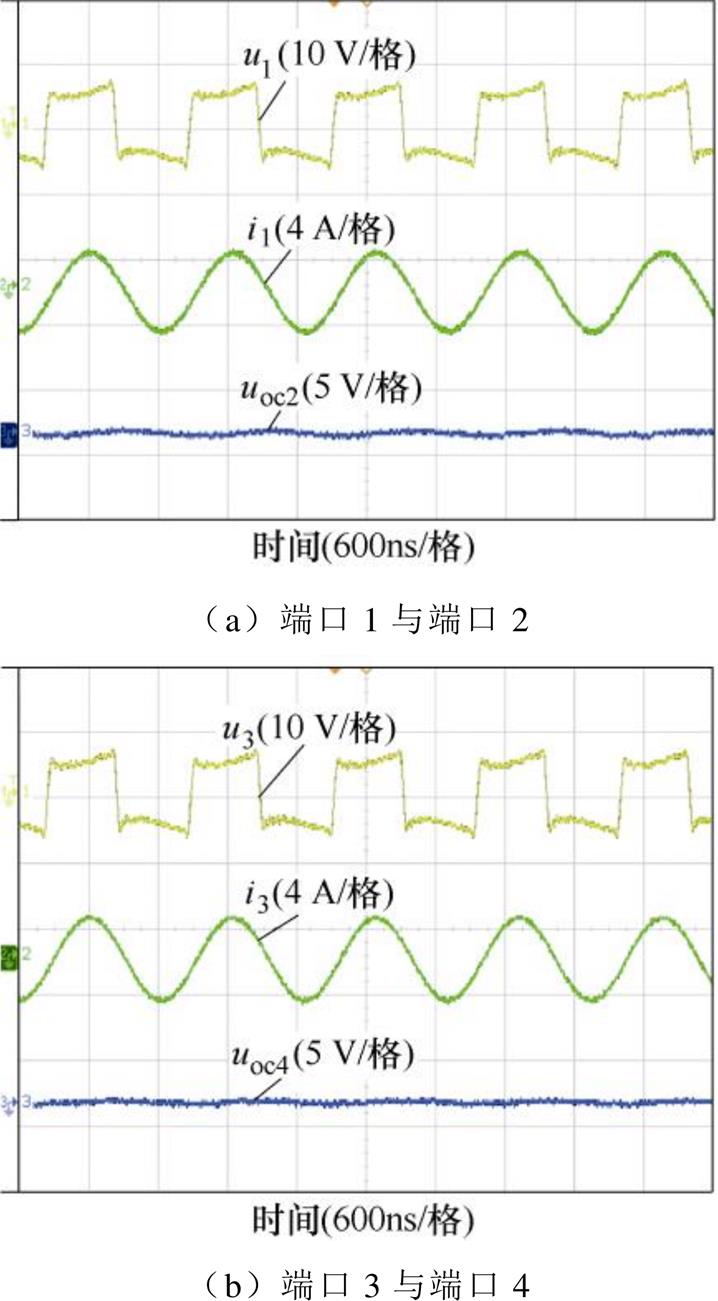
图16 正对情况下解耦效果检测波形
Fig.16 Experimental waveforms of same-sided decoupled effect experimental circuit without misalignment
图17显示了所提耦合机构在x轴偏移情况下(偏移量为100 mm),解耦效果检测电路的实验波形。结果表明,解耦型耦合机构在极板偏移的情况下仍然具有解耦特性。
图18a所示为当两个逆变器的直流输入电压为90 V、负载电阻RL为200 W 时,采用同侧解耦型耦合机构的EC-WPT系统的两个逆变器交流输出电压、电流波形以及输出直流电压的波形。结果显示电压u1、u2和电流i1、i2几乎同相(弱感性)。
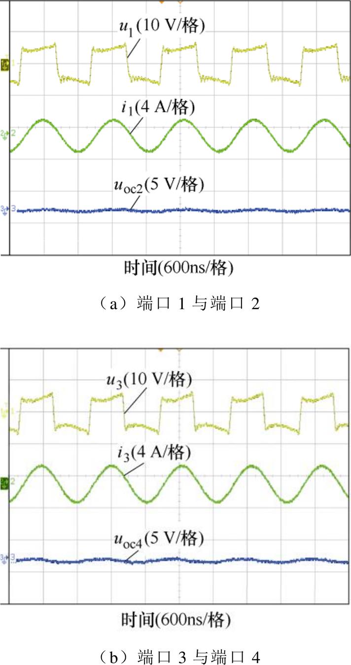
图17 偏移(100 mm)情况下解耦效果检测波形
Fig.17 Experimental waveforms of same-sided decoupled effect experimental circuit with x-axis misalignment (100 mm)
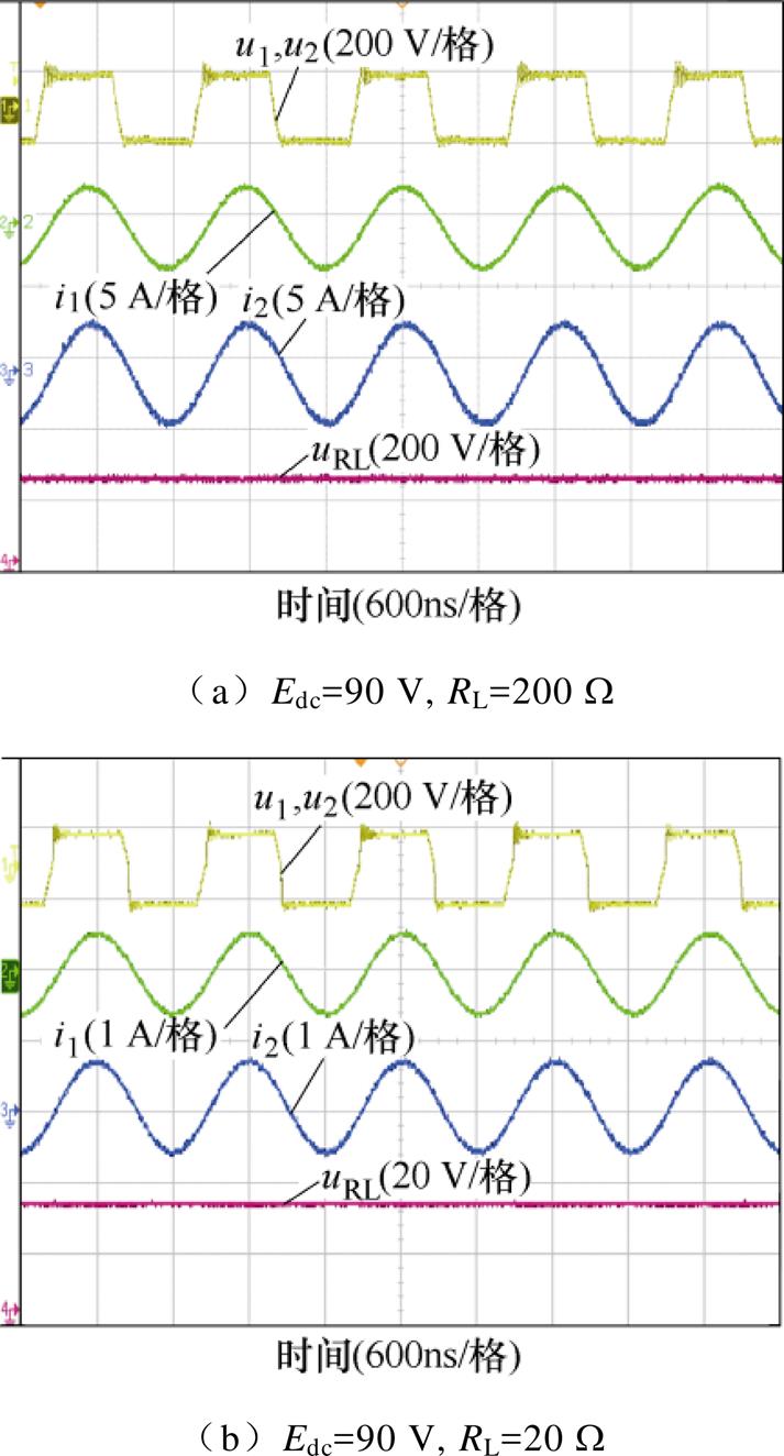
图18 基于解耦型耦合机构的EC-WPT系统实验波形
Fig.18 The waveforms of the EC-WPT system with the same-sided decoupled coupler
图18b给出了当两个逆变器的直流输入电压为90 V,负载电阻RL为20 W 时,采用同侧解耦型耦合机构的EC-WPT系统的两逆变器输出交流电压、电流和负载直流电压的波形。结果显示,电压u1、u2和电流i1、i2仍处于同相位(弱感性),结合图18a的结果,证明了图10所示关系曲线的正确性。
图19给出了负载RL为200 W 和20 W 时EC- WPT系统输出功率Pout和效率h 关于x方向偏移量的关系曲线。图19a中RL为200 W,当x方向偏移量为0时,系统效率达到73 %,随着x方向偏移量的增大,系统效率逐渐下降,这是系统失谐所导致,且支路电流的增加也使得损耗增大。需要注意的是,此处负载RL=200 W 时的最大效率73 %并非系统全负载范围内的最优效率,系统变负载情况下的效率曲线将在3.4节中给出(最优效率83 %)。输出功率方面,随着偏移量的增大,系统输出功率呈现先增大再减小的趋势,这主要是由于系统自容、互容共同变化所导致的系统增益变化,相同的现象还出现在基于LCLC-CL拓扑的系统中[23]。图19b中RL为20 W,x方向偏移量在0时,系统达到最大效率76 %。输出功率方面,随着偏移量的增大,系统输出功率逐渐增大,但随着偏移距离的进一步增加,显然输出功率也会如图19a一致呈现逐渐降低的趋势。
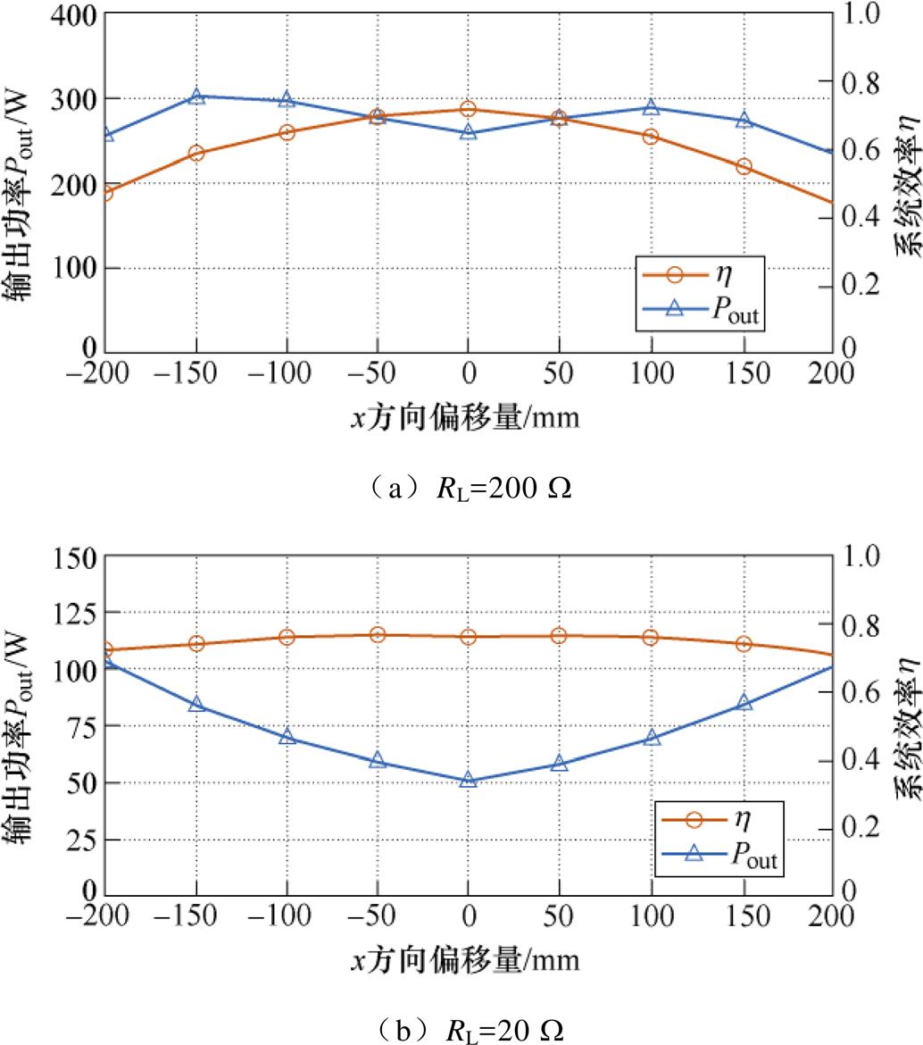
图19 输出功率和效率关于x方向偏移量的关系曲线
Fig.19 Relationship curves between output power and efficiency against x-misalignment
此外,本文还进行了对比实验,在耦合机构相同尺寸情况下,搭建了具有传统双发射双接收电场耦合机构的EC-WPT系统。类似地,基于图15的测试实验电路,完成了传统耦合机构的耦合效果的测试,实验结果如图20所示。结果显示,uoc2与uoc4幅值较大,证明了耦合机构同侧端口之间存在较大的同侧耦合。
图21给出了EC-WPT系统输入阻抗角与负载电阻的关系曲线理论值与实测值。系统的输入阻抗角随负载电阻的变化在较大范围内变化,实验数据的变化趋势与理论分析数据几乎一致。
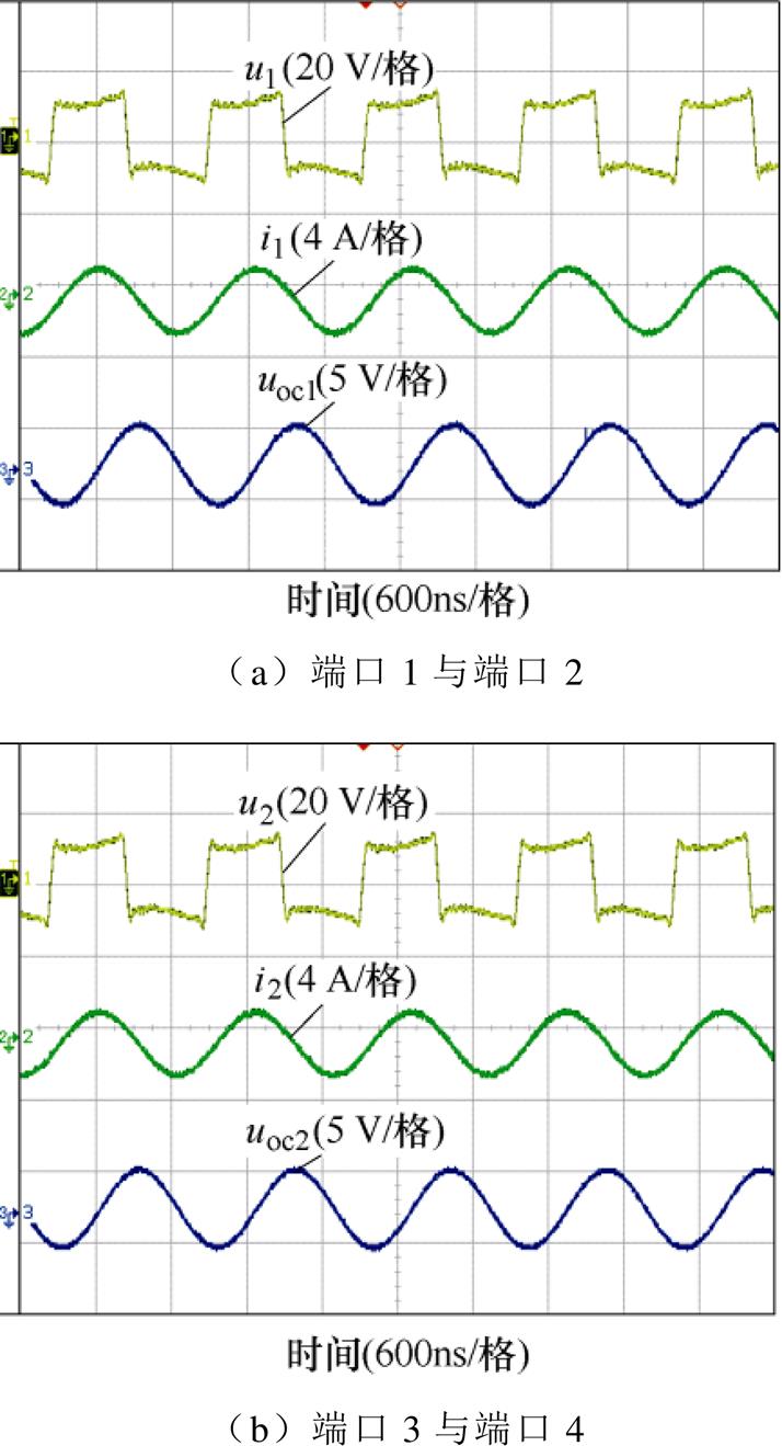
图20 传统耦合机构解耦效果检测波形
Fig.20 Experimental waveforms of typical coupler with same-sided cross-coupling
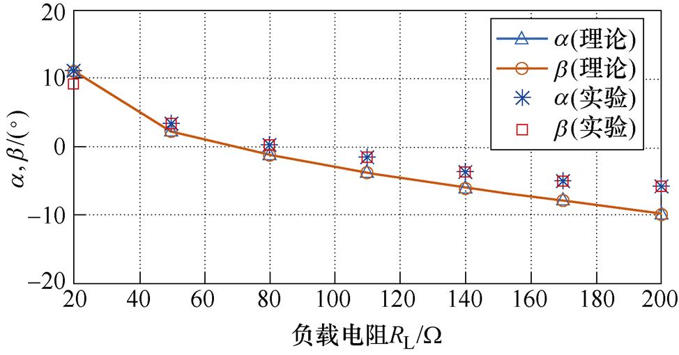
图21 EC-WPT系统输入阻抗角与负载电阻的关系
Fig.21 Curves of input impedance angles of the EC-WPT system against different load resistances
为了证明所提系统在效率和功率提升的优势,将基于同侧解耦型耦合机构的以及基于传统型耦合机构的双发射双接收的EC-WPT系统进行对比实验。输出功率方面,如图22a所示,在相同直流输入电压情况和较宽负载电阻条件下,基于解耦型耦合机构的EC-WPT系统的输出功率始终比基于传统型耦合机构的EC-WPT系统的输出功率高。系统效率方面,如图22b所示,在确保系统输出功率相同的基本前提下,基于解耦型耦合机构的EC-WPT系统的系统效率始终不低于基于传统型耦合机构的EC-WPT系统的效率,且最高效率出现在电阻RL= 80 W 附近,最优系统效率约为83 %。
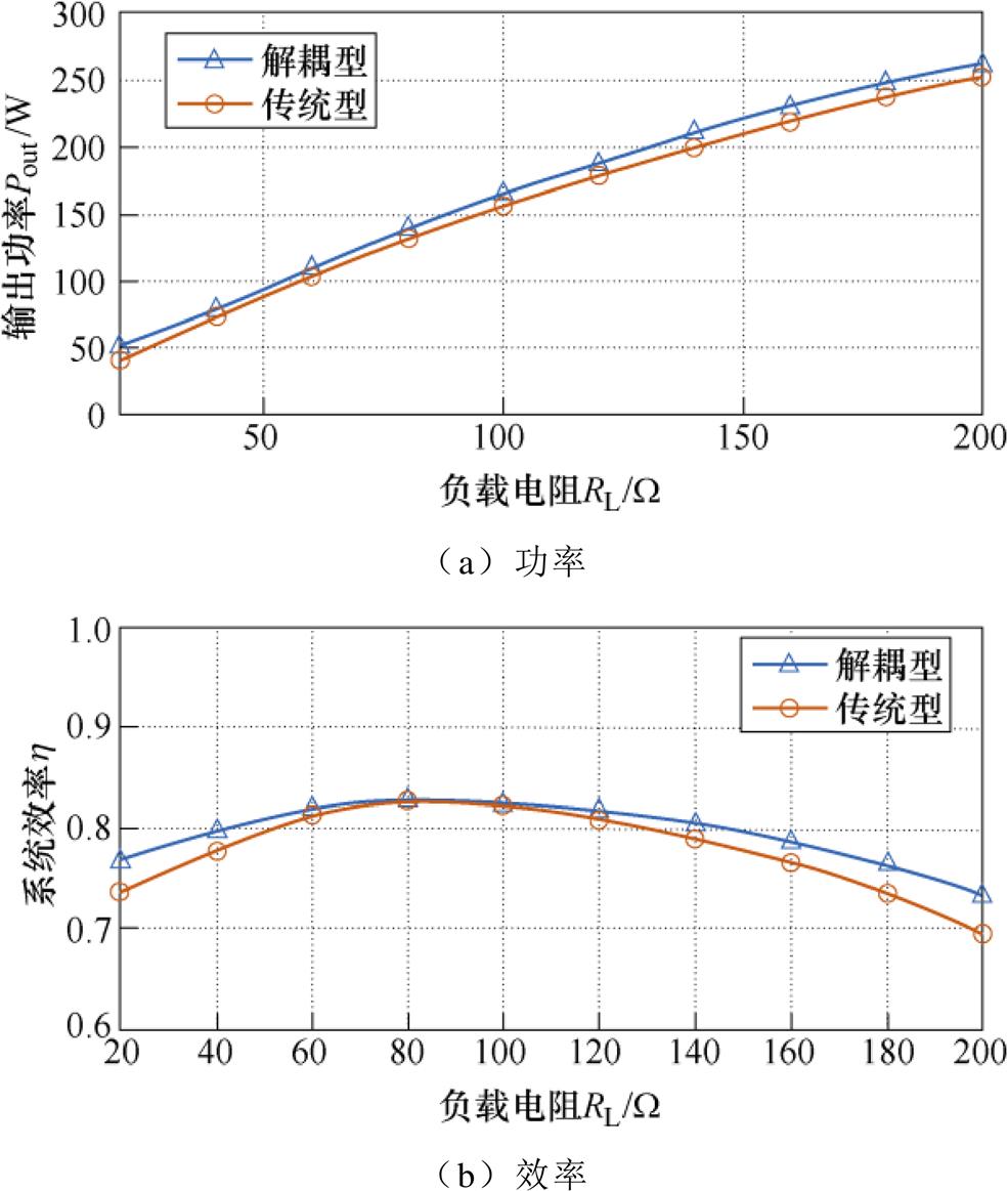
图22 输出功率与效率关于负载电阻的关系曲线
Fig.22 Relationship curves between output power and efficiency against the load resistance
本文提出了一种适用于具有多功率传输通道的EC-WPT系统的同侧解耦型电场耦合机构,该耦合机构从原理上消除了同侧耦合以及解决了由此产生的系统失谐问题。具体给出了基于十六块分裂极板的解耦型耦合机构的结构,并将其应用于EC-WPT系统。理论分析表明,该耦合机构的主耦合系数与传统耦合机构的主耦合系数基本相同,并且在x轴偏移情况下仍能保持解耦效果。当负载在较大范围内变化时,基于解耦型耦合机构的EC-WPT系统能够始终运行在谐振状态,实验结果验证了上述理论分析。
参考文献
[1] 卿晓东, 苏玉刚. 电场耦合无线电能传输技术综述[J]. 电工技术学报, 2021, 36(17): 3649-3663.
Qing Xiaodong, Su Yugang. An overview of electric- filed coupling wireless power transfer technology[J]. Transactions of China Electrotechnical Society, 2021, 36(17): 3649-3663.
[2] 廖志娟, 周磊, 吴镇, 等. 变结构LC-CLCL拓扑恒压恒流型电场耦合电能传输系统[J]. 中国电机工程学报, 2021, 41(17): 6039-6049, 中插23.
Liao Zhijuan, Zhou Lei, Wu Zhen, et al. An electric- field coupled power transfer system with constant voltage and constant current output based on changeable LC-CLCL resonant circuit[J]. Proceedings of the CSEE, 2021, 41(17): 6039-6049, 中插23.
[3] 谢诗云, 刁勤晴, 杨奕, 等. 基于复合谐振网络的恒定输出型ECPT系统[J]. 中国电机工程学报, 2020, 40(24): 8165-8178, 中插33.
Xie Shiyun, Diao Qinqing, Yang Yi, et al. Electric- field coupled power transfer system based composite resonant networks with constant output[J]. Pro- ceedings of the CSEE, 2020, 40(24): 8165-8178, 中插33.
[4] Wang Shiying, Liang Junrui, Fu Minfan. Analysis and design of capacitive power transfer systems based on induced voltage source model[J]. IEEE Transactions on Power Electronics, 2020, 35(10): 10532-10541.
[5] 赵鱼名, 王智慧, 苏玉刚, 等. 基于T型CLC谐振网络的恒压型电场耦合电能传输系统负载自适应技术[J]. 电工技术学报, 2020, 35(1): 106-114.
Zhao Yuming, Wang Zhihui, Su Yugang, et al. Load adaptive technology of constant voltage electric-field coupled power transfer system based on T-CLC resonant network[J]. Transactions of China Electro- technical Society, 2020, 35(1): 106-114.
[6] Park C, Park J, Shin Y, et al. Separated circular capa- citive coupler for reducing cross-coupling capacitance in drone wireless power transfer system[J]. IEEE Transactions on Microwave Theory and Techniques, 2020, 68(9): 3978-3985.
[7] 苏玉刚, 钱林俊, 刘哲, 等. 水下具有旋转耦合机构的电场耦合无线电能传输系统及参数优化方法[J]. 电工技术学报, 2022, 37(10): 2399-2410.
Su Yugang, Qian Linjun, Liu Zhe, et al. Underwater electric-filed coupled wireless power transfer system with rotary coupler and parameter optimization method[J]. Transactions of China Electrotechnical Society, 2022, 37(10): 2399-2410.
[8] Yang Lei, Ju Minna, Zhang Ben. Bidirectional undersea capacitive wireless power transfer system[J]. IEEE Access, 2019, 7: 121046-121054.
[9] Yang Lei, Zhang Yuanqi, Li Xiaojie, et al. Analysis and design of four-plate capacitive wireless power transfer system for undersea applications[J]. CES Transactions on Electrical Machines and Systems, 2021, 5(3): 202-211.
[10] 郭历谋, 罗博, 麦瑞坤. 基于电场耦合式的电动汽车无线充电技术电压优化方法[J]. 电工技术学报, 2020, 35(增刊1): 19-27.
Guo Limou, Luo Bo, Mai Ruikun. Voltage opti- mization method for wireless charging of electric vehicles based on capacitive power transfer[J]. Transactions of China Electrotechnical Society, 2020, 35(S1): 19-27.
[11] Lu Fei, Zhang Hua, Mi C. A two-plate capacitive wireless power transfer system for electric vehicle charging applications[J]. IEEE Transactions on Power Electronics, 2018, 33(2): 964-969.
[12] Liang Jianying, Wu Donghua, Yu Jin. A design method of compensation circuit for high-power dynamic capacitive power transfer system considering coupler voltage distribution for railway applica- tions[J]. Electronics, 2021, 10(2): 153.
[13] (R) Wireless Power Transfer for Light-Duty Plug- in/Electric Vehicles and Alignment Methodology: SAE J2954[S]. SAE, 2020.
[14] Li Yong, Mai Ruikun, Lu Liwen, et al. Analysis and transmitter currents decomposition based control for multiple overlapped transmitters based WPT systems considering cross couplings[J]. IEEE Transactions on Power Electronics, 2018, 33(2): 1829-1842.
[15] Li Yong, Mai Ruikun, Ma Linsen, et al. Dual parallel wound primary coils based IPT systems and its power allocation technique[J]. Proceedings of the CSEE, 2015, 35(17): 4454-4460.
[16] Mai Ruikun, Luo Ying, Yang Bin, et al. Decoupling circuit for automated guided vehicles IPT charging systems with dual receivers[J]. IEEE Transactions on Power Electronics, 2020, 35(7): 6652-6657.
[17] Li Yong, Mai Ruikun, Lin Tianren, et al. A novel WPT system based on dual transmitters and dual receivers for high power applications: analysis, design and implementation[J]. Energies, 2017, 10(2): 174.
[18] Pries J, Galigekere V P N, Onar O C, et al. A 50-kW three-phase wireless power transfer system using bipolar windings and series resonant networks for rotating magnetic fields[J]. IEEE Transactions on Power Electronics, 2020, 35(5): 4500-4517.
[19] Budhia M, Boys J T, Covic G A, et al. Development of a single-sided flux magnetic coupler for electric vehicle IPT charging systems[J]. IEEE Transactions on Industrial Electronics, 2013, 60(1): 318-328.
[20] Zhou Wei, Zhu Zhehui, Mai Ruikun, et al. Design and analysis of decoupled tetra-polar ring-coils for wire- less power transfer in rotary mechanism applica- tions[J]. IET Electric Power Applications, 2020, 14(10): 1766-1773.
[21] Zhou Wei, Huang Liang, Luo Bo, et al. A general mutual coupling model of MIMO capacitive coupling interface with arbitrary number of ports[J]. IEEE Transactions on Power Electronics, 2021, 36(6): 6163-6167.
[22] Zhou Wei, Gao Qiao, Mai Ruikun, et al. Design and analysis of a CPT system with extendable pairs of electric field couplers[J]. IEEE Transactions on Power Electronics, 2022, 37(6): 7443-7455.
[23] 罗博. 大功率电场耦合式无线供电系统拓扑结构及其参数优化研究[D]. 成都: 西南交通大学, 2021.
Abstract In recent years, with the improvement of power supply levels, electric-field coupled wireless power transfer (EC-WPT) systems with a single transmitter and single receiver cannot meet the demands of applications with different power levels. The EC-WPT system with the multi-transmitter and multi-receiver can effectively expand the output power level. For a magnetic-field coupled wireless power transfer (MC-WPT) system with the multi-transmitter and multi-receiver, there is same-sided coupling between the power transmission channels, which will affect the resonance state of the system and then decrease the transmission performance of the system. Similarly, the EC-WPT system with multi-transmitter and multi-receiver also has system detuning problems because of the coupling relationship between the power transmission channels. The MC-WPT system has two decoupling methods: the circuit decoupling method and the magnetic path decoupling method. However, the system detuning problem caused by same-sided coupling in an EC-WPT system with the multi-transmitter and multi-receiver must be addressed and effectively solved. Therefore, this paper proposes a same-sided decoupled electric-field coupler to relieve the influence of the same-sided coupling of the multi-port capacitive coupler on system resonance.
First, a typical EC-WPT system with the dual transmitter and dual receiver is established. Considering the full-capacitance model of the electric-field coupler, the equivalent circuit model of the system is built based on Ansys Maxwell finite element simulation and the capacitive coupling interface modeling method with an arbitrary number of ports. Moreover, the effect of the same-sided coupling on the resonance of the system is analyzed. According to the analysis of the system impedance, EC-WPT systems with the traditional dual-transmit and dual-receive coupler cannot always keep resonant operation under a wide range of loads due to the same-side coupling. Then, the structure of the decoupled coupler based on the separate-plate is proposed, and the connecting method of all the separated plates of the coupler is explained in detail. Furthermore, the decoupling effect, decoupling principle, and coupling coefficient of the EC-WPT system with the decoupled dual-transmitter and dual-receiver coupler are demonstrated. The decoupling performance on the condition of x-misalignment and different coupling distances are analyzed. Finally, an experimental prototype with a transmission power of 200 W is built to verify the decoupling effect of the EC-WPT system with the same-sided decoupled dual-transmitter and dual-receiver coupler based on the separate-plate.
The same-sided decoupled effect of the proposed electric-field coupler is verified by the comparison experiment of the same-sided decoupled effect test of the EC-WPT system based on the traditional coupler and the separate-plate coupler. In addition, the x-misalignment experiment proves that the proposed coupler still has decoupling characteristics on the condition of the coupler deviated. The EC-WPT system with dual-transmitter and dual-receiver based on decoupled coupler is constructed with 20 W and 200 W as DC loads, respectively. The experimental results show that the output voltage and current of two inverters are in phase. Compared with the power transmission experiments of the EC-WPT system based on traditional couplers and same-sided decoupled couplers under various load conditions, the transmission power and efficiency of the proposed system are higher.
keywords:Electric-field coupled, wireless power transfer, dual transmitter and dual receiver, same-sided decoupled coupler
DOI: 10.19595/j.cnki.1000-6753.tces.221392
中图分类号:TM724
国家自然科学基金(51907170)和四川省科技计划(2021YFH0039)资助项目。
收稿日期 2022-07-18
改稿日期 2022-08-08
周 玮 男,1990年生,博士,讲师,研究方向为无线电能传输技术及其应用。E-mail: wzhou@swjtu.edu.cn(通信作者)
高 侨 男,1999年生,硕士研究生,研究方向为电场耦合无线电能传输技术及其应用。E-mail: qgao@my.swjtu.edu.cn
(编辑 郭丽军)