 (1)
(1)摘要 高比例新能源和高比例电力电子设备特征下的新型电力系统谐波问题日益显著,实际通过套管等电力设备载流结构的电流含有大量高次谐波,趋肤效应作用下谐波电流会产生较大的有功损耗。为了研究谐波电流下套管载流结构的有功损耗特性,建立计及趋肤效应影响的套管载流结构电阻计算模型;理论推导和试验验证了复杂多次谐波电流作用下套管载流结构有功损耗计算方法;仿真获取了换流变阀侧套管电流波形,结合载流导体实际结构进行了有功损耗定量计算。结果表明,与基波电流相比,谐波电流产生的功率损耗比例远大于谐波含量比例,趋肤效应作用下谐波电流对套管载流结构有功损耗具有显著的增强作用。
关键词:趋肤效应 套管 有功损耗 谐波
随着我国能源结构转型及碳达峰、碳中和目标的驱动,电力系统正逐步向高比例新能源和高比例电力电子设备(“双高”)的趋势发展[1-3]。非线性电源和高频开关设备的大规模接入带来的电网谐波问题日益严重,对电力设备的热应力、绝缘应力提出了更严苛的考验[4-6]。套管是电力系统中保护引线和绝缘支撑的重要设备,长期承载着系统的全电压、全电流,交/直流复合、谐波等复杂工况下套管有功损耗引起发热状况严峻,易出现套管内部过热引发故障,一定程度上限制了套管的通流能力[7-8]。因此,准确分析套管有功损耗特性对套管的设计、运维具有重要意义。
套管的有功损耗主要由芯体绝缘的介质损耗和载流结构的焦耳损耗两部分组成,介质损耗由绝缘材料本征介电参数和系统电压幅值及波形决定,焦耳损耗由载流结构尺寸参数和电流幅值及波形决定。现有研究主要针对套管绝缘介质损耗特性[9-10],对于载流结构有功损耗的分析鲜有报道。载流导体有功损耗是引起套管温升的重要热源,对其进行定量计算的难点在于:一方面,通过载流导体的电流含有大量高次谐波,谐波会加剧载流导体的发热和有功损耗;另一方面,趋肤效应作用下套管有效载流面积减小,谐波电阻增大,进一步加剧套管的有功损耗和发热[11-20]。
本文以谐波特征显著的换流变阀侧套管为研究对象,基于电磁场理论,建立了计及趋肤效应影响的套管载流结构谐波电阻计算模型;理论推导和试验验证了计及趋肤效应下谐波分量有功损耗的可叠加性;基于高压直流输电系统仿真得到换流变阀侧套管的电流波形,结合载流导体实际参数进行有功损耗计算,并提出谐波电流有功损耗增强系数来表征在谐波电流和趋肤效应共同影响下对套管载流结构有功损耗的增强作用。本文的研究成果对于套管设计、运维及事故分析具有一定指导意义,同时可用于变压器、输电线路等载流结构的有功损耗定量计算与热效应分析。
由于电磁感应现象,交变电流会在导体内部产生感应电流,导致电流沿着导体横截面分布不均匀,靠近导体表面位置的电流密度较大,而靠近导体中心轴的电流密度较小,该现象称为趋肤效应[21-24]。
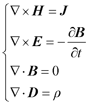
设圆柱形导体半径为r,对其建立如图1所示坐标系,有正弦交变电流沿着z轴方向流过,因此电流密度J和电场强度E只有y分量,且仅是x坐标的函数,即J=Jy(x)ey,E=Ey(x)ey。在忽略位移电流的影响后,可在磁准静态电磁场近似条件下讨论趋肤效应。磁准静态电磁场下的麦克斯韦方程组可以简化为
 (1)
(1)
式中,H为磁场强度,A/m;J为传导电流密度,A/m2;E为电场强度,V/m;B为磁通密度,T;D为电位移,C/m2;ρ为自由电荷体密度,C/m3。
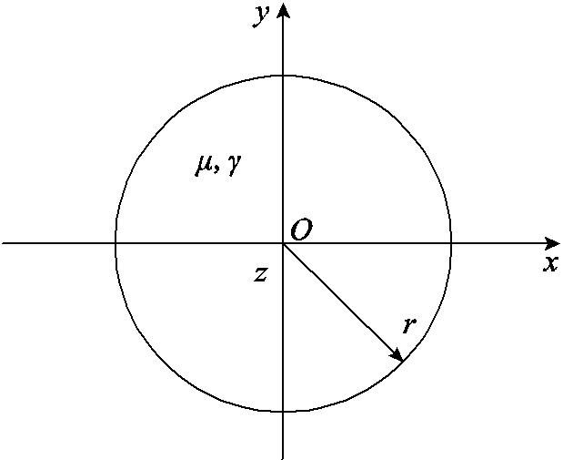
图1 有限大圆柱形导体截面
Fig.1 Cross-section of a finite large cylindrical conductor
对于各向同性线性介质,各量之间存在如式(2)所示的本构关系。
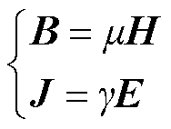 (2)
(2)
式中,μ为磁导率,H/m;g 为电导率,S/m。联立式(1)和式(2)可得
 (3)
(3)
设圆导体表面的电场强度和电流密度分别为E0和J0,式(3)所满足的边界条件为
 (4)
(4)
求解式(3)可以得到圆导体横截面沿着x轴方向电场强度和电流密度的分布为
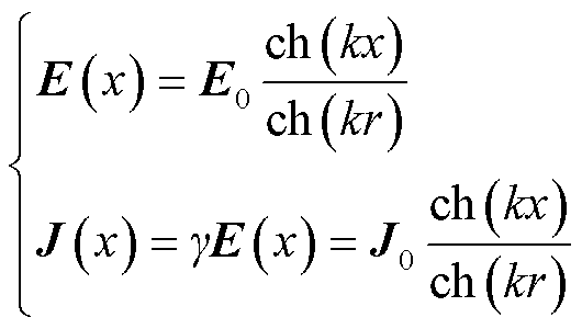 (5)
(5)
式中, 为传播常数,用以表征电磁波的传播特性;x的取值范围为0~r。
根据式(5)可得,随着距离圆心x增大,电流密度J(x)与圆导体表面电流密度J0的比值逐渐增大并最终趋于1,当x=r时,电流密度最大J(r)=J0,即圆柱形导体的趋肤效应。
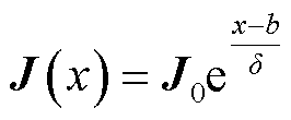
换流变压器套管多采用细长型空心圆导体作为载流结构,如图2所示,设导电杆内径为a,外径为b。对式(5)进行合理简化可得距离圆心x处的电流密度为
 (6)
(6)
式中,J0为套管导电杆外表面电流密度;δ为趋肤深度,根据趋肤深度在工程电磁场的公式可知,其随着频率的增加而减小。
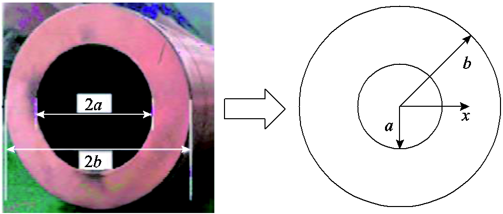
图2 套管载流导体横截面
Fig.2 Cross-section of the bushing conductor
对电流密度进行积分可以得到流过导电杆的电流为
 (7)
(7)
故套管导电杆表面的电流密度为
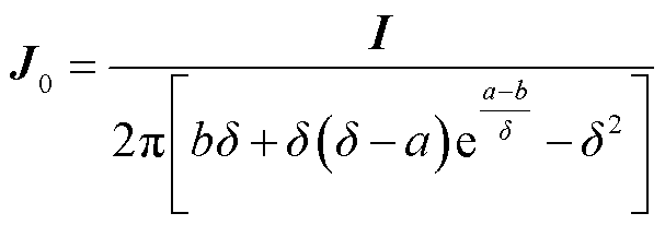 (8)
(8)
将式(8)代入式(6)中可以得到距离圆心x处导电杆的电流密度为
 (9)
(9)
根据焦耳定律的微分形式可以得到单位长度内导电杆的发热功率为

式中, 为导体电阻率。联立式(7)和式(10)可得套管导电杆单位长度i次谐波电阻Ri为
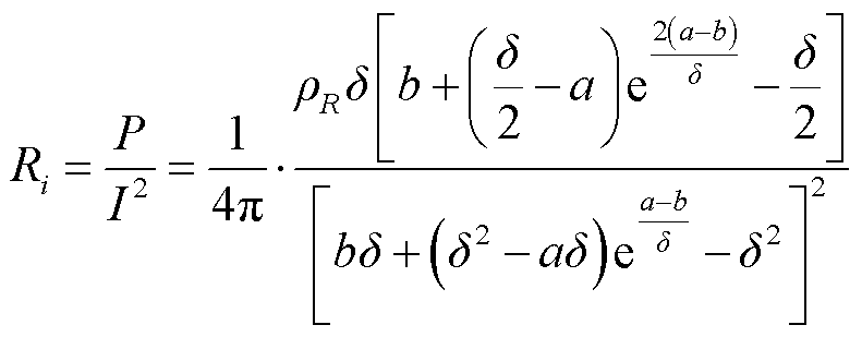 (11)
(11)
根据式(11)可得,随着谐波频率增加,趋肤深度减小,套管导电杆有效载流截面积减小,导电杆谐波电阻增大。
对于线性网络,导体有功损耗的计算可以将复杂电流进行傅里叶分解,依次求解单一频率下的导体损耗并叠加得到总有功损耗[25]。在计及趋肤效应的影响时,含有多次谐波分量的复杂电流下导体的有功损耗计算能否转换为单一频率谐波损耗的叠加,本节就该问题进行证明。
图3所示为宽度和高度均为单位长度的半无限大载流导体。其中正弦交变电流沿着yOz平面流过,计及趋肤效应的影响时载流导体中的电流密度为
 (12)
(12)
式中,Ji为导体通过单一频率 时,x=0处的电流密度;αi和βi分别为电磁波的衰减常数和相位常数且
 。
。
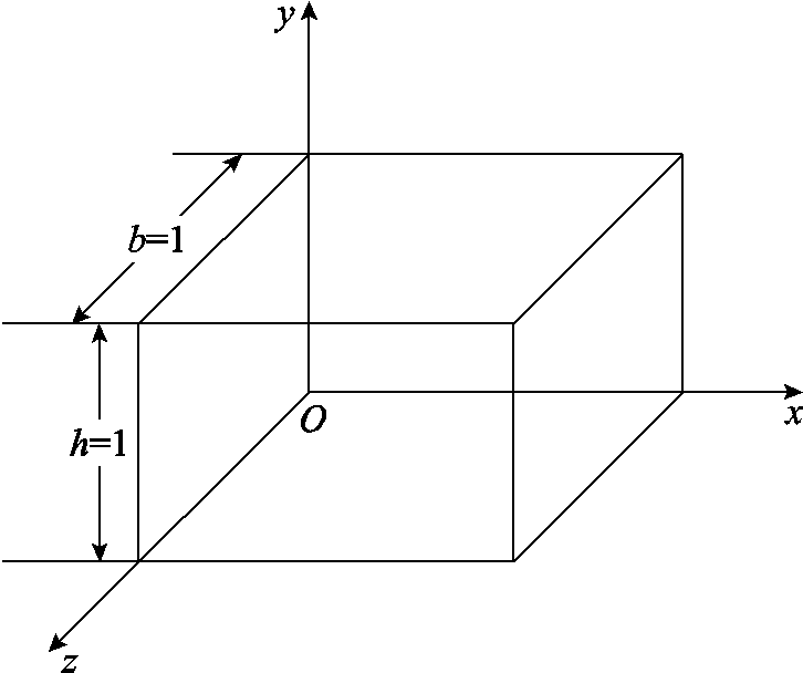
图3 单位长度半无限大载流导体模型
Fig.3 Model of a semi-infinite current carrying conductor unit length
因此单一频率电流下导体的瞬时功率为

根据定义,二端口网络的有功损耗为瞬时功率在一个周期内的平均值,因此单一频率电流下载流导体的有功损耗为
 (14)
(14)
当通过载流导体的电流为含有谐波的周期性非正弦电流时,载流导体的瞬时功率表达式变为
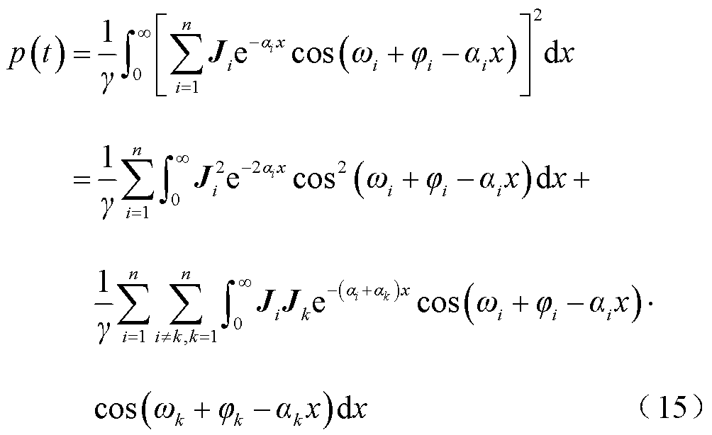
式(15)根据积化和差公式变形可得
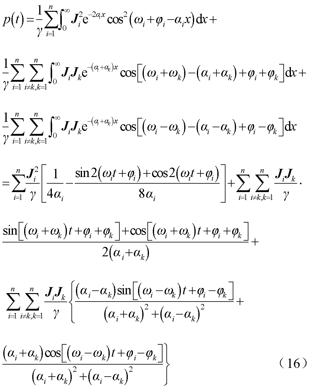
设基波电流角频率为 ,假设流过载流导体的谐波电流次数均为基波整数倍,设第n次谐波的频率为
 ,载流导体瞬时功率的计算公式可简化为
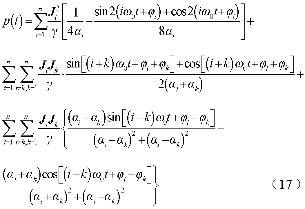
此时导体瞬时功率交流分量的频率均为基波电流频率的整数倍,对瞬时功率在一个基波周期内积分即可滤去所有的交流分量,即导体有功损耗中不含有交流分量。复杂电流下导体有功损耗的数学表达式为
 (18)
(18)
单一频率下载流导体的有功损耗如式(14)所示,因此载流导体通过含n次谐波的复杂电流下其有功损耗可以表示为各单一谐波频率下有功损耗值的总和,即
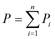 (19)
(19)
因此计及趋肤效应的影响下载流导体的谐波损耗满足可叠加性。基于上述分析,当载流导体内流过复杂电流时,对电流进行傅里叶变换,时域电流波形可以由各次谐波分量表示为
 (20)
(20)
式中,Ii为第i次谐波电流有效值;ji为第i次谐波电流的初相位。利用式(11)可以求得谐波频率为 时载流导体的谐波电阻Ri,因此复杂电流作用下计及趋肤效应的载流导体的有功损耗的数学表达式为
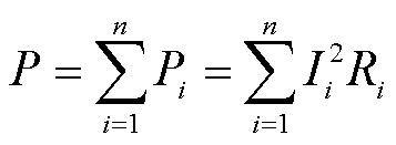 (21)
(21)
第2节推导了复杂电流作用下计及趋肤效应的载流导体有功损耗计算方法,即总有功损耗为各次谐波单独作用下的有功损耗之和,本节通过试验对该计算方法进行验证。
试验接线原理图如图4所示,包含可编程交流电源、被试导体、上位机、高精度示波器、电流传感器以及大功率电阻。可编程交流电源和大功率电阻如图5所示。可编程电源型号为Chroma 61705,三相总容量为12 kV×A,电压范围为0~300 V,频率范围为15~1.2 kHz。示波器型号为力科HDO6104,分辨率为12位,有效分辨率为8.7位,等效测量精度为0.24%,带宽1 GHz。大功率电阻采用RXG20波纹电阻,阻值为100 Ω,额定功率为10 kW,主要作用为限制回路电流,防止可编程电源过载。
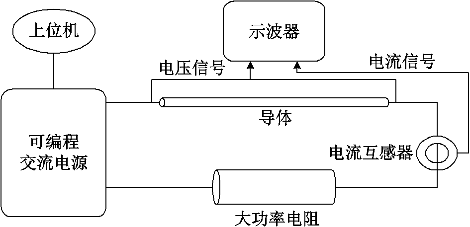
图4 可叠加性证明试验接线原理图
Fig.4 Test wiring diagram for proof of superposition
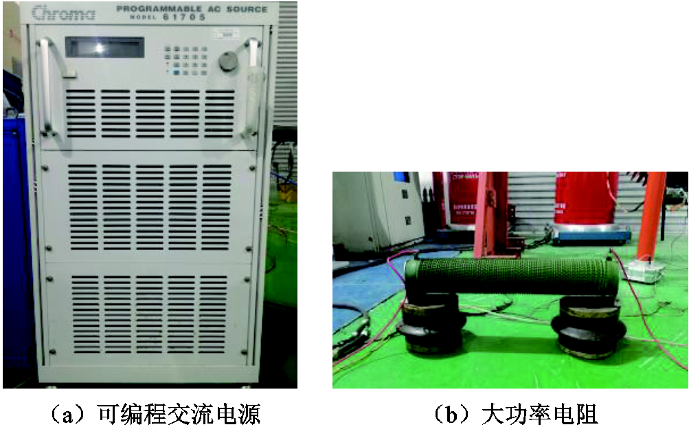
图5 可编程交流电源和大功率电阻
Fig.5 Programmable AC source and high-power resistor
在试验中,设定电源输出基波叠加谐波的复合电压,与实际电网电压的谐波特性不同,为使得谐波作用更为显著,更准确地验证谐波功率的可叠加性,试验中设定的各次谐波电压有效值和基波有效值相接近。试验步骤如下:
1)设定可编程交流电源输出指定复合电压,根据导体两端的电压和流过导体的电流波形乘积进行积分,得出导体在复合电流作用下的有功功率P0;同时对流过导体的复合电流进行傅里叶变换,得到不同频率fi下的电流有效值Ii。
2)设定可编程交流电源依次单独输出频率为fi的正弦电压,调节电压有效值使得电流大小为Ii,根据导体两端的电压和流过导体的电流波形乘积进行积分,计算出单次谐波下的有功损耗Pi。
3)对Pi叠加得出各单次谐波电流下的有功功率之和P,最后将P0和P进行对比分析。
本文共进行了3组对比试验,复合电流作用下各组试验中导体两端的电压以及流过导体的电流波形分别如图6a~图6c所示。可叠加性试验中各次谐波的有效值及有功损耗计算结果见表1。
定义导体在复合电流下的有功功率和各次谐波单独作用下有功功率总和之差的绝对值与复合电流下有功功率的比值为相对误差,即
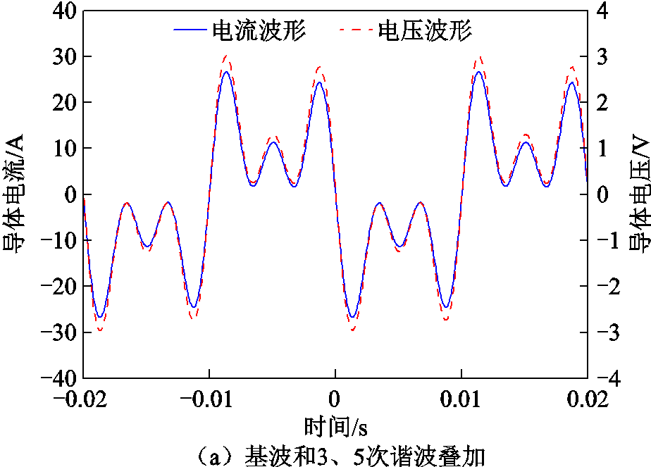
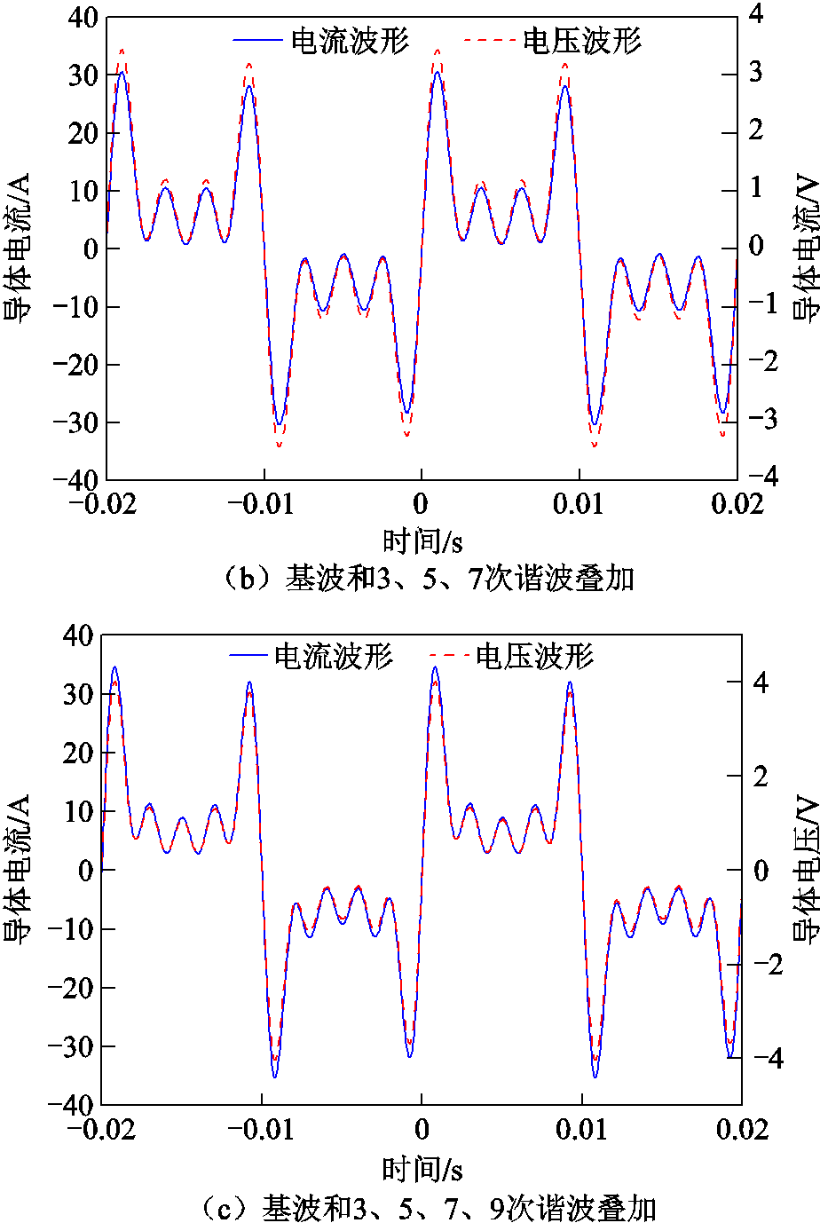
图6 可叠加性试验波形
Fig.6 Superimposability test waveforms
 (22)
(22)
表1 各组试验的谐波设置和有功损耗计算表
Tab.1 Parameters of harmonic voltage and active loss in each test
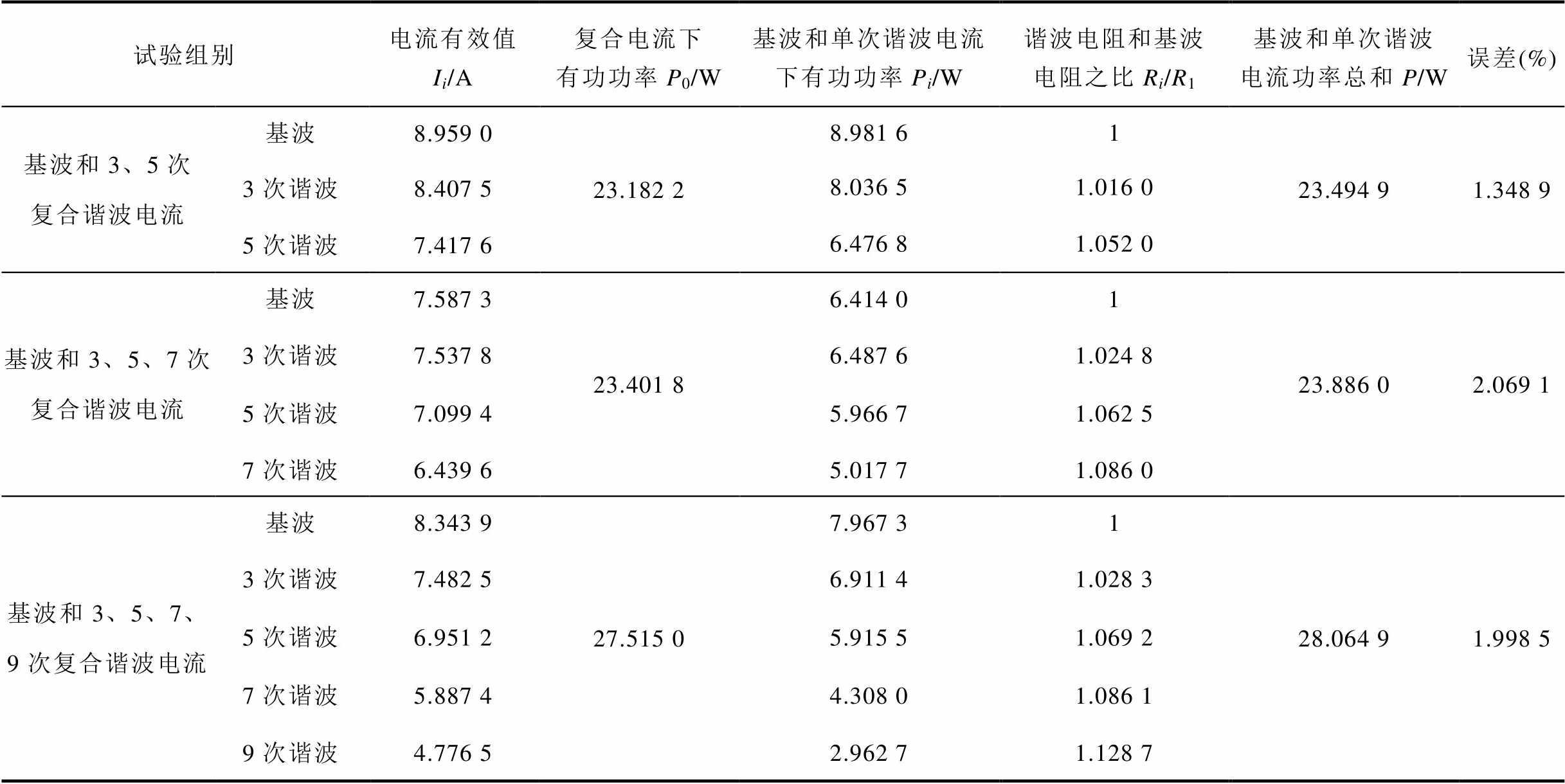
试验组别电流有效值Ii/A复合电流下有功功率P0/W基波和单次谐波电流下有功功率Pi/W谐波电阻和基波电阻之比Ri/R1基波和单次谐波电流功率总和P/W误差(%) 基波和3、5次复合谐波电流基波8.959 023.182 28.981 6123.494 91.348 9 3次谐波8.407 58.036 51.016 0 5次谐波7.417 66.476 81.052 0 基波和3、5、7次复合谐波电流基波7.587 323.401 86.414 01 23.886 02.069 1 3次谐波7.537 86.487 61.024 8 5次谐波7.099 45.966 71.062 5 7次谐波6.439 65.017 71.086 0 基波和3、5、7、9次复合谐波电流基波8.343 927.515 07.967 3128.064 91.998 5 3次谐波7.482 56.911 41.028 3 5次谐波6.951 25.915 51.069 2 7次谐波5.887 44.308 01.086 1 9次谐波4.776 52.962 71.128 7
在三组对比试验中,复合电流产生的有功功率P0与各次谐波电流单独作用下的有功功率之和P之间的相对误差均在3%以内,证明了计及趋肤效应下导体谐波功率的可叠加性。
为了研究实际工况下套管载流导体的谐波损耗特性,本文参考云广±800 kV特高压直流输电系统的实际结构与参数,基于PSCAD/EMTDC电磁暂态仿真软件建立了典型直流系统的仿真模型。云广特高压直流输电系统仿真模型如图7所示,具体包括整流侧与逆变侧的换流阀、换流变压器、平波电抗器以及直流和交流滤波器等[26-27]。整流侧与逆变侧的换流阀采用两极对称的布置方式,每极由两个六脉动整流桥串联组成。仿真得到极1端Y/Y换流变阀侧套管的电流波形如图8所示。
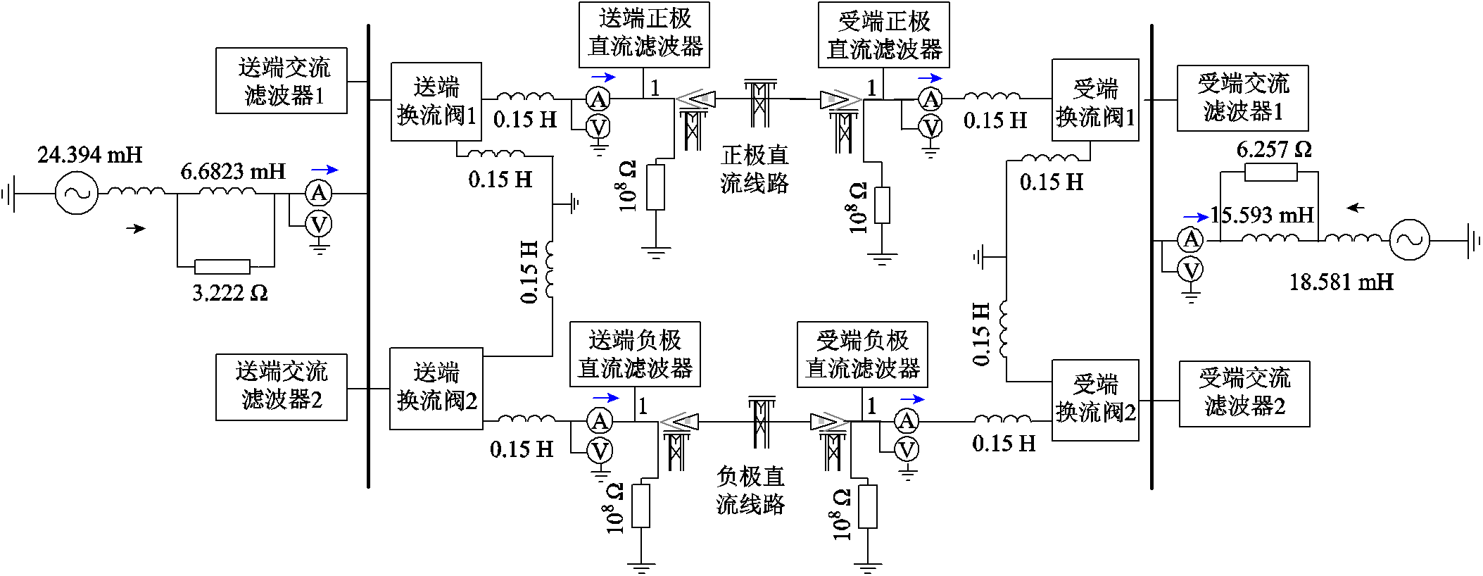
图7 云广特高压直流输电系统仿真模型
Fig.7 The simulation model of Yunnan-Guangdong UHVDC system
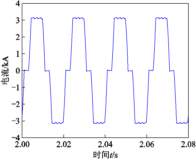
图8 换流变压器阀侧套管电流波形
Fig.8 The current waveform of valve-side bushing of converter transformer
通过对换流变阀侧套管电流波形进行傅里叶分解得到电流频谱如图9所示。由电流频谱图可以看出,套管载流导体中除流过基频电流外,同时含有大量的谐波电流,其中以5、7、11、13、17、19等6k±1次特征谐波分量为主,非特征次谐波电流含量极小。
分析电力谐波时通常采用总谐波畸变率来表征谐波分量对基波的畸变程度,总谐波畸变率定义为各次谐波有效值二次方和的平方根与基波分量比值的百分数。电流总谐波畸变率为
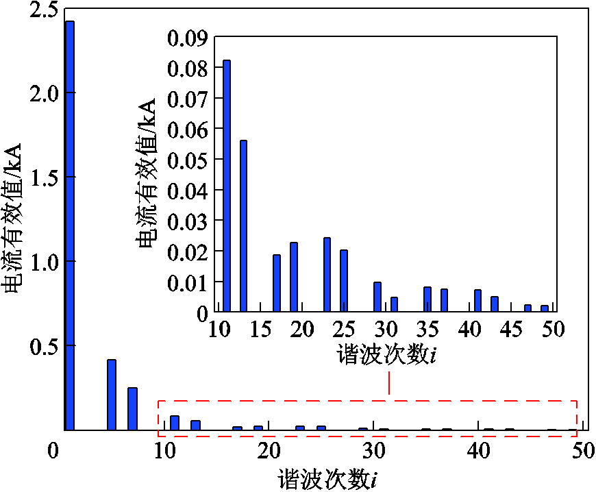
图9 换流变压器阀侧套管电流频谱
Fig.9 Frequency spectrum of valve side bushing current of converter transformer
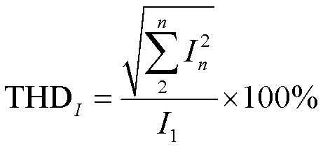 (23)
(23)
根据高压直流输电设备设计与考核的相关标准,负载电流中的谐波次数通常要考虑到第49次,综合考虑计算准确性与计算效率,本文截取了前50次谐波电流分量进行载流结构有功损耗计算。前50次谐波重构的电流波形与实际电流波形对比如图10所示,根据式(22)计算得到电流总谐波畸变率为2.09%。仿真电流接近±3.125 kA与云广±800 kV特高压直流输电工程的额定电流基本相同,能够很好地模拟云广特高压直流输电系统换流变压器阀侧套管的谐波电流,具有较好的代表性和通用性。
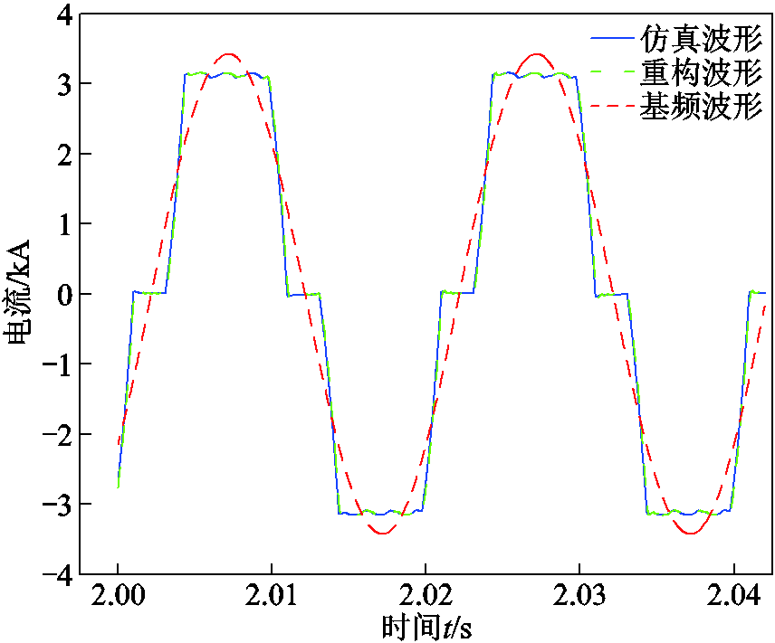
图10 重构波形与实际仿真波形对比
Fig.10 Comparison between reconstructed waveform and actual simulation waveform
根据套管生产厂家提供的设计手册,云广±800 kV特高压直流输电线路换流变压器阀侧套管导杆内直径为80 mm,外直径为155 mm,导杆长度为9 744 mm,材质为纯铜。结合1.2节中式(11)可以得到套管载流导体谐波电阻随着电流频率的变化规律如图11所示,随着电流频率的增加,导体谐波电阻不断增大,与表1试验结果中谐波电阻的变化基本一致,证明了公式推导的正确性。
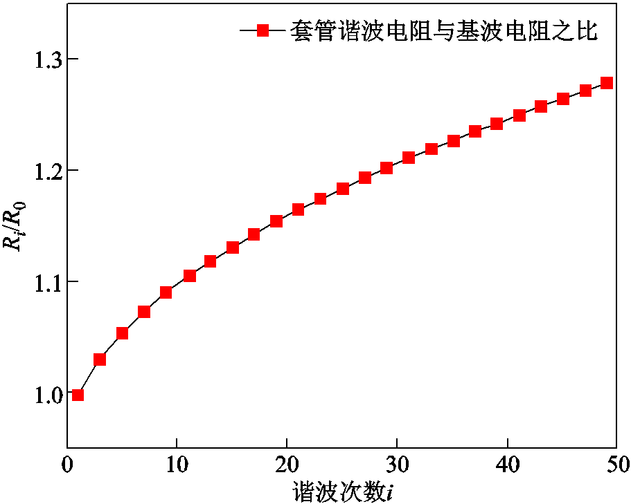
图11 不同频率电流下套管载流导体谐波电阻和基波电阻比值
Fig.11 Ratio diagram of harmonic resistance and fundamental resistance of the current-carrying conductor under different frequencies
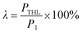
计及趋肤效应下套管载流导体在基波和各次谐波电流作用下的有功损耗如图12所示,记基波电流有功损耗为 ,各次谐波电流叠加得到谐波电流总有功损耗记为PTHL。定义套管载流导体各次谐波电流产生的总有功损耗PTHL与基波电流有功损耗
 比值的百分数为谐波电流有功损耗增强系数λ,即
 (24)
(24)
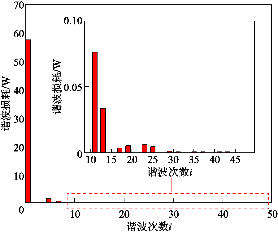
图12 谐波电流下有功损耗分布
Fig.12 Spectrum of active loss under harmonic current
对于文中所分析的换流变压器阀侧套管,其谐波电流有功损耗增强系数为4.33%,即占基波电流2.09%的谐波电流在套管载流导体上产生的损耗占基波损耗的4.33%,在趋肤效应影响下谐波电流对套管载流结构有功损耗具有显著增强作用。针对这一问题的解决方法,需结合实际的应用场景及本文内容进行分析。①针对电力设备,可采用滤波、补偿等措施,降低电流中的高频电流含量,从而使趋肤深度增大,有效载流截面增大,损耗减小;②针对输电线路,可采用分裂导线使电流分布较为均匀,降低趋肤损耗;③针对高频电流,可采用表面覆盖高导电率金属膜来抑制趋肤效应。今后将针对解决趋肤效应下有功损耗增加问题进行更深入的分析研究。
1)基于电磁场理论,结合套管载流导体实际结构,建立了计及趋肤效应影响的套管载流结构谐波电阻计算模型。
2)理论推导了谐波电流作用下计及趋肤效应的套管载流导体有功损耗的可叠加性;搭建试验平台,通过三组对比试验进行了验证。
3)搭建了直流输电仿真平台,对实际换流变阀侧套管谐波损耗计算,结果显示占基波电流2.09%的谐波电流在套管载流导体上产生的损耗占基波损耗的4.33%,趋肤效应影响下谐波对套管载流导体有功损耗具有显著增强作用。
参考文献
[1] 谢小荣, 贺静波, 毛航银, 等. “双高”电力系统稳定性的新问题及分类探讨[J]. 中国电机工程学报, 2021, 41(2): 461-474.
Xie Xiaorong, He Jingbo, Mao Hangyin, et al. New issues and classification of power system stability with high shares of renewables and power electronics[J]. Proceedings of the CSEE, 2021, 41(2): 461-474.
[2] 张明, 袁钥. 三电平有源滤波器在电压源型负载系统中的仿真和应用[J]. 电气技术, 2021, 22(8): 29-33.
Zhang Ming, Yuan Yue. Simulation and application of three-level active power filter in voltage source load system[J]. Electrical Engineering, 2021, 22(8): 29-33.
[3] 张宁, 马国明, 关永刚, 等. 全景信息感知及智慧电网[J]. 中国电机工程学报, 2021, 41(4): 1274-1283. Zhang Ning, a Guoming, Guan Yonggang, et al. Panoramic information perception and intelligent grid[J]. Proceedings of the CSEE, 2021, 41(4): 1274-1283.
[4] 盛逸标, 林涛, 陈宝平, 等. 面向新能源外送系统次/超同步振荡的控制器参数协调优化[J]. 电工技术学报, 2019, 34(5): 983-993.
Sheng Yibiao, Lin Tao, Chen Baoping, et al. Coordination and optimization of controller parameters for subsynchronous/super-synchronous oscillation in new energy delivery systems[J]. Transactions of China Electrotechnical Society, 2019, 34(5):983-993.
[5] 李明节, 于钊, 许涛等. 新能源并网系统引发的复杂振荡问题及其对策研究[J]. 电网技术, 2017, 41(04): 1035-1042.
Li Mingjie, Yu Zhao, Xu Tao, et al. Study of complex oscillation caused by renewable energy integration and its solution[J]. Power System Technology, 2017, 41(4): 1035-1042
[6] 周峰, 李鹤, 李文婷, 等. 大电流测量传感技术综述[J]. 高电压技术, 2021, 47(6): 1905-1920.
Zhou Feng, Li He, Li Wenting,etal. Review of high current measurement and sensing technology[J]. High Voltage Engineering, 2021, 47(6): 1905-1920.
[7] 丁宁, 穆海宝, 梁兆杰, 等. 水分对干式套管环氧浸渍纸材料介电特性的影响[J]. 电工技术学报 2022, 37(11): 2716-2724.
Ding Ning, Mu Haibao, Liang Zhaojie, et al. Effects of moisture on dielectric properties of epoxy resin impregnated paper for dry-type bushing[J]. Transactions of China Electrotechnical Society, 2022, 37(11): 2716-2724.
[8] 赵建利, 姚顺, 岳永刚, 等. 500 kV SF6瓷质套管多工况仿真与故障分析[J].电工技术学报, 2021, 36(增刊2): 736-745.
Zhao Jianli, Yao Shun, Yue Yonggang, et al. Multi-condition simulation and fault analysis of 500 kV SF6 porcelain casing[J]. Transactions of China Electrote-chnical Society, 201, 36(S2): 736-745.
[9] 夏军, 张璧辉, 杨知非, 等. 电力谐波对变压器套管电容芯子介质损耗的影响研究[J]. 电瓷避雷器, 2020(1): 222-227.
Xia Jun, Zhang Bihui, Yang Zhifei, et al. Study on the influence of power harmonic on the dielectric loss of transformer capacitive bushings[J]. Insulators and Surge Arresters, 2020(1): 222⁃227.
[10] 张施令, 彭宗仁, 吴昊. ±800 kV换流变压器阀侧干式套管的损耗分析[J]. 电网技术, 2014, 38(7): 1758-1764.
Zhang Shiling, Peng Zongren, Wu Hao. Analysis on power loss of valve-side RIP bushing for ± 800 kV converter transformer[J]. Power System Technology, 2014, 38(7): 1758-1764
[11] 柳百毅, 陈为. 改进的磁元件圆导线绕组高频损耗模型[J]. 中国电机工程学报, 2019, 39(9): 2795-2803.
Liu Baiyi, Chen Wei. Improved high frequency loss model of circular wire winding for magnetic components[J]. Proceedings of the CSEE, 2019, 39(09): 2795-2803.
[12] 林德清, 顾伟, 王元凯, 等. 基于动态时间弯曲空间距离度量的电能质量综合评估[J]. 电网技术, 2013, 37(2): 562-567.
Lin Deqing, Gu Wei, Wang Yuankai, et al. Synthetic evaluation of power quality based on dynamic time warping spatial distance measurement[J]. Power System Technology, 2013, 37(2): 562-567.
[13] 李泓泽, 郭森, 唐辉, 等. 基于改进变权物元可拓模型的电能质量综合评价[J]. 电网技术, 2013, 37(3): 653-659.
Li Hongze, Guo Sen, Tang Hui, et al. Comprehensive evaluation on power quality based on improved matter-element extension model with variable weight[J]. Power System Technology, 2013, 37(3): 653-659.
[14] 王威望, 李睿喆, 何杰峰, 等. 快速陡脉冲重复电场下高频变压器绝缘介质损耗与冲击能量积聚特性[J]. 电工技术学报, 2023, 38(5): 1206-1216.
Wang Weiyi, Li Ruizhe, He Jiefeng, et al. Dielectric loss and impact energy accumulation of high frequency transformer insulation under rapidly repetitive pulsed voltages[J]. Transactions of China Electrotechnical Society, 2023, 38(5): 1206-1216.
[15] Akbari M, Allahbakhshi M, Mahmoodian R. Heat analysis of the power transformer bushings in the transient and steady states considering the load variations[J]. Applied Thermal Engineering, 2017, 121: 999-1010.
[16] Jyothi N S, Ramu T S, Mandlik M. Temperature distribution in resin impregnated paper insulation for transformer bushings[J]. IEEE Transactions on Dielectrics and Electrical Insulation, 2010, 17(3): 931-938.
[17] 黄天超, 王泽忠. 特高压换流变压器拉板损耗的频率特性分析[J]. 电工技术学报, 2021, 36(19): 4132-4139.
Huang Tianchao, Wang Zezhong. Frequency characteristic analysis of flitch plate losses in UHV converter transformer[J]. Transactions of China Electrotechnical Society, 2021, 36(19): 4132-4139.
[18] 刘慧娟, 张竞雄, 陈艺端, 等. 二维涡流磁场等效电路的矩阵分析方法[J]. 电工技术学报, 2013, 28(6): 73-80.
Liu Huijuan, Zhang Jingxiong, Chen Yiduan, et al. Matrix analysis method of equivalent circuit in 2-D eddy-current magnetic field[J]. Transactions of China Electrotechnical Society, 2013, 28(6):73-80.
[19] 谭又博, 余小玲, 臧英, 等. 谐波电流对换流变压器绕组损耗及温度分布特性的影响[J].电工技术学报, 2023, 38(2): 542-553.
Tan Youbo, Yu Xiaoling, Zang Ying, et al. The influence of harmonic current on the loss and temperature distribution characteristics of a converter transformer winding[J]. Transactions of China Electrotechnical Society, 2023, 38(2): 542-553.
[20] 李琼林, 邹磊, 刘会金, 等. 电力变压器谐波损耗仿真计算与实验研究[J].电网技术, 2013, 37(12): 3521-3527.
Li Qionglin, Zou Lei, Liu Huijin, et al. Simulation calculation and experimental research on harmonic losses in power transformers[J]. Power System Technology, 2011, 35(11): 120-124.
[21] 周克定, 张文灿. 电工理论基础[M]. 北京: 高等教育出版社, 1994.
[22] 冯慈璋, 马西奎. 工程电磁场导论[M]. 北京: 高等教育出版社, 2000.
[23] 吴命利, 范瑜. 圆导线内阻抗的数值计算[J]. 电工技术学报, 2004, 19(3): 52-58.
Wu Mingli, Fan Yu. Numerical calculations of internal impedance of cylindrical conductors[J]. Transaction of China Electrotechnical Society, 2004, 19(3): 52-58.
[24] 张长庚, 田亚坤, 李永建, 等. 谐波及直流偏磁下变压器叠片式磁屏蔽杂散损耗模拟与验证[J]. 电工技术学报, 2022, 37(15): 3733-3742.
Zhang Changgeng, Tian Yakun, Li Yongjian et al. Modeling and validation of stray-field loss in laminated magnetic shield of transformer under harmonics and DC bias [J]. Transactions of China Electrotechnical Society, 2022, 37(15): 3733-3742.
[25] 王超. 谐波对导体电阻的影响及实验研究[D]. 北京: 华北电力大学, 2017.
[26] 陈仕龙, 束洪春, 叶波, 等. 云广±800 kV特高压直流输电系统精确建模及仿真[J]. 昆明理工大学学报(自然科学版), 2012, 37(2): 43-48, 60.
Chen Shiling, Shu Hongchun, Ye Bo, et al. Accurate modeling and simulation of Yunnan-Guangdong ±800 kV UHVDC transmission system[J]. Journal of Kunming University of Science and Technology (Natural Science Edition), 2012, 37(2): 43-48, 60.
[27] 裴旵, 王振, 吕思颖, 等. 基于PSCAD的云广特高压直流输电系统仿真模型建立[J]. 广西电力, 2015, 38(4): 14-17, 80.
Pei Chan, Wang Zhen, Lü Siying, et al. Establishment of Yun-guang UHVDC system simulation model based on PSCAD[J]. Guangxi Electric Power, 2015, 38(4): 14-17, 80.
Abstract With the increasing proportion of new energy in the power grid and the access characteristics of a large number of power electronic equipment, the problem of new power system harmonics becomes increasingly significant. The actual current passing through the current carrying structure of power equipment such as sleeve contains a large number of high order harmonics. As a very important electrical equipment in power system, high voltage bushing is used for ground insulation of incoming and outlet lines of power equipment such as transformers, reactors and circuit breakers, and high voltage circuit crossing walls. This paper takes the active power loss of bushing under the action of harmonics as the starting point, and considers the enhancement effect of skin effect on harmonic loss of current-carrying conductor. The active power loss characteristics of casing current carrying structure under harmonic current are studied.
Firstly, based on the basic electromagnetic field theory, the calculation model of the harmonic resistance and active power loss of the current carrying structure of the casing is established, and the superposition of the active power loss of the casing under different harmonic components and the correctness of the calculation method of the active power loss of the current carrying structure under the consideration of skin effect are verified theoretically and experimentally. Finally, based on the current waveform obtained by simulation, the active power loss of the current carrying structure of the casing was quantitatively calculated, and the enhancement coefficient of the harmonic current on the active power loss of the current carrying structure under skin effect was proposed to correct the active power loss of the current carrying structure of the casing.
From a theoretical point of view, the superposition of the active power loss of the current structure and the change rule of harmonic resistance were verified by taking into account the influence of skin effect and the effect of harmonic current, and the superposition test platform was built. Under the three groups of comparison experiments, the relative error between the active power P0 generated by the composite current and the sum of the active power P under the harmonic current was all within 3%. Moreover, the harmonic resistance of the casing increases with the increase of harmonic frequency. The superposition of harmonic loss of the conductor is proved from the test point of view. Based on the actual HVDC system put into operation in Yunguang, the actual current waveform of the rheological casing is simulated, and the enhancement coefficient of harmonic current on active power loss under skin effect is proposed, and the active power loss of the current carrying structure of the casing is quantitatively calculated. For the current waveforms analyzed in the paper and simulated, the harmonic resistance increases by 0~28% within 50 harmonics, and the active power loss enhancement coefficient is 4.33%. For other casing current-carrying structures, the active power loss can be quantitatively calculated using the above method according to the size of the current-carrying structure, the material and the current waveform flowing through it.
The following conclusions can be drawn from the simulation analysis: (1) Based on the electromagnetic field theory and combined with the actual structure of the current carrying conductor in the casing, the calculation model of the harmonic resistance of the current carrying structure of the casing is established taking into account the skin effect. (2) The superposition of the active power loss of the current-carrying conductor under the action of harmonic current and skin effect is theoretically deduced; The test platform was built and verified by 3 groups of comparative tests. (3) The HVDC transmission simulation platform was established. The calculation results of harmonic power loss of the casing at the side of the rheological valve showed that the loss of harmonic current on the casing current-carrying conductor accounted for 4.33% of the fundamental power loss, which accounted for 2.09% of the fundamental current. Under the skin effect, the harmonic current significantly enhanced the active power loss of the casing current-carrying conductor.
keywords:Skin effect, bushing, active power loss, harmonic
中图分类号:TM855
DOI:10.19595/j.cnki.1000-6753.tces.211633
收稿日期 2021-10-11
改稿日期 2022-03-12
杜 林 男,1971年生,博士,教授,博士生导师,研究方向为高电压试验技术、电气设备绝缘在线监测及故障诊断等。E-mail:dulin@cqu.edu.cn(通信作者)
张 科 男,1996年生,硕士研究生,研究方向为电气设备绝缘在线监测及局部放电E-mail:2240501838@qq.com
(编辑 郭丽军)