
图1 无刷双馈发电机结构的等效示意图
Fig.1 Equivalent schematic diagram of brushless doubly fed machine
摘要 对于并网运行的无刷双馈风力发电系统,在电网电压瞬时对称跌落时,相当于在并网点突加一个反向电压源。采用传统双闭环PI控制策略时,通过在复频域推导功率绕组和控制绕组瞬态电流的表达式,得出其超调量和振荡时间受发电机参数、电网电压的跌落程度、相位及转速的影响。提出一种状态反馈控制策略,构建以功率绕组和控制绕组电流为状态变量的状态模型。通过反馈矩阵在输入端加入状态变量,改变了发电机系统矩阵的参数,即改变了发电机的等效参数。极点分布图显示状态反馈策略下极点较传统控制极点大幅左移,则系统加速收敛,同时减小了振幅,支撑系统故障过程平稳过渡。最后,通过额定工况下电网电压跌落至20%时的实验波形,验证了状态反馈控制的可行性。
关键词:无刷双馈电机 风力发电 电网电压跌落 振荡超调 状态反馈
无刷双馈电机是一种新型交流电机,由于取消了电刷和集电环,维护成本低,可靠性更高,应用前景非常广泛[1-4]。在国家十四五规划提出降低碳排放和加大清洁能源比重的背景下,对无刷双馈电机在风力发电领域的应用与控制研究显得尤为重要。
近年来,随着风电总装机容量的不断增加,电网电压跌落期间要求发电系统不间断运行,主动式Crowbar在吸收瞬时能量的同时可实现发电系统向电网输出无功电流,但会带来成本方面的问题。因此改进主动式Crowbar装置的保护方法或者展开无Crowbar控制技术的研究势在必行。
基于上述要求,已有部分研究人员开展了无刷双馈风力发电机组的低电压穿越的相关研究[5-11]。包括动态运行分析、增加硬件设备和无Crowbar控制。
文献[5]提出了一种无刷双馈发电机的简化动态T形电路,并对电网电压跌落时功率绕组和控制绕组的物理量(磁通、电流和电压)进行了详细的推导,并得出结论:减小定子功率绕组和控制绕组电流的振荡幅值取决于发电机的绕组设计,而不是改进控制策略。
有学者在无刷双馈发电机和控制系统之间安装串联动态电阻器或Crowbar以吸收瞬时大功率[6],减小了控制绕组电流的超调量,其缺点是导致系统成本的增加。
关于无Crowbar控制技术方面,文献[7-8]提出电网电压正常时功率绕组的有功电流设为额定值,无功电流设置为0。而当电网电压发生对称跌落时,有功和无功电流的指令值分别设置为0和额定值,向电网输出无功功率,但这些控制策略仍会引起功率绕组和控制绕组电流的超调和振荡。在文献[9]中,控制绕组的电压指令值叠加功率绕组、控制绕组和转子绕组磁通变化率的补偿项,仿真结果表明,该方法可以有效地降低电网电压骤降时功率绕组、控制绕组和转子绕组电流的振荡幅度。文献[10]提出了一种虚拟同步发电机瞬时电流补偿的方法,减少了电网故障时控制绕组反电动势的幅值。文献[11]提出了一种基于磁链跟踪的无Crowbar低电压穿越控制策略,实验结果表明,当无刷双馈发电机转速为最大值,并且电网电压跌落至0 V时,控制绕组电流峰值可限制在额定值的两倍以内,但文章缺少对比分析。
鉴于当前无刷双馈风力发电机的低电压穿越研究存在一些不足,本文更加深入分析地电网电压瞬时对称跌落时无刷双馈风力发电机的动态运行特性。在复频域推导功率绕组和控制绕组瞬态电流的表达式,得出其超调量和振荡时间受发电机自身参数、电网电压跌落程度、相位及转速的影响。并提出一种优化控制策略,即状态反馈控制,以改善控制系统的瞬态运行特性。
状态反馈控制是一种优化控制策略,不增加系统的维度。利用原系统中可以直接测量的状态变量作为附加输入信号,从而改变了系统的特征方程,即重新配置极点,改变系统的收敛速度,进一步改善控制系统的动态性能。
已有文献采用状态反馈控制应用于双馈发电机和同步发电机系统,实现不同的控制目标。文献[12]提出双馈发电机的状态反馈解耦控制,实现针对电网相位、角频率和阻抗偏差的独立解耦控制,提高了对低频振荡的抑制能力。文献[13]提出状态反馈与扰动观测相结合的方法,提升了双馈发电系统的稳态与瞬态特性,使系统的有功功率和无功功率响应速度加快。文献[14]提出一种双馈发电系统降阶的状态反馈与状态估计结合法,相比于状态估计与矢量控制结合法,降低了运算和控制的复杂度,精度更高,响应更快。文献[15]提出状态反馈与扰动观测相结合的方法,应用于永磁同步发电系统,结果显示电流观测器的精度和转速阶跃输入的响应优于传统PI控制。文献[16]提出状态反馈估计永磁同步电机的位置,提升了系统的鲁棒性。
由于电网电压瞬时跌落时无刷双馈风力发电机功率绕组和控制绕组瞬态电流的超调量和振荡时间受发电机自身参数的影响,对于一台设计制造成型的无刷双馈发电机,本身电机参数无法改变,可考虑将状态反馈控制应用于无刷双馈风力发电机的电网故障工况。根据发电机的状态空间方程,引入状态反馈后,可改变系统的控制结构,改变发电机的系统矩阵,重新配置系统极点,使系统加速收敛,同时减小振幅。从物理意义上讲,相当于改变其等效电机参数,即增大其等效瞬态阻抗,抑制了功率绕组和控制绕组瞬态电流和电磁转矩的振荡超调,提升系统的抗扰动能力,增强其鲁棒性。最后,电网电压瞬时对称跌落到20%,展开状态反馈控制策略与传统双闭环PI矢量控制策略的实验,通过发电机功率绕组和控制绕组电流以及磁转矩的对比,验证了状态反馈策略的可行性和有效性。
绕线转子无刷双馈电机定子的两套绕组,分别称作功率绕组和控制绕组,但极对数不一致。其转子只有一套绕组,相当于反相序连接的两套绕组,可以感应出两个极对数不同旋转方向相反的磁场,分别与定子两套绕组的磁场耦合[17],无刷双馈发电机结构的等效示意图如图1所示。

图1 无刷双馈发电机结构的等效示意图
Fig.1 Equivalent schematic diagram of brushless doubly fed machine
设功率绕组极对数为pp,其电流矢量的角频率为ωp,控制绕组极对数为pc,角频率为ωc,定子两个绕组产生的磁场能在转子绕组感应出的频率分别为frp和frc的电流。
而实际上转子只有一套绕组,因此两种电流产生的磁场旋转方向是相反的,即2πfrp=-2πfrc,从而得到
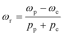 (1)
(1)
当ωc取正、负和0时,分别得到电机亚同步速度、超同步速度和自然同步速。
由于无刷双馈发电机的三相原始模型过于复杂[18],且现有动态数学模型包含转子回路方程,分析和求解同样困难,通常情况下需要简化。根据电路理论,列出无刷双馈电机折算转子回路后的简化动态数学模型,功率绕组同步速矢量空间发电机的动态数学模型如式(2)~式(7)所示[19-20]。功率绕组和控制绕组均采用电动机惯例。
 (2)
(2)
 (3)
(3)
 (4)
(4)
 (5)
(5)
 (6)
(6)
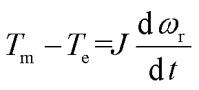 (7)
(7)
式中,up和uc分别为功率绕组电压和控制绕组的电压;ψp和ψc分别为功率绕组磁链和控制绕组的磁链;ip和ic分别为功率绕组和控制绕组电流;Rsp和Rsc分别为功率绕组和控制绕组每相电阻值;ωr为转子的机械角速度;p为微分算子;Lsp和Lsc分别为功率绕组和控制绕组的等效两相绕组自感;Mpc为同轴等效绕组的互感;θ为功率绕组和控制绕组电流的电气夹角;Tm为机械转矩;Te为电磁转矩;J为转动惯量。简化模型中参数与实际参数关系为
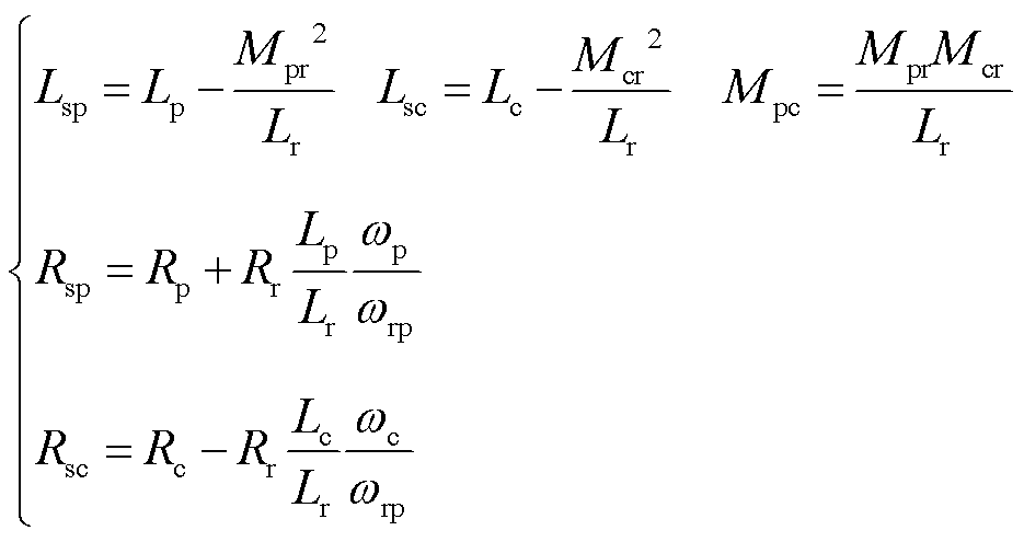 (8)
(8)
式中,Rp、Rc和Rr分别为原始模型中功率绕组、控制绕组和转子绕组每相电阻值;Lp、Lc和Lr分别为原始模型中功率绕组、控制绕组和转子绕组每相的自感;Mpr为原始模型中功率绕组和转子绕组的互感;Mcr为原始模型中控制绕组和转子绕组的互感。
通过电网电压定向控制策略[21],无刷双馈风力发电机的控制框图如图2所示。图2中,变量的下标d和q表示功率绕组同步速dq坐标系的dq轴分量。功率绕组电压在dq坐标系与矢量空间的关系为:up=upd+jupq,其他矢量如电流和磁链类推。P和Q表示功率绕组的有功和无功功率。功率绕组同步速矢量空间中电机的矢量如图3所示。
对于并网稳定运行的无刷双馈风力发电机及控制系统来讲,风电场并网点电网电压发生瞬时对称跌落,相当于并网点突加一个反向电压源,该反向电压源可视为一个相对于原并网点电压反向的电压阶跃信号,必然导致发电机功率绕组、控制绕组和转子绕组电流的振荡和超调,进一步引起电磁转矩突变,造成发电系统的机械与电气冲击。
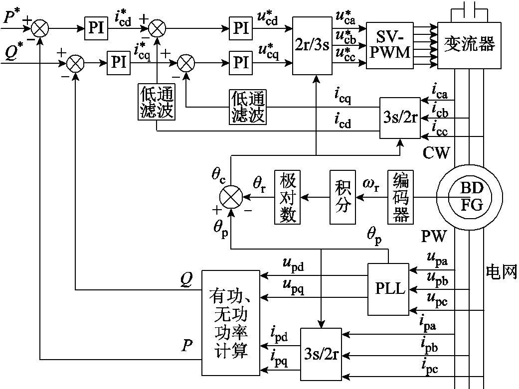
图2 无刷双馈发电机常规控制策略框图
Fig.2 The conventional control block diagram of BDFG
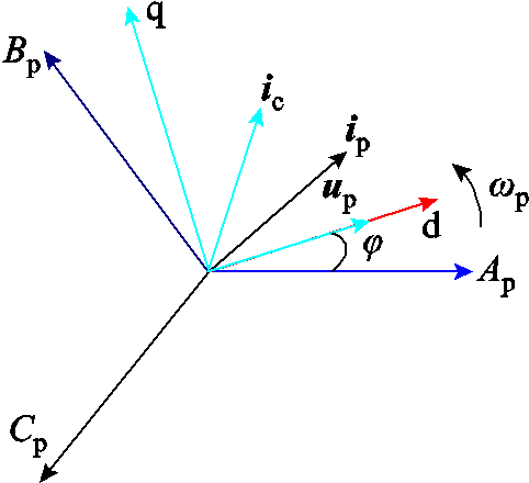
图3 功率绕组同步速矢量空间发电机的矢量图
Fig.3 Vector diagram of BDFG in PW vector space
若发电机处于稳定运行状态,令式(2)~式(5)方程组中微分项为0,得到稳态方程,并根据稳态方程得到稳态等效电路如图4所示。
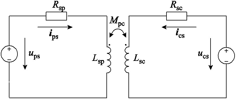
图4 无刷双馈发电机稳态等效电路图
Fig.4 Steady-state equivalent circuit diagram of BDFG
根据稳态方程,求得稳态运行发电机功率绕组和控制绕组电流的解析表达式为[22]
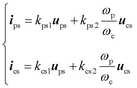 (9)
(9)
式中,ups、ucs、ips和ics分别为稳态电压和电流;稳态系数kps1、kps2、kcs1和kcs2为
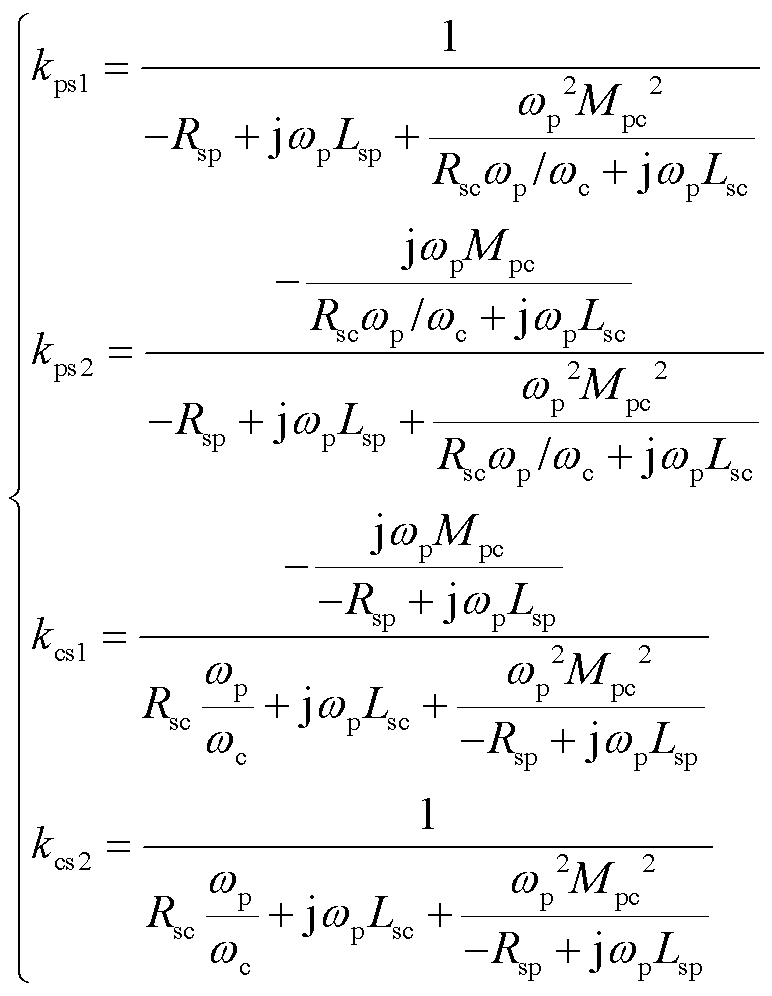 (10)
(10)
电网电压发生瞬时对称跌落时,故障过程发电机等效电路为图5所示。
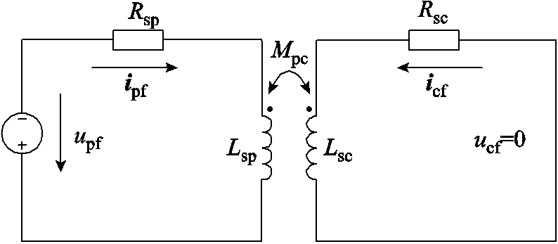
图5 电网电压跌落时无刷双馈发电机等效电路
Fig.5 BDFG equivalent circuit diagram under grid voltage drops
图5中,upf为突加反向电网电压,且upf =-kups,k为功率绕组电压跌落程度系数,k为1时表示并网点突加一个与原电网电压幅值相同的反向电压,即电网电压瞬时对称跌落至0 V,ips和ics表示电网故障产生的功率绕组和控制绕组动态电流,根据图5中故障电压的参数,代入式(2)~式(5),解得
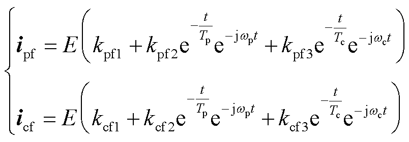 (11)
(11)
式中,E为与电网电压跌落程度有关的系数,E=upf/Ld,Ld = LspLsc-Mpc2;Tp为功率绕组的衰减时间常数,Tp = Ld/(RspLsc);Tc为控制绕组的衰减时间常数,Tc=Ld/(RscLsp);kpf1、kpf2和kpf3分别为功率绕组电流基频分量、直流分量和转速频率分量的系数;kcf1、kcf2和kcf3分别为控制绕组电流基频分量、直流分量和转速频率分量的系数,详细表达式为
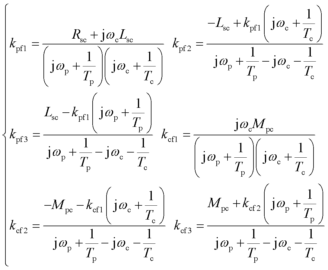 (12)
(12)
根据叠加原理,电网电压故障发生后,功率绕组和控制绕组电流的表达式为稳态分量与动态分量两部分线性叠加。
 (13)
(13)
至此,功率绕组同步坐标系下,电网电压瞬时对称跌落,无刷双馈发电机功率绕组和控制绕组的解析表达式已求解。可以看出,在电机参数确定的情况下,功率绕组和控制绕组电流的超调和振荡与电网电压的跌落程度、转速以及原电网电压矢量的相位(图3中电网电压与功率绕组A相的夹角φ)三者相关。若需要求解三相静止坐标系与dq旋转坐标系下的解析表达式,只需将复数形式进行相应旋转变换后即可求得。
对于实际运行的无刷双馈风力发电系统,电网电压跌落的程度和跌落时刻无法把控,且转速不会发生突变。而制造成型的电机,电机参数也无法改变。因此,只能从控制策略方面减小超调,加速收敛。状态反馈控制可改变电机的等效参数,优化电网故障下无刷双馈发电机的动态运行特性。
根据第1节的分析,电网电压瞬时对称跌落后,会使功率绕组和控制绕组的电流产生超调和振荡。为使发电系统不间断地运行,需要通过状态反馈控制减小系统的超调量,缩短振荡持续时间,尽量降低冲击损害。
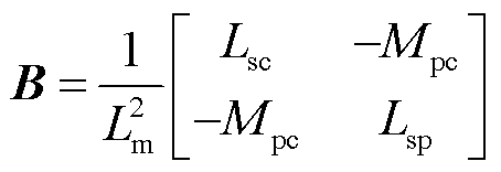
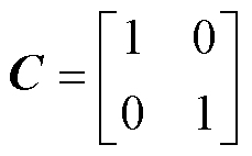
根据无刷双馈发电机动态数学模型式(2)~式(5),构造出式(14)所示无刷双馈风力发电机的状态空间方程式。该状态空间模型选取功率绕组电流ip和控制绕组电流ic为状态变量x,以功率绕组电压up和控制绕组电压uc为输入量u,再以ip和ic为输出量y,则有
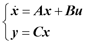 (14)
(14)
式中,A为系统矩阵;B为输入矩阵;C为输入矩阵。
 (15)
(15)

 (17)
(17)
 (18)
(18)
 (19)
(19)
可以证明上述系统可控,则可采用状态反馈使系统的特征根等于期望值。由于电机本身是稳定的,可使状态反馈系统矩阵的极点正比于原电机系统矩阵的极点,比例系数为δ(δ>1),这样可以保证系统能收敛到稳定值,且δ越大收敛速度越快。但过大则会导致系统对干扰信号过于敏感,从而影响系统的稳定性。
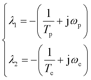
原系统矩阵A的特征根λ1和λ2为
 (20)
(20)
比较式(20)与式(11)可以发现,瞬态电流ipf和icf收敛速度与系统矩阵A特征根相关。进一步得到状态变量x的解为
 (21)
(21)
式(21)展开后与式(13)是相同的,x(0)即为式(9),表示跌落前绕组电流稳态值。结合式(12)可知功率绕组和控制绕组电流的峰值与收敛速度取决于系统矩阵A与输入矩阵B的参数,状态反馈控制策略恰好可改变两者的等效参数。构造无刷双馈风力发电机状态反馈控制系统结构如图6所示。
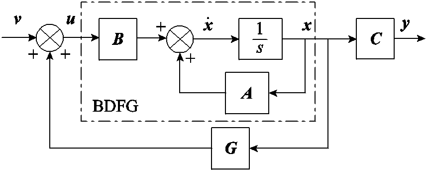
图6 无刷双馈风力发电机状态反馈控制系统结构
Fig.6 State feedback structure of BDFG
图6所示系统的动力学方程为
 (22)
(22)
式中,G为状态反馈增益矩阵;v为与原输入u同维的新输入,多输入多输出系统的状态反馈矩阵并不唯一,可设为
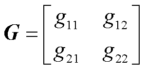 (23)
(23)
根据新输入v与原输入u的关系
 (24)
(24)
考虑到功率绕组直接连接无穷大电网,即新输入v中的upd和upq无法改变,只能改变ucd和ucq。因此,只需要对控制绕组电压加入状态反馈变量。
根据式(22)可知,在输入端加入状态反馈后,等效于新输入v与原输入u相同,而改变了原系统矩阵A,得到新系统矩阵为A+BG,由于加入状态反馈后系统极点是原系统极点的δ倍,根据行列式可解出反馈矩阵G的参数为
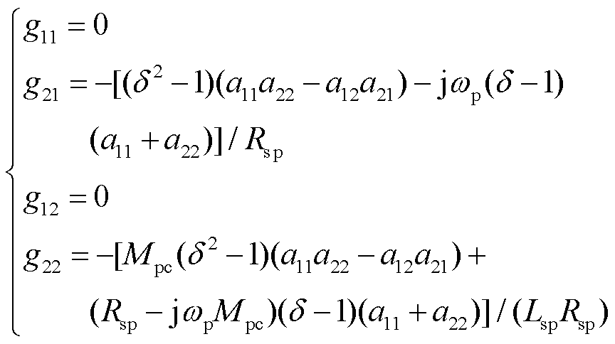 (25)
(25)
状态变量ip和ic由电流传感器采样获取,经坐标变换后,通过反馈矩阵G加入到控制绕组电压指令值,对发电机实行优化控制。引入状态反馈后系统矩阵极点往s平面大幅左移,则输出量的收敛速度较原系统会提升。无刷双馈风力发电机状态反馈控制策略如图7所示。
图7中,ucd0和ucq0表示电网电压故障发生时原控制绕组dq轴电流控制器的输出。电压瞬时跌落时,两个PI控制器停止工作,保持输出不变,然后叠加状态反馈控制补偿量Δucd和Δucq, 和
和 表示控制绕组电压指令值。
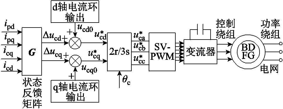
图7 无刷双馈发电机状态反馈控制策略
Fig.7 State feedback control strategy of BDFG
无刷双馈电机参数见表1,代入表1所示电机参数,原系统矩阵A的特征根为-0.727 8±1.154 8i和-0.773 2 ± 0.025 8i,其极点分布图如图8a所示;若取δ=2,新系统矩阵A+BG的特征根为:-3.531 7、-1.208 8和-0.841 7±0.700 3i,则极点分布如图8b所示。
表1 无刷双馈电机参数
Tab.1 Parameters of BDFG

参数数值 额定功率/W4 功率绕组极对数1 控制绕组极对数3 功率绕组额定电压/V380 控制绕组额定电压/V230 功率绕组额定电流/A6 控制绕组额定电流/A10 转速运行范围/(r/min)600~1 200 额定转矩/(N·m)55 功率绕组自感Lp/H0.665 9 控制绕组自感Lc/H0.189 8 转子绕组自感Lr/H0.844 2 功率/转子绕组互感Mpr/H0.654 7 控制/转子绕组互感Mcr/H0.184 1 功率绕组电阻Rp/Ω2.535 控制绕组电阻Rc/Ω2.327 转子绕组电阻Rr/Ω2.948
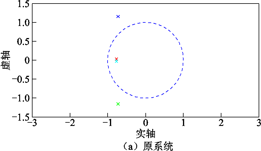
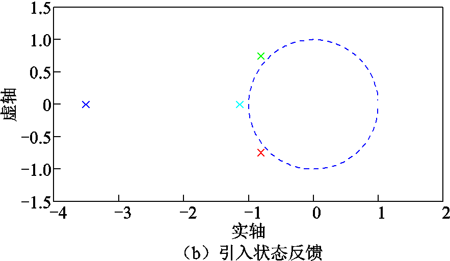
图8 原系统与引入状态反馈后系统矩阵的极点分布图
Fig.8 Pole distribution diagram of original system and the system with state feedback
从图8可以看出,由于引入状态反馈矩阵,理论上讲,原系统矩阵的极点应向左平移。但由于功率绕组直接与无穷大电网连接,故无法引入状态反馈量到功率绕组侧,从而新控制系统矩阵的极点往左移动的同时会有所偏移。由于往左大幅移动,从而会使无刷双馈发电机的物理量阶跃响应的收敛速度明显增大。
无刷双馈风力发电系统模拟实验平台如图9所示。左侧为电网模拟器,输出电压的幅值可以瞬时变化。中间为发电机组,原动机为三相异步变频调速电机,模拟风力机,右侧为发电机的控制系统。
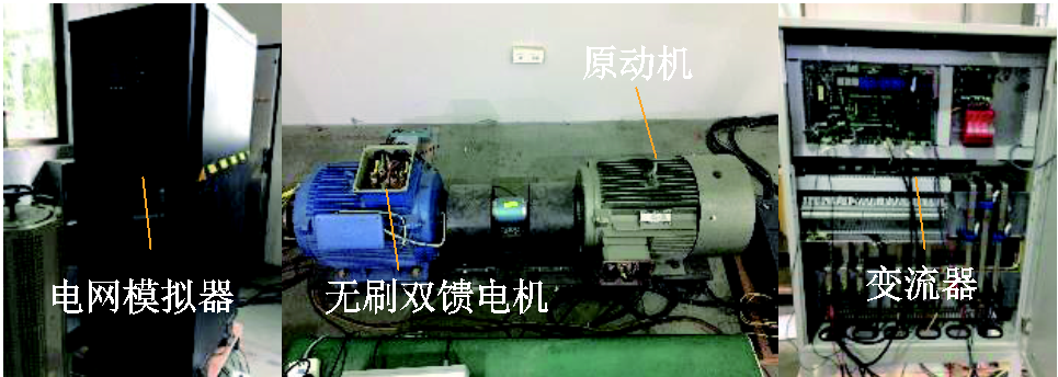
图9 无刷双馈风力发电系统实验平台
Fig.9 Experimental platform of BDFG system
实验的具体工况为:电网线电压的有效值为380V,峰值为540V,电网频率为工频50Hz。发电机的转速为900r/min,有功功率设定为4kW,与额定功率相同,无功功率设为0kvar,实验时长为20s。当t=2.1s时,电网电压瞬时跌落至原电网电压的20%,故障时长为3.1s;当t=5.2s时,电网电压开始恢复。
需要说明的是:电网模拟器设置相电压跌落速率为220V/ms,则线电压跌落速率为380V/ms,控制系统的算法周期为160ms。取功率绕组流向电网为正参考方向,且采用幅值相等的坐标变换。
电网电压瞬时对称跌落到20%时传统双闭环PI矢量控制与状态反馈控制策略的整个实验过程波形对比如图10和图11所示,包括电网线电压、功率绕组和控制绕组单相电流及其dq轴分量以及转速的波形。故障阶段功率绕组和控制绕组单相电流及其dq轴分量、电磁转矩以及功率绕组有功和无功功率的局部放大图如图12和图13所示。
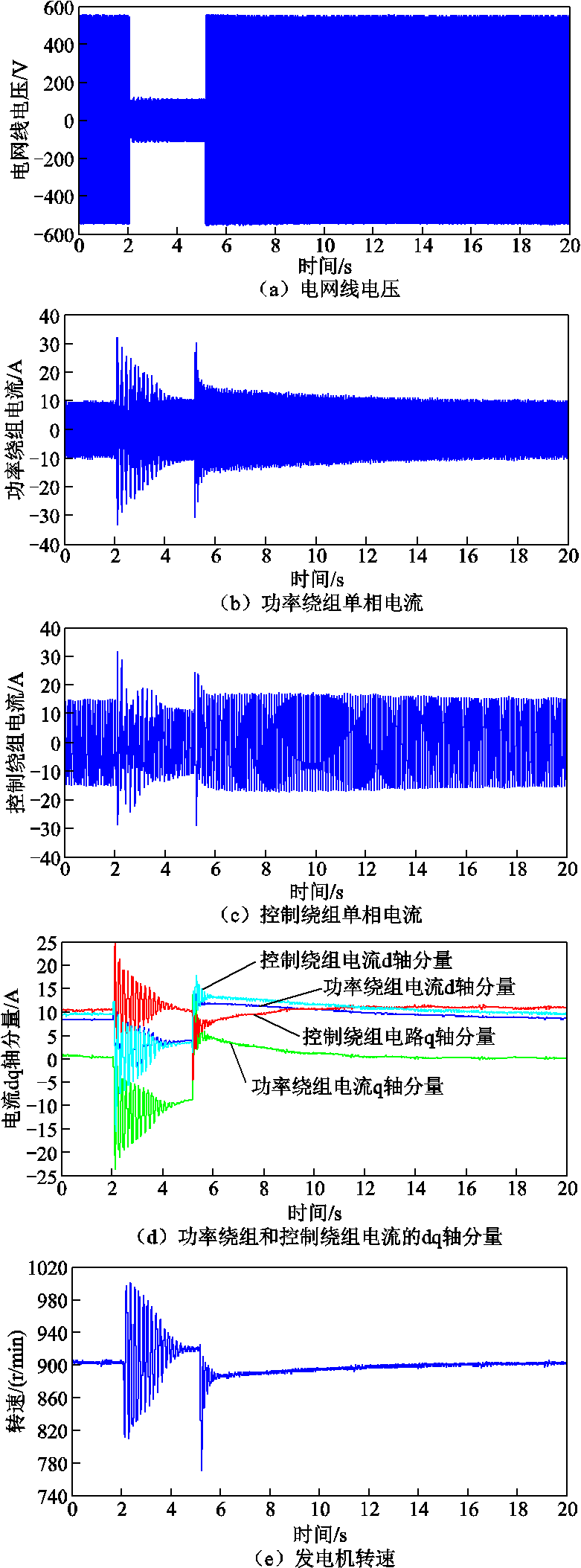
图10 电网电压跌落到20%传统控制实验全过程的波形
Fig.10 Experimental waveforms of the whole process of traditional control when the grid voltage drops to 20%
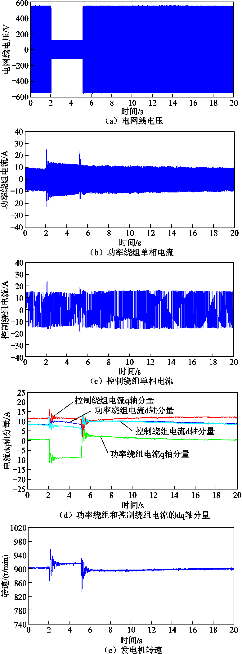
图11 电网电压跌落到20%状态反馈实验全过程的波形
Fig.11 Experimental waveforms of the whole process of state feedback control when the grid voltage drops to 20%
从图10所示传统控制策略实验全过程可以看出:发电机物理量的超调和振荡比较明显,且持续时间达到2.3s。观察图12所示发电机物理量的故障局部放大图,由图12a看出功率绕组电流的变化非常剧烈,其峰值从8.5A增加到32A,大约增加了3.7倍。图12b显示控制绕组电流幅值在电网电压下降之前为15A,突然上升至32A,增加到2.1倍额定值。同时图12c中icd与ipd同步变化,但是icq与ipq 变化趋势相反,且有ipd=icd,ipq=-0.8icq,表明功率绕组与控制绕组电流dq轴分量存在一定的比例关系。图12d中电磁转矩Te及图12e中功率绕组的有功和无功功率均相应地存在明显的波动。
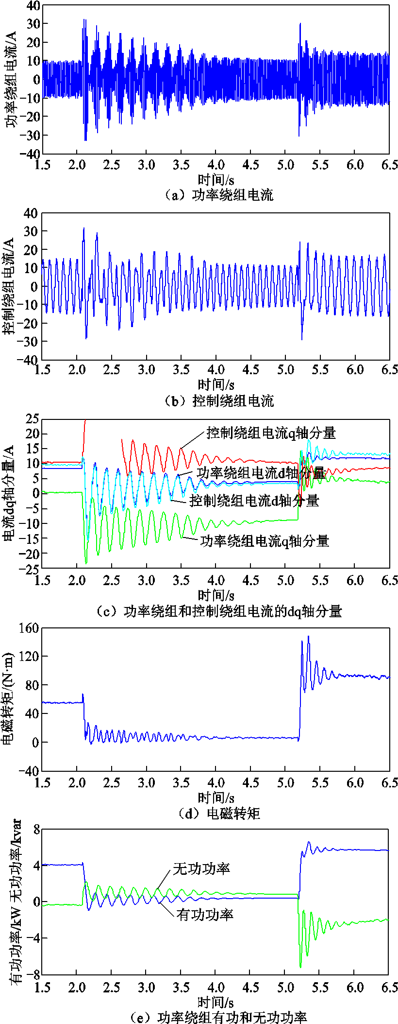
图12 电网电压跌落到20%传统控制故障局部放大图
Fig.12 Fault partial enlarged view of traditional control when the grid voltage drops to 20%
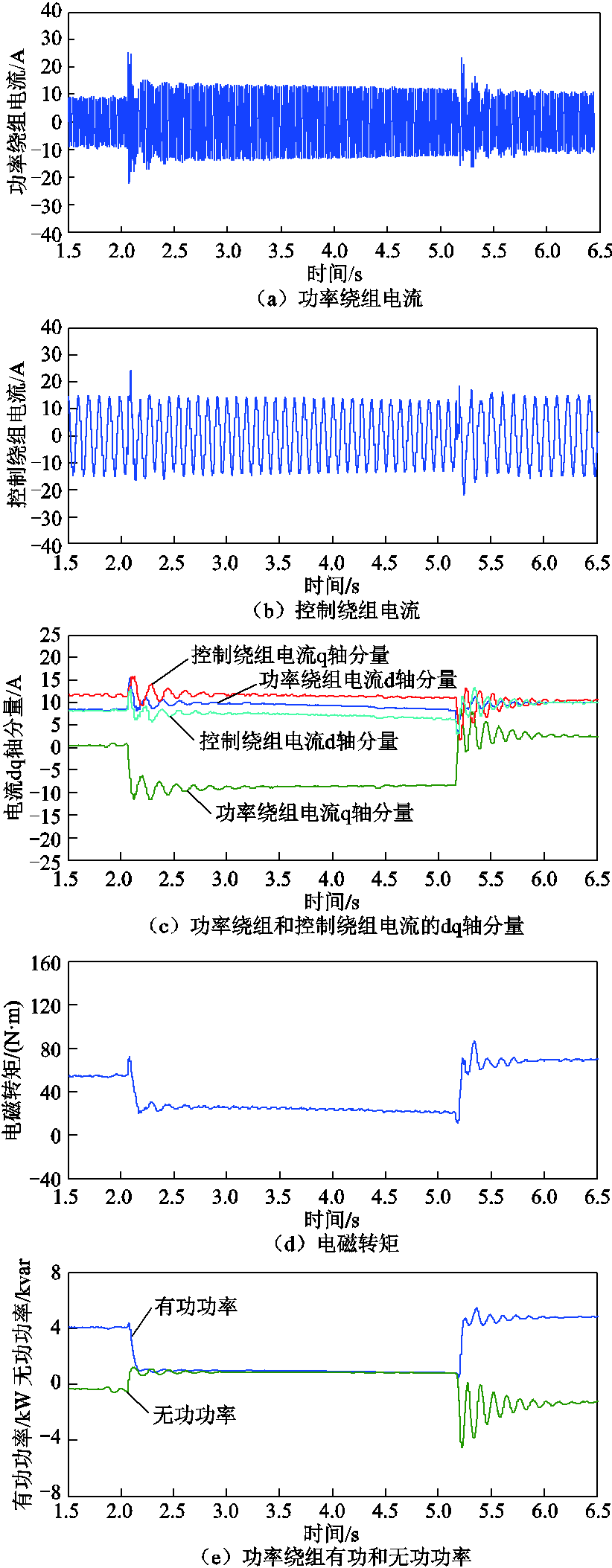
图13 电网电压跌落到20%状态反馈故障局部放大图
Fig.13 Fault partial enlarged view of state feedback when the grid voltage drops to 20%
总而言之,传统控制策略下系统在电网电压瞬时跌落和恢复时存在幅值很大且连续振荡环节,控制绕组峰值电流对于控制系统而言是非常不利的。因此,传统双闭环PI控制策略应对低电压穿越时,发电机的动态特性不符合要求,必须加以改进。
由于电力电子器件可短时承受2倍额定电流峰值,若逆变器的电流控制在2倍额定电流以内,则可以认为软件控制可行。
分析状态反馈控制策略时发电机物理量的波形,取δ为2。从图11可以看出,当电网电压瞬时跌落至20%时,系统的整体超调和振荡得到缓解。观察图13a中功率绕组电流的峰值从8.5A增加到25A,并在2个周期后稳定下来,其稳定值仅为15A。图13b中控制绕组额定电流15A,且最大振幅为25A,只有1.7倍额定值,不超过2倍。即变流器的电流不超过额定值的2倍,在IGBT承受范围内,其振荡在一个周期后消失,且稳态值与额定值几乎相同。图13c中ipd从8.5A增加到16A,icq从7.5A增加到12A。然后ipq从0A下降到-9A,此外,icd变化很小,有少许振荡,并保持在12.5A附近。四个电流均能够在1s内稳定下来。图13d中电磁转矩Te及图13e中功率绕组的有功和无功功率波动非常小。
对比图12和图13可以发现,在采用状态反馈法控制策略下,发电机物理量(功率绕组和控制绕组的dq轴分量和转速)的振幅和收敛时间优于原传统控制方法,但这些物理量收敛的稳态值稍微有所偏移,这与第2节的理论分析一致,且逆变器的电流峰值同样被控制在2倍额定值范围内,保证了电力电子器件的正常运行,从而验证了状态反馈法的正确性与可行性。
本文通过构建无刷双馈风力发电机的状态空间模型,提出一种状态反馈控制,改变了原系统矩阵的参数,本质上改变了特征根的负实部和输出量的瞬态系数,极点分布图显示新系统较原系统的极点大幅左移。从物理意义上来讲,相当于改变发电机等效电阻和电感,则进一步改变了功率绕组和控制绕组的衰减时间常数和瞬态电抗,从而当电网电压骤降时,此策略可以减小定子功率绕组和控制绕组衰减振荡电流的峰值,缩短收敛时间,优化系统的振荡和超调。
实验结果显示,状态反馈控制下发电机物理量的超调明显小于传统控制策略下对应的物理量的超调,振荡持续时间缩短,且满足功率器件的要求,整个控制系统的抗扰动能力得到增强。因此,状态反馈策略的有效性和实用性得到了验证。
参考文献
[1] 阚超豪, 鲍习昌, 金科, 等. 绕线转子无刷双馈电机多谐波联合起动过程中磁动势及性能分析[J]. 电工技术学报, 2020, 35(3): 481-493.
Kan Chaohao, Bao Xichang, Jin Ke, et al. Analysis of magnetomotive force and performance during starting process of wound-rotor brushless doubly-fed machine with combined multi-harmonic fields[J]. Transactions of China Electrotechnical Society, 2020, 35(3): 481-493.
[2] 李珍平, 王雪帆, 陈曦, 等. 无刷双馈电机的双馈与异步起动控制策略[J]. 电工技术学报, 2022, 37(14): 3576-3586.
Li Zhenping, Wang Xuefan, Chen Xi, et al. Doubly fed and asynchronous starting control strategies of brushless doubly fed machine[J]. Transactions of China Electrotechnical Society, 2022, 37(14): 3576-3586.
[3] 许利通, 程明, 魏新迟, 等. 考虑损耗的无刷双馈风力发电系统功率反馈法最大功率点跟踪控制[J]. 电工技术学报, 2020, 35(3): 472-480.
Xu Litong, Cheng Ming, Wei Xinchi, et al. Power signal feedback control of maximum power point tracking control for brushless doubly-fed wind power generation system considering loss[J]. Transactions of China Electrotechnical Society, 2020, 35(3): 472-480.
[4] 夏超英, 张耀华, 郭海宇. 无刷双馈电机反馈线性化控制方法[J]. 电工技术学报, 2020, 35(7): 1387-1397.
Xia Chaoying, Zhang Yaohua, Guo Haiyu. Feedback linearization control approach of brushless doubly fed machine[J]. Transactions of China Electrotechnical Society, 2020, 35(7): 1387-1397.
[5] Sadeghi R, Madani S M, Lipo T A, et al. Voltage-dip analysis of brushless doubly fed induction generator using reduced T-model[J]. IEEE Transactions on Industrial Electronics, 2019, 66(10): 7510-7519.
[6] Tohidi S, Oraee H, Zolghadri M R, et al. Analysis and enhancement of low-voltage ride-through capability of brushless doubly fed induction generator[J]. IEEE Transactions on Industrial Electronics, 2013, 60(3): 1146-1155.
[7] Long Teng, Shao Shiyi, Malliband P, et al. Crowbarless fault ride-through of the brushless doubly fed induction generator in a wind turbine under symmetrical voltage dips[J]. IEEE Transactions on Industrial Electronics, 2013, 60(7): 2833-2841.
[8] Shao Shiyi, Long Teng, Abdi E, et al. Symmetrical low voltage ride-through of the brushless doubly-fed induction generator[C]//IECON 2011-37th Annual Conference of the IEEE Industrial Electronics Society, Melbourne, VIC, Australia, 2011: 3209-3214.
[9] Huang Jiejie, Li Shenghu. Analytical expression for LVRT of BDFIG with enhanced current control to CW and reactive power support from GSC[J]. International Journal of Electrical Power & Energy Systems, 2018, 98: 243-255.
[10] Lu Min, Chen Yu, Zhang Debin, et al. Virtual synchronous control based on control winding orientation for brushless doubly fed induction generator (BDFIG) wind turbines under symmetrical grid faults[J]. Energies, 2019, 12(2): 319.
[11] Zhang Ailing, Chen Zhengfang, Gao Ruozhong, et al. Crowbarless symmetrical low-voltage ride through based on flux linkage tracking for brushless doubly fed induction generators[J]. IEEE Transactions on Industrial Electronics, 2020, 67(9): 7606-7616.
[12] 于淼, 李京霖. 基于状态反馈解耦控制的含DFIG电力系统低频振荡抑制研究[J]. 可再生能源, 2022, 40(2): 214-221.
Yu Miao, Li Jinglin. Research on low frequency oscillation suppression of power system with DFIG based on state feedback decoupling control[J]. Renewable Energy Resources, 2022, 40(2): 214-221.
[13] Debouza M, Errouissi R, Al-Durra A, et al. Design and implementation of a robust state-feedback control law for a grid-connected doubly fed induction generator wind turbine[C]//5th IET International Conference on Renewable Power Generation (RPG), London, UK, 2016: 1-6.
[14] Bhattarai R, Gurung N, Thakallapelli A, et al. Reduced-order state observer-based feedback control methodologies for doubly fed induction machine[J]. IEEE Transactions on Industry Applications, 2018, 54(3): 2845-2856.
[15] Apte A, Joshi V A, Mehta H, et al. Disturbance-observer-based sensorless control of PMSM using integral state feedback controller[J]. IEEE Transactions on Power Electronics, 2020, 35(6): 6082-6090.
[16] Yao Yu, Huang Yunkai, Peng Fei, et al. Position sensorless drive and online parameter estimation for surface-mounted PMSMs based on adaptive full-state feedback control[J]. IEEE Transactions on Power Electronics, 2020, 35(7): 7341-7355.
[17] Ouyang Jinxin, Tang Ting, Diao Yanbo, et al. Control method of doubly fed wind turbine for wind speed variation based on dynamic constraints of reactive power[J]. IET Renewable Power Generation, 2018, 12(9): 973-980.
[18] 徐伟, 陈俊杰, 刘毅, 等. 无刷双馈独立发电系统的改进无参数预测电流控制[J]. 电工技术学报, 2021, 36(19): 4002-4015.
Xu Wei, Chen Junjie, Liu Yi, et al. Improved nonparametric predictive current control for standalone brushless doubly-fed induction generators[J]. Transactions of China Electrotechnical Society, 2021, 36(19): 4002-4015.
[19] Sadeghi R, Madani S M, Ataei M. A new smooth synchronization of brushless doubly-fed induction generator by applying a proposed machine model[J]. IEEE Transactions on Sustainable Energy, 2018, 9(1): 371-380.
[20] Zhang Fengge, Zhu Liancheng, Jin Shi, et al. Controller strategy for open-winding brushless doubly fed wind power generator with common mode voltage elimination[J]. IEEE Transactions on Industrial Electronics, 2019, 66(2): 1098-1107.
[21] Hemanth Kumar M B, Saravanan B, Sanjeevikumar P, et al. Review on control techniques and methodologies for maximum power extraction from wind energy systems[J]. IET Renewable Power Generation, 2018, 12(14): 1609-1622.
[22] 王增平, 李菁, 郑涛, 等. 不同撬棒保护投入时刻下双馈风电机组短路电流计算分析[J]. 电力系统保护与控制, 2017, 45(5): 109-117.
Wang Zengping, Li Jing, Zheng Tao, et al. Calculation and analysis of three-phase short-circuit current of doubly fed wind turbine considering different crowbar protection insertion time[J]. Power System Protection and Control, 2017, 45(5): 109-117.
Abstract For the grid-connected wind power system with brushless doubly-fed generators (BDFG), the transient symmetrical drop of grid voltage is equivalent to a sudden impose of a reverse voltage source at the grid-connected point. As a matter of fact, there are some deficiencies in the current research on low voltage ride through of BDFG. To be specific, some literatures merely give theoretical research without optimization strategies, and in some other studies, the hardware equipment are installed to improve system performance, but it increased the system cost. What’s more, there are no comparative experiments carried out in the other works. On this basis, the dynamic operation characteristics of the BDFG under transient symmetrical voltage drop are deeply studied in this paper. Moreover, an optimal control strategy, i.e., state feedback control, is proposed to improve the transient operation characteristics of the control system.
Firstly, the simplified dynamic mathematical model of the BDFG after converting the rotor circuit is listed. Then, the steady-state current before the voltage drop as well as the transient current after the transient voltage drop are obtained. Afterwards, the current of the power winding (PW) and control winding (CW) after the transient voltage drop is solved by applying the superposition principle. It is observed from the results that the overshoots and oscillation time of the transient current are related to the generator parameters, the degree and phase of the voltage drop, as well as the rotor speed.
However, the degree and the phase of grid voltage drop cannot be controlled for the operating wind power system with BDFG. Moreover, the generator speed could not change suddenly. In addition, the parameters of the generator is fixed after been manufactured. To improve the operation characteristics of the control system, the state model is further constructed regarding PW and CW current as state variables. Then, the state variables are added to the input through the feedback matrix. Therefore, the parameters of the generator system matrix, i.e., the equivalent parameters of the generator are changed. As a result, the pole distribution diagram shows that the poles under the state feedback strategy are significantly shifted to the left compared with the traditional control model. Finally, a simulation case is conducted with the grid voltage drops to 20% under the rated working condition. The experimental waveform shows that the overshoot of the generator physical quantity with the proposed state feedback control is significantly smaller than which with the traditional control strategy. What’s more, the oscillation duration is shortened while the requirements of power devices are met. In summary, the anti-disturbance ability of the whole control system is enhanced with state feedback control method.
According to the experimental results, it is concluded that the parameters of the original system matrix of the BDFG is revised by introducing the state feedback control. Essentially, the negative real part of the eigenvalue and the transient coefficient of the output are changed. In the view of physical sense, it is equivalent to changing the equivalent resistance and inductance of the generator, which further changes the attenuation time constant and transient reactance of the PW and CW. Therefore, when the grid voltage drops suddenly, this strategy can effectively reduce the peak value of the oscillating current of the stator PW and CW. On this basis, the convergence time is shorten, and the oscillation as well as overshoot of the system are optimized. In conclusion, the effectiveness and practicability of the introduction of state feedback strategy have been verified.
Keyword:Brushless doubly fed generator, wind power generation, power grid voltage drops, oscillation and overshoot, state feedback
中图分类号:TM315
DOI:10.19595/j.cnki.1000-6753.tces.221139
东莞市引进创新科研团队计划资助项目(东科[2014] 109)。
收稿日期 2022-06-16
改稿日期 2022-07-31
聂鹏程 男,1987年生,博士研究生,研究方向为绕线转子无刷双馈并网与独立发电系统的控制。E-mail:niepengcheng2012@163.com(通信作者)
吴文辉 男,1988年生,工程师,研究方向为电力电子功率变换器和SiC器件的应用。E-mail:carefromstone@gmail.com
(编辑 赫蕾)