 (1)
(1)
摘要 机械应力会显著改变取向电工钢片的磁滞特性。Sablik-Jiles-Atherton(S-J-A)磁滞模型由于计算简单、物理含义明确,被广泛用于模拟机械应力作用下的磁滞特性,然而此模型存在模拟精度低的问题。为此,该文在现有S-J-A磁滞模型的基础上,考虑取向电工钢片本身的各向异性和由机械应力引起的各向异性,实现对无磁滞磁化强度表达式的修正;在此基础上,根据机械应力对取向电工钢片磁畴排列模式的影响,引入无磁滞磁化强度形状系数和钉扎系数对机械应力的依赖关系,提出一种改进的S-J-A磁滞模型;最后,以30QG120型取向电工钢片为例,应用所提改进模型模拟了不同机械应力下的磁滞回线,通过与实验测量和现有模型进行对比,验证了所提改进模型的准确性。
关键词:取向电工钢片 机械应力 Sablik-Jiles-Atherton磁滞模型 各向异性
由于晶粒取向电工钢片(Grain-Oriented Electrical Steel Sheets, GOES)的Goss织构,使得其在沿着轧制方向(Rolling Direction, RD)磁化时有着良好的磁特性,因此被广泛用于大功率电力变压器中[1-4]。然而,在对电力变压器铁心进行组装的过程中会对其施加应力,电力变压器运行过程中产生的热应变也会在铁心处产生机械应力[5],导致电工钢片的磁滞特性发生显著的变化。因此,提出一种能够准确模拟晶粒取向电工钢片机械应力作用下的磁滞模型,对电力变压器铁心的设计有着重要的意义。
目前,建立机械应力作用下的磁滞模型主要分为两种,其中第一种是基于磁畴的微观角度来建立,例如多尺度模型[1, 6-8]。多尺度模型是将施加到整个材料上的磁场和应力局部化,研究局部磁场和局部应力在单晶上的响应,利用均匀化法则将单晶的结果推广到多晶材料。由于需要对材料进行局部化和均匀化,涉及的参数较多,计算较为复杂。另外,多尺度模型仅仅给出了无滞回磁化强度的计算方法,通常需要与其他磁滞模型结合使用[7]。第二种是将应力因素耦合到现有的磁滞模型上,如Preisach磁滞模型[9-12]和Jiles-Atherton(J-A)磁滞模型[13-19]。其中,Preisach磁滞模型相比于从能量角度建立的J-A磁滞模型,不能清晰地描述应力对铁磁材料磁化特性的作用机制[20]。J-A磁滞模型是根据磁畴理论和畴壁钉扎原理提出的[21-22]。M. J. Sablik等在J-A磁滞模型的基础上,考虑了应力对材料磁性能的影响,在有效场中引入应力附加项,提出了Sablik-Jiles-Atherton(S-J-A)应力相关磁滞模型[23-24]。由于应用S-J-A磁滞模型时与实验数据之间存在较大差异[15],因此出现了许多改进模型。文献[25]通过引入一个新的磁畴耦合因子,分析了铁磁材料在拉应力下的磁滞特性,但该方法缺少压应力下的磁滞特性模拟以及相关实验验证。文献[16]考虑了不同应力下磁滞回线的不对称性,提出应力相关的磁致伸缩模型,并对S-J-A磁滞模型提出了相关的半解析改进,但该方法仅针对无取向电工钢片,缺少关于应力对取向电工钢片的磁滞特性影响的研究。A. Ramesh等对各向同性J-A磁滞模型进行了推广,将单轴和立方各向异性形式等不同形式的各向异性能考虑进J-A磁滞模型中,通过进一步考虑纹理的影响,对各向异性模型进行了扩展[26-27]。然而,A. Ramesh等的研究并没有考虑机械应力的影响,仅仅考虑了各向异性能对J-A磁滞模型的影响。
针对上述问题,本文基于原始S-J-A磁滞模型,在无滞回磁化强度中引入材料本身的各向异性能和由机械应力引起的各向异性能,并考虑模型相关参数对应力的依赖性,提出一种机械应力作用下取向电工钢片磁滞特性模拟方法。对比拟合结果和实验结果发现,拟合效果较好,验证了该方法的正确性和有效性。
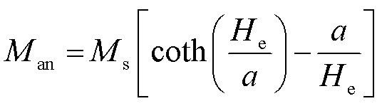
S-J-A磁滞模型是考虑磁机械耦合,基于热力学平衡建立的磁滞模型。各向同性材料的无滞回磁化强度Man表示为
(1)
其中
 (2)
(2)
 (3)
(3)
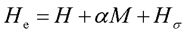
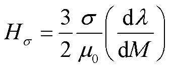
式中,Ms为饱和磁化强度;a为无滞回磁化曲线形状因子;He为有效磁场强度;H为外加磁场强度;M为磁化强度;Hs为由机械应力引起的附加磁场强度;a为磁畴内部耦合平均场参数;l为磁致伸缩系数;μ0为真空磁导率;s为外施机械应力,s的正负仅表示方向,s>0表示拉应力,s<0表示压应力。
S-J-A磁滞模型中通过泰勒级数展开给出磁致伸缩与磁化强度的关系[15]为
 (4)
(4)
式中, 、
、 、
、 、
、 为展开式系数,文献[15]给定了它们的值。
磁化过程的能量守恒方程为
 (5)
(5)
 (6)
(6)
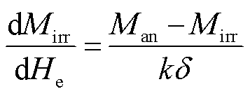 (7)
(7)
式中,k为钉扎参数;c为依赖于磁畴壁弯曲的可逆系数;Mrev为可逆磁化强度;Mirr为不可逆磁化强度;δ为方向系数,当dH/dt>0时,δ=1,当dH/dt<0时,δ=-1。
根据式(1)~式(7)可以推出S-J-A磁滞模型(正模型)为
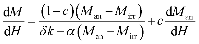 (8)
(8)
由于实际工程中,变压器等设备的激励都是电压,根据法拉第电磁感应定律可知,电压激励与磁感应强度有关,因此需要建立以磁感应强度B为输入,磁场强度H为输出的逆S-J-A磁滞模型。将dHe/dB= 1/m0+(a-1)dM/dB代入式(8)中,可以得到S-J-A逆模型为
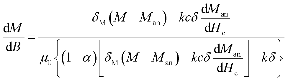 (9)
(9)
式中,δM是为了防止出现非物理解而引入的参数,有
 (10)
(10)
原始S-J-A磁滞模型的无滞回磁化强度用朗之万函数表示,仅适用于各向同性材料,当对GOES叠片磁滞回线进行建模时,结果会明显不准确[28]。由于取向电工钢片的晶体取向,其磁性表现出了强烈的各向异性特征[29],而各向异性能对外施应力有很强的依赖性,因此原始S-J-A磁滞模型不适用于模拟取向电工钢片在机械应力下的磁滞模型。同时,在工程应用中发现,S-J-A磁滞模型的磁致伸缩模型与实际情况有较大差异。此外,原始S-J-A磁滞模型没有考虑应力对相关参数的影响。针对以上问题,本文在原始S-J-A磁滞模型的基础上,在无滞回磁化强度中引入各向异性能作为附加项,磁致伸缩模型用磁化强度与应力的乘积表示,并考虑模型相关参数对应力的依赖性,从而模拟取向硅钢在机械应力条件下的磁滞特性。
当系统中存在各向异性能量时,系统的总能量E[30]可以表示为
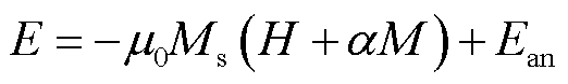 (11)
(11)
式中,Ean为各向异性能。在未加应力的情况下,其表达式[31]为
 (12)
(12)
式中, 、
、 和
和 为磁化矢量相对于三个晶轴的方向余弦;K0、K1和K2为各向异性常数,K0和K2可以忽略且并不会明显影响精度[32]。
取向电工钢片二维模型如图1所示。在取向电工钢片平面取两个磁矩m1和m2,由于各向异性能的对称性,只需要分析m1和m2从0°~180°的磁性能。因此,两个磁矩m1和m2的各向异性能分别为
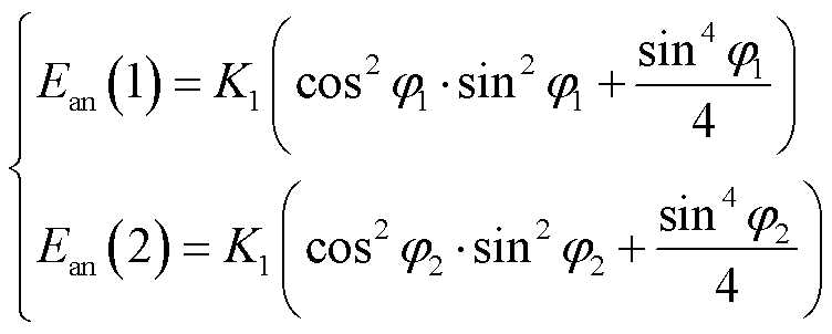 (13)
(13)
其中
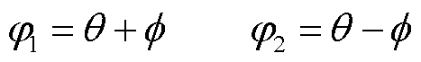
式中,q为外加磁场与磁矩之间的角度;f为RD与外加磁场之间的角度。
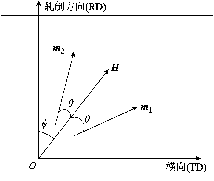
图1 取向电工钢片二维模型
Fig.1 Two dimensional model of GO silicon steel
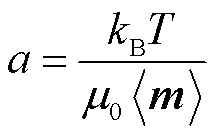
在没有应力的情况下,各向异性材料的无滞回磁化强度[30]可以表示为
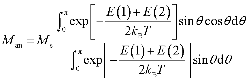 (14)
(14)
式中,kB为玻耳兹曼常数;T为系统的温度;kBT为系统的热能,该热能可由参数a=nkBT/(m0Ms)计算得到,其中,n为单位体积内的有效磁畴个数。磁矩m1和m2的总能量E(1)和E(2)可以分别表示为
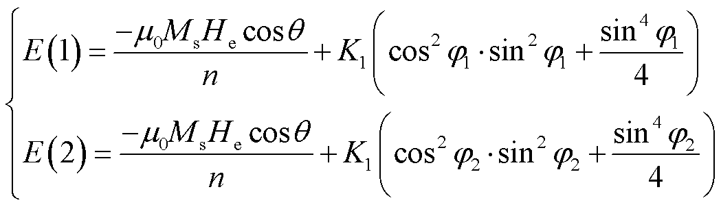 (15)
(15)
将式(15)代入式(14)中,则无滞回磁化强度可表示为
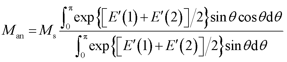 (16)
(16)
其中
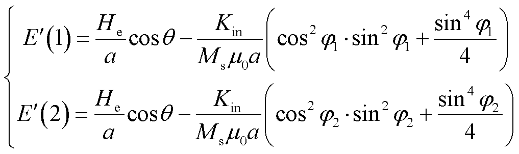 (17)
(17)
式中,Kin为材料本身的平均各向异性能密度。
在原始S-J-A磁滞模型中,应力只通过对有效场的影响来改变磁滞回线的形状,本文认为应力对有效场的贡献并没有原始模型的那么大,在Hs中引入应力因子gs来表示应力的实际贡献[16]。同时,由于取向电工硅钢片强烈的各向异性,应力还将通过对各向异性能的影响来改变其磁性能,因此需要将机械应力引起的平均各向异性能密度作为附加项引入到总平均各向异性能密度中。则无滞回磁化强度中的能量项变为
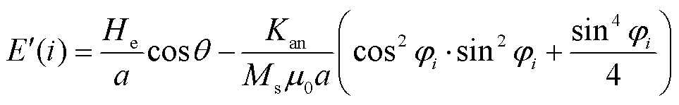 (18)
(18)
式中,Kan为总平均各向异性能密度,Kan=Kin+Ks,其中,Ks为机械应力引起的平均各向异性能密度;i=1, 2。将式(18)代入到式(16)中即为考虑应力条件下无滞回磁化强度的表达式。
M. E. Kuruzar和B. D. Cullity的实验结果表明,磁致伸缩应变是关于磁化强度的偶函数[33]。基本磁致伸缩模型认为磁致伸缩系数λ与压应力和拉应力之间是线性关系。然而,实验表明λ对拉应力和压力是非均匀依赖的[34],即磁致伸缩在拉应力和压应力下表现出不对称性,因此本文将磁致伸缩看作是磁化强度M和外施机械应力s共同作用的结果,采用式(19)表示磁致伸缩[16]。
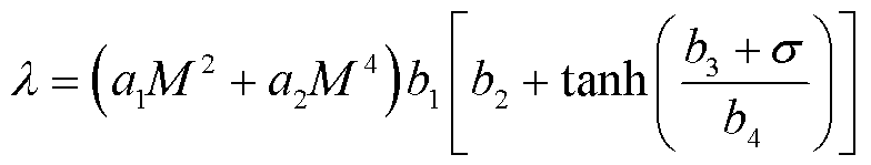 (19)
(19)
式中,a1、a2、b1、b2、b3及b4为拟合参数,通过磁致伸缩实验数据拟合得到;a1M2+a2M4项表示磁致伸缩与磁化强度的关系;而 则表示应力对磁致伸缩的影响。
原始S-J-A磁滞模型中钉扎系数k是单位磁化的能量损耗,取决于脱离钉扎位置所需要的平均钉扎能量。根据文献[35],S-J-A磁滞模型中的钉扎系数k与磁化强度M存在非线性关系。由于外施应力改变了材料内部的状态和钉扎位置,文献[36]认为k还与外施机械应力有关。因此,钉扎系数k是磁化强度M和外施机械应力s共同作用的结果,则k可以表示[37]为
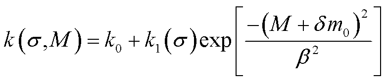 (20)
(20)
式中,m0和b 为常数;k1(s)为应力对钉扎系数的影响;k0为没有应力作用下的钉扎系数。
值得注意的是,相关文献中认为仅参数k是对机械应力有依赖性的,而参数a及其他参数不受外施机械应力的影响。但事实上,无滞回磁化形状参数a是由内部磁畴的形状大小和排列方式共同决定的[22,38],即参数a与铁磁材料的微观结构密切相关。而机械应力会改变晶粒取向电工钢片磁畴的排列方式[5,39],导致其磁畴大小及密度发生变化。所以参数a对机械应力同样具有依赖性。因此,本文根据实验结果将a定义为一个关于应力的分段函数,表示为
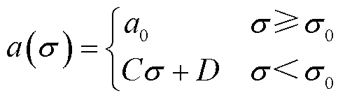 (21)
(21)
式中,a0为没有应力作用时无滞回磁化形状参数的值;C和D为实验数据拟合得到的系数; 为常数,表示当施加的机械应力达到时a不再是一个常数,会随着应力的增加而变化。
采用BROCKHAUS-MPG200/MST500软磁材料测试系统测量30QG120取向电工钢片的磁特性,实验测量平台如图2所示。该系统与应力装置配合使用,转动应力旋钮,便可在待测样片上施加一定数值的机械应力。该实验系统采用了全数字化的数据采集系统,可实现H与B的并行存储,从而保证H和B的同步测量,避免了由相位差而引起的测量误差。此外,该系统使用了能够自动调节激励电源的输出电压的自适应负反馈算法,保证了磁特性相关数据测量的准确性。同时,该平台利用干涉仪和反光片测量样片的磁致伸缩特性。测量方法及结果符合国际电工委员会(International Electrotechnical Commission, IEC)标准IEC 60404-2[40]。利用实测的一次电流及二次侧空载电压,计算磁场强度H(t)和磁感应强度B(t)分别为
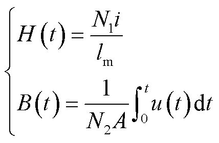 (22)
(22)
式中,N1为一次线圈的匝数;i为一次线圈励磁电流;lm为等效磁路长度;A为取向电工钢片的等效截面积;N2为二次线圈匝数;u为二次线圈电压。
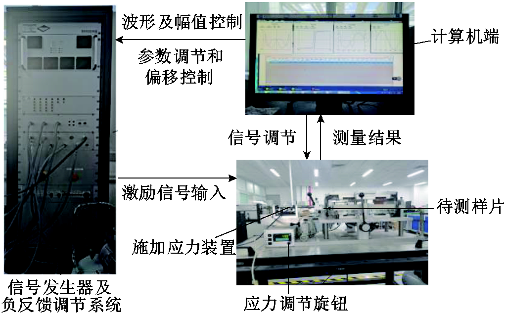
图2 实验测量平台
Fig.2 Experimental measurement platform
为减小测量误差,本文选取两片同生产批次、具有相同型号和规格的取向电工钢片分别进行拉应力和压应力作用下的磁滞特性测量实验,且实验过程中所施加的应力和磁场与轧制方向平行。对样品施加的应力均是从小向大递增进行施加,以进一步减小实验测量误差。选取的取向硅钢片样品参数见表1。
表1 取向硅钢片样品参数
Tab.1 The parameters of GO silicon steel sample
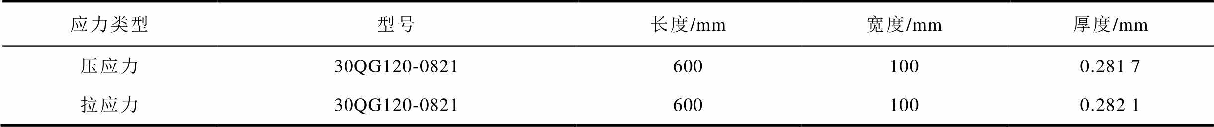
应力类型型号长度/mm宽度/mm厚度/mm 压应力30QG120-08216001000.281 7 拉应力30QG120-08216001000.282 1
改进模型的参数识别由三个步骤组成。
1)在零应力下拟合改进S-J-A磁滞模型参数。在不考虑应力作用的情况下(即Hs=0时),本文采用粒子群算法[41]得到改进S-J-A磁滞模型的初始参数Ms、a、a、k、c和Kin,见表2。
表2 不加应力下改进S-J-A磁滞模型参数
Tab.2 The paramaeters of Sablik-Jiles-Atherton model without stress
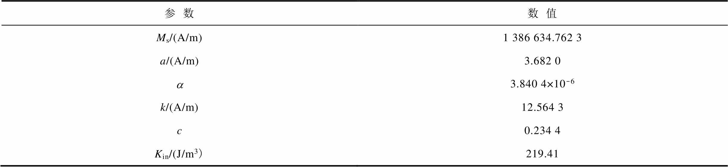
参数数值 Ms/(A/m)1 386 634.762 3 a/(A/m)3.682 0 a3.840 4×10⁻⁶ k/(A/m)12.564 3 c0.234 4 Kin/(J/m3)219.41
2)拟合磁致伸缩模型参数。通过拟合s = -7.14 MPa时的磁致伸缩曲线得到式(19)中的a1和a2,拟合曲线如图3所示。然后,用每个应力水平下测得的磁致伸缩峰值λpk来确定式(19)中参数b1~b4的值,拟合曲线如图4所示。表3给出了拟合得到的磁致伸缩模型相关参数的值。将表3中的参数值代入到式(19)中得到总的磁致伸缩l,将拟合结果与实验结果进行对比如图5所示。
3)应力相关参数的拟合。根据零应力下改进S-J-A磁滞模型参数和磁致伸缩相关参数,通过实验测量数据拟合确定每个应力作用下应力相关参数的值,其中认为m0和b的值仅与是拉应力还是压应力有关,与应力大小无关,其值见表4。
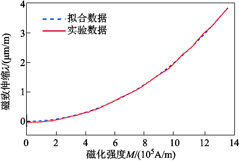
图3 s =-7.14 MPa时的磁致伸缩曲线
Fig.3 Magnetostrictive curve when s =-7.14 MPa
表3 磁致伸缩模型参数
Tab.3 Valus of the parameters of the magnetostriction model
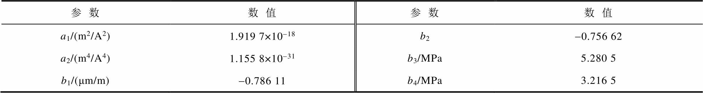
参数数值参数数值 a1/(m2/A2)1.919 7×10-18b2-0.756 62 a2/(m4/A4)1.155 8×10-31b3/MPa5.280 5 b1/(μm/m)-0.786 11b4/MPa3.216 5
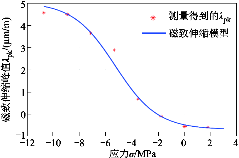
图4 磁致伸缩峰值lpk与应力s的关系
Fig.4 Relationship between magnetostrictive peak lpk and s
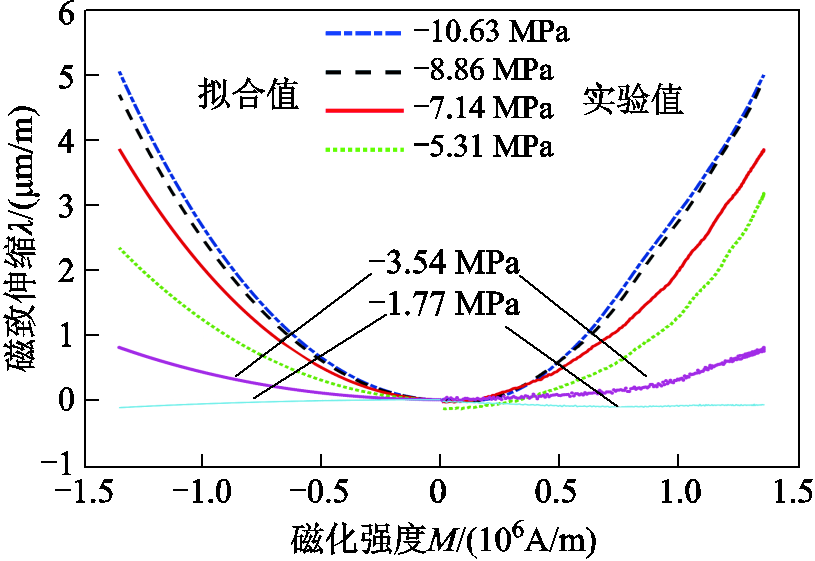
图5 测量与拟合磁致伸缩
Fig.5 Measuring and fitting magnetostriction
表4 应力相关参数
Tab.4 Relevant parameters under stress
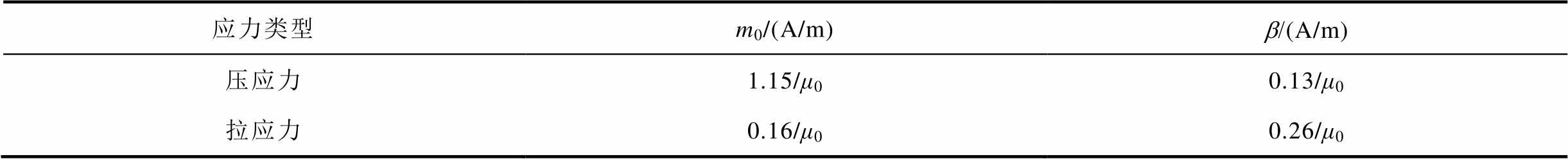
应力类型m0/(A/m)b/(A/m) 压应力1.15/μ00.13/μ0 拉应力0.16/μ00.26/μ0
为了验证本文提出的改进S-J-A磁滞模型的准确性和合理性,将本文方法与原始S-J-A磁滞模型进行对比分析,基于3.2节参数识别得到改进模型参数,对不同应力下磁感应强度峰值Bm=1.7 T条件下的磁滞回线进行模拟,仿真曲线与实测曲线对比如图6、图7所示。从图6和图7所示的结果可以看出,改进模型的磁滞回线拟合结果明显优于原始模型,验证了本文所提模型的有效性。此外还可以看出,取向电工钢片的矫顽力Hc随机械应力的增大而增大,且相比于拉应力,矫顽力对压应力更敏感;取向电工钢片的剩磁Br随机械应力的增大而减小。
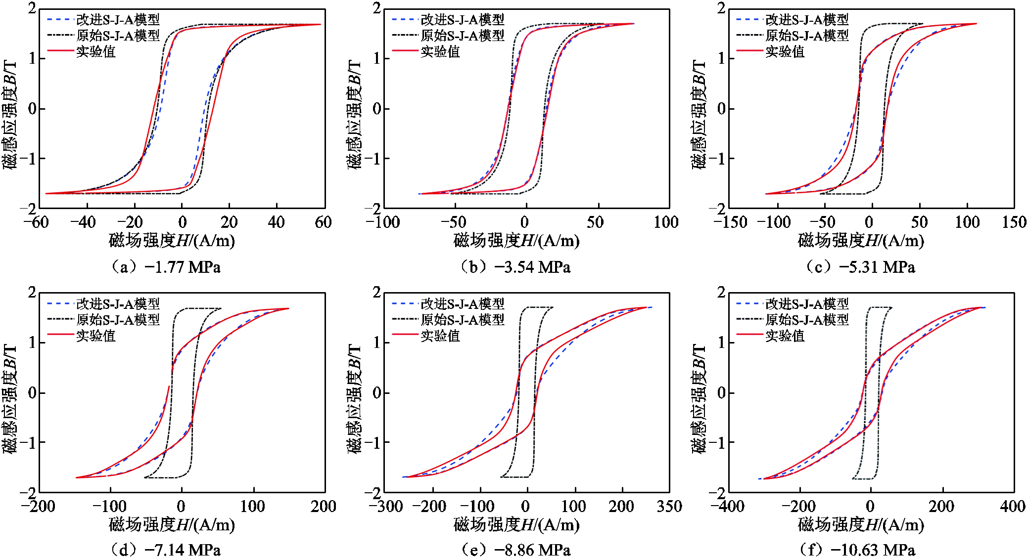
图6 不同压应力下Bm=1.7 T的仿真结果
Fig.6 Simulation results of Bm=1.7 T under different compressive stresses

图7 不同拉应力下Bm=1.7 T的仿真结果
Fig.7 Simulation results of Bm=1.7 T under different tensile stresses
为了定量分析改进模型的计算精度,选用方均根误差(Root Mean Square Error, RMSE)作为模型拟合度优劣的评价标准,其计算公式为
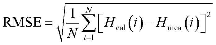 (23)
(23)
式中,Hcal为计算值;Hmea为测量值;N为实验数据的个数。RMSE的值越小则表示模型拟合度越高。两个模型计算不同压应力和拉应力下磁滞回线拟合结果的方均根误差见表5、表6。
从表5和表6的结果可以看出,本文提出的改进S-J-A磁滞模型在拉应力和较小的压应力条件下,拟合效果较好,方均根误差不超过3 A/m,证明了本文模型的准确性和合理性。当压应力数值大于7.14 MPa时其误差会变大,最大达到了8.21 A/m,但整体拟合情况可以接受。误差增大的原因在于,与各向异性能变化无关的现象也会导致磁滞回线形状发生改变,而模型参数变化并没有考虑相关现象。此外,导致误差变大的另外一个原因是,在较大压应力作用下,实验测量的精度会下降。
表5 压应力下不同模型的方均根误差比较
Tab.5 Comparison of RMSE of different models under compressive stress
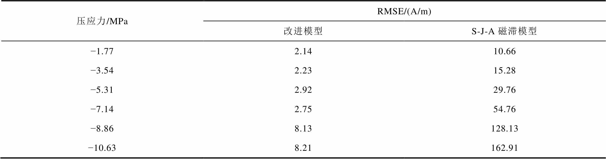
压应力/MPaRMSE/(A/m) 改进模型S-J-A磁滞模型 −1.772.1410.66 −3.542.2315.28 −5.312.9229.76 −7.142.7554.76 −8.868.13128.13 −10.638.21162.91
表6 拉应力下不同模型的方均根误差比较
Tab.6 Comparison of RMSE of different models under tensile stress
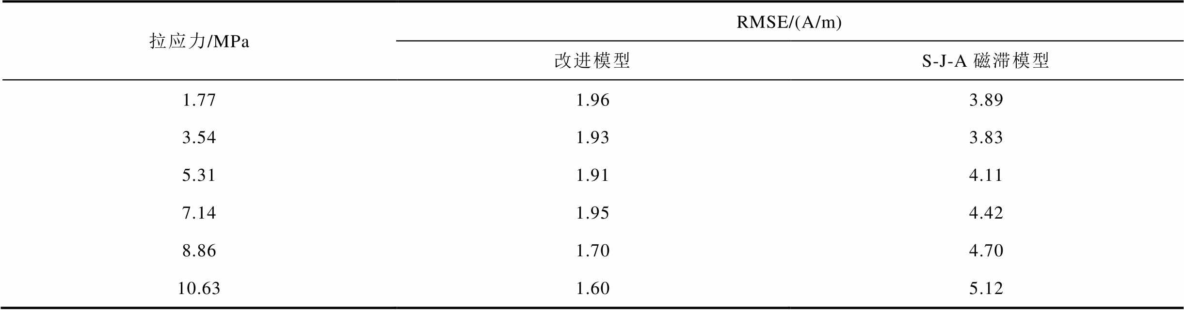
拉应力/MPaRMSE/(A/m) 改进模型S-J-A磁滞模型 1.771.963.89 3.541.933.83 5.311.914.11 7.141.954.42 8.861.704.70 10.631.605.12
将本文方法与原始S-J-A磁滞模型进行对比发现,原始模型的方均根误差随着压应力的增大而增大,在s =-10.63 MPa时方均根误差达到了162.91 A/m,误差过大难以接受。在拉应力的条件下,原始模型的方均根误差同样大于相同拉应力条件下本文所提方法得到的结果。通过以上分析可知,本文方法得到的拟合精度高于原始S-J-A磁滞模型,证明了本文所提方法的优越性。
为了进一步说明所提方法的精确性,表7列出方均根误差占最大磁场强度的百分比,其计算公式为
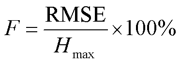 (24)
(24)
式中,Hmax为最大磁场强度。
表7 不同机械应力下不同模型的方均根误差占最大磁场强度的百分比
Tab.7 Percentage of RMSE of different models in the maximum magnetic field strength under different mechanical stresses
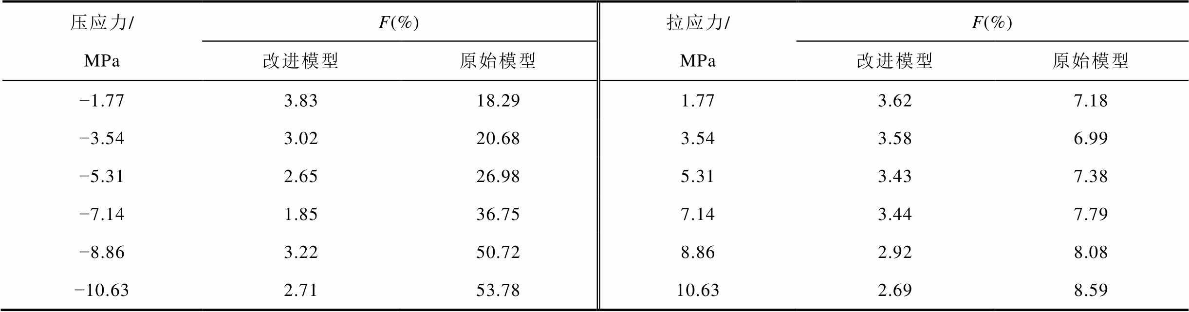
压应力/MPaF(%)拉应力/MPaF(%) 改进模型原始模型改进模型原始模型 −1.773.8318.291.773.627.18 −3.543.0220.683.543.586.99 −5.312.6526.985.313.437.38 −7.141.8536.757.143.447.79 −8.863.2250.728.862.928.08 −10.632.7153.7810.632.698.59
从表7的结果可以看出,本文提出的改进S-J-A磁滞模型在不同的机械应力条件下,其方均根误差占最大磁场的百分比均不超过4%。而原始模型的方均根误差占最大磁场的百分比的最大值已经达到了53.78%,误差过大而难以接受,进一步说明了本文所提方法的准确性。
应力所致平均各向异性能密度Ks随应力变化的关系如图8所示,可以看出Ks随着压应力的增加先减小,当压应力继续增大时Ks开始增加,这种现象就是Villari反转的表现形式之一;但拉应力并没有改变其平均各向异性能密度。
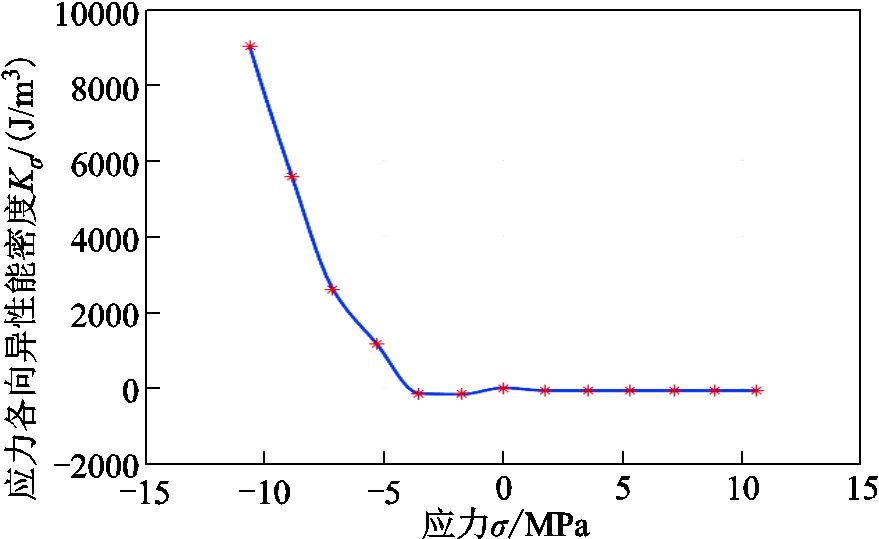
图8 平均应力所致各向异性能量密度Kσ与应力之间的关系
Fig.8 relationship between anisotropic energy density Kσcaused by stress
钉扎应力相关参数k1与应力的关系如图9a所示,可知k1与拉应力呈正比关系。当压应力数值小于3.54 MPa时,k1随压应力的增加而增大,但当压应力的值大于3.54 MPa时,尽管k1仍然跟随压应力的增大线性增加,但其斜率变大。这是因为当压应力增加到一定数值时,取向电工钢片中的磁畴排列会从零应力模式变为应力Ⅰ型[5,39],这种磁畴排列形式的转换,增加了单位体积内磁畴的密度,从而增加了钉扎点的平均密度[38],导致k1会发生较大变化。
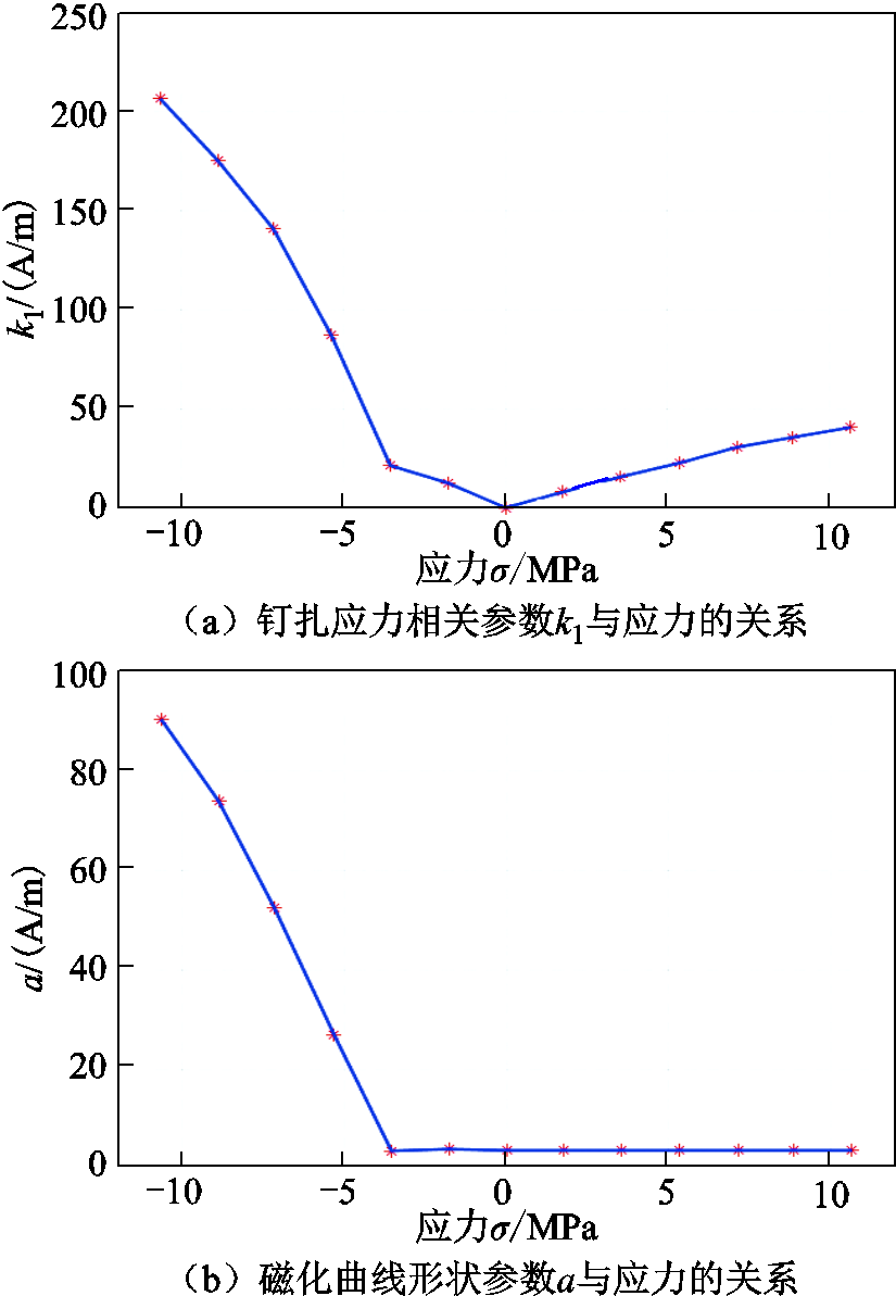
图9 k1和a与应力的关系
Fig.9 Relationship between k1 and a and stress
图9b为无滞后磁化曲线形状参数a与应力之间的关系,在拉应力和较小的压应力(小于3.54 MPa)作用下,a的值基本上无变化。但当压应力数值大于3.54 MPa时,a随着压应力的增加而增加。这种变化同样是由于磁畴排列方式的转变导致的。无滞回磁化曲线形状参数a也被称为有效磁畴密度的模型参数(有效磁畴包括一个磁化方向的磁矩)[22,38],定义为
 (25)
(25)
式中, 为有效磁畴的平均磁矩大小。当磁畴排列从零应力模式转变到应力Ⅰ型时,有效磁畴的密度会变大,导致有效磁畴的平均磁矩变小,所以a会在某个压应力后突然变大。
1)本文基于原始S-J-A磁滞模型,在无滞回磁化强度中引入应力所致平均各向异性能密度,并考虑模型相关参数对应力的依赖性,建立了机械应力作用下的取向电工钢片磁滞模型。
2)本文基于建立的改进S-J-A磁滞模型对30QG120型取向电工钢片在不同应力条件下的磁滞特性进行了模拟,并与实验结果进行了对比,计算得到方均根误差最大为8.21 A/m,验证了本文改进模型的有效性和准确性。并将改进模型与原始S-J-A磁滞模型关于电工钢片的模拟结果进行对比分析。结果表明,改进模型的模拟精度更高,证明了其优越性。
3)提取不同机械应力下的模型参数,结果表明S-J-A磁滞模型中应力所致平均各向异性能密度Ks、钉扎应力相关系数k1及无滞回磁化曲线形状参数a对机械应力有着明显的依赖性,并且这些参数对压应力和拉应力的依赖性不同。因此,在模拟取向电工钢片在不同机械应力下的磁滞特性需要考虑相关参数的应力依赖性。
4)在后续工作中,可考虑将本文提出的模型与有限元相数值计算方法相结合,进行变压器的相关分析。
参考文献
[1] Hubert O, Daniel L. Multiscale modeling of the magneto-mechanical behavior of grain-oriented silicon steels[J]. Journal of Magnetism and Magnetic Materials, 2008, 320(7): 1412-1422.
[2] Anderson P I, Moses A J, Stanbury H J. Assessment of the stress sensitivity of magnetostriction in grain-oriented silicon steel[J]. IEEE Transactions on Magnetics, 2007, 43(8): 3467-3476.
[3] 赵志刚, 徐曼, 胡鑫剑. 基于改进损耗分离模型的铁磁材料损耗特性研究[J]. 电工技术学报, 2021, 36(13): 2782-2790.
Zhao Zhigang, Xu Man, Hu Xinjian. Research on magnetic losses characteristics of ferromagnetic materials based on improvement loss separation model[J]. Transactions of China Electrotechnical Society, 2021, 36(13): 2782-2790.
[4] 陈彬, 秦小彬, 万妮娜, 等. 基于R-L型分数阶导数与损耗统计理论的铁磁材料高频损耗计算方法[J]. 电工技术学报, 2022, 37(2): 299-310.
Chen Bin, Qin Xiaobin, Wan Nina, et al. Calculation method of high-frequency loss of ferromagnetic materials based on R-L type fractional derivative and loss statistical theory[J]. Transactions of China Electrotechnical Society, 2022, 37(2): 299-310.
[5] Dias M B S, Landgraf F J G. Compressive stress effects on magnetic properties of uncoated grain oriented electrical steel[J]. Journal of Magnetism and Magnetic Materials, 2020, 504: 166566.
[6] Zhao Wei, Wang Shuting, Xie Xianda, et al. A simplified multiscale magneto-mechanical model for magnetic materials[J]. Journal of Magnetism and Magnetic Materials, 2021, 526: 167695.
[7] Daniel L, Rekik M, Hubert O. A multiscale model for magneto-elastic behaviour including hysteresis effects[J]. Archive of Applied Mechanics, 2014, 84(9): 1307-1323.
[8] Daniel L, Hubert O, Buiron N, et al. Reversible magneto-elastic behavior: a multiscale approach[J]. Journal of the Mechanics and Physics of Solids, 2008, 56(3): 1018-1042.
[9] Bergqvist A, Engdahl G. A stress-dependent magnetic Preisach hysteresis model[J]. IEEE Transactions on Magnetics, 1991, 27(6): 4796-4798.
[10] 李伊玲, 李琳, 刘任. 机械应力作用下电工钢片静态磁滞特性模拟方法研究[J]. 中国电力, 2020, 53(10): 10-18.
Li Yiling, Li Lin, Liu Ren. Modeling methods of static hysteresis characteristics of electrical steel sheets under stress[J]. Electric Power, 2020, 53(10): 10-18.
[11] Ktena A. Vector Preisach modeling of magnetic materials under stress[J]. Journal of Physics: Conference Series, 2015, 585: 012001.
[12] 赵小军, 刘小娜, 肖帆, 等. 基于Preisach模型的取向硅钢片直流偏磁磁滞及损耗特性模拟[J]. 电工技术学报, 2020, 35(9): 1849-1857.
Zhao Xiaojun, Liu Xiaona, Xiao Fan, et al. Hysteretic and loss modeling of silicon steel sheet under the DC biased magnetization based on the preisach model[J]. Transactions of China Electrotechnical Society, 2020, 35(9): 1849-1857.
[13] Sablik M J, Jiles D C. A model for hysteresis in magnetostriction[J]. Journal of Applied Physics, 1988, 64(10): 5402-5404.
[14] Sablik M J, Kwun H, Burkhardt G L, et al. Model for the effect of tensile and compressive stress on ferromagnetic hysteresis[J]. Journal of Applied Physics, 1987, 61(8): 3799-3801.
[15] Jiles D C. Theory of the magnetomechanical effect[J]. Journal of Physics D: Applied Physics, 1995, 28(8): 1537-1546.
[16] Singh D, Martin F, Rasilo P, et al. Magnetomechanical model for hysteresis in electrical steel sheet[J]. IEEE Transactions on Magnetics, 2016, 52(11): 1-9.
[17] 贲彤, 陈芳媛, 陈龙, 等. 考虑力-磁耦合效应的无取向电工钢片磁致伸缩模型的改进[J]. 中国电机工程学报, 2021, 41(15): 5361-5371.
Ben Tong, Chen Fangyuan, Chen Long, et al. An improved magnetostrictive model of non-oriented electrical steel sheet considering force-magnetic coupling effect[J]. Proceedings of the CSEE, 2021, 41(15): 5361-5371.
[18] Liu Qingyou, Luo Xu, Zhu Haiyan, et al. Modeling plastic deformation effect on the hysteresis loops of ferromagnetic materials based on modified Jiles-Atherton model[J]. Acta Physica Sinica, 2017, 66(10): 107501.
[19] 祝丽花, 李晶晶, 朱建国. 服役条件下取向硅钢磁致伸缩模型的研究[J]. 电工技术学报, 2020, 35(19): 4131-4138.
Zhu Lihua, Li Jingjing, Zhu Jianguo. Research on magnetostrictive model for oriented silicon steel under service conditions[J]. Transactions of China Electrotechnical Society, 2020, 35(19): 4131-4138.
[20] Kumar A, Arockiarajan A. Evolution of nonlinear magneto-elastic constitutive laws in ferromagnetic materials: a comprehensive review[J]. Journal of Magnetism and Magnetic Materials, 2022, 546: 168821.
[21] Jiles D C, Thoelke J B, Devine M K. Numerical determination of hysteresis parameters for the modeling of magnetic properties using the theory of ferromagnetic hysteresis[J]. IEEE Transactions on Magnetics, 1992, 28(1): 27-35.
[22] Jiles D C, Atherton D L. Theory of ferromagnetic hysteresis (invited)[J]. Journal of Applied Physics, 1984, 55(6): 2115-2120.
[23] Sablik M J, Rubin S W, Riley L A, et al. A model for hysteretic magnetic properties under the application of noncoaxial stress and field[J]. Journal of Applied Physics, 1993, 74(1): 480-488.
[24] Sablik M J. A model for asymmetry in magnetic property behavior under tensile and compressive stress in steel[J]. IEEE Transactions on Magnetics, 1997, 33(5): 3958-3960.
[25] Ikhlef M, Bendjerad A, Boukhtache S, et al. Refined approach in Jiles-Atherton model for ferromagnetic sheet under the tensile stress[J]. Journal of Superconductivity and Novel Magnetism, 2021, 34(1): 227-234.
[26] Ramesh A, Jiles D C, Bi Y. Generalization of hysteresis modeling to anisotropic materials[J]. Journal of Applied Physics, 1997, 81(8): 5585-5587.
[27] Jiles D C, Ramesh A, Shi Y, et al. Application of the anisotropic extension of the theory of hysteresis to the magnetization curves of crystalline and textured magnetic materials[J]. IEEE Transactions on Magnetics, 1997, 33(5): 3961-3963.
[28] Zirka S E, Moroz Y I, Moses A J, et al. Static and dynamic hysteresis models for studying transformer transients[J]. IEEE Transactions on Power Delivery, 2011, 26(4): 2352-2362.
[29] Shin S, Schaefer R, DeCooman B C. Anisotropic magnetic properties and domain structure in Fe-3%Si (110) steel sheet[J]. Journal of Applied Physics, 2011, 109(7): 07A307.
[30] Ramesh A, Jiles D C, Roderick J M. A model of anisotropic anhysteretic magnetization[J]. IEEE Transactions on Magnetics, 1996, 32(5): 4234-4236.
[31] Jiles D C, Ramesh A, Shi Y, et al. Application of the anisotropic extension of the theory of hysteresis to the magnetization curves of crystalline and textured magnetic materials[C]// 1997 IEEE International Magnetics Conference (INTERMAG), Orleans, LA, USA, 1997: FD-08.
[32] Celasco M, Mazzetti P. Saturation approach law for grain-oriented polycrystalline magnetic materials[J]. IEEE Transactions on Magnetics, 1969, 5(3): 372-378.
[33] Kuruzar M E, Cullity B D. The magnetostriction of iron under tensile and compressive stress[J]. International Journal of Magnetism, 1971, 1(4): 323-325.
[34] Li Jianwei, Xu Minqiang. Modified Jiles-Atherton- Sablik model for asymmetry in magnetomechanical effect under tensile and compressive stress[J]. Journal of Applied Physics, 2011, 110(6): 063918.
[35] Wlodarski Z. The Jiles-Atherton model with variable pinning parameter[J]. IEEE Transactions on Magnetics, 2003, 39(4): 1990-1992.
[36] Lo C C H, Lee S J, Li L, et al. Modeling of stress effects on magnetic hysteresis and Barkhausen emission using an integrated hysteretic-stochastic model[C]//2002 IEEE International Magnetics Conference (INTERMAG), Amsterdam, Netherlands, 2002: FS07.
[37] Sai Ram B, Baghel A P S, Kulkarni S V, et al. A frequency-dependent scalar magneto-elastic hysteresis model derived using multi-scale and Jiles–Atherton approaches[J]. IEEE Transactions on Magnetics, 2020, 56(3): 1-5.
[38] Jiles D C, Atherton D L. Theory of ferromagnetic hysteresis[J]. Journal of Magnetism and Magnetic Materials, 1986, 61(1-2): 48-60.
[39] Perevertov O, Schäfer R. Magnetic properties and magnetic domain structure of grain-oriented Fe-3%Si steel under compression[J]. Materials Research Express, 2016, 3(9): 096103.
[40] Alatawneh N, Rahman T, Hussain S, et al. Accuracy of time domain extension formulae of core losses in non-oriented electrical steel laminations under non-sinusoidal excitation[J]. IET Electric Power Applications, 2017, 11(6): 1131-1139.
[41] 曹祎, 王路, 雷民, 等. 基于改进粒子群算法的电流互感器J-A模型参数辨识[J]. 电测与仪表, 2021, 58(5): 70-77.
Cao Yi, Wang Lu, Lei Min, et al. Parameter identification for J-a hysteresis model of current transformer based on improved particle swarm optimization algorithm[J]. Electrical Measurement & Instrumentation, 2021, 58(5): 70-77.
Abstract Grain-oriented electrical steel sheets are widely used in high power transformers because of their good magnetic properties in the rolling direction. However, the core of transformer will be affected by mechanical stress during assembly and operation, resulting in significant changes in the hysteresis characteristics of electrical steel sheets. The Sablik-Jiles-Atherton (S-J-A) hysteresis model is widely used to simulate the hysteresis characteristics under mechanical stress because of its simple calculation and clear physical meaning. Due to the crystal orientation of the grain-oriented electrical steel sheets, its magnetic properties exhibit strong anisotropic characteristics, and the anisotropic energy has a strong dependence on the applied external stress. The original S-J-A model doesn’t consider the influence of anisotropic energy, which makes the S-J-A model significantly inaccurate in modeling the hysteresis return of grain-oriented electrical steel sheets laminations. To solve these problems, this paper proposes an improved S-J-A model that takes into account the anisotropic energy and the stress dependence of the model parameters.
In this paper, the anisotropic energy is considered in the anhysteretic magnetization., including the anisotropic energy of the material itself as well as the anisotropic energy due to mechanical stress. At the same time, the magnetostriction and pinning coefficient k are regarded as the result of the joint action of the magnetization M and the applied mechanical stress s. In addition, in the relevant literature, only the parameter k is considered to be dependent on the mechanical stress, and other parameters are not affected by the mechanical stress. In the actual simulation of the model, it is found that the shape parameter of anhysteretic magnetization a is also dependent on the mechanical stress, so an improved s-j-a model is obtained.
The simulation results show that the improved S-J-A hysteresis model fits better under tensile stress and smaller compressive stress, and the mean square error does not exceed 3A/m, which proves the accuracy and reasonableness of the model in this paper. When the compressive stress is greater than 7.14 MPa, the error becomes larger, reaching a maximum of 8.21 A/m, but the overall fit is acceptable. Comparing this method with the original S-J-A hysteresis model, it is found that the mean square error of the original model increases with the increase of compressive stress, reaching 162.91 A/m at s = -10.63 MPa, which is too large to be acceptable. Under the condition of tensile stress, the mean square error of the original model is also larger than that of the proposed method under the same tensile stress. Through the above analysis, it can be seen that the fitting accuracy obtained by this method is higher than that of the original S-J-A hysteresis model, which proves the superiority of the proposed method.
The following conclusions are obtained from the simulation of the hysteresis line under stress: (1) The simulation results of the improved model and the original S-J-A model for electrical steel sheets are compared and analyzed. The results show that the simulation accuracy of the improved model is higher, which proves its superiority. (2) The model parameters under different mechanical stresses are extracted, and the results show that the average anisotropic energy density Kan, the pinning coefficient k and the shape parameter of anhysteretic magnetization a in the S-J-A model have obvious dependence on the mechanical stresses, and these parameters have different dependence on the compressive and tensile stresses.
keywords:Grain-oriented electrical steel sheets, mechanical stress, Sablik-Jiles-Atherton hysteresis model, anisotropy
中图分类号:TM271
DOI:10.19595/j.cnki.1000-6753.tces.220971
国家重点研发计划课题(2021YFB2401703)和国家自然科学基金(52177005)资助项目。
收稿日期 2022-05-30
改稿日期 2022-06-20
朱育莹 女,1997年生,硕士研究生,研究方向为软磁材料磁弹性耦合模拟。E-mail:z_yy1997@163.com(通信作者)
李 琳 男,1962年生,教授,博士生导师,研究方向为电磁场理论及应用与先进输变电技术。E-mail:lilin@ncepu.edu.cn
(编辑 李冰)