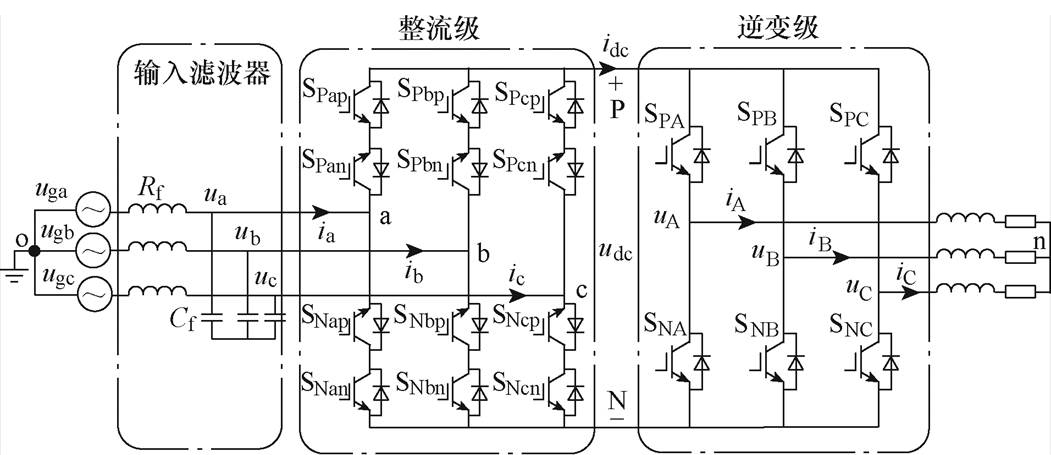
图1 间接矩阵变换器
Fig.1 Indirect matrix converter
摘要 现有的间接矩阵变换器共模电压抑制策略大都聚焦于降低峰值而缺少对减小高频共模电压幅值的研究。基于有效矢量作用下的共模幅值和正负特性,该文提出一种大幅度减小间接矩阵变换器高频共模电压的新型调制策略,该策略的共模电压在一个输入扇区内正负方向不发生变化:整流级调制选择相邻两个有效矢量,逆变级调制在输入1、3、5扇区选择输出共模电压方向始终为正的有效电压矢量V2、V4、V6;在输入2、4、6扇区选择输出共模电压方向始终为负的有效电压矢量V1、V3、V5。通过减小共模电压在一个载波周期内的跳变次数和变化幅值,可以大幅度减小高频共模电压。最后,通过仿真和实验结果验证了该方法的有效性。
关键词:间接矩阵变换器(IMC) 高频共模电压 正负特性 调制策略
间接矩阵变换器(Indirect Matrix Converter, IMC)由于其输出电压波形可控、输入输出电流正弦、输入功率因数可控、集成度高、能量密度高[1-2]等优点成为极具潜力的新一代交流变流器[3-4]。IMC运行时会在输出端产生高频高幅值的共模电压(Common Mode Voltage, CMV),从而产生漏电流,高频漏电流会产生极大的电磁干扰(Electromagnetic Interference, EMI)问题,影响系统的可靠运行[5-6]。当IMC驱动电机时,其共模电压会促使电机绝缘老化,增大轴承间的机械磨损,减少轴承寿命[7-8]。因此,抑制IMC共模电压高频分量具有重要的工程应用意义。
通过在系统共模路径上加入有源或无源滤波器等硬件补偿装置[9-12]可以有效地实现对高频共模电压的抑制,但这种方法会增加系统成本和控制的复杂度且应用场合受限,因此,通过优化调制策略而不需要增加额外硬件的软件方法来抑制高频共模电压幅值更具优势。
文献[13-14]通过消除逆变级零矢量的调制策略抑制了共模电压峰值。文献[15]提出分别适用于电压传输比范围0.577~0.866和0~0.5的两种共模峰值抑制调制方法。文献[16]通过在整流级用3个矢量合成可变的直流母线电压,在逆变级用两个有效矢量合成输出电压的调制方法降低了共模电压。文献[17-18]基于两种不同的开路矢量应用原则抑制了共模电压和共模电流。文献[19]在整流级和逆变级均使用3个有效矢量,在降低共模电压的同时还提高了输出质量,减小了输出电流谐波。文献[20]基于有效电流矢量,提出一种降低共模电压的间断脉冲宽度调制(Discontinuous Pulse Width Modulation, DPWM)方法。
以上调制方法均将IMC共模电压峰值进行了不同程度的抑制,通过实验波形的快速傅里叶变换(Fast Fourier Transistor, FFT)分析可知,这些抑制共模电压峰值的调制策略在一定程度上只能有效抑制某一频段的高频共模电压。文献[21]通过调节模块化多电平逆变器三相载波初始相位,改变三相各高频成分之间的相位关系,达到了抑制高频共模电压的目的。文献[22]提出一种抑制两电平逆变器高频共模电压的矢量调制策略,其在理想条件下的共模电压在一个开关周期可维持不变。文献[23]提出一种使两电平逆变器共模电压幅值和频率最小化的混合空间矢量脉宽调制(Space Vector Pulse Width Modulation, SVPWM),将每个逆变器扇区细分成三个区域,每个区域使用不同的调制方法,该方法降低了共模电压的高频分量,但大大增加了调制难度。文献[24-25]的特定谐波消除法可消除变换器特定频率的共模电压,但是求解超越方程组的运算十分复杂。文献[26]对IMC输出电压进行三重傅里叶建模,获得了高频共模分量与电压传输比及零矢量作用时间的数学关系,为IMC高频共模分量的精准数学建模提供了思路和方法。
本文提出一种减小IMC高频共模电压的新型调制策略,在将共模电压峰值减小42.3%的基础上,大幅度减小所有高频段的共模电压幅值。该新型调制策略将整流级调制分为6个扇区,根据每个输入扇区内各有效矢量作用下的共模电压幅值的正负特性,在每个输入扇区用两个相邻有效电流矢量合成参考输入电流矢量。逆变级调制分为6个扇区,根据输入扇区选择输出共模电压正负在一个输入扇区不发生变化的有效电压矢量。当输入电流位于1、3、5扇区时,逆变级采用输出共模电压方向都为正的3个有效电压矢量;当输入电流位于2、4、6扇区时,逆变级采用输出共模电压方向都为负的3个有效电压矢量。该新型调制策略的共模电压正负方向在一个输入扇区内不发生改变,减小了共模电压变化次数和变化幅值,从而大幅度减小高频共模电压。通过仿真和实验对比分析了几种同样将共模电压峰值抑制了42.3%的典型调制方法的高频共模频谱,验证了该调制策略高频共模抑制的有效性。
间接矩阵变换器如图1所示,IMC由电流源型整流器(Current Source Rectifier, CSR)与电压源型逆变器(Voltage Source Inverter, VSI)组成,中间母线上无直流储能元件,输入侧设置输入滤波器,滤除主电路开关器件产生的高次谐波,使网测电流正弦化。
为分析方便,定义1为开关管导通,0为关断。根据IMC输入端不能短路和输出端不能开路的原则,IMC整流级有九种开关状态,对应9个电流矢量,包括6个有效电流矢量Iab、Iac、Ibc、Iba、Ica、Icb及3个零电流矢量Iaa、Ibb、Icc;逆变级有八种开关状态,对应8个电压矢量,包括6个有效电压矢量V1(100)、V2(110)、V3(010)、V4(011)、V5(001)、V6(101)和两个零电压矢量V0(000)、V7(111)。
图1 间接矩阵变换器
Fig.1 Indirect matrix converter
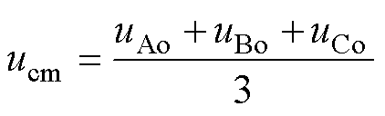
共模电压ucm是指负载中性点n与电源地点o之间的电压,如图1所示,当IMC驱动三相对称负载时,共模电压ucm为
 (1)
(1)
式中,uAo、uBo、uCo分别为三相输出A、B、C点到o点之间的电压。从文献[13]可知,当IMC使用零矢量时共模电压峰值最大,等于输入相电压峰值Vin,为降低共模电压峰值,本文只分析有效矢量下的共模特性。以整流级采用有效电流矢量Iab,逆变级采用有效电压矢量V1为例,IMC有效矢量Iab、V1作用下的等效电路如图2所示。三相输出电压uAo、uBo和uCo分别等于IMC输入电压ua、ub和ub,如图2中虚线所示,其输出共模电压为输入线电压的1/3,即ubc/3。

图2 IMC有效矢量Iab、V1作用下的等效电路
Fig.2 IMC equivalent circuit under active vectors Iab, V1
为分析方便,IMC整流级划分为6个扇区,各扇区下输入线电压的1/3如图3所示。当输入功率因数为1时,IMC各有效矢量作用下的CMV峰值及正负见表1。由表1和图3可知,IMC的共模电压在不同有效矢量的作用下具有以下特性:
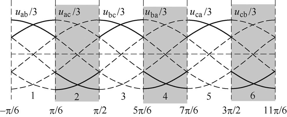
图3 整流级扇区划分及输入电压
Fig.3 Sector divided for rectifier stage and input voltage
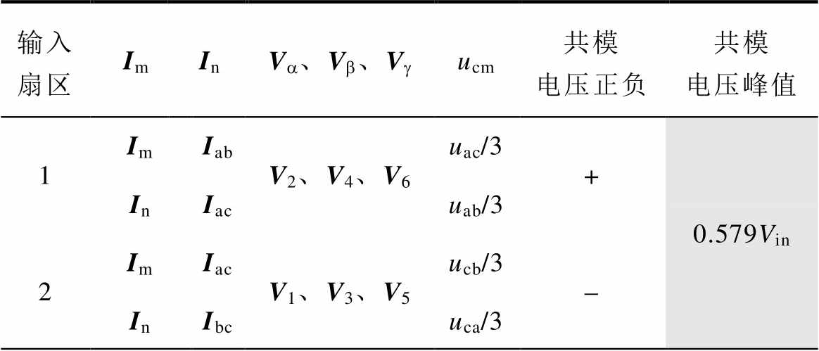
表1 IMC各有效矢量对应的共模电压
Tab.1 The CMV corresponding to each vector of the IMC

kinIm, InV1, V3, V5V2, V4, V6 ucm幅值正负ucm幅值正负 1Iabubc/3+uac/3+ Iacucb/3-uab/3 3Ibcuca/3+uba/3 Ibauac/3-ubc/3 5Icauab/3+ucb/3 Icbuba/3-uca/3 2Iacucb/3-uab/3+ Ibcuca/3uba/3- 4Ibauac/3ubc/3+ Icauab/3ucb/3- 6Icbuba/3uca/3+ Iabubc/3uac/3-
(1)整流级1、3、5扇区,在两个相邻有效电流矢量Im、In作用下,逆变级奇数有效电压矢量作用下的共模电压具有幅值相同但方向正负变化的特性。逆变级偶数有效电压矢量作用下的共模电压具有方向均为正但幅值不同的特性。以整流级第1扇区选择Iab和Iac为例,奇数有效电压矢量作用下的共模电压为ubc/3和ucb/3,幅值相同,但方向相反;偶数有效电压矢量作用下的共模电压为uab/3和uac/3,幅值不同,但方向都为正。
(2)整流级2、4、6扇区,在两个相邻有效电流矢量Im、In作用下,逆变级偶数有效电压矢量作用下的共模电压具有幅值相同但方向正负变化的特性。逆变级奇数有效电压矢量作用下的共模电压具有方向均为负但幅值不同的特性。以整流级第2扇区选择Iac和Ibc为例,偶数有效电压矢量作用下的共模电压为uab/3和uba/3,幅值相同,但方向相反;奇数有效电压矢量作用下的共模电压为ucb/3和uca/3,幅值不同,但方向都为负。
根据第1节IMC各有效矢量作用下的共模电压幅值和正负特性分析,本文提出一种大幅度减小高频共模电压的调制策略,该策略下的共模电压正负方向在一个输入扇区下不发生改变,其整流级和逆变级的调制原理分别如图4和图5所示。
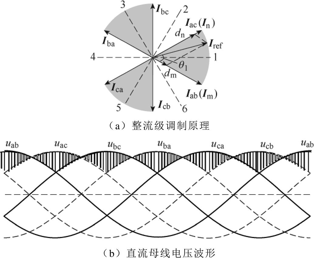
图4 整流级调制原理及直流母线电压波形
Fig.4 Rectifier stage modulation and the DC-bus waveforms
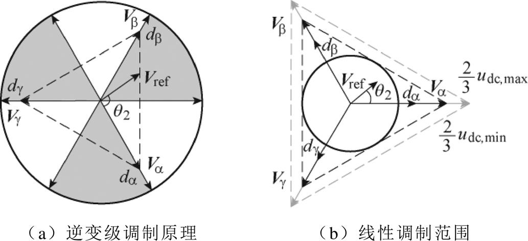
图5 逆变级调制原理及线性调制范围
Fig.5 Inverter stage modulation and the linear modulation range
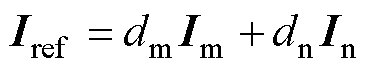
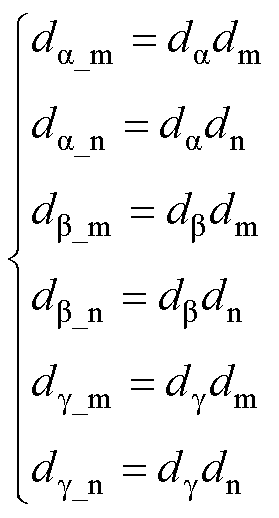
本文所提策略的整流级调制在每个输入扇区使用两个相邻有效电流矢量Im、In合成参考电流矢量Iref,如图4a所示,参考电流矢量Iref可表示为
 (2)
(2)
其中
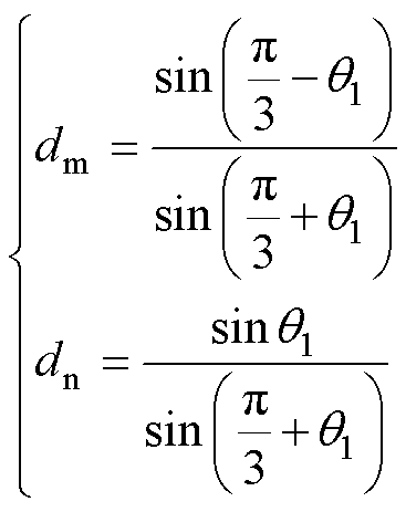 (3)
(3)
式中,q1为Iref与Im的夹角;dm、dn分别为有效电流矢量Im、In的占空比。
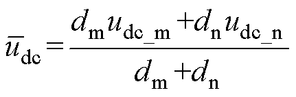
直流母线电压波形如图4b所示,一个载波周期内直流母线电压平均值 可表示为
可表示为
 (4)
(4)
式中,udc_m、udc_n分别为Im、In作用时的直流母线电压。以整流级第1扇区为例,可得直流母线电压的大小及范围分别为
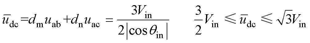 (5)
(5)
式中,cosqin=max(|cosqa|, |cosqb|, |cosqc|),qa、qb、qc为三相输入电流的相位。
逆变级根据不同整流级扇区选择3个有效电压矢量Va、Vb、Vg 合成参考电压矢量Vref。当整流级位于第1、3、5扇区时,选择输出共模电压幅值都为正的3个有效电压矢量V2、V4、V6;当整流级位于第2、4、6扇区时,选择输出共模电压幅值都为负的3个有效电压矢量V1、V3、V5,如图5a所示。参考电压矢量Vref可表示为
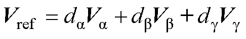 (6)
(6)
其中
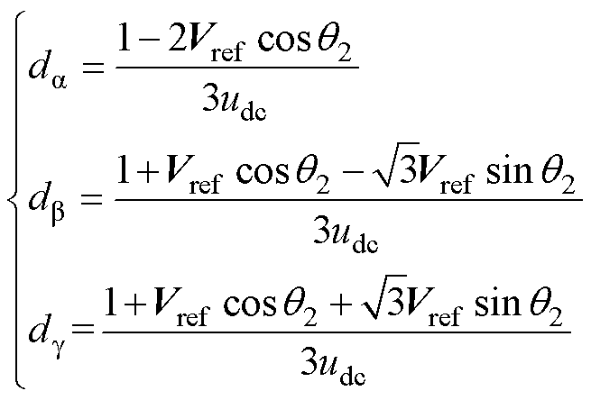 (7)
(7)
式中,da、db、dg 分别为有效电压矢量Va、Vb、Vg的占空比;q2为Vref与Va 的夹角,当输入扇区kin=1、3、5时,q2范围为p/3~2p/3,当kin=2、4、6时,q2范围为0~p/3。
电压传输比(Voltage Transfer Ratio, VTR)m定义为
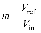 (8)
(8)
式中,Vref为参考输出电压幅值。为了在线性调制区域进行调制,式(7)中da、db 和dg 应保证均不小于0且三者之和不大于1,即本调制方法的最大线性输出电压为如图5b所示的三角形内切圆。通过VSI的特性可知,6个有效电压矢量的大小为2udc/3,则最大电压传输比为
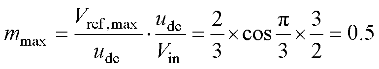 (9)
(9)
逆变级有效矢量的矢量排布顺序遵循文献[23]的排布原则,以避免逆变级有效矢量切换时带来的死区共模尖峰。以整流第1扇区和逆变第1扇区为例的新型调制策略的矢量排布如图6所示。
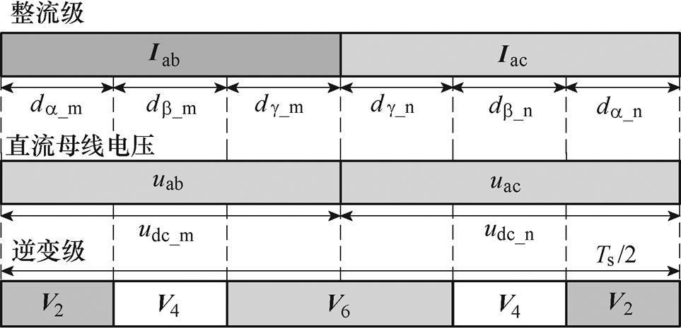
图6 本文新型调制策略的矢量排布
Fig.6 Vectors arrangement of the proposed stratery
图6中,Ts为一个采样周期,其余参数可表示为
 (10)
(10)
根据新型调制策略的调制原理,可获得每个输入扇区下的调制矢量及对应的共模电压幅值、峰值及正负特性,见表2。图7给出了一个输入周期的输出共模电压波形。由表2和图7可知,本文新型调制策略将共模电压峰值抑制到了各输入扇区最大线电压峰值1.737Vin的1/3,即0.579Vin,且共模电压的方向在一个整流级扇区内正负不发生变化,将大幅度降低高频共模幅值。
表2 各输入扇区下的调制矢量及共模电压
Tab.2 The vectors and corresponding CMV in each input sector
输入扇区 ImInVa、Vb、Vgucm共模电压正负共模电压峰值 1ImIabV2、V4、V6uac/3+0.579Vin InIacuab/3 2ImIacV1、V3、V5ucb/3- InIbcuca/3
(续)

输入扇区Im InVa、Vb、Vgucm共模电压正负共模电压峰值 3ImIbcV2、V4、V6uba/3+0.579Vin InIbaubc/3 4ImIbaV1、V3、V5uac/3- InIcauab/3 5ImIcaV2、V4、V6ucb/3+ InIcbuca/3 6ImIcbV1、V3、V5uba/3- InIabubc/3
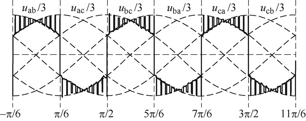
图7 一个输入周期的共模电压波形
Fig.7 The CMV waveforms in a input cycle
为进一步说明本文提出的调制策略在抑制高频共模电压性能上的优越性,选取电压调制比0~0.5下的IMC传统空间矢量调制(Space Vector Modulation, SVM)方法及文献[13]中方法一和文献[15]中方法二两种同样将共模电压峰值抑制了42.3%的调制策略,从时域和频域两个角度对共模电压特性进行对比分析。表3给出了这几种调制方法在一个输入扇区下的共模电压波形及在一个开关周期内的开关序列。
时域角度主要从一个输入扇区的共模电压正负特性以及一个开关周期的共模电压变化次数及变化幅值进行分析。nfc(n=0, 1, 2,…,fc为IMC的开关频率)频率处的共模电压幅值受共模电压在一个开关周期的正负变化次数及变化幅值的影响。从表3可以看出,传统SVM方法和其他两种共模电压峰值抑制策略的共模电压在一个输入扇区内含有正负值,且在一个开关周期内的变化次数多、幅值变化较大。本文提出的调制策略在一个输入扇区的共模波形与在一个开关周期的共模波形形状基本相同,只是幅值大小不同。在一个开关周期内,其共模电压变化次数最少,变化幅值也最小,因此共模电压高频幅值也相对减小。
表3 几种调制方法的开关序列和共模电压波形
Tab.3 Switching sequences and CMV waveforms for modulation methods
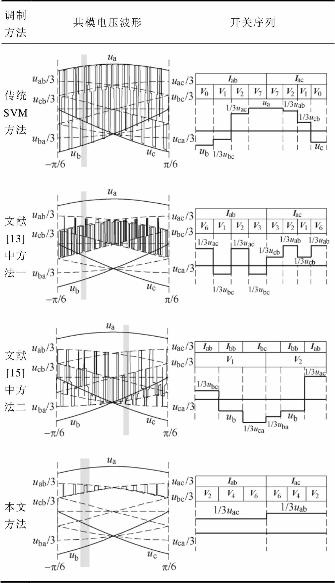
调制方法共模电压波形 开关序列 传统SVM方法 文献[13]中方法一 文献[15]中方法二 本文方法
图8给出了这四种调制方法基于傅里叶级数得到的共模电压频谱。从图中可以看出,文献[13,15]中的两种共模抑制策略较传统SVM方法,在某些电压传输比下或者某些高频段的共模电压幅值有所减小,但在其他情况下仍具有较高的幅值。如文献[13]中方法一在fc~3fc频段的共模幅值降低到了传统方法的20%~50%,但在4fc~6fc频段并未有明显的降低;文献[15]中方法二在电压传输比m=0.1和0.2下的共模电压幅值约为传统方法的20%~30%,但在m=0.3、0.4和0.5时,其fc~3fc频段的共模幅值并未有明显的降低。本文提出的新型调制策略的共模电压幅值虽在低频段处较高,但在电压传输比0.1~0.5下各高频段的幅值均不超过传统SVM方法的5%,相较于其他三种方法有明显大幅度的减小,且几乎不受电压传输比的影响。
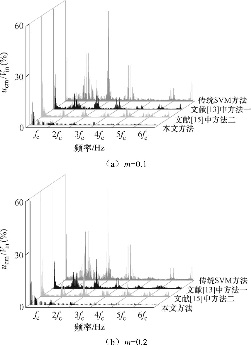
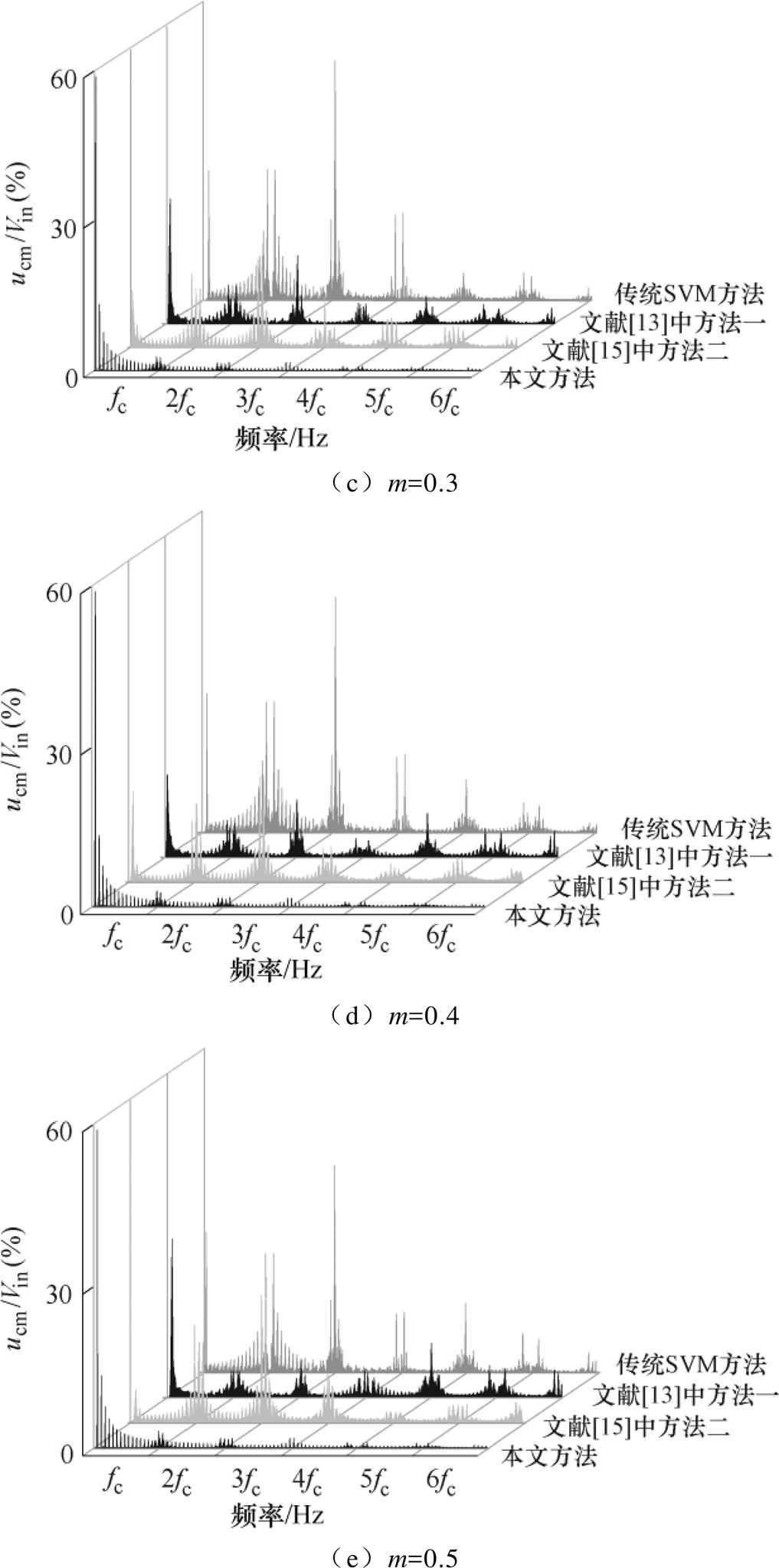
图8 不同电压传输比m下的共模电压频谱
Fig.8 The CMV spectrum under different transfer ratio m
为验证本文提出的一种大幅度减小IMC高频共模电压的调制策略的有效性,本文利用Matlab/ Simulink进行了仿真,仿真参数为:输入电压100 V/ 50 Hz,输入滤波电阻200 W、电感1.7 mH、电容10 mF,输出电压60 Hz,负载电感10 mH、电阻10 W,开关频率5 kHz。
图9为表3中四种调制方法在电压传输比m= 0.3下的仿真波形,自上而下分别是a相输入电流ia及A相输出电流iA,直流母线电压udc,输出线电压uAB,共模电压ucm及其FFT频谱。由图9可得,三种共模电压峰值抑制方法的输入输出电流均保持了良好的正弦性,且共模电压峰值均为57.7 V,相较于传统SVM方法的共模电压峰值100 V减小了42.3%。从共模电压的FFT频谱可以清楚地看到,本文方法相较于传统方法及其他两种相同共模电压峰值抑制方法,在各高频处的共模电压幅值均有大幅度的减小,仿真结果与理论分析结果一致。
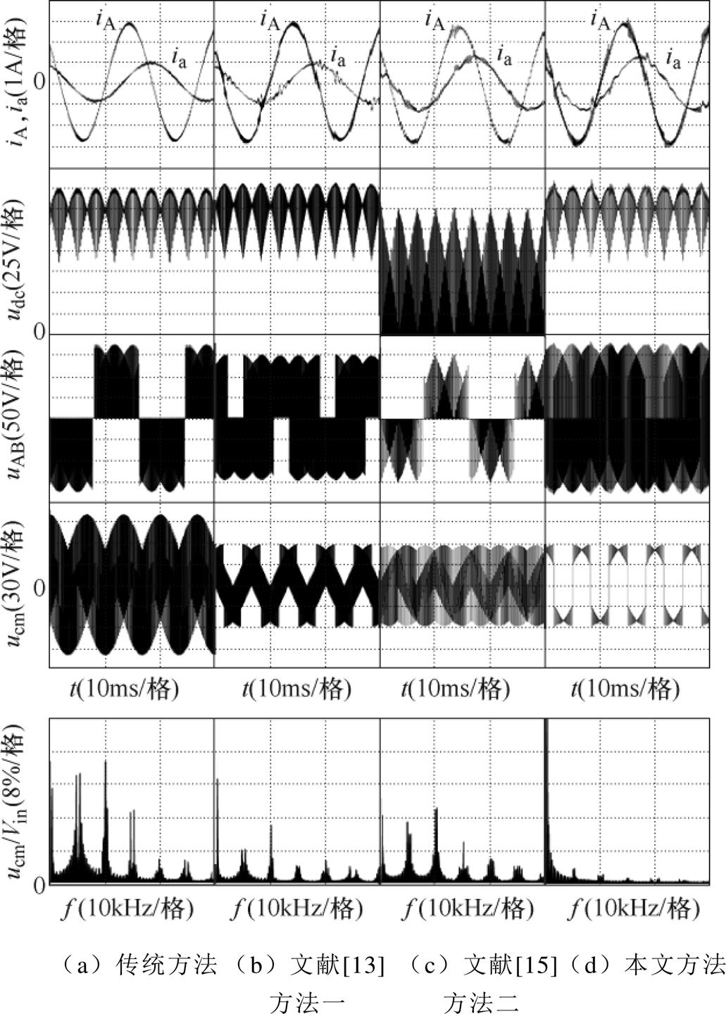
图9 m=0.3时的仿真波形及共模电压FFT分析
Fig.9 Simulink waveforms and common voltage FFT analysis under m=0.3
为证明上述理论分析结果及仿真结果的正确性,本文建立了如图10所示的IMC实验平台,该装置主要由采样电路、调理电路和主电路组成。调理电路包括DSP(TMS320F28335)电路和FPGA(CYCLONEIVEP4CE6)电路。主电路由输入滤波电路、整流级电路、钳位电路及逆变级电路组成,其中整流级由12个IGBT(FGL40N120AND)组成,逆变级由6个IGBT(FGL40N120AND)组成。其他实验参数与仿真参数相同。
图11为仿真中四种调制方法在电压传输比m= 0.3下的实验波形。从图11可以看出,传统SVM方法的共模电压峰值约为110 V,略高于输入相电压峰值100 V,这是由于非理想开关器件在开通和关断时产生的开关尖峰造成的。本文提出的策略与其他两个共模抑制策略的共模电压峰值约在63.5 V,相较于传统方法均将共模电压抑制了42.3%。相比于传统SVM方法,本文调制方法在一个载波周期内的开关次数增多,输入输出电流的输出波形质量有所降低,但正弦性良好。从四种方法共模电压实验波形的FFT频谱中可以看到,本文方法的共模电压幅值在所有高频段均有非常明显的降低。实验结果与上述理论分析结果及仿真结果相一致。
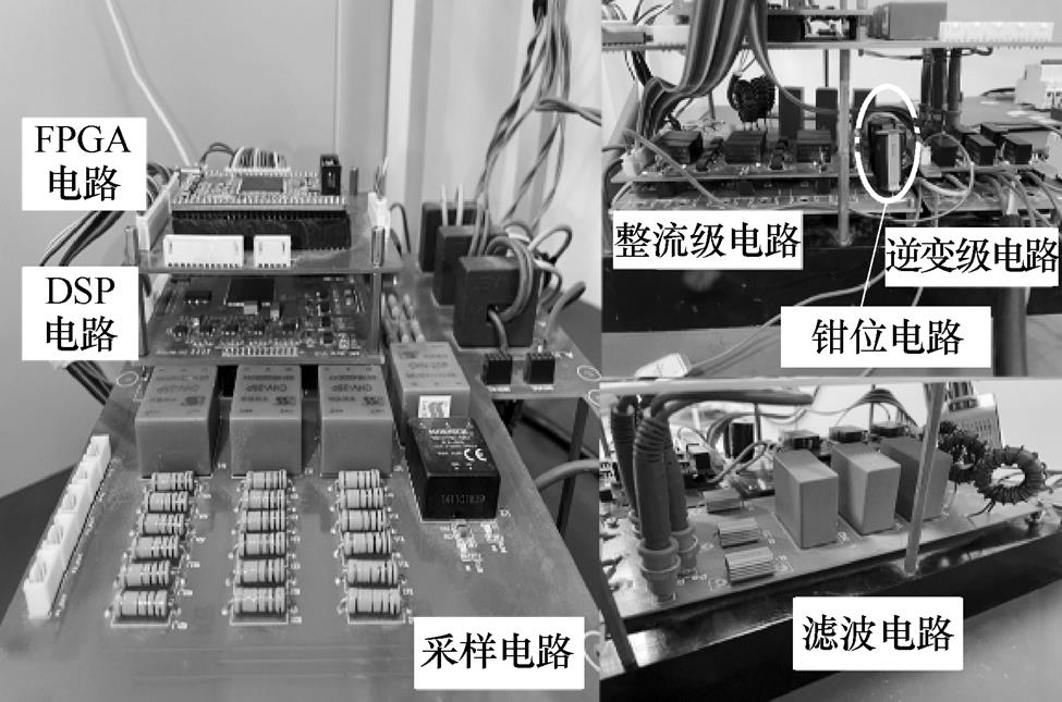
图10 IMC实验平台
Fig.10 Experiment platform of IMC

图11 m=0.3时的实验波形及共模电压FFT分析
Fig.11 Experimental waveforms and common voltage FFT analysis at m=0.3
本文提出一种大幅度减小间接矩阵变换器高频共模电压的调制策略。首先从时域角度进行分析,根据IMC有效矢量作用下的共模电压正负特性,选择使CMV在一个整流级扇区下正负方向不发生改变的有效矢量进行调制,通过减小共模电压的正负跳变次数和变化幅值有效抑制了高频共模电压。然后从频域角度,在相同电压传输比下与其他调制方法的共模电压频谱进行比较,分析该调制方法降低高频共模电压性能的优越性。最后仿真和实验结果均验证了该调制策略的有效性。
参考文献
[1] 孙盼, 孙军, 吴旭升, 等. 间接矩阵变换器优化SVPWM及其简化的同步控制[J]. 电工技术学报, 2019, 34(10): 2187-2193.
Sun Pan, Sun Jun, Wu Xusheng, et al. Optimized space vector pulse width modulation and simplified synchronization control of indirect matrix conver- ter[J]. Transactions of China Electrotechnical Society, 2019, 34(10): 2187-2193.
[2] Dan Hanbing, Zeng Peng, Xiong Wenjing, et al. Model predictive control-based direct torque control for matrix converter-fed induction motor with reduced torque ripple[J]. CES Transactions on Electrical Machines and Systems, 2021, 5(2): 90-99.
[3] 梅杨, 易高. 间接矩阵变换器-异步电机调速系统模型预测控制权重系数自整定方法[J]. 电工技术学报, 2020, 35(18): 3938-3948.
Mei Yang, Yi Gao. A weighting factor self-tuning method in model prediction control for indirect matrix converter with induction motor system[J]. Transa- ctions of China Electrotechnical Society, 2020, 35(18): 3938-3948.
[4] Wang Chao, Zheng Zedong, Wang Kui, et al. Analysis and control of modular multilevel matrix converters under branch fault conditions[J]. IEEE Transactions on Power Electronics, 2022, 37(2): 1682-1699.
[5] 邱继浪, 何英杰, 焦乾明, 等. 非隔离型三电平逆变器漏电流抑制与中点电位平衡控制[J]. 电力系统自动化, 2021, 45(17): 161-170.
Qiu Jilang, He Yingjie, Jiao Qianming, et al. Leakage current suppression and balance control of neutral point potential for three-level transformerless inverter[J]. Automation of Electric Power Systems, 2021, 45(17): 161-170.
[6] 王付胜, 李祯, 付航, 等. 一种抑制系统漏电流非隔离型三电平逆变器中点平衡载波调制算法[J]. 电工技术学报, 2017, 32(增刊2): 128-138.
Wang Fusheng, Li Zhen, Fu Hang, et al. A new pulse-width modulation algorithm for the com- prehensive neutral-point balancing and leakage current reducing in the three-level transformerless inverter[J]. Transactions of China Electrotechnical Society, 2017, 32(S2): 128-138.
[7] Xu Yang, Wang Zheng, Liu Pengcheng, et al. The modular current-fed high-frequency isolated matrix converters for wind energy conversion[J]. IEEE Transactions on Power Electronics, 2022, 37(4): 4779-4791.
[8] Yerkal S A, Aware M V, Umre B S, et al. Common mode voltage elimination in a three-to-six phase indirect matrix converter using SVM technique[C]// 2020 IEEE International Conference on Power Electronics, Drives and Energy Systems (PEDES), Jaipur, 2020: 1-6.
[9] Takahashi S, Ogasawara S, Takemoto M, et al. Common-mode voltage attenuation of an active common-mode filter in a motor drive system fed by a PWM inverter[J]. IEEE Transactions on Industry Applications, 2019, 55(3): 2721-2730.
[10] Jayaraman K, Kumar M. Design of passive common-mode attenuation methods for inverter-fed induction motor drive with reduced common-mode voltage PWM technique[J]. IEEE Transactions on Power Electronics, 2020, 35(3): 2861-2870.
[11] Kume T, Yamada K, Higuchi T, et al. Integrated filters and their combined effects in matrix con- verter[J]. IEEE Transactions on Industry Applications, 2007, 43(2): 571-581.
[12] 贾贵玺, 周晓畅, 李华. 高压变频器输出差模滤波器设计和共模电压抑制[J]. 电工技术学报, 2011, 26(增刊1): 161-165.
Jia Guixi, Zhou Xiaochang, Li Hua. Differential- mode filter design and common-mode voltage suppression at the high voltage VFD output ter- minals[J]. Transactions of China Electrotechnical Society, 2011, 26(S1): 161-165.
[13] Nguyen T D, Lee H H. Modulation strategies to reduce common-mode voltage for indirect matrix converters[J]. IEEE Transactions on Industrial Elec- tronics, 2012, 59(1): 129-140.
[14] Nguyen T D, Lee H H. A new SVM method for an indirect matrix converter with common-mode voltage reduction[J]. IEEE Transactions on Industrial Infor- matics, 2014, 10(1): 61-72.
[15] Padhee V, Sahoo A K, Mohan N. Modulation techniques for enhanced reduction in common-mode voltage and output voltage distortion in indirect matrix converters[J]. IEEE Transactions on Power Electronics, 2017, 32(11): 8655-8670.
[16] Tsoupos A, Khadkikar V. A novel SVM technique with enhanced output voltage quality for indirect matrix converters[J]. IEEE Transactions on Industrial Electronics, 2019, 66(2): 832-841.
[17] Su Mei, Lin Jianheng, Sun Yao, et al. A new modulation strategy to reduce common-mode current of indirect matrix converter[J]. IEEE Transactions on Industrial Electronics, 2019, 66(9): 7447-7452.
[18] Li Shanhu, Jin Zhaoyang, Liu Xu, et al. Open-current vector based SVM strategy of sparse matrix converter for common-mode voltage reduction[J]. IEEE Transa- ctions on Industrial Electronics, 2021, 68(9): 7757- 7767.
[19] Tran Q H, Nguyen T D, Phuong L M. Simplified space-vector modulation strategy for indirect matrix converter with common-mode voltage and harmonic distortion reduction[J]. IEEE Access, 2020, 8: 218489- 218498.
[20] Li Shanhu, Wang Wensheng, Han Xu, et al. A DPWM modulation strategy to reduce common-mode voltage for indirect matrix converters based on active-current vector amplitude characteristics[J]. IEEE Transa- ctions on Industrial Electronics, 2022, 69(8): 8102- 8112.
[21] 郭艳华. MMC逆变器传导干扰研究[D]. 北京: 中国舰船研究院, 2016.
[22] Cacciato M, Consoli A, Scarcella G, et al. Reduction of common-mode currents in PWM inverter motor drives[J]. IEEE Transactions on Industry Applications, 1999, 35(2): 469-476.
[23] Janabi A, Wang Bingsen. Hybrid SVPWM scheme to minimize the common-mode voltage frequency and amplitude in voltage source inverter drives[J]. IEEE Transactions on Power Electronics, 2019, 34(2): 1595-1610.
[24] Massrur H R, Niknam T, Mardaneh M, et al. Harmonic elimination in multilevel inverters under unbalanced voltages and switching deviation using a new stochastic strategy[J]. IEEE Transactions on Industrial Informatics, 2016, 12(2): 716-725.
[25] 史维硕, 张昌浩, 韩俊飞, 等. 大功率并联电流源变流器五电平特定谐波消除法[J]. 电力系统自动化, 2021, 45(13): 167-175.
Shi Weishuo, Zhang Changhao, Han Junfei, et al. Five-level selective harmonic elimination method for high-power parallel current source converter[J]. Automation of Electric Power Systems, 2021, 45(13): 167-175.
[26] 李珊瑚, 黄林峰, 王文圣, 等. 零电压矢量作用时间对间接矩阵变换器输出电压共模分量与谐波分量的影响分析[J]. 中国电机工程学报, 2022, 42(21): 7943-7955.
Li Shanhu, Huang Linfeng, Wang Wensheng, et al. Effect of two zero voltage vectors action time on the common-mode and harmonic components of output voltage of indirect matrix converter[J]. Proceedings of the CSEE, 2022, 42(21): 7943-7955.
Abstract An indirect matrix converter (IMC) is a new generation of AC-AC converter with broad application prospects in ships, aerospace, and wind power. IMC is composed of a rectifier and an inverter stage. Affected by the pulse width modulation (PWM), a high-frequency and high-amplitude common mode voltage (CMV) will be generated at the output during IMC operation. The CMV will damage the insulation layer of the motor winding, increase the mechanical wear of the bearing and shorten the service life of the motor. Therefore, the CMV must be suppressed. Most of the CMV suppression strategies focus on reducing the peak value. The high-frequency CMV amplitude is inhibited by adding active or passive filters to the CMV path, which not only increases the mention and cost of the system but also reduces the compactness of the IMC. Based on the amplitude and positive/negative characteristics of CMV for IMC under the action of each active vector, this paper proposes a new modulation strategy to reduce the high-frequency CMV of IMC significantly. This method significantly reduces the high-frequency CMV amplitude by decreasing the positive and negative transition times and amplitude change range of the CMV in a carrier cycle.
Firstly, the rectifier and inverter stages are both divided into six sectors. The positive/negative characteristics of the CMV under the action of each active vector in each input sector are analyzed. Secondly, use active vectors that keep the direction of the CMV unchanged within an input sector for modulation. The rectifier stage selects two adjacent active current vectors in each input sector to synthesize the reference input current vector. The inverter stage selects active voltage vectors V2, V4, V6 in input sectors 1, 3, 5 and selects V1, V3, V5 in input sectors 2, 4, 6 to synthesize the reference output voltage vector. Thirdly, according to the three-phase output current direction of each inverter stage sector and the freewheeling characteristics of the freewheeling switching diodes, the switching sequence of the inverter stage active voltage vectors is arranged rationally to eliminate the CMV spikes caused by the dead zone effect. Fourthly, the traditional space vector modulation (SVM) method and two classical CMV suppression modulation strategies of IMC are selected to compare with the proposed method from the time and frequency domains. The time domain compares the CMV waveforms within one input sector and the switching sequences within one switching cycle. The CMV amplitude at nfc ( fc is the switching frequency of the IMC) is affected by the number of amplitude changes and the magnitude of the change in a switching cycle. The high-frequency amplitude of CMV for the other three strategies is larger than the proposed method because the direction of the three methods is constantly changing in an input sector. The frequency domain compares the CMV spectrum obtained by the triple Fourier transform of these four methods under the voltage transfer ratio (VTR) of 0.1~0.5. The CMV amplitude decreases under a specific VTR or frequency band, but it is still high in other cases. The CMV amplitude of the new method does not exceed 5% of the traditional SVM method in each high-frequency band and is almost unaffected by the VTR. Finally, simulations and experiments are carried out on the above four methods. The simulation and experiments confirm that the proposed strategy can suppress the CMV by 42.3% compared with the traditional method and greatly reduce the CMV amplitude of each high-frequency band.
keywords:Indirect matrix converter (IMC), high-frequency common-mode voltage, positive and negative characteristics, modulation strategy
DOI: 10.19595/j.cnki.1000-6753.tces.221038
中图分类号:TM46
国家自然科学基金项目(51907049)、河北省自然科学基金项目(E2020202095)、河北省自然科学基金创新群体项目(E2020202142)和中央引导地方科技发展资金项目(226Z1805G)资助。
收稿日期 2022-06-02
改稿日期 2022-08-01
鲁紫荆 女,1998年生,硕士研究生,研究方向为间接矩阵变换器共模电压抑制。E-mail: 202021401045@stu.hebut.edu.cn
李珊瑚 女,1985年生,副教授,硕士生导师,研究方向为电机驱动控制与可靠性分析、伺服运动控制、变换器建模与控制。E-mail: shanhuli@hebut.edu.cn(通信作者)
(编辑 陈 诚)