考虑状态受限的微电网二次电压与频率固定时间控制
吴忠强 程洪强
(燕山大学工业计算机控制工程河北省重点实验室 秦皇岛 066004)
摘要 该文研究孤岛交流微电网二次电压和频率的固定时间精确控制问题,基于多智能体一致性方法,提出考虑状态受限的自适应模糊固定时间二次电压控制器和基于控制障碍函数的二次频率控制器。在多智能体一致性控制中,将每一个分布式电源视为一个非线性智能体,智能体之间通过稀疏网络进行通信。在电压控制器设计中,采用反馈线性化后未知变量的自适应模糊估计提高控制器的自适应能力,并引入新的滑模面使电压控制器在固定时间内收敛。考虑到系统状态受限问题,分别采用障碍Lyapunov函数和控制障碍函数设计电压与频率控制器,使系统状态在预设的约束范围内。频率控制器的设计还考虑了有功功率的精确分配问题,给出了严格的固定时间收敛及稳定性证明。在Matlab/Sim Power System环境下,对微电网负载变化及大干扰下的仿真验证了所提控制器的有效性。
关键词:微电网 固定时间 障碍Lyapunov函数 自适应模糊估计 分布式二次控制 控制障碍函数
0 引言
随着新能源的开发利用和电网技术的发展,以集中和单一供电方式为主要特征的电力系统存在稳定性及不适合偏远地区等问题[1]。微电网是未来电网发展的主流方向。微电网既是传统电网向智能电网的过渡,也是未来智能电网建设中不可或缺的重要组成部分[2]。微电网是单独的可控制的实体,可以由多个分布式电源(Distributed Generation, DG)按通信拓扑网络构成,其中分布式电源及负载通过开关和公共耦合点与大电网并网连接,可有效减少间歇电源对大电网的冲击。微电网的发展与先进的电力电子技术、控制技术、通信技术紧密相关,是目前重点研究和发展的方向[3-4]。
微电网控制可分为一次控制、二次控制和三次控制。一次控制包括电流内环控制和下垂控制。二次控制分为集中式、分散式和分布式控制。三次控制一般为微电网的能量管理控制。文献[5]研究了基于下垂控制的微电网小信号动态模型,采用遗传算法对微电网小信号动态模型的运行特性进行优化,提高了系统的动态性能,但所提出的控制器并未将电压和频率恢复至参考值。二次控制可弥补一次控制所产生的电压和频率偏差。文献[6-8]对孤岛微电网采用分散式二次控制恢复电压和频率。所采用的方法只需要本地信息,降低了通信复杂度,但分散控制存在单个电源无法获得其他电源信息的问题,难以协调全局信息,影响整体控制目标。文献[9-11]对孤岛微电网采用分布式二次控制来恢复电压和频率。该方法基于多智能体系统,通过稀疏网络通信实现分布式电源间的相互协调,消除了单点故障给系统带来的影响,其中,文献[11]提出一种基于牵制的交流微电网集群分层分布式二次协同控制策略,同时实现了包括频率、电压调节和有功、无功功率均分等多个控制目标。
在微电网二次电压和频率控制中,系统收敛速度取决于所设计控制器的收敛时间。文献[9,12-13]采用全分布式和自适应控制方法恢复微电网的电压和频率。所提出的控制方案都属于无限时间控制问题,系统的收敛速度有待进一步提高,因此,研究电压和频率的有限时间恢复更具实际意义。文献[11,14-16]基于反馈线性化方法,设计了分布式鲁棒有限时间二次电压和频率控制器,所设计的控制器具有良好的鲁棒性和抗干扰性能,但未考虑输出受限及即插即用等情况。文献[17]采用一种新的网状拓扑结构,在有限时间内对电压和频率进行二次控制,所提出的控制器支持即插即用功能。文献[15,18-19]采用有限时间滑模控制对微电网的电压和频率进行二次控制,以保持系统的稳定性并加快收敛速度,但滑模控制含有微分运算,计算量大,系统输出的抖振现象比较明显。文献[20]提出一种基于扩展卡尔曼滤波器和快速终端滑模的二次电压控制方法。运用扩展卡尔曼滤波器精确估计模型状态信息,使用快速终端滑模控制加快了系统的收敛速度。但是,未考虑二次频率恢复及有功功率分配问题。
有限时间收敛可在有限的时间内使误差为零,区别于渐近收敛(时间无穷大时,误差才为零)。然而有限时间收敛与系统的初始状态有关,在实际应用中,由于系统的初始状态往往无法提前获得,则无法得到具体的有限时间。而固定时间收敛不但具有可在有限的时间内使误差为零,还与初始状态无关,仅与控制器参数有关,只要知道控制器的参数,则有限的时间即可计算出来,更具实际应用价值。且在实际系统中普遍存在状态受限问题。如果系统不满足约束条件,不仅会降低系统的安全性能,甚至会导致整个系统不稳定。在微电网中,电压、频率等实际物理状态往往不可避免地受到一定程度的约束。同时,由于网络带宽和传输速率的限制,在网络中传输信息也需要加以限制。在文献[21]中,研究了电压频率受限的交流微电网二次控制问题。采用模型预测控制方法求解状态受限问题。在文献[22]中,采用分布式鲁棒控制方法,约束输出频率,保持微网的弹性运行。
针对上述问题,本文设计了一种考虑状态受限的自适应模糊固定时间电压控制器和频率控制器。首先,对微电网系统采用反馈线性化处理,对反馈线性化后的未知变量及内部扰动由自适应模糊系统进行估计;然后,设计新的滑模面和滑模趋近律,使电压在固定时间内迅速收敛到参考值;最后,考虑输出约束问题,利用障碍Lyapunov函数(Barrier Lyapunov Function, BLF)对电压误差进行约束,使输出电压约束在预设范围内。对于频率控制,设计了基于控制障碍函数的频率控制器,将输出频率约束在预设范围内,同时保证有功功率精确分配。
1 预备知识和问题描述
1.1 图论
微电网可以视为一个多智能体系统,其分布式共识协调控制可以用有向图和无向图等来表示。设图 ,其中顶点集
 ,边集
,边集 ,
, 表示笛卡尔积。矩阵
 为图G的邻接矩阵,其中,
 表示一个N节点的G中边的权重系数。当且仅当
 时,意味着顶点j可以接收到来自顶点i的信息,否则
 。在图中,顶点的度是指与该顶点相连的边的个数。对于有向图,有入度和出度之分,入度就是所有从
 出发的边的个数,出度就是所有指向的边的个数。此外,定义入度矩阵D与图拉普拉斯矩阵L分别为:
 ,
, 。根据对角入度矩阵D的定义:
 ,对于有向图来说,L矩阵的每一行元素之和等于0,但对于无向图,L矩阵的每一行元素和每一列元素之和都等于零[23]。
1.2 引理
引理1[24]:对于 ,式(1)成立。
式中, 和
和 分别为
分别为 的估计和估计误差,满足
 。
。
引理2[25]:令 ,
, ,
, ,则有
,则有
 (3)
(3)
引理3[26]:考虑连续非线性系统
假设存在一个连续可微的的正定函数 ,且常数
,且常数 ,
, ,
, ,
, ,
, ,有
,有
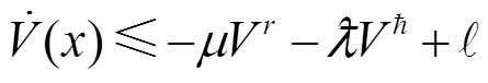 (5)
(5)
那么,称系统式(4)是实际固定时间稳定的,其收敛时间为
1.3 基于逆变器的分布式电源大信号动态模型
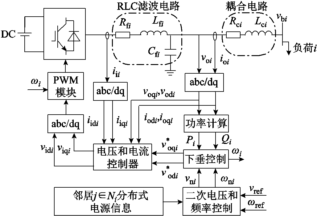
交流微电网的第i个逆变器的控制框图如图1所示,包含分布式电源、逆变器、PWM模块、功率计算模块、电压和电流控制器等[27]。
图1中, 和
和 分别为第i个分布式电源的额定角频率和电压,
 和
和 分别为第i个RLC滤波电路的输出电压和电流,
 和
和 分别为第i个RLC滤波电路输出电压的d、q分量,
 和
和 分别为第i个RLC滤波电路输出电流的d、q分量;
 和
和 分别为第i个下垂控制产生的电压d、q分量,
 为第i个下垂控制产生的角频率,
 为第i个逆变器输出电流,
 和
和 分别为第i个逆变器输入电压的d、q分量,
 和
和 分别为第i个逆变器输出电流的d、q分量,
 为第i个分布式电源母线电压,
 、
、 、
、 分别为第i个RLC滤波器的电阻、电感、电容,
 、
、 分别为第i个耦合线路的电阻和电感,
 和
和 分别为第i个低通滤波电路输出的有功功率和无功功率。
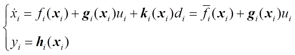
对于电压源逆变器,文献[28]研究了RLC滤波电路和耦合电路,以及电压电流控制电路的动态模型。图1所示的微电网分布式电源大信号状态空间表达式[29]可以写为
式中,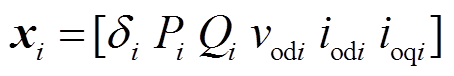 为系统的状态变量;
 ,
, 为扰动;
为扰动; 为输入;
为输入; 为输出;
为输出;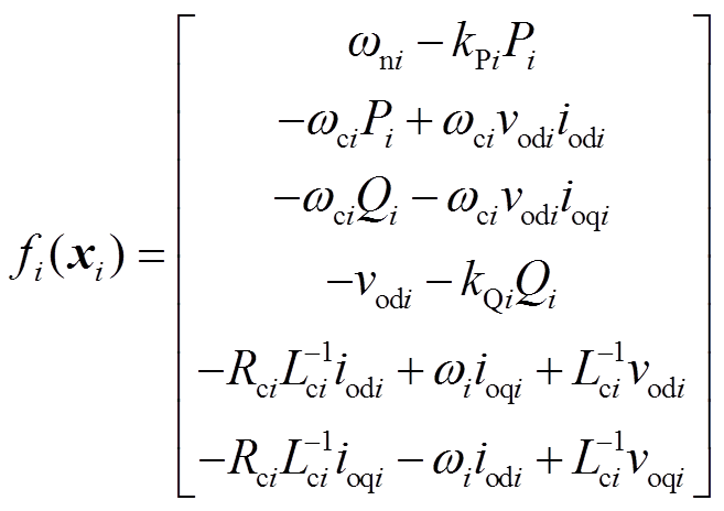 ;
; ;
; ;
; 。
。
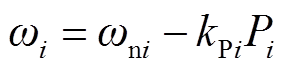
下垂控制方程为
 (9)
(9)
 (10)
(10)
式中, 和
和 分别为频率和电压下垂控制系数;和可由式(11)和式(12)得到。
 (12)
(12)
式中, 为低通滤波剪切频率。
微电网经过下垂控制后可以实现功率分配,但下垂控制是有差调节,无法使输出电压和频率精确到参考值,因此需要对电压和频率进行二次调节。
在微电网中,由于线路阻抗不匹配,难以实现准确的无功功率分配。准确的电压控制会导致无功功率分配的误差。反过来,精确的无功功率分配会导致电压控制不良。因此,需要在精确的电压控制和无功功率的分配之间平衡。一般情况下,精确的电压控制和无功功率的共享是无法同时实现的,除非增加硬件(或采用虚拟阻抗法)来减少有功功率和无功功率之间的耦合。由于这不是本文的重点,因此本文只考虑精确的电压调节。
2 分布式二次电压控制器的设计
由于基于下垂控制的电压调节会产生偏差,因此需要设计二次电压控制来调节下垂控制引起的偏差。微电网二次电压控制是一个跟踪问题。本节首先设计分布式二次电压固定时间控制器,通过误差跟踪使输出电压达到一致。对于每个非线性系统,采用李导数法对系统进行反馈线性化,并采用自适应模糊系统估计系统的未知部分;然后,设计了一种新的滑模面和滑模趋近律,使电压在固定时间内收敛;最后,考虑状态约束问题,利用BLF设计控制器,使系统状态约束在预设范围内。
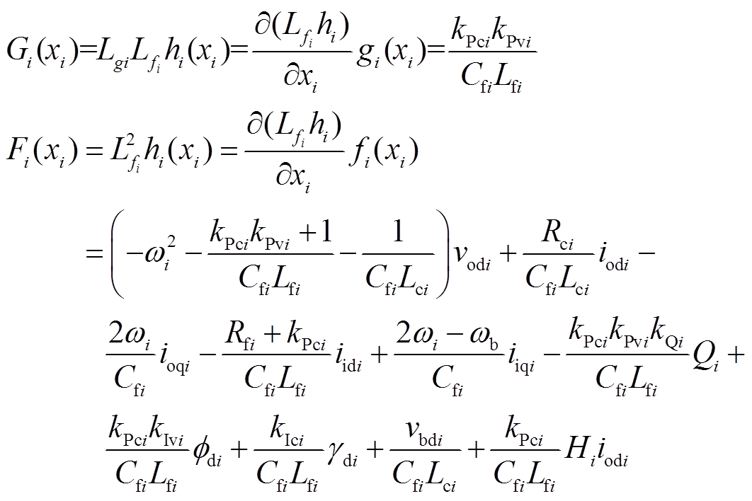
设输出为 ,对非线性系统式(7)采用李导数反馈线性化得
 (14)
(14)
其中
式中, 为微电网额定频率;
 、
、 、
、 、
、 分别为电压和电流控制回路的比例、积分增益[20]。
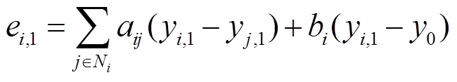
利用一致性协议,设计DG输出电压误差函数为
 (16)
(16)
式中, ;
; ;
; ;bi为控制增益,
 ;
; 为第i个控制器的通信邻域集。
对式(16)求导并将式(14)代入得
式中, 。
。
2.1 控制器的设计和滑模面的改进
首先,选择非奇异终端滑模面,有
式中, ;
; 为滑模面系数,
 ;sign(·)为符号函数。
BLF是解决系统状态约束问题的控制方法[30-31]。在实际运行过程中,由于执行器的影响,系统的状态变量受到一定的限制。为了限制系统状态严格收敛于期望状态,可以构造BLF使系统稳定,使系统状态始终在给定的受限范围内。
跟踪误差的受限范围为
式中, 。
。
将误差归一化为
提出的滑模面可以改写为
 (21)
(21)
式中, 。
。
对式(21)求导,并将式(14)和式(17)代入整理可得
选择BLF为
 (23)
(23)
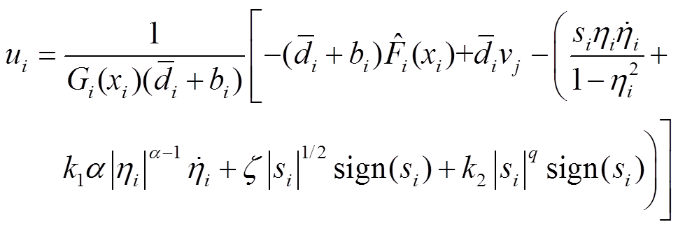
对于反馈线性化系统式(14),基于非奇异终端滑模面式(18),在考虑状态约束的情况下,采用BLF方法设计控制器,有
式中, ;
; ;
; ;
; 为
为 的估计;
的估计; 为设计的滑模趋近律。
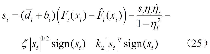
将式(24)代入式(22)得
2.2 针对系统不确定性的自适应模糊估计
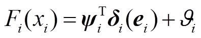
由于系统式(14)中的涉及一些未知变量,采用自适应模糊系统进行估计。将表示为如式(26)所示的模糊函数形式。
式中, 、
、 为模糊系统的权向量,
 ,
, ;
; 为最小模糊逼近误差;
 为模糊基函数向量,
 。
。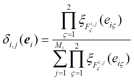 ,其中,
,其中, 为隶属度函数,Mi为模糊规则的总数。
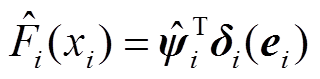
由式(26)可得
式中, 为的估计;
为的估计; 。
。
选取自适应律为
式中, 和
和 大于0。
大于0。
2.3 稳定性证明
考虑Lyapunov函数如下
式中, 为权向量的估计误差,
 。
。
对式(29)求导并将式(25)代入,得
整理式(30)并将式(28)代入,得
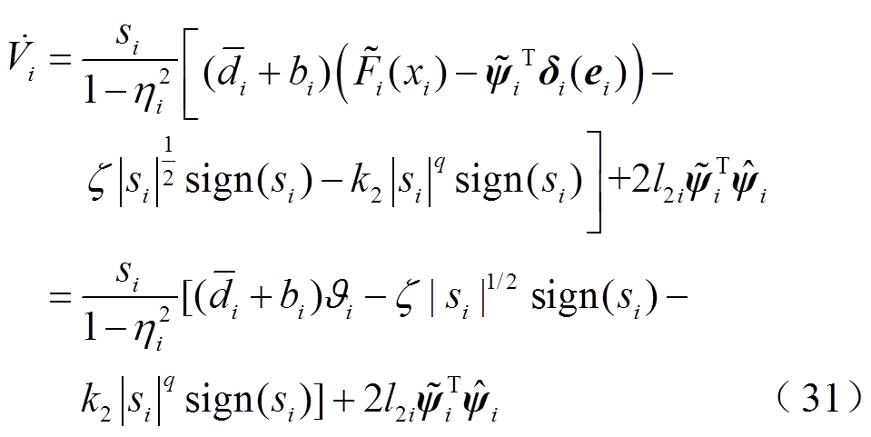
由引理1和式(31)可知
式中, ;
; 。
。
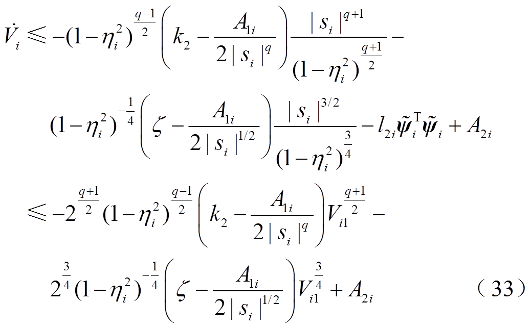
对于式(32),有
由式(33)并结合引理2,有
 (34)
(34)
其中
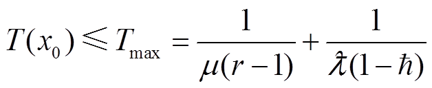
由引理3可知,所设计的控制器是实际固定时间稳定的,其稳定时间可估计为
 (35)
(35)
证毕。
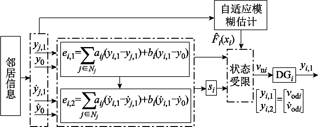
图2为固定时间二次电压控制框图,由图2可知,当分布式电源运行时,控制输入 时刻更新。
时刻更新。
3 分布式二次频率控制器的设计
在本节中,设计二次频率控制使 ,以补偿下垂控制产生的频率偏差,且让跟随者跟随领航者,使频率在固定时间内达到一致,并使输出频率在受限的范围内,即
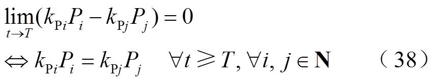
有功功率根据分布式电源额定容量比,按如下比例进行分配
 (37)
(37)
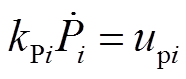
为了恢复分布式二次频率,对式(8)求导得
 (39)
(39)
设
为了实现精确的有功功率分配,设计 为
为
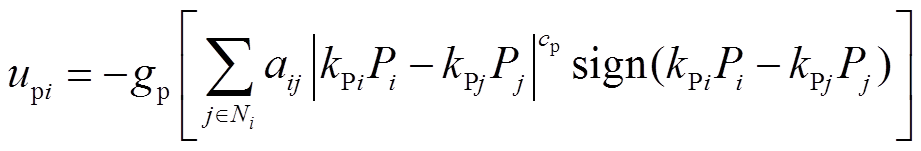 (41)
(41)
式中, ,
, 。
。
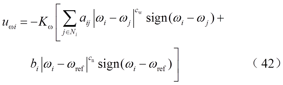
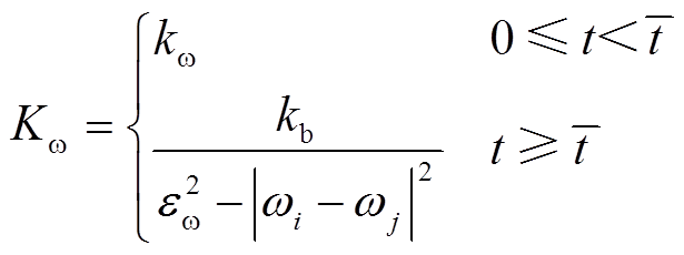
考虑状态约束条件,设计 为
为
式中, ;
; 。
。
状态约束条件为
式中, ;
; ;
; 为辅助时间变量,可以根据所需的控制精度来选择;
 为与
为与 的误差约束边界,
 ,满足
,满足 。
。
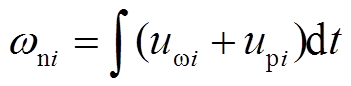
根据式(39)和式(40),频率二次控制设定点输入为
4 仿真与结果分析
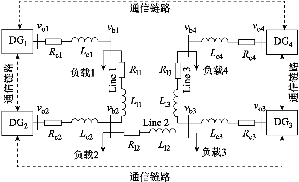
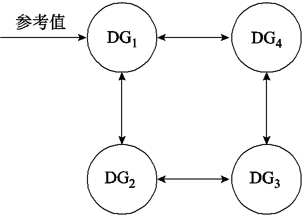
本节中,在Matlab/Sim Power Systems软件环境下,搭建直流电压源为800 V,逆变器电压为380 V,频率为50 Hz的孤岛交流微电网,通过负载变化及部分通信中断、时变拓扑及大干扰下的仿真来验证所设计的二次电压频率控制器的有效性。微电网分布式电源通信框图如图4所示,由DG、负载和RL线路组成[32]。采用双向有向图的稀疏网络通信,降低系统对故障的敏感性,通信拓扑图如图5所示。在图5中,将电压和频率的参考输入给DG1作为领航者。分布式电源模型、负载和RL线路的一些参数见表1和表2,所提出方案的控制参数见表3。
表1 分布式电源的模型参数
Tab.1 Model parameters of DG
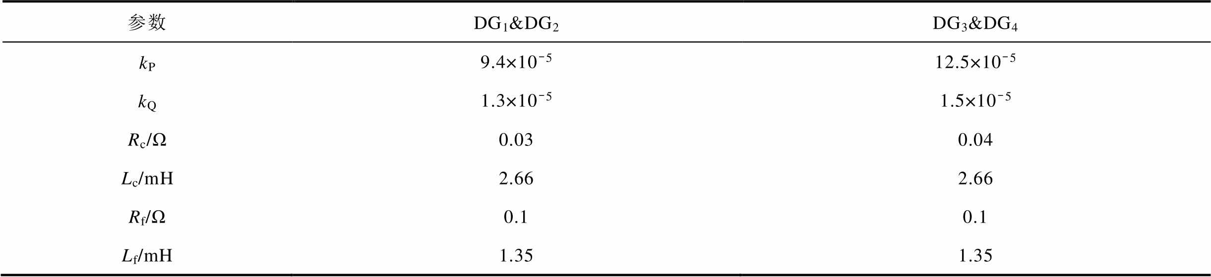
参数DG1&DG2DG3&DG4 kP9.4×10-512.5×10⁻⁵ kQ1.3×10-51.5×10⁻⁵ Rc/Ω0.030.04 Lc/mH2.662.66 Rf/Ω0.10.1 Lf/mH1.351.35
(续)
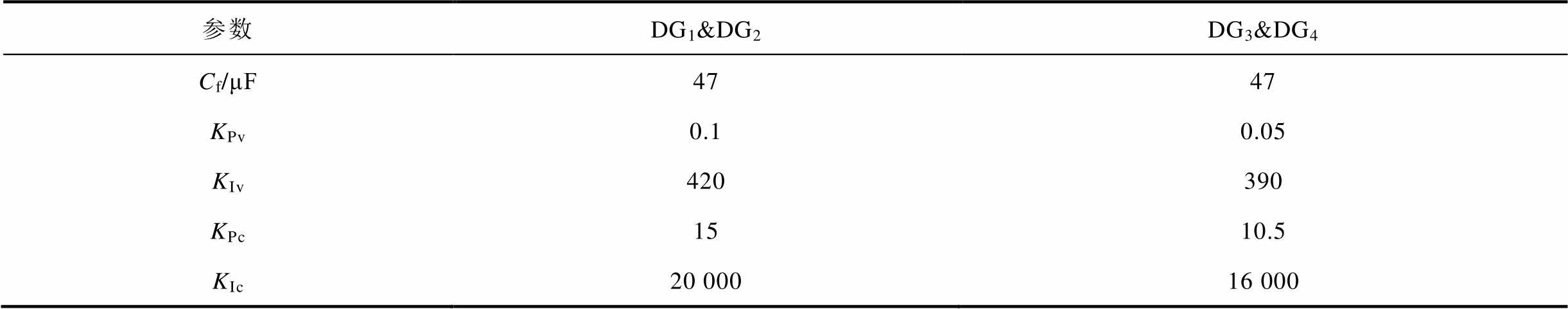
参数DG1&DG2DG3&DG4 Cf/μF4747 KPv0.10.05 KIv420390 KPc1510.5 KIc20 00016 000
表2 负载和RL线路的一些参数
Tab.2 Some parameters of load and RL line
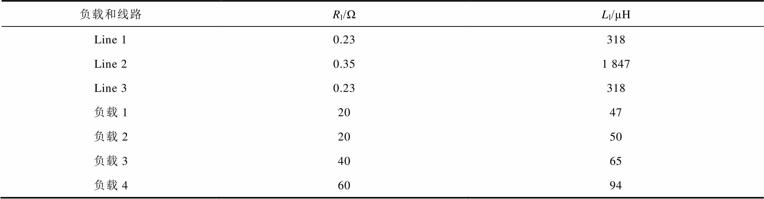
负载和线路Rl/ΩLl/μH Line 10.23318 Line 20.351 847 Line 30.23318 负载12047 负载22050 负载34065 负载46094
表3 所提出的控制方案的参数
Tab.3 Parameters of the proposed control scheme
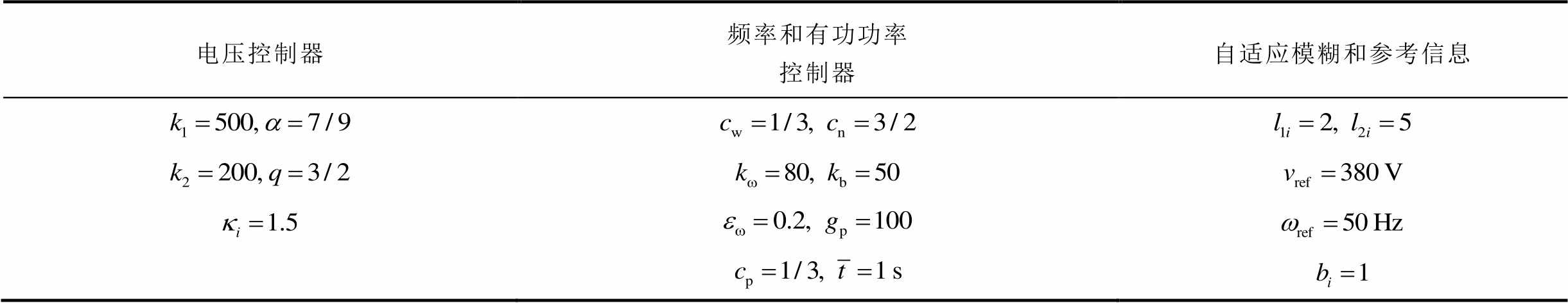
电压控制器频率和有功功率控制器自适应模糊和参考信息
自适应模糊系统采用的隶属度函数为
 。
。
4.1 二次控制在负载变化以及阻抗线路故障下的性能验证
为了验证所提出的二次控制在负载变化及阻抗线路故障下的性能。假设: s,当
s,当 时,只有微电网一次控制;当
 时,二次控制被激活,所提出的控制器开始运行;当
 时,负载2增大50%;当
 时,负载3减小25%;当
 时,负载1增大50%;当
 时,负载1恢复至原始值;当
 时,Line 3断开;当
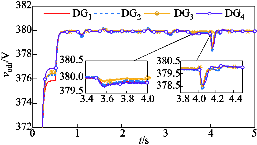
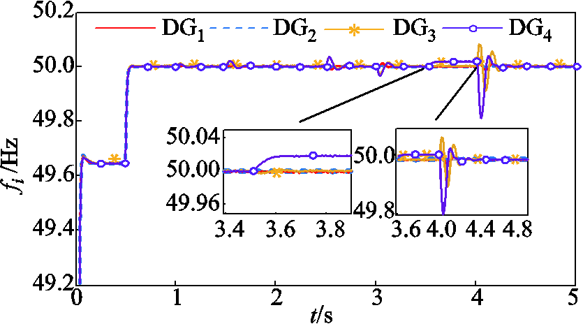
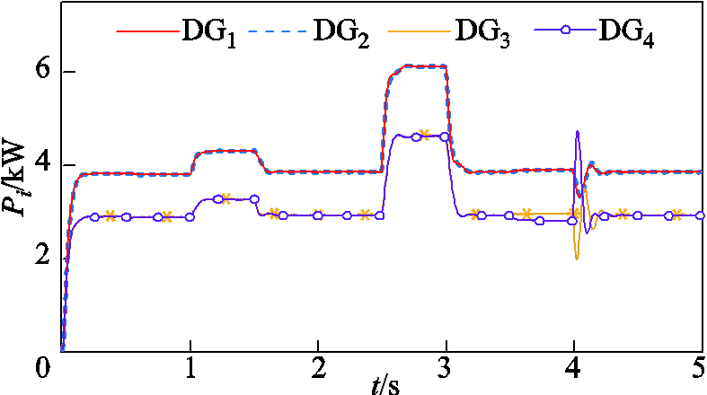
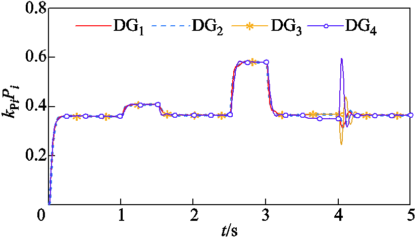
 时,Line 3重新连接。分布式二次电压、频率控制和有功功率以及功率比的仿真结果如图6~图9所示。
由图6和图7可知,仅有下垂控制,电压和频率虽然可渐近稳定,但并没有达到参考值。当二次控制被激活时,所提出的控制器使电压和频率在固定时间内快速且精确地跟随参考输入。对应负载变化及Line 3断开和重新接入的情况,在Line 3断开时,DG4只服务于负载4,而DG1、DG2和DG3共同负担微电网中的其他负载,由图8和图9可知,此时电压、频率及有功的变化并不大,说明此时与Line 3断开前的各DG负担微电网负载的情况相差不大。当Line 3接入时,DG4和DG1、DG2、DG3共同负担微电网中的总负载,同时由于Line 3接入使整个电路的电感和电阻增加,易发生振荡,会使电压和频率的瞬态变化增加,因此波动比Line 3断开时(整个电路的电感和电阻减小)略大。由图8和图9可知,有功功率按比例实现了精确分配。
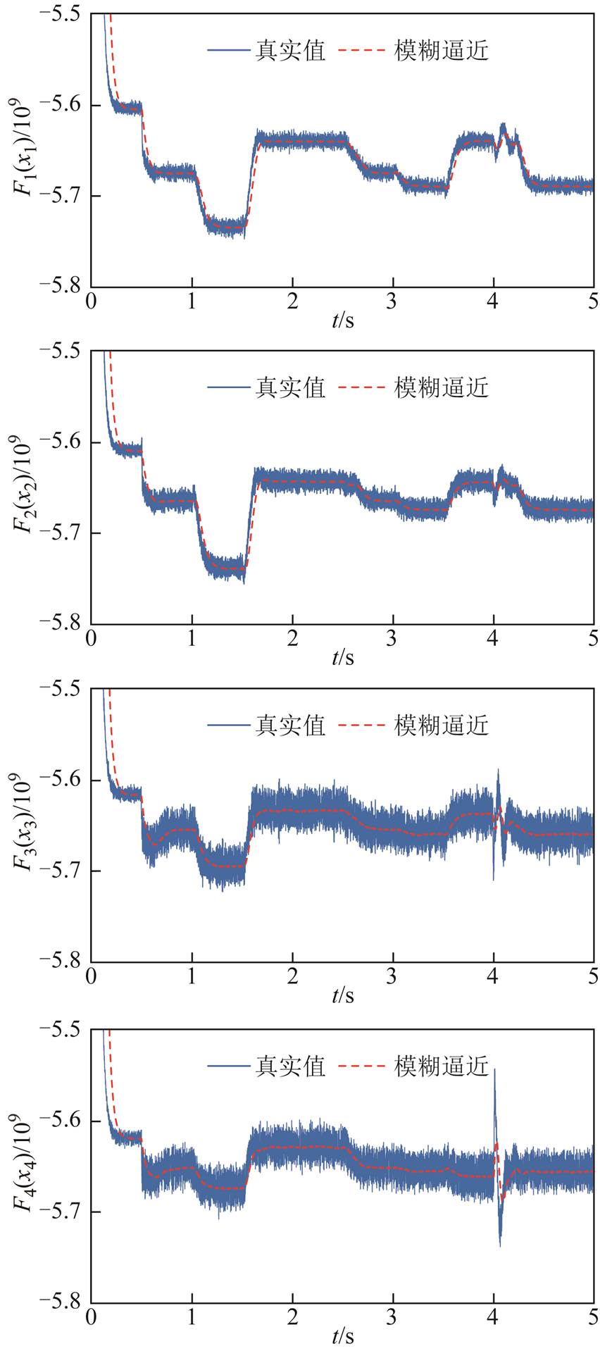
自适应模糊系统逼近系统不确定项结果如图10所示。
由图10可看出,自适应模糊系统对 有良好的逼近效果。
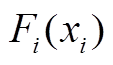
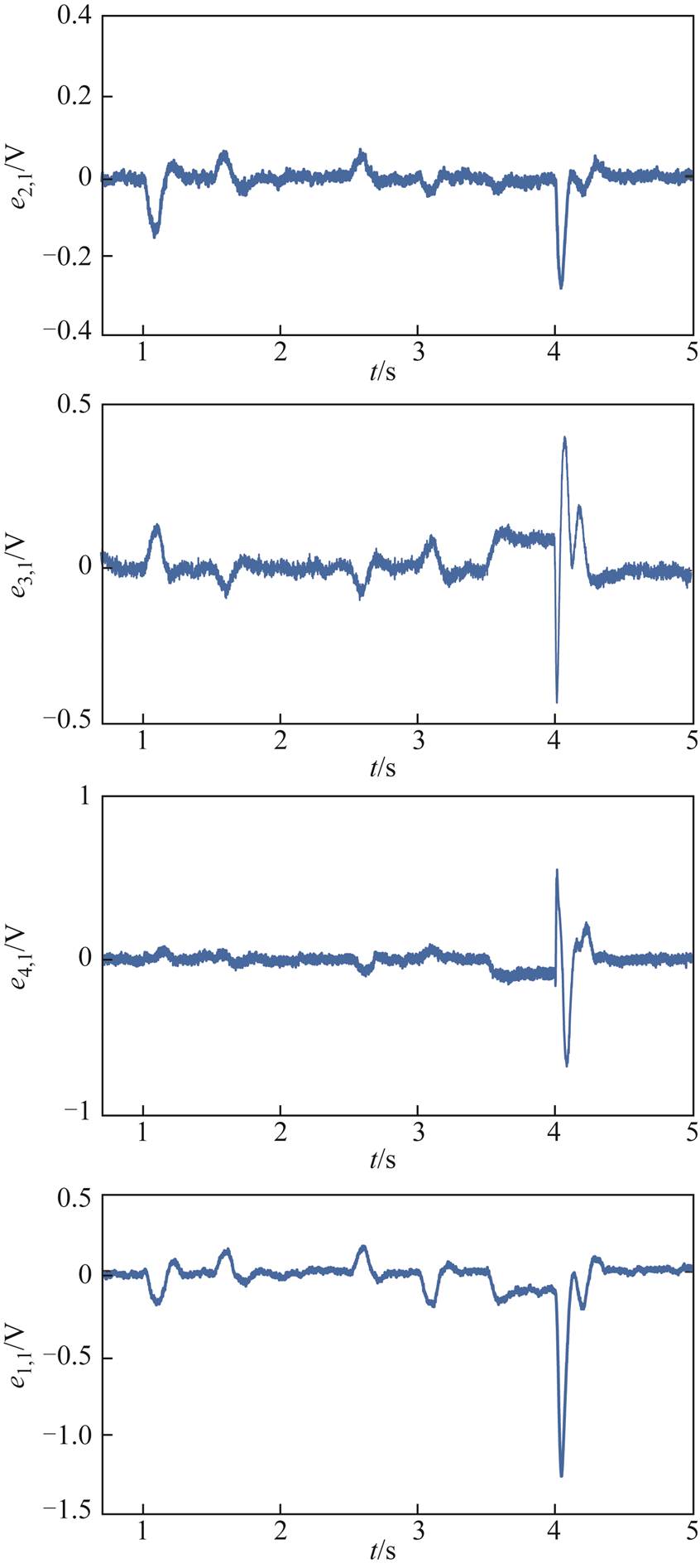
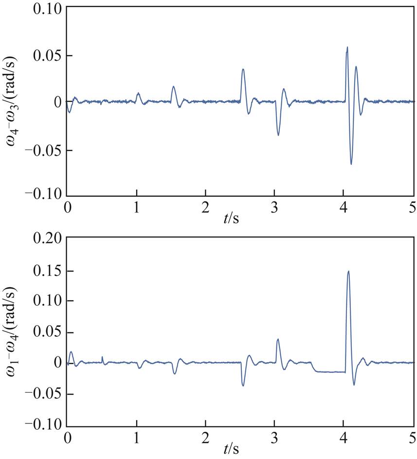
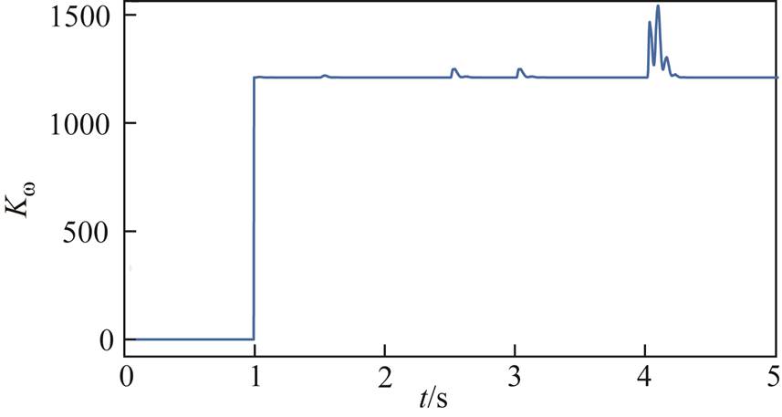
分布式二次电压和频率输出误差及状态约束条件 变化如图11~图13所示。
图11和图12是在图5的通信拓扑结构下,第i个DG的电压输出误差和频率输出误差。由此可看出,所设计的控制器在BLF约束下,输出误差始终在预设范围 和
和
 内。由图13可知,辅助时间变量s后,在负载变化和阻抗线路故障情况下,
 短暂变化后稳定运行,体现出频率二次控制器设计方法的优越性。
4.2 二次控制在大扰动下的状态约束性能验证
由于大的负载突变及扰动等因素,会给电压和频率带来大的瞬态变化,可能对系统性能造成严重影响,因此需验证所设计的二次电压和频率控制器在大扰动下,对输出的限制能力。假设时,负载2增大50%;当 时,负载3减小25%;
 时将负载1增加5倍,并将其与传统的无输出受限的二次电压和频率控制相比较,通信拓扑仍采用图5方式。仿真结果如图14和图15所示。
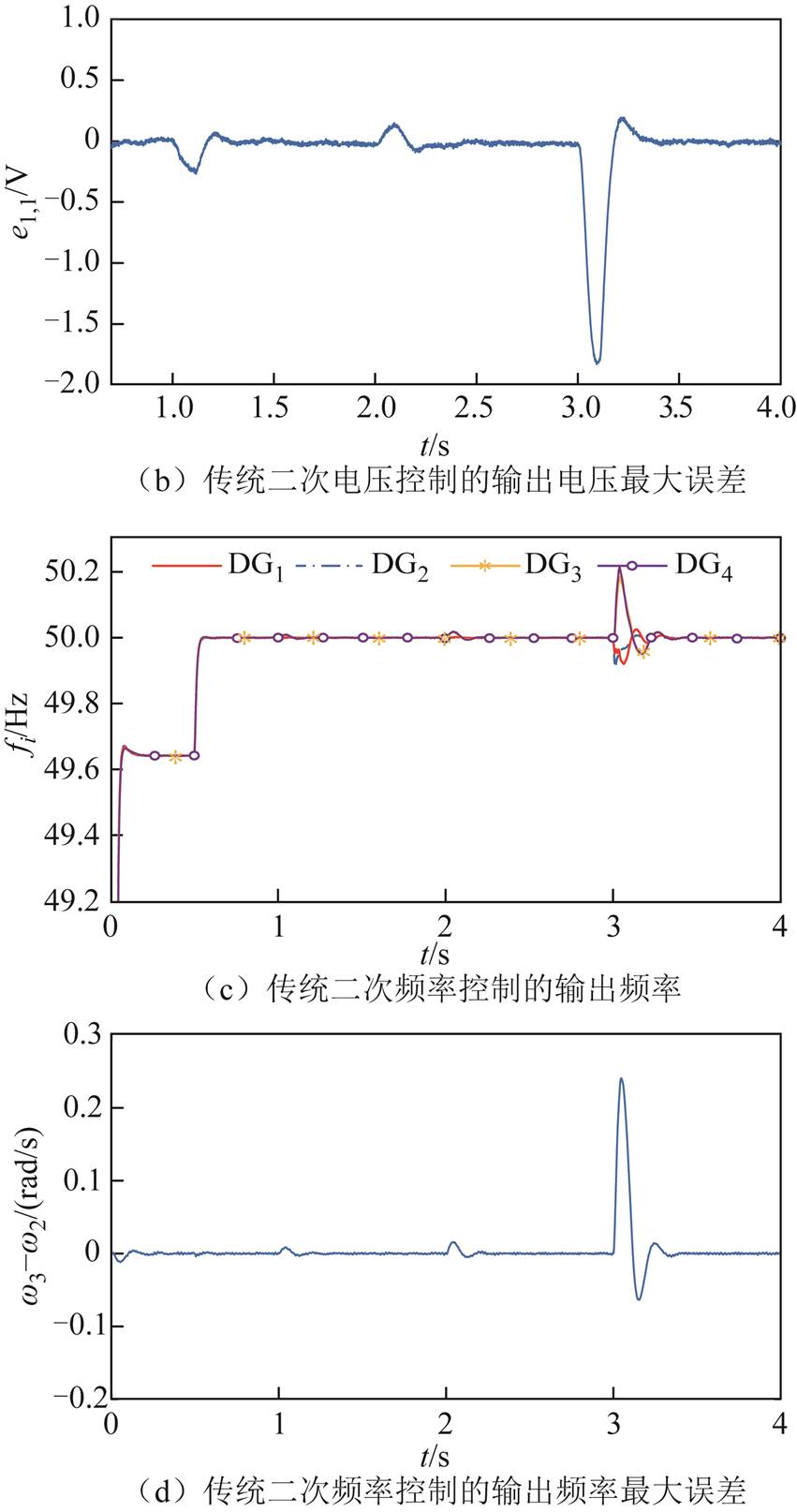
图14a~图14d分别是传统无输出受限的二次电压和频率控制及最大误差。其中,由图14b和图14d可看出,当负载变化不大时,电压误差和频率误差均在受限范围内,分别是二次电压控制误差的最大相差误差 和二次频率控制的最大相差误差
 。当负载变化较大时,电压最大误差为1.85 V,超过预设误差,频率最大误差为0.25 Hz,超过预设误差
 。
。
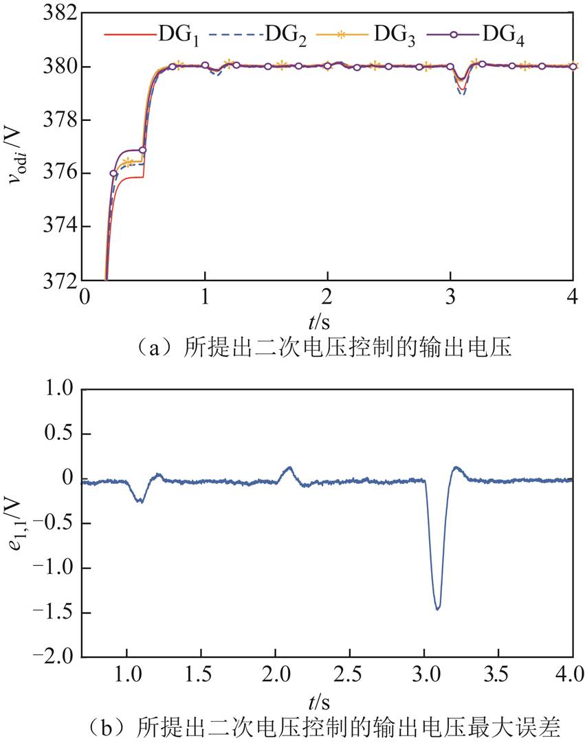
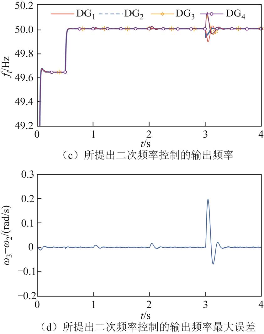
图15a~图15d是考虑输出受限的二次电压和频率控制及最大误差。由图15b和图15d可看出,无论是当负载变化不大还是当负载变化较大时,电压和频率的最大误差均在预设受限范围 和
和 以内。仿真表明所设计的二次控制器对系统输出具有很强的约束能力。
5 结论
针对微电网二次控制存在偏差及调节时间长等问题,本文提出一种考虑状态受限的电压控制器和频率控制器。结合BLF法设计了一种新的自适应模糊实际固定时间电压控制器,使系统电压全局固定时间收敛,并对系统的参数变化具有自适应能力,同时使跟踪误差在预设范围内以约束输出电压。基于控制障碍函数设计频率控制器使跟踪误差在预设范围内以约束输出频率,同时实现有功功率的精确分配。仿真结果表明,在负载变化和阻抗线路故障以及大扰动情况下,所提控制策略可以使系统实际固定时间收敛,与传统二次控制方法相比,具有状态约束能力和较强的鲁棒性。未来将研究考虑通信延时以及网络攻击下的微电网固定时间二次控制问题。
参考文献
[1] 王晴, 刘增, 韩鹏程, 等. 基于变流器输出阻抗的直流微电网下垂并联系统振荡机理与稳定边界分析[J].电工技术学报, 2023, 38(8): 2148-2161. Wang Qing, Liu Zeng, Han Pengcheng, et al. Analysis of oscillation mechanism and stability boundary of droop-controlled parallel converters based on output impedances of individual converters in DC microgrids[J]. Transaction of China Electrotechnical Society, 2023, 38(8): 2148-2161.
[2] Golsorkhi M S, Shafiee Q, Lu D, et al. Distributed control of low-voltage resistive AC microgrids[J]. IEEE Transactions on Energy Conversion, 2019, 34: 573-584.
[3] 黄文焘, 邰能灵, 刘剑青, 等. 微电网多层级协同反时限保护方案[J]. 电工技术学报, 2021, 36(3): 623-633. Huang Wentao, Tai Nengling, Liu Jianqing, et al. Multi-layer collaborative inverse-time protection schemes for microgrids[J]. Transactions of China Electrotechnical Society, 2021, 36(3): 623-633.
[4] Bidram A, Davoudi A. Hierarchical structure of microgrids control system[J]. IEEE Transactions on Smart Grid, 2012, 3(4): 1963-1976.
[5] Yu Kai, Ai Qian, Wang Shiyi, et al. Analysis and optimization of droop controller for microgrid system based on small-signal dynamic model[J]. IEEE Transactions on Smart Grid, 2016, 7(2): 695-705.
[6] Etemadi A H, Davison E J, Iravani R. A generalized decentralized robust control of islanded microgrids[J]. IEEE Transactions on Power Systems, 2014, 29(6): 3102-3113.
[7] Liu Baojin, Wu Teng, Liu Zeng, et al. A small-AC-signal injection-based decentralized secondary frequency control for droop-controlled islanded microgrids[J]. IEEE Transactions on Power Electronics, 2020, 35(11): 11634-11651.
[8] Li Qiang, Chen Feixiong, Chen Minyou, et al. Agent-based decentralized control method for islanded microgrids[J]. IEEE Transactions on Smart Grid, 2016, 7(2): 637-649.
[9] Wu Xiangyu, Shen Chen, Iravani R. A distributed, cooperative frequency and voltage control for microgrids[J]. IEEE Transactions on Smart Grid, 2018, 9(4): 2764-2776.
[10] Das A, Shukla A, Shyam A B, et al. A distributed-controlled harmonic virtual impedance loop for AC microgrids[J]. IEEE Transactions on Industrial Electronics, 2021, 68(5): 3949-3961.
[11] Wu Xiangyu, Xu Yin, He Jinghan, et al. Pinning-based hierarchical and distributed cooperative control for AC microgrid clusters[J]. IEEE Transactions on Power Electronics, 2020, 35(9): 9865-9885.
[12] Xin Huanhai, Zhang Leiqi, Wang Zhen, et al. Control of island AC microgrids using a fully distributed approach[J]. IEEE Transactions on Smart Grid, 2015, 6(2): 943-945.
[13] Amoateng D O, Al Hosani M, Elmoursi M S, et al. Adaptive voltage and frequency control of islanded multi-microgrids[J]. IEEE Transactions on Power Systems, 2018, 33(4): 4454-4465.
[14] Dehkordi N M, Sadati N, Hamzeh M. Distributed robust finite-time secondary voltage and frequency control of islanded microgrids[J]. IEEE Transactions on Power Systems, 2017, 32(5): 3648-3659.
[15] Pilloni A, Pisano A, Usai E. Robust finite-time frequency and voltage restoration of inverter-based microgrids via sliding-mode cooperative control[J]. IEEE Transactions on Industrial Electronics, 2018, 65(1): 907-917.
[16] Zuo Shan, Davoudi A, Song Yongduan, et al. Distributed finite-time voltage and frequency restoration in islanded AC microgrids[J]. IEEE Transactions on Industrial Electronics, 2016, 63(10): 5988-5997.
[17] Riverso S, Sarzo F, Ferrari-Trecate G. Plug-and-play voltage and frequency control of islanded microgrids with meshed topology[J]. IEEE Transactions on Smart Grid, 2015, 6(3): 1176-1184.
[18] Yan Huaicheng, Zhou Xuping, Zhang Hao, et al. A novel sliding mode estimation for microgrid control with communication time delays[J]. IEEE Transactions on Smart Grid, 2019, 10(2): 1509-1520.
[19] Ge Pudong, Dou Xiaobo, Quan Xiangjun, et al. Extended-state-observer-based distributed robust secondary voltage and frequency control for an autonomous microgrid[J]. IEEE Transactions on Sustainable Energy, 2020, 11(1): 195-205.
[20] Ge Pudong, Zhu Yue, Green T C, et al. Resilient secondary voltage control of islanded microgrids: an ESKBF-based distributed fast terminal sliding mode control approach[J]. IEEE Transactions on Power Systems, 2021, 36(2): 1059-1070.
[21] Dong Xiaogang, Gan Jinqiang, Wu Hao, et al. Self-triggered model predictive control of AC microgrids with physical and communication state constraints[J]. Energies, 2022, 15(3): 1170.
[22] Chu Zhongda, Zhang Ning, Teng Fei. Frequency-constrained resilient scheduling of microgrid: a distributionally robust approach[J]. IEEE Tran-sactions on Smart Grid, 2021, 12(6): 4914-4925.
[23] 米阳, 蔡杭谊, 宋元元, 等. 基于同步补偿的孤岛微电网无功均分研究[J]. 电工技术学报, 2019, 34(9): 1934-1943. Mi Yang, Cai Hangyi, Song Yuanyuan, et al. Study on reactive power sharing of island microgrid based on synchronous compensation[J]. Transactions of China Electrotechnical Society, 2019, 34(9): 1934-1943.
[24] 陈子聪, 王林, 刘建圻, 等. 带输入饱和的不确定非线性系统自适应模糊触发式补偿控制[J]. 控制与决策, 2021, 36(12): 3007-3014.Chen Zicong, Wang Lin, Liu Jianqi, et al. Adaptive fuzzy trigger compensation control for uncertain nonlinear system with input saturation[J]. Control and Decision, 2021, 36(12): 3007-3014.
[25] 陈刚, 李志勇, 韦梦立. 孤岛微电网的分布式固定时间二次协调控制[J]. 控制与决策, 2019, 34(1): 205-212. Chen Gang, Li Zhiyong, Wei Mengli. Distributed fixed-time secondary coordination control of islanded microgrids[J]. Control and Decision, 2019, 34(1): 205-212.
[26] Chen Ming, Wang Huanqing, Liu Xiaoping. Adaptive practical fixed-time tracking control with prescribed boundary constraints[J]. IEEE Transactions on Circuits and Systems I: Regular Papers, 2021, 68(4): 1716-1726.
[27] Zuo Shan, Ali Beg O, Lewis F L, et al. Resilient networked AC microgrids under unbounded cyber attacks[J]. IEEE Transactions on Smart Grid, 2020, 11(5): 3785-3794.
[28] 肖湘宁, 王鹏, 陈萌. 基于分布式多代理系统的孤岛微电网二次电压控制策略[J]. 电工技术学报, 2018, 33(8): 1894-1902. Xiao Xiangning, Wang Peng, Chen Meng. Secondary voltage control in an islanded microgrid based on distributed multi-agent system[J]. Transactions of China Electrotechnical Society, 2018, 33(8): 1894-1902.
[29] Abhinav S, Schizas I D, Ferrese F, et al. Optimization-based AC microgrid synchronization[J]. IEEE Transactions on Industrial Informatics, 2017, 13(5): 2339-2349.
[30] Xu Bin, Shi Zhongke, Sun Fuchun, et al. Barrier Lyapunov function based learning control of hypersonic flight vehicle with AOA constraint and actuator faults[J]. IEEE Transactions on Cybernetics, 2019, 49(3): 1047-1057.
[31] Fuentes-Aguilar R Q, Chairez I. Adaptive tracking control of state constraint systems based on differential neural networks: a barrier Lyapunov function approach[J]. IEEE Transactions on Neural Networks and Learning Systems, 2020, 31(12): 5390-5401.
[32] 孙伟, 方昭, 杨建平, 等. 考虑随机时变延时的孤岛微电网分布式二次控制[J]. 中国电机工程学报, 2022, 42(3): 864-875. Sun Wei, Fang Zhao, Yang Jianping, et al. Distributed secondary control of islanded microgrid with stochastic time-varying delay[J]. Proceedings of the CSEE, 2022, 42(3): 864-875.
Fixed-Time Secondary Voltage and Frequency Control for Microgrid Considering State-Constrained
Wu Zhongqiang Cheng Hongqiang
(Key Laboratory of Industrial Computer Control Engineering of Hebei Province Yanshan University Qinhuangdao 066004 China)
Abstract Microgrid is one of the most effective and flexible means to manage and control the distributed generation. In microgrid control, the convergence rate of closed-loop system is considered as one of the performance indexes of the control system design. Therefore, it is necessary to analyze the influence of the convergence rate in the control system on the system performance. Finite time convergence can make the error converge to zero in a finite time. However, finite time convergence is related to the initial state of the system. In practical application, because the initial state of the system cannot be obtained in advance, so the specific convergence time cannot be obtained. Meanwhile, the state constrained problem is common in real systems. If the constrained condition does not be met in a system, it will cause the security performance of the system to decline, even may make the whole system unstable. In the microgrid, the physical states such as voltage and frequency are usually constrained to a certain extent. For example, the change of bus voltage should not exceed 10% and the change of frequency should not exceed 2%, otherwise it will seriously affect the stable operation of the system. So, in this paper, based on the multi-agent consensus method, an adaptive fuzzy practical fixed time secondary voltage controller considering state constraints and the secondary frequency controller based on control barrier function are proposed.
First of all, the microgrid is regarded as a distributed multi-agent system, and each agents communicate with each other through a sparse network. To solve the deviation problem caused by droop control, based on the multi-agent consensus protocol, secondary control is used to adjust the output voltage, frequency and active power. Secondly feedback linearization is applied to the microgrid system, for the system uncertainty and internal disturbance, adaptive fuzzy estimation is designed to improve the adaptive ability of the controller. A new sliding surface is introduced to design the voltage controller, which makes it converge in practical fixed time, so as to accelerate the convergence speed of the system. The fixed time convergence does not depend on the initial state of the system, but only depends on the parameters of the designed controller, which is conducive to the calculation of convergence time. Finally, considering the problem of system state constraints, the barrier Lyapunov function is used to design the voltage controller, so that the system voltage is constrained within the preset range. The fixed time frequency controller is designed based on cooperative control method of consensus protocol and the control barrier function, and the accurate sharing of active power is realized.
The following conclusions can be drawn from the simulation analysis: In the case of load variation, impedance line fault and large disturbance, the proposed controller makes the voltage and frequency follow the reference input quickly and accurately in a fixed time, and the adaptive fuzzy system has a good approximation effect on the system uncertainty and internal disturbance. Compared with the traditional secondary control, the maximum errors of voltage and frequency are within the preset constraint range using the proposed controller, which have the ability of state constraint and strong robustness, at the same time the stability of the system is improved.
Keywords: Microgrid, fixed time, barrier Lyapunov function, adaptive fuzzy estimation, distributed secondary control, control barrier function
DOI:10.19595/j.cnki.1000-6753.tces.220723
中图分类号:TM734; TP229
河北省自然科学基金资助项目(F2020203014)。
收稿日期 2022-05-04
改稿日期 2023-04-10
作者简介
吴忠强 男,1966年生,教授,研究方向为微电网控制及优化调度。E-mail: mewzq@163.com(通信作者)
程洪强 男,1996年生,硕士,研究方向为微电网二次控制。E-mail: chqxsi123@163.com
(编辑 赫蕾)
 (1)
(1)
 (2)
(2)
 (4)
(4)
 (6)
(6)
 (7)
(7)
 (8)
(8)
 (11)
(11)
 (13)
(13)
 (15)
(15)
 (17)
(17)
 (18)
(18)
 (19)
(19)
 (20)
(20)
 (22)
(22)
 (24)
(24)
 (26)
(26)
 (27)
(27)
 (28)
(28)
 (29)
(29)
 (36)
(36)
 (40)
(40)
 (43)
(43)
 (44)
(44)
 时刻更新。
时刻更新。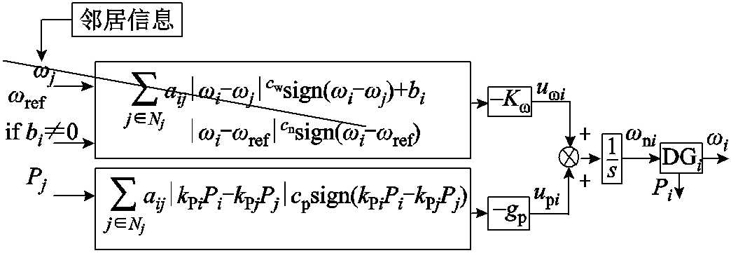
 变化
变化