 为正极接地故障、
 为负极接地故障、
 为双极短路故障、
 为整流侧交流系统故障。图1b为全-半混合型MMC拓扑结构,由全桥子模块(Full Bridge sub-module, FB)和半桥子模块(Half Bridge sub-module, HB)构成,全桥子模块比例为70%,具有故障自清除能力。本文对系统发生直流故障、交流故障下的桥臂功率进行分析,提出基于桥臂功率特征的保护方案。
摘要 全-半混合型柔性直流输电系统具有故障自清除能力,能在一定程度上解决因高压直流断路器技术滞后导致的柔性直流输电容量提升困难问题,是新能源发电大容量远距离输出的解决方案之一。但全-半混合型柔性直流输电对保护时间提出了更高要求,需要在更短时间内实现故障识别。该文基于能量观点分析了直流线路故障下桥臂功率特征,提出基于桥臂功率特征的全-半混合型柔性直流输电线路保护方法,能够在1 ms内识别直流线路故障,实现故障选极。最后,通过大量实时数字模拟(RTDS)实验验证了该方法的可靠性高、选择性好,且具有较强的耐过渡电阻能力和抗干扰能力。
关键词:全-半混合型 柔性直流输电 等效电路 桥臂功率特性 直流线路保护
“双碳”目标是构建以新能源为主体的新型电力系统的主要驱动力[1],基于模块化多电平换流器(Modular Multilevel Converter, MMC)的柔性直流输电凭借其控制灵活、线路损耗低、无换相失败等优点[2-5],在大规模新能源并网输电中得到了广泛的应用[6-8]。柔性直流输电相比于基于电网换相换流器(Line Commutated Converter, LCC)的传统高压直流输电具有低阻尼特性,当直流输电线路发生故障时,故障电流发展迅速,在几毫秒内就能达到额定电流的数十倍[9-10],造成电力电子功率器件不可逆损坏,甚至导致输电系统瘫痪,给电网安全运行带来严重危机。因此快速而有选择地辨识直流线路故障是亟待解决的关键技术之一[11]。由于新能源外送需要更大容量的柔性直流系统,但直流断路器技术限制了柔性直流输电容量的增长[12],采用具有自清除能力的全-半混合型柔性直流结构成为柔性直流大容量输电解决方案之一。昆柳龙高压直流工程受端采用全-半混合型MMC结构[13],电压达±800 kV,最大容量达5 000 MW,针对全-半混合型柔性直流输电系统的保护研究,对新能源大规模外送具有重要意义[14-15]。
目前关于柔性直流输电线路保护的研究主要集中在半桥结构,通过断路器清除故障电流的点对点直流和柔性直流电网方面,主要包括电流差动保护和行波暂态量保护等。文献[16-17]分别提出了基于单端电气量的电流微分保护方法和电压微分保护方法,能够有效提高保护的快速性,但没有考虑过渡电阻对该方法的影响。文献[18]提出基于电流变化量的快速电流差动保护,但未考虑线路分布式电容对保护的影响。文献[19]提出基于平波电抗器电压变化率的保护方案,该方法能够消除分布式电容的影响,但也没有考虑过渡电阻的影响。文献[20]提出基于高速电流差分的保护方法,利用直流电流天然测量特性减少测量时间,并进行了硬件实验测试,但该文献并没有给出具体的保护算法。电流差动保护算法能够实现快速的故障线路保护,但保护效果受电流互感器饱和、分布电容电流等影响,且电流差动保护只在直流控制稳态阶段有效。文献[21]提出在不同运行方式下行波的解析表达式,分析了直流线路行波在故障点及线路末端折反射规律,为直流线路行波保护奠定了理论基础;文献[22]通过极波广义变化率构造保护判据,该保护方法能够有效地提升保护灵敏度,具有较好的保护效果,但该方法计算量较大;文献[23]提出基于电压比自适应调整保护定值的极线行波保护原理,该方法能够提高行波保护耐受过渡电阻能力和抗干扰能力,但该保护方案需要的时间较长,不适用于全-半混合型柔性直流输电系统;文献[24]以极波变化率作为保护启动判据,以极波斜率区分雷电干扰和短路故障,以极波差值构造故障选极判据,提出一种适用于柔性直流输电线路的改进行波保护,但该方法对行波采样率要求高。“网孔”型柔性直流电网,如张北电网由于有冗余回路,线路保护有特殊性,某一线路故障时,相邻非故障线路的电气量也会有变化,需要甄别;同时故障清除前,原则上最多有一个换流站因为过电流而闭锁。为满足以上要求,一方面要求换流阀具备一定的故障电流耐受能力,尽可能不发生闭锁;另一方面,直流电网的保护系统应能快速检测与定位直流故障,目前直流系统保护装置检测和定位直流故障的最短时间为3 ms,该时间也将作为张北直流电网保护系统的基本设计参数[25]。基于此,文献[26]提出了方向行波积分值的纵联保护,该保护能可靠识别非故障线路,且不依赖边界元件,但需考虑光纤通道延时是否满足3 ms的要求。文献[27]提出不依赖于边界元件的架空型多端柔性直流电网就地测距式接地保护原理,其速动性比方向纵联保护具有明显的优势。
目前昆柳龙高压直流输电工程采用全-半混合型子模块拓扑结构,该工程线路保护采用行波保护原理。由于全-半混合型换流阀具有故障自清除能力,在故障后2~3 ms内进行故障自清除控制,完整故障信息只能获取到1 ms左右,提高了对保护方法快速性的要求,而现行保护存在对远端高阻识别不灵敏等问题。文献[28]提出基于行波相位特征的混合直流输电线路保护方案,该方案能能够有效地应对高阻故障,但未分析噪声对保护方法的影响;文献[29]提出基于检测混合型MMC结构的柔性直流电压变化量以启动直流故障穿越的控制策略方案,实现故障自清除;文献[30]提出基于极波、地波变化量的混合直流线路保护方案,但未考虑过渡电阻和噪声干扰对保护方法的影响。
综上所述,本文以全-半混合型柔性直流输电系统为研究对象,对直流线路故障下桥臂功率进行解析,从能量观点分析了桥臂功率的变化特征,提出基于桥臂功率特征的全-半混合型柔性直流输电系统保护方案,利用故障后1 ms桥臂功率信息,能够实现故障可靠、快速检测和故障隔离,具有良好的耐过渡电阻能力和抗干扰能力,通过大量实时数字模拟(Real Time Digital Simulation, RTDS)实验验证了该方案的可行性。
柔性直流输电系统采用MMC拓扑结构,具有输出谐波小、有功无功独立控制等优点,在高压直流输电领域得到了广泛应用。柔性直流输电系统主要由送端交流系统、受端交流系统、整流站、逆变站、直流线路和平波电抗器等组成,如图1a所示,其中 为正极接地故障、
 为负极接地故障、
 为双极短路故障、
 为整流侧交流系统故障。图1b为全-半混合型MMC拓扑结构,由全桥子模块(Full Bridge sub-module, FB)和半桥子模块(Half Bridge sub-module, HB)构成,全桥子模块比例为70%,具有故障自清除能力。本文对系统发生直流故障、交流故障下的桥臂功率进行分析,提出基于桥臂功率特征的保护方案。
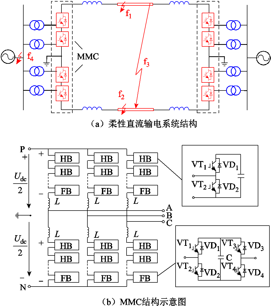
图1 系统结构示意图
Fig.1 Flexible DC transmission system
柔性直流输电系统在结构上正负极严格对称,本文选正极故障为例进行详细分析。当系统发生正极接地故障时,整流侧输送功率如图2所示。其中 为整流侧交流电压,
 为整流侧正极桥臂电压,
 为整流侧正极桥臂等效电容,
 为整流侧正极桥臂电感、平波电抗器及线路等效电感,
 为整流侧正极桥臂、线路电阻及过渡电阻等效电阻,
 为整流侧第
为整流侧第 相正极桥臂输送功率,
 为故障后整流侧正极桥臂向线路传送的功率。
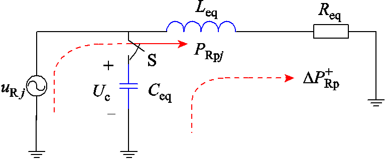
图2 正极故障下整流侧正极桥臂等效电路
Fig.2 Equivalent circuit of rectifier side positive pole upper bridge arm
在系统正常运行时,整流侧正极桥臂电容电压处于动态平衡状态,此时电容可以看作开路,即S处于开断状态,功率仅从整流侧交流系统向逆变侧转移,传输功率为 。当系统发生正极接地故障时,直流输电线路电压骤降为零,电容电压失去动态平衡,此时传输的功率为两部分叠加,一部分为整流侧正极桥臂交流系统向逆变侧输送的功率
 ;另一部分是由于整流侧正极桥臂电容电压高于输电线路电压,正极桥臂电容流向直流线路的功率
 ,两部分功率方向如图2所示。
发生正极接地故障后,S闭合,整流侧正极桥臂叠加电流为
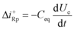 (1)
(1)
整流侧正极桥臂叠加回路电压为
 (2)
(2)
整流侧正极桥臂功率增量为
 (3)
(3)
在发生正极接地故障时,整流侧正极桥臂流过的功率 为
为
 (4)
(4)
由式(1)~式(4)分析可知,在系统发生正极接地故障时,整流侧正极桥臂电压高于线路电压,功率增量的传输方向与交流系统功率传输方向相同, 为正,即在发生正极接地故障时,整流侧正极桥臂功率增大。
在系统运行时,正极输电线路和负极输电线路之间存在互阻抗,互阻抗由两部分组成:一部分为输电线路和大地均为理想导体时正极输电线路和负极输电线路之间的互感 ;另一部分为正极输电线路和负极输电线路与大地构建通路而与大地形成的互阻抗
 。正负极输电线路间互阻抗为
 (5)
(5)
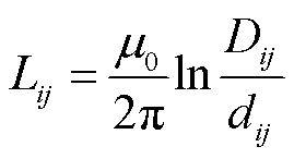 (6)
(6)
 (7)
(7)
式中, 为正负极输电线路间的距离;
 为正负极输电导线间的镜像距离;
 为输电导线磁导率。
当系统发生正极接地故障时,整流侧正极故障电流和故障电压会在负极形成耦合,耦合示意图如图3所示,耦合电感的同名端方向相反。
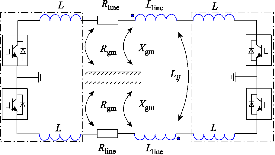
图3 整流侧正负极输电线路耦合示意图
Fig.3 Schematic diagram of positive and negative transmission line coupling on the rectifier side
整流侧负极桥臂耦合电流增量为
 (8)
(8)
整流侧负极桥臂耦合电压增量为
![]() (9)
(9)
整流侧负极桥臂功率增量为
 (10)
(10)
在发生正极接地故障时,整流侧负极桥臂流过的功率 为
为
 (11)
(11)
式中, 为电流耦合系数;
 为系统正常运行时整流侧j相负极桥臂交流系统向逆变侧输送的功率。
在发生正极接地故障时,能量流动桥臂电容电压 下降,
下降, ,由式(10)可知,
 为负,整流侧负极桥臂向逆变侧输送功率减小。
正极故障桥臂功率解析如图4所示。在发生正极故障后,系统交流电压缓慢跌落,交流电流经过20 ms左右逐渐增大;正极电压振荡跌落至零,负极电压经过短时振荡恢复至正常;正、负极电流增大。图4e~图4g中红色虚线分别表示A、B、C三相正极桥臂功率解析值,黑色实线分别表示A、B、C三相正极桥臂功率仿真值,对比可知,在发生正极接地故障时,解析值的幅值及振荡趋势与仿真值相同。由于柔性直流输电系统正负极对称,此处仅对正极故障进行验证。仿真算例参数见表1。
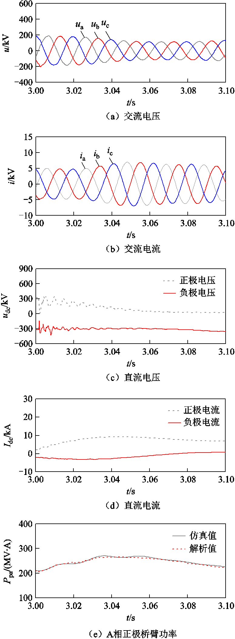
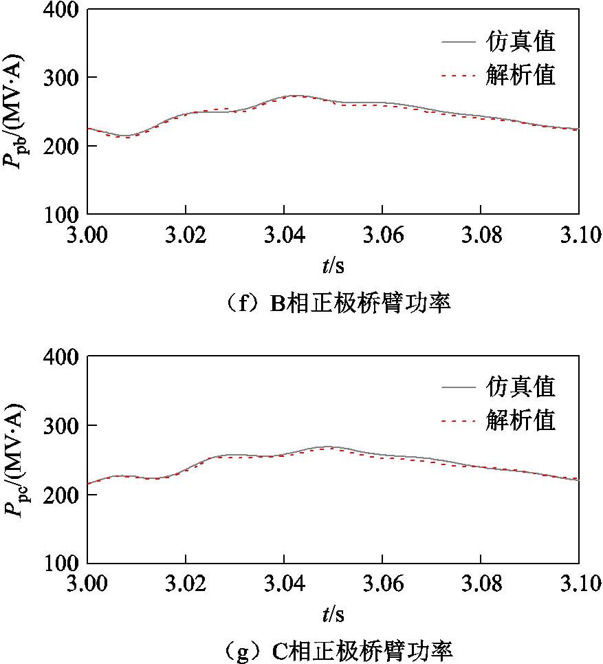
图4 正极故障桥臂功率解析
Fig.4 Analytical diagram of the bridge arm power of the positive pole to ground fault
表1 仿真算例参数
Tab.1 Simulation Study Parameters

参数数值 直流电压Uc/kV320 桥臂等效电阻/Ω0.003 8 桥臂等效电容Ceq/μF134.21 桥臂等效电感Leq/H0.05 过渡电阻/Ω0 线路等效电阻/(Ω/km)0.01
发生直流线路故障前后桥臂功率差值如图5所示。由图5可知,在发生直流线路故障时,故障后桥臂功率减去故障前桥臂功率差值为正,故障后桥臂功率增大。
综上所述,发生直流侧故障时桥臂功率呈现上升趋势。由此可利用桥臂功率变化特征构造柔性直流输电线路保护判据。
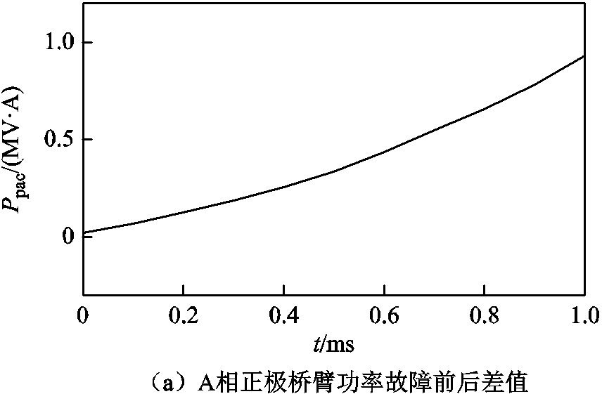
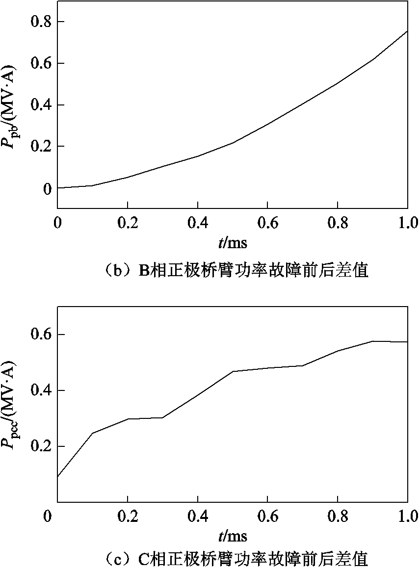
图5 故障前后桥臂功率差值
Fig.5 The power difference of the arm bridge before and after the fault
本文在对桥臂功率解析时忽略了一些影响因素,造成解析值与仿真值之间的误差,主要有:
(1)相间环流引起的误差。柔性直流输电系统运行时,由于换流阀中电容电压不平衡,会在换流阀桥臂之间形成相间环流,本文在分析时忽略了相间环流对桥臂功率的影响,对解析结果会产生一定的误差。
(2)换流阀功率器件损耗。未考虑系统运行时换流阀内部IGBT开关损耗及二极管的通态损耗,对解析结果造成一定误差。
桥臂功率误差分析示意图如图6所示,iarm为桥臂电流,icir为相间环流,Idc/3为相电流,其大小满足
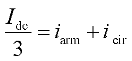 (12)
(12)
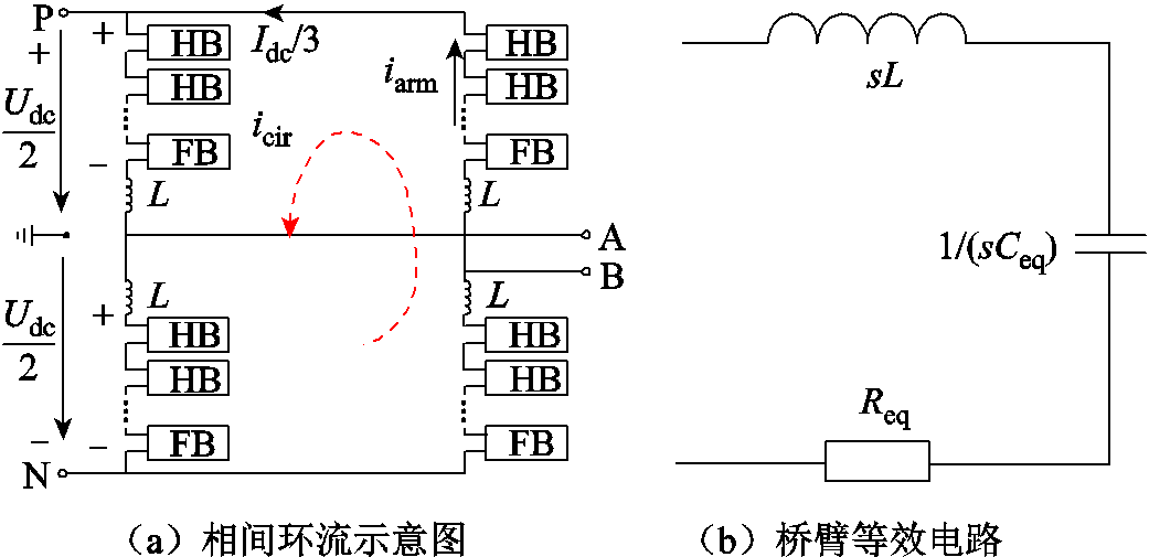
图6 桥臂功率误差分析示意图
Fig.6 Schematic diagram of bridge arm power error analysis
在计算时忽略了相间环流造成的损耗和功率器件损耗,相间环流造成的损耗计算表达式为
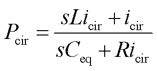 (13)
(13)
功率器件损耗表达式为
 (14)
(14)
式中,L为桥臂电感;R为桥臂功率器件等效电阻;s=jω。
本文模型中直流电流Idc为2 kA,桥臂电流为0.7 kA,相间环流为-0.3 kA,由表1可知,桥臂等效电阻为0.003 8 Ω,等效电容为134.21 mF,等效电感为0.05 H,根据式(12)~式(14)可得,环流损耗为0.52 MV∙A,功率器件损耗为0.37 MV∙A。其中,由于相间环流中主要成分为二倍频分量,频率为100 Hz,环流损耗中ω=628 rad/s;桥臂电流中为工频量,频率为50 Hz,功率器件损耗中ω=314 rad/s。
根据上述分析,当直流线路发生交流故障、直流线路故障及换流阀直流侧故障时,桥臂功率产生相应的变化,因此利用桥臂功率变化率构造启动判据为
式中, 为桥臂功率;
 与系统的采样频率
 有关,
有关, ;
; 为常数。为了兼顾启动判据的灵敏性与可靠性,判据需要持续成立一段时间才启动保护,本文选择持续时间为0.3 ms[31]。
实时采集故障前1 ms内臂功率数据 和与之对应的故障后1 ms内桥臂功率数据
 ,根据前述交流故障下、直流故障下桥臂功率的变化特征,构造保护判据为
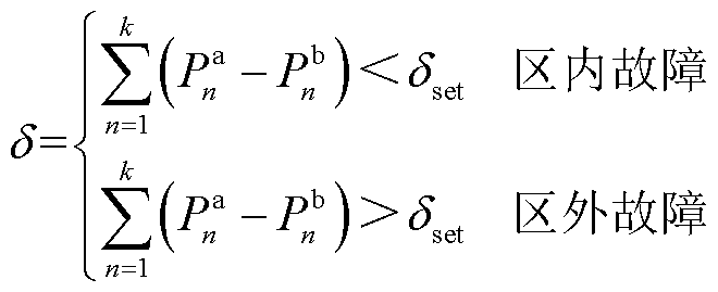 (16)
(16)
式中,k为1 ms内桥臂功率的采样点,本文系统仿真采样率为10 kHz,k取值为10; 取0即可。
取0即可。
取故障后1 ms内正、负极桥臂功率数据,分别记为 和
和 ,根据正、负极故障下桥臂功率变化特征,构造选极元件为
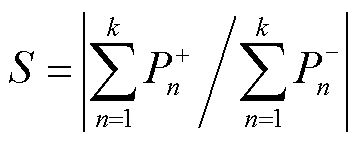 。
。
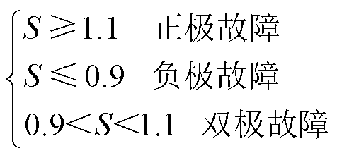 (17)
(17)
当发生双极故障时,阈值为1,上下留10%裕度,阈值取0.9和1.1。
采集故障前1 ms内和故障后1 ms内桥臂功率数据,取故障后前三个点,当满足 时,保护算法启动;进行过电流和低电压检测,判断故障是否真实存在;逐点采集故障后桥臂功率数据,计算并判断
 与
与 的关系,当
的关系,当 为区外故障,当
 为区内故障;全桥子模块进行负投入,开启故障自清除;计算
 ,当
,当 ,为正极故障,当
 为负极故障,当
 为双极故障。理论上,取
 即可,为了提高保护算法的可靠性,在此基础上留10%裕度。保护方案流程如图7所示。
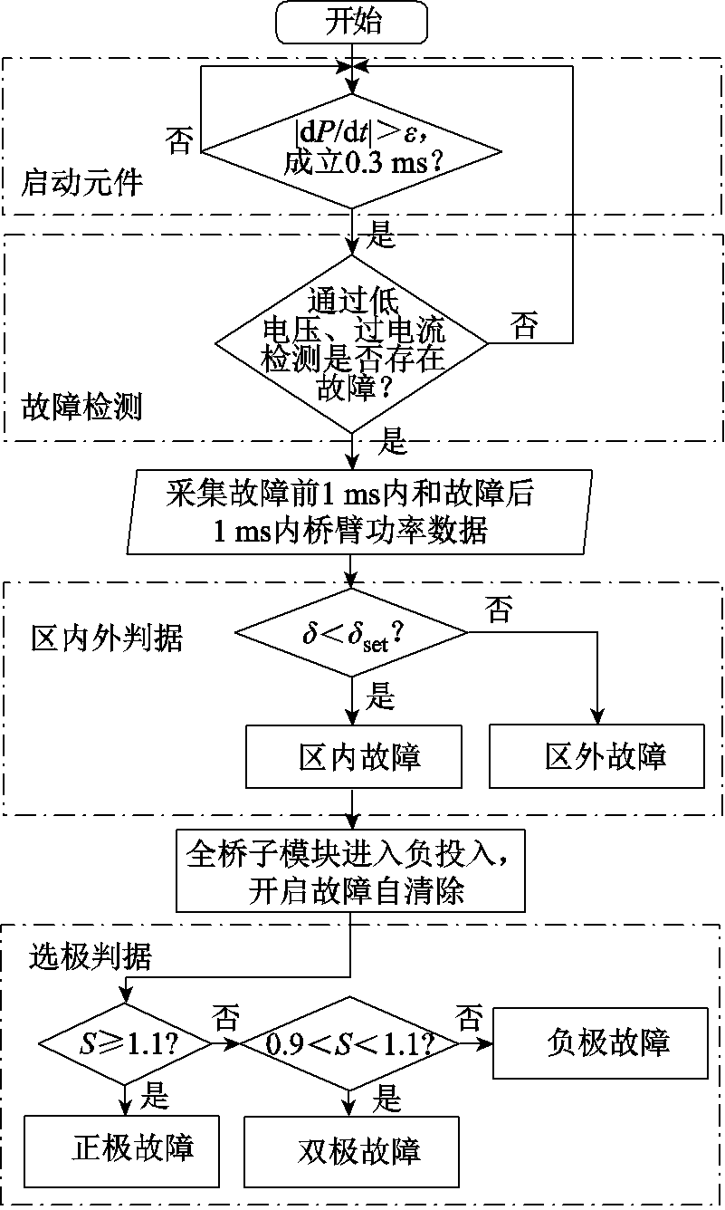
图7 保护方案流程
Fig.7 Protection scheme flow chart
在RTDS平台搭建了基于全-半混合的MMC双端真双极柔性直流输电系统,该系统采用架空线传输方式,输电距离为500 km,输电线路采用的分布参数线路模型为频变模型,输电容量为1 280 MW,故障发生时刻为3 s,仿真步长为2 ms,采样步长为100 ms,采样频率为10 kHz,保护中断时间为0.7 ms。详细系统参数见表2。RTDS实验平台如图8所示。
表2 基于MMC的双端真双极柔性直流输电系统参数
Tab.2 The parameter of MMC-based two-terminal true bipolar flexible HVDC transmission system

参数数值 交流电压/kV175 直流电流/kA2 直流电压/kV320 输送容量/MW1 280 线路长度/km500 全桥子模块数120 半桥子模块数32
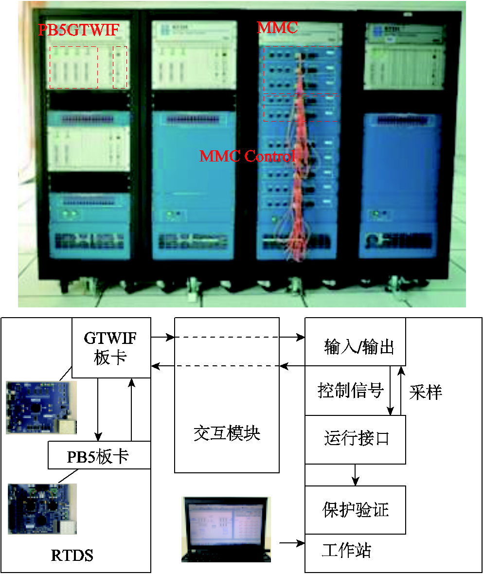
图8 RTDS实验平台
Fig.8 The RTDS experimental platform
不同故障类型判别结果见表3,过渡电阻为0.01 Ω,直流故障距离为100 km。由表3可知,发生交流故障时, ,判断为区外故障;发生直流故障时,
 ,判断为区内故障;在发生正极故障时,
 ,在发生负极故障时,
 ,在发生极间故障时,
 ,满足选极判据条件。本文所提保护方法,在不同故障类型下都能够正确识别故障并选极。
表3 不同故障类型判别结果
Tab.3 The results of different fault types

故障类型判断结果 整流侧单相故障6.63—区外故障 整流侧两相故障28.69—区外故障 整流侧三相故障13.35—区外故障 逆变侧单相故障0.99—区外故障 逆变侧两相故障0.81—区外故障 逆变侧三相故障0.59—区外故障 正极故障-754.5428.85正极故障 负极故障-747.120.046负极故障 极间故障-884.531.02极间故障
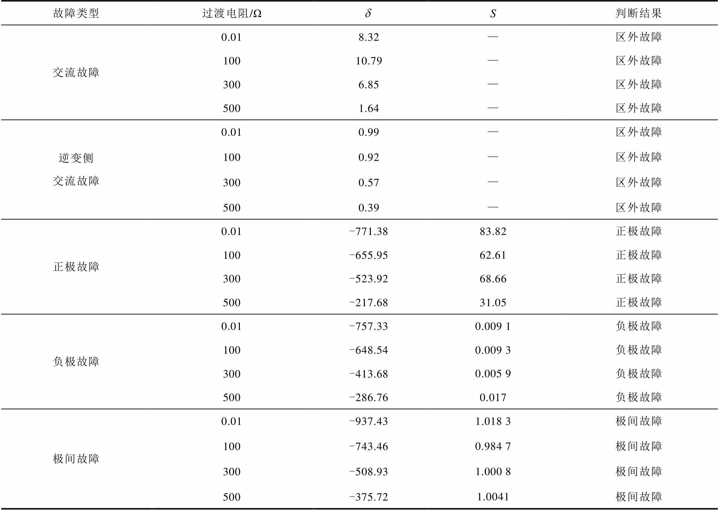
表4为在过渡电阻分别为0.01 Ω、100 Ω、300 Ω及500 Ω下发生交流单相故障、交流两相故障、交流三相故障下的判断结果,以及故障距离为150 km,过渡电阻分别为0.01 Ω、100 Ω、300 Ω及500 Ω下直流正极故障、负极故障和极间故障下的判断结果。由表4可知,在过渡电阻分别为0.01 Ω、100 Ω、300 Ω及500 Ω下,发生交流故障时, ,判断为区外故障;发生直流故障时,
 ,判断为区内故障。在过渡电阻分别为0.01 Ω、100 Ω、300 Ω及500 Ω下,发生正极故障时,
 ,在发生负极故障时,
 ,在发生极间故障时,
 ,满足选极判据条件。从而验证了本文所提保护方法,在交流系统高阻故障和直流高阻故障下都能够正确识别故障并选极。
表4 不同过渡电阻判别结果
Tab.4 The results of different transition resistance
故障类型过渡电阻/ΩS判断结果 交流故障0.018.32—区外故障 10010.79—区外故障 3006.85—区外故障 5001.64—区外故障 逆变侧交流故障0.010.99—区外故障 1000.92—区外故障 3000.57—区外故障 5000.39—区外故障 正极故障0.01-771.3883.82正极故障 100-655.9562.61正极故障 300-523.9268.66正极故障 500-217.6831.05正极故障 负极故障0.01-757.330.009 1负极故障 100-648.540.009 3负极故障 300-413.680.005 9负极故障 500-286.760.017负极故障 极间故障0.01-937.431.018 3极间故障 100-743.460.984 7极间故障 300-508.931.000 8极间故障 500-375.721.0041极间故障
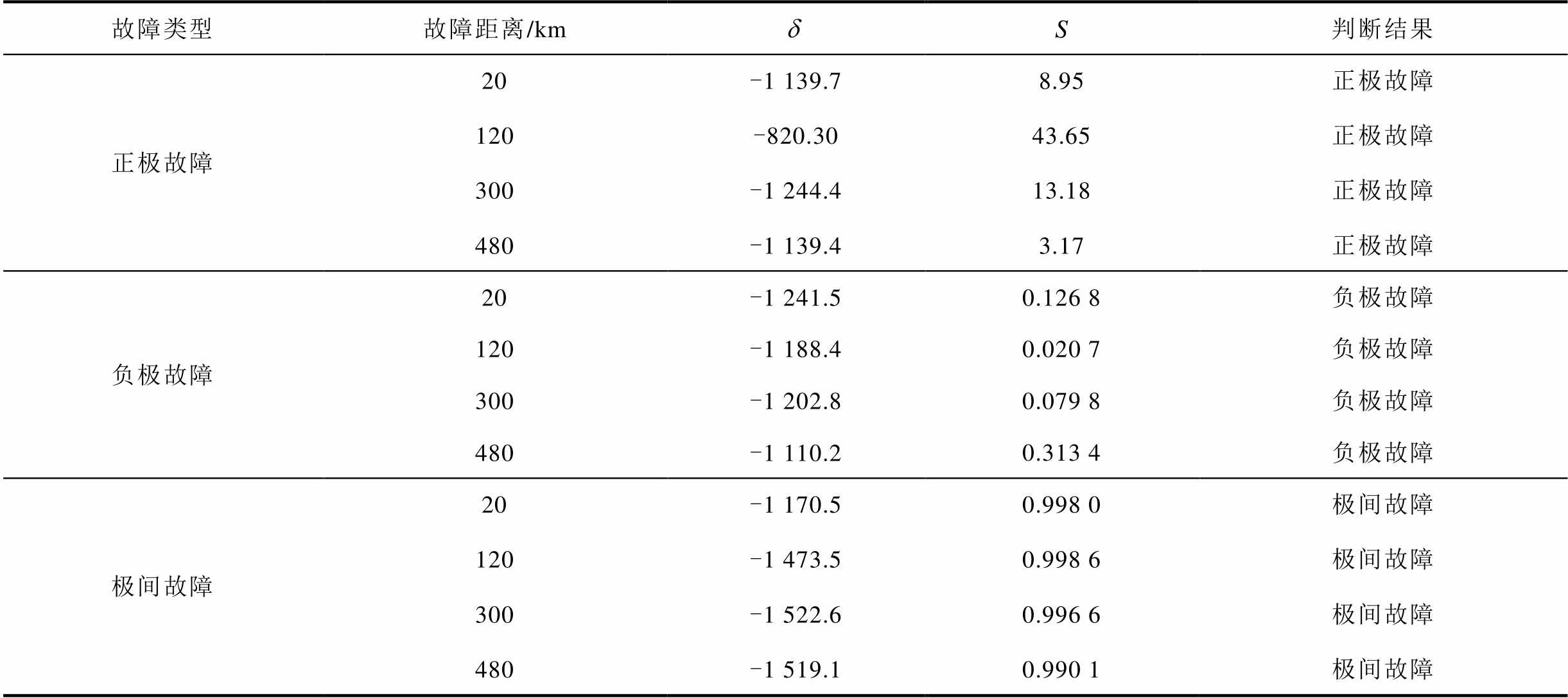
在故障距离分别为20 km、120 km、300 km及480 km下发生直流正极故障、负极故障和极间故障时的判断结果见表5。由表5可知,在故障距离分别为20 km、120 km、300 km及480 km下,发生交流故障时, ,判断为区外故障;发生直流故障时,
 ,判断为区内故障。在故障距离分别为20 km、120 km、300 km及480 km下,发生正极故障时,
 ;发生负极故障时,
 ;发生极间故障时,
 ,满足选极判据条件。从而验证了本文所提保护方法在交流系统高阻故障和直流高阻故障下都能够正确识别故障并选极。
表5 不同故障距离判别结果
Tab.5 The results of different fault distance
故障类型故障距离/kmS判断结果 正极故障20-1 139.78.95正极故障 120-820.3043.65正极故障 300-1 244.413.18正极故障 480-1 139.43.17正极故障 负极故障20-1 241.50.126 8负极故障 120-1 188.40.020 7负极故障 300-1 202.80.079 8负极故障 480-1 110.20.313 4负极故障 极间故障20-1 170.50.998 0极间故障 120-1 473.50.998 6极间故障 300-1 522.60.996 6极间故障 480-1 519.10.990 1极间故障
噪声干扰会对保护方法造成较大影响。为了验证本文所提方法具有较好的抗噪声干扰能力,在故障信号中分别加入10 dB、20 dB、30 dB和40 dB高斯白噪声进行分析,判断结果见表6。
表6 不同信噪比下的判断结果
Tab.6 The results of different SNRs

故障类型过渡电阻/Ω故障距离/kmS10 dB20 dB30 dB40 dB判断结果 SSSS 整流侧交流故障0.01—8.32—8.04—7.18—8.31—8.32—区外故障 100—10.79—10.86—10.77—10.79—10.80—区外故障 300—6.85—7.04—6.80—6.84—6.85—区外故障 500—1.64—1.67—1.61—1.65—1.64—区外故障 逆变侧交流故障0.01—0.99—0.51—0.77—0.91—0.93—区外故障 100—0.92—0.82—0.85—0.90—0.92—区外故障 300—0.57—0.36—0.45—0.55—0.58—区外故障 500 Ω—0.39—0.58—0.51—0.48—0.39—区外故障 正极故障0.0120-1 139.78.95-1 138.09.10-1 129.98.94-1 139.88.96-1 139.78.95正极故障 0.01120-820.343.65-819.446.90-820.842.34-820.443.64-820.343.69正极故障 0.01300-1 244.413.18-1 245.113.37-1 244.213.17-1 244.413.15-1 244.413.18正极故障 0.01480-1 139.43.17-1 137.33.17-1 140.23.18-1 139.33.17-1 139.43.17正极故障 负极故障0.0120-1 241.50.126 8-1 141.50.127 6-1 141.90.126 6-1 141.40.126 9-1 241.60.126 7负极故障 0.01120-1 188.40.020 7-1 188.40.021 4-1 188.80.021 3-1 188.40.020 7-1 188.40.020 7负极故障 0.01300-1 202.80.079 8-1 200.70.080 6-1 202.60.080-1 202.70.079 8-1 202.90.079 9负极故障 0.01480-1 110.20.313 4-1 112.00.311 2-1 110.80.312 7-1 110.10.313 6-1 110.20.313 4负极故障 极间故障0.0120-1 170.50.998 0-1 170.90.996 2-1 169.50.998 9-1 170.40.997 7-1 170.60.997 8极间故障 0.01120-1 473.50.998 6-1 471.01.000 8-1 473.90.998 2-1 473.60.998 4-1 473.50.998 5极间故障 0.01300-1 522.60.996 6-1 521.50.997 6-1 522.10.997 0-1 522.40.996 8-1 522.60.996 6极间故障 0.01480-1 519.10.990 1-1 518.60.990 3-1 518.80.989 8-1 518.90.990 2-1 519.20.990 0极间故障
通过表6可知,在信噪比分别为10 dB、20 dB、30dB和40 dB下,本文提出的保护方法在不同故障类型和不同故障距离下都具有较好的适应性,能够正确地识别区内外故障及故障极。
实际在运工程主保护较多采用ABB公司的单端行波保护原理,利用文献[32-33]中行波原理保护方案与本文所提方案进行对比,见表7。
表7 本文方法与文献[32-33]方法对比
Tab.7 Comparison between the proposed protection scheme and the protection scheme in Ref.[32-33]

过渡电阻/ΩABB行波保护文献[33]保护方案本文所提保护 0.01√√√ 100√√√ 300×√√ 500××√
ABB行波保护方案在过渡电阻为300 Ω时出现误动。文献[32]指出,ABB行波保护在整流侧的耐受临界电阻为173 Ω,通过表7可知,本文所提保护方案相比于ABB行波保护方案,具有更好的耐过渡电阻能力和可靠性。
为了验证本文所提方案具有更好的耐过渡电阻能力和抗干扰能力,与文献[2, 14, 34-35]所提保护方法进行对比,结果见表8。文献[34]提出一种基于故障电压梯度的时域保护方案,文献[35]提出一种基于故障电流频率特征的频域保护方案。
通过表8可知,基于故障电压梯度的时域保护方案和基于故障电流频率特征的频域保护方案耐过渡电阻为200 Ω及以下,本文所提方案耐过渡电阻达500 Ω,对比可知本文所提保护方案具有更好的耐过渡电阻能力。
为了验证本文所提保护方案具有良好的抗干扰能力,分别加入信噪比为10~40 dB高斯白噪声,对比结果见表9。通过表9可知,基于故障电压梯度的时域保护方案和基于故障电流频率特征的频域保护方案能够抗30 dB和40 dB高斯白噪声,本文所提保护方案能够抗10~40 dB高斯白噪声。通过对比可知,本文所提保护方案具有更强的抗干扰能力。
表8 本文方法与文献[2, 14, 34-35]方法耐过渡电阻对比
Tab.8 Comparison between the proposed protection scheme and the protection scheme in Ref.[2, 14, 34-35] on response to transition resistance

过渡电阻/Ω文献[2]保护方案文献[14]保护方案文献[34]保护方案文献[35]保护方案本文所提保护方案 0.01√√√√√ 100√√√√√ 200√√√√√ 300√√√√√ 500××××√
表9 本文方法与文献[2, 14, 34-35]方法抗干扰能力对比
Tab.9 Comparison between the proposed protection scheme and the protection scheme in Ref.[2, 14, 34-35] on anti-interference ability

信噪比/ dB文献[2]保护方案文献[14]保护方案文献[34]保护方案文献[35]保护方案本文所提保护方案 10××××√ 20×√××√ 30√√√√√ 40√√√√√
本文基于能量观点对全-半混合型柔性直流输电系统在直流线路故障下桥臂功率特征进行了分析,提出基于桥臂功率特征的全-半混合性柔性直流输电系统保护方案。得到结论如下:
1)当系统发生直流线路故障时,桥臂电容向直流侧故障点放电,且桥臂电容放电方向与原系统电流方向相同,桥臂功率上升。
2)利用直流线路故障下桥臂功率特征构造保护,方案简单,能够可靠识别直流线路故障,选择性高、快速性好,满足全-半混合性柔性直流输电保护要求。
3)通过与传统时域方法和频域方法对比,验证了该保护方案具有更强的耐过渡电阻能力以及抗干扰能力,可靠性高。
参考文献
[1] 陈皓勇. “双碳”目标下的电能价值分析与市场机制设计[J]. 发电技术, 2021, 42(2): 141-150. Chen Haoyong. Electricity value analysis and market mechanism design under carbon-neutral goal[J]. Power Generation Technology, 2021, 42(2): 141-150.
[2] 束洪春, 代月, 安娜, 等. 基于交叉重叠差分变换的MMC-HVDC线路故障识别方法[J]. 电工技术学报, 2021, 36(1): 203-214, 226. Shu Hongchun, Dai Yue, An Na, et al. Fault identification method of MMC-HVDC line based on sequential overlapping derivative transform[J]. Transactions of China Electrotechnical Society, 2021, 36(1): 203-214, 226.
[3] 汤广福, 贺之渊, 庞辉. 柔性直流输电工程技术研究、应用及发展[J]. 电力系统自动化, 2013, 37(15): 3-14. Tang Guangfu, He Zhiyuan, Pang Hui. Research, application and development of VSC-HVDC engineering technology[J]. Automation of Electric Power Systems, 2013, 37(15): 3-14.
[4] 周家培, 赵成勇, 李承昱, 等. 基于直流电抗器电压的多端柔性直流电网边界保护方案[J]. 电力系统自动化, 2017, 41(19): 89-94, 146. Zhou Jiapei, Zhao Chengyong, Li Chengyu, et al. Boundary protection scheme for multi-terminal flexible DC grid based on voltage of DC reactor[J]. Automation of Electric Power Systems, 2017, 41(19): 89-94, 146.
[5] 安娜, 束洪春, 郭瑜, 等. 基于感性模糊识别的MMC直流输电线路单极接地故障分析[J]. 电力自动化设备, 2021, 41(3): 71-77. An Na, Shu Hongchun, Guo Yu, et al. Single pole-to-ground fault analysis of MMC DC transmission lines based on inductance fuzzy identification[J]. Electric Power Automation Equipment, 2021, 41(3): 71-77.
[6] 陈继开, 孙川, 李国庆, 等. 双极MMC-HVDC系统直流故障特性研究[J]. 电工技术学报, 2017, 32(10): 53-60, 68. Chen Jikai, Sun Chuan, Li Guoqing, et al. Study on characteristics of DC fault in bipolar MMC-HVDC system[J]. Transactions of China Electrotechnical Society, 2017, 32(10): 53-60, 68.
[7] 陈剑, 杜文娟, 王海风. 基于对抗式迁移学习的含柔性高压直流输电的风电系统次同步振荡源定位[J]. 电工技术学报, 2021, 36(22): 4703-4715. Chen Jian, Du Wenjuan, Wang Haifeng. Location method of subsynchronous oscillation source in wind power system with VSC-HVDC based on adversarial transfer learning[J]. Transactions of China Electrotechnical Society, 2021, 36(22): 4703-4715.
[8] 姚良忠, 吴婧, 王志冰, 等. 未来高压直流电网发展形态分析[J]. 中国电机工程学报, 2014, 34(34): 6007-6020. Yao Liangzhong, Wu Jing, Wang Zhibing, et al. Pattern analysis of future HVDC grid development[J]. Proceedings of the CSEE, 2014, 34(34): 6007-6020.
[9] Tang Guangfu, He Zhiyuan, Pang Hui, et al. Basic topology and key devices of the five-terminal DC grid[J]. CSEE Journal of Power and Energy Systems, 2015, 1(2): 22-35.
[10] Li Bin, He Jiawei, Tian Jie, et al. DC fault analysis for modular multilevel converter-based system[J]. Journal of Modern Power Systems and Clean Energy, 2017, 5(2): 275-282.
[11] 付华, 陈浩轩, 李秀菊, 等. 含边界元件的MMC-MTDC直流侧单端量故障辨识方法[J]. 电工技术学报, 2021, 36(1): 215-226. Fu Hua, Chen Haoxuan, Li Xiuju, et al. MMC-MTDC DC side single-ended quantity fault identification method with boundary elements[J]. Transactions of China Electrotechnical Society, 2021, 36(1): 215-226.
[12] 魏晓光, 周万迪, 张升, 等. 模块化混合式高压直流断路器研究与应用[J]. 中国电机工程学报, 2020, 40(6): 2038-2046. Wei Xiaoguang, Zhou Wandi, Zhang Sheng, et al. Research and application of modular hybrid high voltage DC circuit breaker[J]. Proceedings of the CSEE, 2020, 40(6): 2038-2046.
[13] 熊岩, 饶宏, 许树楷, 等. 特高压多端混合直流输电系统启动与故障穿越研究[J]. 全球能源互联网, 2018, 1(4): 478-486. Xiong Yan, Rao Hong, Xu Shukai, et al. Research on start and fault ride-through strategy for ultra-high voltage multi-terminal hybrid DC transmission system[J]. Journal of Global Energy Interconnection, 2018, 1(4): 478-486.
[14] Shu Hongchun, Wang Guangxue, Tian Xincui, et al. Single-ended protection method of MMC-HVDC transmission line based on random matrix theory[J]. International Journal of Electrical Power & Energy Systems, 2022, 142: 108299.
[15] 曹润彬, 李岩, 许树楷, 等. 特高压混合多端直流线路保护配置与配合研究[J]. 南方电网技术, 2018, 12(11): 52-58, 83. Cao Runbin, Li Yan, Xu Shukai, et al. Research on configuration and coordination of multi-terminal hybrid UHVDC line protection[J]. Southern Power System Technology, 2018, 12(11): 52-58, 83.
[16] Fletcher S D A, Norman P J, Fong K, et al. High-speed differential protection for smart DC distribution systems[J]. IEEE Transactions on Smart Grid, 2014, 5(5): 2610-2617.
[17] 宋国兵, 蔡新雷, 高淑萍, 等. VSC-HVDC频变参数电缆线路电流差动保护新原理[J]. 中国电机工程学报, 2011, 31(22): 105-111. Song Guobing, Cai Xinlei, Gao Shuping, et al. Novel Current differential protection principle of VSC-HVDC considering frequency-dependent characteristic of cable line[J]. Proceedings of the CSEE, 2011, 31(22): 105-111.
[18] Zheng Xiaodong, Tai Nengling, Thorp J S, et al. Improved differential protection scheme for long distance UHVDC transmission line[C]//2014 IEEE PES General Meeting | Conference & Exposition, National Harbor, MD, USA: 1-5.
[19] Sneath J, Rajapakse A D. Fault detection and interruption in an earthed HVDC grid using ROCOV and hybrid DC breakers[J]. IEEE Transactions on Power Delivery, 2016, 31(3): 973-981.
[20] 戴志辉, 刘宁宁, 何永兴, 等. 基于直流滤波环节暂态能量比的高压直流线路纵联保护[J]. 电工技术学报, 2020, 35(9): 1985-1998. Dai Zhihui, Liu Ningning, He Yongxing, et al. A pilot protection for HVDC transmission lines based on the ratio of DC filter link transient energy[J]. Transactions of China Electrotechnical Society, 2020, 35(9): 1985-1998.
[21] 李爱民, 蔡泽祥, 李晓华. 直流线路行波传播特性的解析[J]. 中国电机工程学报, 2010, 30(25): 94-100. Li Aimin, Cai Zexiang, Li Xiaohua. Study on the propagation characteristics of traveling waves in HVDC transmission lines on the basis of analytical method[J]. Proceedings of the CSEE, 2010, 30(25): 94-100.
[22] 甄永赞, 苏宁赛, 杨荆宜. 直流输电线路极波变化率保护的拓展方法研究[J]. 中国电机工程学报, 2021, 41(15): 5212-5220. Zhen Yongzan, Su Ningsai, Yang Jingyi. Research on extension method of polar wave change rate protection for HVDC transmission line[J]. Proceedings of the CSEE, 2021, 41(15): 5212-5220.
[23] 郑伟, 武霁阳, 李海锋, 等. 特高压直流线路自适应行波保护[J]. 电网技术, 2015, 39(7): 1995-2001. Zheng Wei, Wu Jiyang, Li Haifeng, et al. Research on adaptive travelling wave based protection for UHVDC transmission line[J]. Power System Technology, 2015, 39(7): 1995-2001.
[24] 张冰, 赵书强, 甄永赞. 柔性直流输电的改进行波保护仿真研究[J]. 电力系统保护与控制, 2017, 45(16): 58-63. Zhang Bing, Zhao Shuqiang, Zhen Yongzan. Simulation study of an improved traveling wave protection for VSC-HVDC transmission system[J]. Power System Protection and Control, 2017, 45(16): 58-63.
[25] 汤广福, 王高勇, 贺之渊, 等. 张北500 kV直流电网关键技术与设备研究[J]. 高电压技术, 2018, 44(7): 2097-2106. Tang Guangfu, Wang Gaoyong, He Zhiyuan, et al. Research on key technology and equipment for Zhangbei 500 kV DC grid[J]. High Voltage Engineering, 2018, 44(7): 2097-2106.
[26] 戴志辉, 刘自强, 杨明玉, 等. 基于暂态行波幅值积分的柔性直流电网纵联保护[J]. 中国电机工程学报, 2020, 40(20): 6578-6592. Dai Zhihui, Liu Ziqiang, Yang Mingyu, et al. Pilot protection for flexible DC grids based on amplitude integral of transient wavelet[J]. Proceedings of the CSEE, 2020, 40(20): 6578-6592.
[27] 童宁, 林湘宁, 张雪松, 等. 不依赖于边界元件的架空型多端柔直电网就地测距式接地保护原理[J]. 中国电机工程学报, 2019, 39(7): 2049-2060. Tong Ning, Lin Xiangning, Zhang Xuesong, et al. Fault location based single-ended protection strategy for overhead VSC-MTDC independent on boundary component[J]. Proceedings of the CSEE, 2019, 39(7): 2049-2060.
[28] 梁远升, 黄泽杰, 李海锋, 等. 基于行波相位特性的三端混合直流线路行波保护原理[J]. 中国电机工程学报, 2021, 41(13): 4525-4542. Liang Yuansheng, Huang Zejie, Li Haifeng, et al. Phase characteristics based travelling wave protection for transmission line of three-terminal hybrid HVDC system[J]. Proceedings of the CSEE, 2021, 41(13): 4525-4542.
[29] 徐雨哲, 徐政, 张哲任, 等. 基于LCC和混合型MMC的混合直流输电系统控制策略[J]. 广东电力, 2018, 31(9): 13-25. Xu Yuzhe, Xu Zheng, Zhang Zheren, et al. Control strategy for hybrid HVDC transmission system based on LCC and hybrid MMC[J]. Guangdong Electric Power, 2018, 31(9): 13-25.
[30] 田培涛, 吴庆范, 黄金海, 等. 基于LCC和FHMMC的混合多端直流系统线路保护方案研究[J]. 电力系统保护与控制, 2021, 49(1): 170-177. Tian Peitao, Wu Qingfan, Huang Jinhai, et al. Research on protection strategy of a hybrid multi-terminal DC system based on LCC and FHMMC[J]. Power System Protection and Control, 2021, 49(1): 170-177.
[31] 祝新驰, 李海锋, 黄炟超, 等. 基于触发角变化特性的高压直流线路纵联保护[J]. 电力自动化设备, 2020, 40(6): 163-171. Zhu Xinchi, Li Haifeng, Huang Dachao, et al. Pilot protection of HVDC power transmission lines based on variation characteristics of firing angle[J]. Electric Power Automation Equipment, 2020, 40(6): 163-171.
[32] 郑伟, 张楠, 杨光源. 西门子及ABB直流线路行波保护对比和改进研究[J]. 电力系统保护与控制, 2015, 43(24): 149-154. Zheng Wei, Zhang Nan, Yang Guangyuan. Comparative and improvement investigation on the DC transmission line traveling wave protections of Siemens and ABB[J]. Power System Protection and Control, 2015, 43(24): 149-154.
[33] Zheng Yuping, He Jiawei, Li Bin. et al. Research on DC protection strategy in multi-terminal hybrid HVDC system[J]. Engineering, 2021, 7(8): 65-88.
[34] Liu Xiaolei, Osman A H, Malik O P. Hybrid traveling wave/boundary protection for monopolar HVDC line[J]. IEEE Transactions on Power Delivery, 2009, 24(2): 569-578.
[35] Li Rui, Xu Lie, Yao Liangzhong. DC fault detection and location in meshed multiterminal HVDC systems based on DC reactor voltage change rate[J]. IEEE Transactions on Power Delivery, 2017, 32(3): 1516-1526.
Abstract The "Carbon-Neutral" goal is the main driving force to build a new power system with renewable energy. Due to the advantages of low loss and no commutation failure, the voltage source converter (VSC) transmission based on modular multilevel converter (MMC) has been widely used in large-scale renewable energy grid-connected power transmission. When the DC line faults, the fault current increase rapidly, causing irreversible damage to power electronic power devices and even paralysis of the transmission system. It brings a serious crisis to the safe operation of the power grid. Therefore, fast and selective identification of DC line faults is one of the key technologies to be solved urgently. The protection research of the VSC-HVDC transmission system based on full-half hybrid sub-modular structure is of great significance to the large capacity transmission of renewable energy.
Firstly, the bridge arm power calculation circuit is equivalent when the DC line is faulted, and the change characteristics of the bridge arm power under the DC line fault are analyzed. When the DC line faults, the bridge arm power increases. Then, the bridge arm power under DC fault is numerically analyzed, and the causes of errors are analyzed in detail. Finally, based on the power characteristics of the bridge arm, the protection scheme of the DC transmission line is proposed, the set-up element, the identification element of internal and external fault, and the faulty poles detection element are constructed, and the complete protection flow chart is given.
A double-ended true bipolar full-half hybrid MMC-HVDC transmission system is built on the RTDS platform. The system adopts the overhead line, the transmission distance is 500 km, and the transmission line adopts the frequency-variable model, and the transmission capacity is 1 280 MW, the fault occurrence time is 3 s, the simulation step is 2 μs, the sampling step is 100 μs, the sampling frequency is 10 kHz, and the protection interruption time is 0.7 ms. Firstly, the protection effect under different fault types is verified. When an AC fault occurs,  , it is judged as an external fault. When a DC fault occurs,
  , it is judged as an internal fault. When a positive fault occurs,
  , when a negative fault occurs,
  . When a pole-to-pole fault occurs,
  , which satisfies the pole detection criterion. The protection method proposed in this paper can correctly identify the fault and select the faulty poles under different fault types. Then the protection effect under different transition resistances and distance is verified. When the transition resistances are 0.01 Ω, 100 Ω, 300 Ω and 500 Ω, the fault distance are 20 km, 120 km, 300 km and 480 km, respectively. When a positive fault, a negative fault, and a pole-to-pole fault occurs, the internal/external fault identification criteria and pole selection criterion is satisfied. Furthermore, the anti-interference ability of the protection scheme is verified. And compared with the existing protection methods, the protection scheme has strong ability to response to the high transition resistance and noise interference.
Based on the energy point, this paper analyzes the bridge arm power characteristics of the VSC -HVDC transmission system under DC line faults, proposes a protection scheme of this VSC -HVDC transmission system based on the bridge arm power characteristics. The conclusion can be drawn as follows: (1) When a DC line faults, the bridge arm capacitor discharges to the fault point on the DC side, and the fault current direction is the same as the current direction of the original system. Therefore, when the DC line faults, the bridge arm power increases. (2) The protection scheme is constructed by using the bridge arm power characteristics. The scheme is simple, and it can reliably identify the DC line fault. (3) Compared with the traditional time domain and frequency domain method, it is verified that the protection scheme proposed is highly reliable, selective, and sensitive, has strong ability to response to the high transition resistance and noise interference.
Keywords:Full-half hybrid, voltage source converter based high voltage direct current (VSC-HVDC), equivalent circuit, bridge arm power characteristics, DC line protection
国家自然科学基金重点项目(52037003)和云南省重大科技专项计划项目(202002AF080001)资助。
收稿日期 2022-04-27
改稿日期 2022-07-21
DOI:10.19595/j.cnki.1000-6753.tces.220664
中图分类号:TM721.1; TM773
雷顺广 男,1995年生,博士研究生,研究方向为高压直流输电保护控制与故障测距。E-mail:leishunguang@hit.edu.cn(通信作者)
束洪春 男,1961年生,教授,博士生导师,研究方向为新型继电保护与故障测距、数字信号处理及其应用。E-mail:kmshc@sina.com
(编辑 赫蕾)