摘要 海洋核动力平台发电机拟采用有源电压消弧技术,需要实现全定子绕组内准确可靠的在线接地故障定位。针对现有基波定位方法存在的问题,该文提出一种基于三次谐波电势分布特征的发电机接地故障定位方法。基于各线圈三次谐波相电势180°相带分布特点,构建三次谐波故障电势与三次谐波相电势间的几何关系式。以三次谐波故障电流为中间量,建立包含三次谐波故障电势、中性点三次谐波电压、中性点三次谐波电压变化量的解析定位方程。方程中不含接地过渡电阻,适用于未安装注入式保护设备的海洋核动力平台发电机。在工程应用中,该方法可与基波定位方法协同配合,解决基波定位方法的多解问题,并提高定位结果精度。仿真和动模试验结果验证了所提定位方法的准确性和有效性。
关键词:海洋核动力平台 发电机定子绕组 接地故障定位 三次谐波 相带分布特点
海洋核动力平台长期运行于潮湿、盐雾的海洋环境中[1-2],系统内各主设备受腐蚀情况严重,发电机定子绕组接地故障频发[3-4]。为避免发电机盲目快速切机导致核反应堆负荷失电[5-8],海洋核动力平台拟采用有源电压消弧技术实现发电机定子接地故障消弧,在可靠转移负荷前实现主动降压不停电[9]。发电机有源电压消弧技术与配电网有源电压消弧技术[10]的不同之处在于,对于定子绕组不同位置的接地故障,需要外加的电压量不同。因此在发生定子绕组接地故障后,首先应实现可靠的接地故障定位,从而计算补偿电压。
发电机接地故障定位方法根据机组是否含注入式保护设备分为两类,其主要区别在于低频注入式保护设备能够在线测量接地过渡电阻[11]。文献[12]基于接地过渡电阻计算结果,利用故障位置与发电机零序电压、故障相相电压、对地电容以及接地故障过渡电阻之间的关系,计算出具体的故障位置。该方法原理简单,但无法适用于未安装注入式保护设备的海洋核动力平台发电机中。目前已有多篇文献针对接地过渡电阻无法通过外加低频量进行测量的情况进行讨论,并提出相应的故障定位方法。其中,文献[13-14]认为基波故障电势与基波故障相电势同相位,且幅值呈线性关系。基于基波零序电压、基波故障电势、故障点基波对地电压间满足的KVL方程构建定位方程,在无需注入式保护设备的条件下实现故障定位。然而,汽轮发电机定子绕组基波电势满足60°相带分布关系[15],故障电势与故障相电势间相位不等,上述近似处理方式将导致一定的理论误差。
在考虑发电机定子绕组电势分布特征条件下,文献[16]给出不同匝数处发生接地故障时故障电势的幅值和相位,通过查表法定位故障线圈。受负荷去磁作用和发电机励磁调节影响,负载变化时发电机相电势幅值和相位会发生变化,该方法难以适应不同运行工况。文献[17]在分析基波电势的相位分布特征时,认为故障电势在故障相电势上的投影呈线性分布,但由于各匝线圈相位不等,该方法仍存在理论误差。文献[18]基于基波电势相带分布特征,推导出基波零序电压和基波故障电势间满足的轨迹圆弧关系,并基于轨迹圆弧确定故障位置。文献[19]基于定子绕组60°相带分布特征,给出更加精确的故障相电势和故障绕组电势之间的幅值相位关系,并结合基波零序电压与基波故障电势间的KVL方程,提出一种解析定位方法。上述方法均基于基波电势实现接地故障定位,在中性点附近发生接地故障时,基波零序电压幅值较小,将产生较大的定位误差。此外,若仅利用基波零序电压实现定位,某些故障场景下会产生定位多解现象[18]。
针对发电机有源电压消弧技术对全定子绕组接地故障定位精度的要求,本文提出基于三次谐波电势分布特征的发电机定子绕组接地故障定位方法。基于发电机定子绕组三次谐波电势180°相带分布特点,构建三次谐波故障电势与三次谐波相电势间的几何关系。并以三次谐波故障电流为中间量,构建包含三次谐波故障电势、中性点三次谐波电压、中性点三次谐波电压变化量的解析定位方程。方程中不含接地过渡电阻,适用于未安装注入式保护设备的海洋核动力平台发电机。仿真和动模试验结果验证了所提定位方法的准确性和有效性,该方法能够克服现有基波定位方法的多解问题,在工程应用中可与基波定位方法协同配合,消除基波定位方法在中性点附近的定位死区。
海洋核动力平台发电机为汽轮发电机,其定子绕组的连接及分布采用60°相带方式,各匝线圈基波电势满足60°相带分布特点。对于三次谐波,所有匝线圈电势构成一个半圆,即![]() 相带[20],各匝电势幅值相等,但相位不同。
相带[20],各匝电势幅值相等,但相位不同。
海洋核动力平台发电机未安装低频注入式保护装置,无法通过低频测量量实现接地故障定位和接地过渡电阻的在线计算。目前,已有多篇文献基于基波故障特征量,针对无低频注入式发电机的接地故障在线定位方法进行讨论。此类方法包含的变量为故障点与发电机中性点间绕组匝数与完整故障分支绕组匝数之比α和接地过渡电阻阻值Rg,通过在线测量故障后的基波零序电压UN1构造故障定位方程为
 (1)
(1)
海洋核动力平台发电机采用中性点经高阻接地方式,基于KVL,中性点基波零序电压UN1、故障点基波电压、基波故障电势Ef1间满足
 (2)
(2)
式中,RN为中性点接地电阻;![]() 为发电机三相定子绕组对地电容与外接直连系统三相对地电容之和。根据式(2)得
为发电机三相定子绕组对地电容与外接直连系统三相对地电容之和。根据式(2)得
 (3)
(3)
式中,Ef1仅与α有关。海洋核动力平台发电机定子绕组采用60°相带分布形式,故障点f即相量Ef1的端点在60°相带对应的圆弧上。各相量间的几何关系如图1所示。
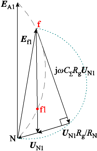
图1 发电机定子绕组单相接地故障定位多解示意图
Fig.1 Schematic diagram of the generator stator windings multiple location solutions under single-phase ground fault
图1中N为发电机中性点,当故障点位于f时,基波电势为Ef1。根据式(3),当Rg较大时,UN1幅值较小且Ef1与-UN1间的夹角较大。此时,如图1所示,在f1点,存在接地过渡电阻阻值为Rg1情况,中性点零序电压与f点发生接地过渡电阻为Rg时产生的UN1相同。因此,仅利用UN1进行接地故障定位时,在接地过渡电阻较大或故障点靠近中性点时,容易出现定位多解现象。
针对定位多解问题,文献[18]指出可利用低频注入式保护设备计算出的接地过渡电阻值确定Rg,从而唯一确定定位结果。但该方法仅适用于已经安装低频注入式设备的系统。文献[19]指出将多个定位解均作为备查结果。然而,在应用有源消弧技术时,需要唯一的定位结果以计算补偿电压。此外,在接地过渡电阻较大或故障点靠近发电机中性点时,基波零序电压幅值较小,此时受互感器测量误差影响,定位结果误差较大。
发电机相电势中包含基波和谐波分量,谐波分量以三次谐波为主。三次谐波含量在发电机电势中含量较高,目前也将三次谐波电量用于发电机定子接地保护[21-22]。此外,定子上任意点发生接地故障时,故障电流中均包含三次谐波分量,因此三次谐波电量可用于构建发电机接地故障定位方法。
发电机三次谐波电势满足180°相带分布形式[20]。以A相发生单相接地故障为例进行分析,故障分支三次谐波电势分布如图2所示。
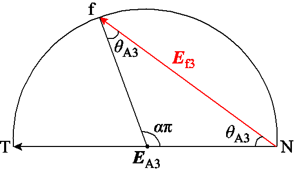
图2 故障分支三次谐波电势分布示意图
Fig.2 Third harmonic induced potential distribution in the faulty branch
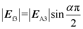
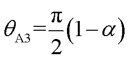
图2中,T代表发电机机端,故障点f位于以发电机故障相三次谐波相电势EA3为直径的圆上,θA3表示Ef3与EA3间的夹角。根据各电气量间满足的几何关系,求出Ef3的幅值和相位分别为
 (4)
(4)
 (5)
(5)
基于式(4)和式(5),将Ef3用EA3表示,二者满足的相量关系为
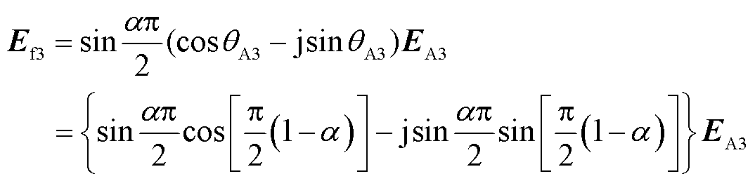 (6)
(6)
发电机定子绕组由单匝线圈串联组成,A相发生单相接地故障时,故障相定子绕组等效模型如图3所示。图中IA3为A相三次谐波对地电流,EA3为发电机A相三次谐波相电势;EAi3为A相第i匝线圈中点对中性点三次谐波电势,n为A相定子绕
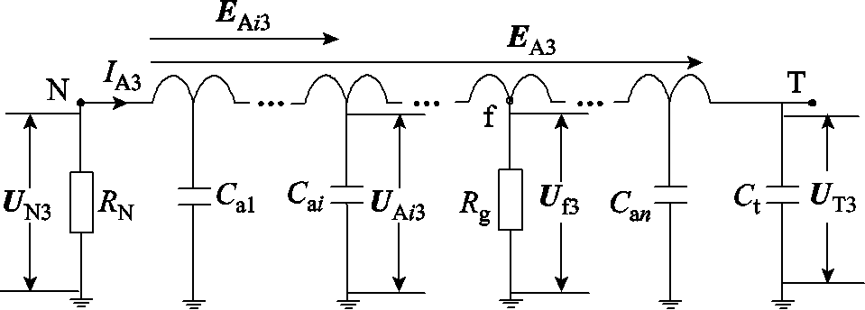
图3 发电机定子故障相绕组等效结构
Fig.3 Equivalent structure diagram of the generator stator’s fault phase winding
组总匝数,Cai为A相单匝线圈的等效对地电容值(i=1~n),UN3、UT3、Uf3、UAi3分别为发生接地故障后中性点、机端、故障点(f点)、第i匝线圈中点的三次谐波对地电压。
设UN3(0),UT3(0),Uf3(0)分别为发电机正常运行时中性点、机端、f点三次谐波电压。ΔUN3、ΔUT3、ΔUf3为故障前后中性点、机端、故障点三次谐波电压变化量,具体为
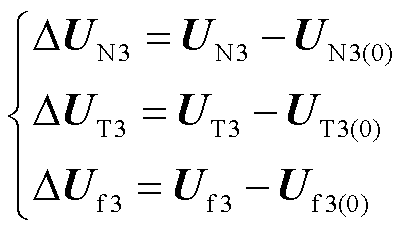 (7)
(7)
故障前后中性点与机端的三次谐波电压分别满足
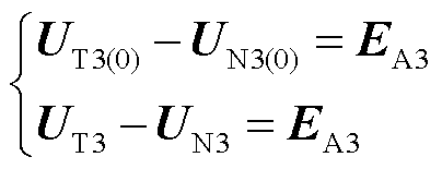 (8)
(8)
由于故障前后发电机的三次谐波电势不变,由式(7)和式(8)可得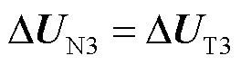 。由于故障前后发电机定子绕组上任意两点间的三次谐波电势均不变,因此故障前后各点三次谐波电压变化量相等,即
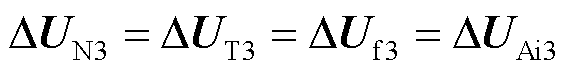 (9)
(9)
对于健全相绕组,上述关系仍然成立,定子绕组上各点三次谐波对地电压的变化量均为 。由于发电机正常运行时无故障电流,因此故障电流等于故障电流变化量,即
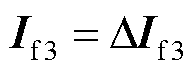 。针对接地故障点f,根据叠加原理,接地电流变化量等于定子绕组各点对地电容电流变化量与中性点接地电阻电流变化量之和。根据KCL,得到流过故障支路的三次谐波接地故障电流为
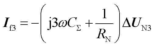 (10)
(10)
此外,根据图3,三次谐波接地故障电流也可表示为
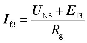 (11)
(11)
结合式(10)和式(11),得到
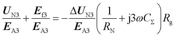 (12)
(12)
令UN3=(a+jb)EA3,=(c+jd)EA3,代入式(12)中,得到
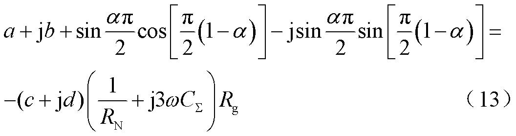
分离式(13)中的实部与虚部可得
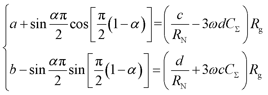 (14)
(14)
消去式(14)中的Rg,得到
 (15)
(15)
由于UN3和ΔUN3均可通过实测得到,利用傅里叶变换即可确定式(15)中的a、b、c、d。在求解式(15)并计算α的数值时,在[0,1]范围内选取使得该方程两侧相等的最优解。若出现重根情况,其中一个必为正确解,可与基波定位方法的计算结果取交集,确定最终的定位结果。
发电机在运行方式变化时,励磁调节将控制不同负荷工况下机端电压恒定。受励磁调节影响,三次谐波电势的幅值和相位将发生变化[23],如图4所示。
图4 励磁调节下三次谐波电势分布示意图
Fig.4 Third harmonic induced potential distribution under exciting regulation
文献[24]指出,不同负荷工况下,发电机定子绕组基波相电势分布形式与空载工况下绕组电势的分布形式相同。同理,当运行工况及励磁电流变化时,由于绕组结构不发生变化,各匝线圈三次谐波电势仍满足180°相带分布关系,各相量间的幅值相位关系并未发生变化。在不同工况下,式(5)均成立。此外,由于EA3、UN3和ΔUN3均可通过实测得到,式(14)在不同负荷工况下均成立,所提接地故障定位方法不受负荷变化和励磁调节的影响。
在工程应用中,该方法可与文献[19]提出的基波定位方法配合使用。当故障中性点基波零序电压幅值高于三次谐波电压幅值时,优先采用基波定位方法;反之,优先采用三次谐波定位方法。当定位计算结果存在多解时,可选取本文方法与基波定位方法计算结果中最接近的数值计算结果作为最终的定位结果。
为验证所提方法的有效性,基于PSCAD/ EMTDC软件,采用准分布参数模型构建发电机定子绕组等效模型并进行仿真验证。海洋核动力平台主发电机额定容量为31.25 MV·A,额定电压为10.5 kV,定子绕组电阻/相:1.528 mΩ,定子绕组电感/相:2.84 μH,定子绕组电容/相:0.397 μF,发电机外接系统对地电容/相:0.405 μF,中性点接地电阻:2 286 Ω。该汽轮发电机采用2分支绕组结构,极对数为1,总槽数为48,对应的槽距电角度为7.5°。
单一依赖基波零序电压进行的接地故障定位在发生高过渡电阻接地故障或故障点位于近中性点侧时可能出现定位多解情况。在A相第一分支绕组α=0.25处设置5 kΩ的单相接地故障,分别利用以文献[19]提出的基波定位方法以及本文提出的三次谐波定位方法,接地故障定位结果如图5所示。
图5 高阻接地故障定位结果
Fig.5 Ground fault location results under high ground fault resistance
分析图5a仿真结果可知,此时定位结果在0.252和0.334之间反复跳跃,若故障定位仅用于检修过程,上述两个定位结果均可作为备查故障位置,其中0.252为正确的定位计算结果。但若将定位结果用于有源接地故障消弧,此时无法确定应该输出的注入量。针对该故障条件,利用本文提出的三次谐波接地故障定位方法,接地故障定位结果为0.252,能够实现准确的故障定位。基波定位方法几种定位多解情况以及基于三次谐波方法的定位结果见表1,对应故障场景下,故障前后发电机中性点三次谐波电压幅值的仿真结果如图6所示。
表1 接地故障定位结果
Tab.1 Ground fault location results
故障场景UN1/V基波定位结果三次谐波定位结果 α=0.5, Rg=5 kΩ540.660.2850.5000.500 α=0.375, Rg=5 kΩ478.580.3350.3760.374 α=0.25, Rg=5 kΩ320.190.2520.3340.252 α=0.125, Rg=5 kΩ160.440.1250.3360.125
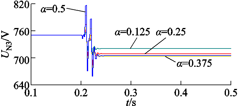
图6 故障前后发电机中性点三次谐波电压幅值(Rg=5 kΩ)
Fig.6 Third harmonic voltage amplitude of the generator neutral point before and after fault(Rg=5 kΩ)
图6中仿真计算曲线在故障后短时间内存在较大误差,这是因为保护算法中采用全周傅里叶算法计算相量时,在故障后一个周波内同时跨越了故障前和故障后两种状态,但该暂态过程持续时间短,不影响最终定位计算结果。针对接地过渡电阻较大情况,故障前后发电机中性点三次谐波电压幅值均较高,能够满足定位精度要求。表1仿真计算结果表明,存在某些接地过渡电阻较大且故障点靠近发电机中性点的故障场景下,仅利用基波零序电压实现接地定位时会出现多个定位结果。可将现有基波定位方法与本文提出的三次谐波定位方法相结合,在基波定位方法出现多解情况时,取二者定位结果中最相近的解作为最终的定位结果。
在数值计算过程中,需要确定a、b、c、d的计算精度。以Rg=5 kΩ且α=0.125情况为例,故障后中性点三次谐波电压为:696.9+j183.2 V,故障前后中性点三次谐波电压变化量为:-41.0+j47.0 V,故障相三次谐波相电势为:-975.5-j193.5 V。在计算a、b、c、d时,分别选取计算为0.01、0.001和0.000 1的情况,计算结果见表2。
分析表2计算结果可知,当a、b、c、d的计算精度为0.01时,将引起较大的定位误差;a、b、c、d的计算精度为0.001时,由于其计算精度造成的定位误差较小;a、b、c、d的计算精度为0.000 1时,定位误差几乎不受a、b、c、d的计算精度影响。本文在计算a、b、c、d时,计算精度取0.000 1。
表2 不同计算精度下的定位结果
Tab.2 Ground fault location results under different computational accuracy

计算精度abcd误差(%) 0.01-0.72-0.040.03-0.050.135 08 0.001-0.723-0.0440.031-0.0540.126 00.8 0.000 1-0.723 2-0.044 30.031 2-0.054 40.125 00
0.2 s时刻于A相第一分支绕组各线圈连接处设置接地过渡电阻为100 Ω的单相接地故障。测量机端和中性点电压,通过傅里叶变换确定EA3、UN3和ΔUN3。不同故障位置下故障前后发电机中性点三次谐波电压幅值如图7所示,基于三次谐波定位方法的接地故障定位结果如图8所示。
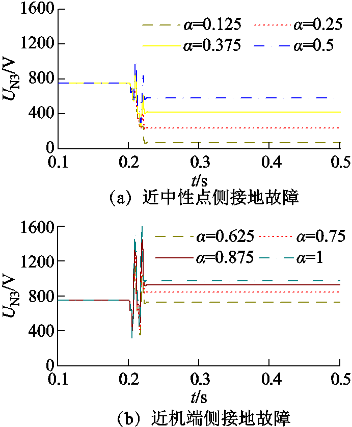
图7 故障前后发电机中性点三次谐波电压幅值(Rg=100 Ω)
Fig.7 Third harmonic voltage amplitude of the generator neutral point before and after fault (Rg=100 Ω)
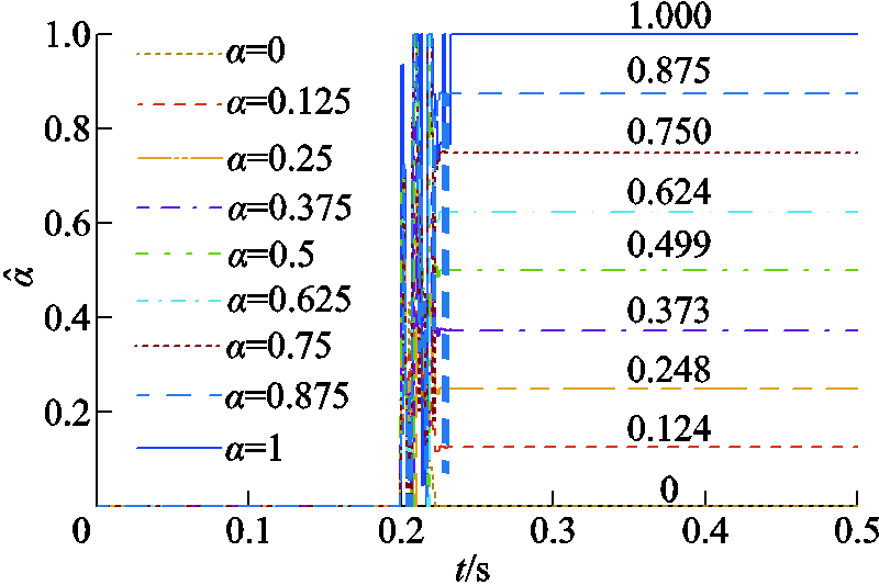
图8 不同位置下的接地故障定位仿真结果
Fig.8 Ground fault location results under different fault points
图7仿真结果表明,针对接地过渡电阻较小情况,故障前后发电机中性点三次谐波电压幅值均较高,最小幅值为α=0.125处,故障后中性点三次谐波电压为70.10 V,现有电压互感器测量精度能够实现准确测量。图8为不同故障位置下的定位计算结果,其中最大定位误差为0.8%。不同接地故障场景下的故障定位结果见表3。
表3 不同故障场景下的接地故障定位仿真结果
Tab.3 Simulation results of ground fault location under different fault conditions

故障场景中间计算结果定位结果 αRg/Ωabcd误差(%) 0500-0.426 8-0.303 20.327 3-0.312 800 1 000-0.607 2-0.229 40.147 1-0.239 100 2 000-0.697 6-0.132 80.056 7-0.142 700 0.125500-0.365 3-0.203 80.388 9-0.213 70.124-0.8 1 000-0.554 7-0.179 30.199 6-0.189 20.1250 2 000-0.664 6-0.110 80.089 7-0.120 70.1250 0.250500-0.346 5-0.088 30.407 9-0.098 40.249-0.4 1 000-0.525 4-0.113 00.229 0-0.123 00.249-0.4 2 000-0.642 6-0.077 80.111 9-0.087 80.250 0.375500-0.373 20.025 70.381 40.015 60.374-0.27 1 000-0.523 6-0.040 4 0.231 0-0.050 50.37-0.27 2 000-0.634 8-0.038 80.119 7-0.048 90.3750 0.500500-0.441 70.120 90.313 20.110 9 0.499-0.2 1 000-0.549 70.027 40.205 00.017 30.499-0.2 2 000-0.642 50.000 20.112 0-0.009 90.50 0.625500-0.541 50.182 60.213 50.172 80.624-0.16 1 000-0.599 80.080 00.155 00.070 00.6250 2 000-0.664 60.033 20.090 00.023 20.6250 0.750500-0.657 30.201 50.097 60.191 80.750 1 000-0.666 20.109 50.088 50.099 60.750 2 000-0.697 60.055 30.057 00.045 40.750 0.875500-0.771 30.174 5-0.016 80.165 00.8750 1 000-0.738 70.111 20.015 80.101 50.8750 2 000-0.736 50.063 10.018 00.053 20.8750 机端500-0.866 20.106 0-0.112 10.096 410 1 000-0.806 40.085 1-0.052 00.075 410 2 000-0.775 40.055 3-0.021 00.045 510
分析表2仿真结果可知,在不同发电机定子绕组接地故障场景下,所提基于三次谐波定位方法的定位误差在±1%以内,具有较高的定位精度,且不受故障位置和接地过渡电阻影响。
现有发电机定子接地故障仿真模型通常采用准分布参数模型,无法模拟不同负荷工况下发电机的励磁调节过程。发电机三次谐波电势受励磁调节影响,本文利用动模试验验证所提故障定位方法在不同负荷条件下的准确性。所用动模发电机容量为15 kV·A,额定电压为400 V,额定功率因数为0.8,发电机每相2个分支,极对数为1,总槽数为48。发电机通过升压变压器连接到实验室模拟的无穷大电力系统,实验系统如图9所示。
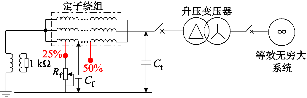
图9 动模实验系统主接线图
Fig.9 Electrical connection diagram of the dynamic experimental system
发电机A相分支绕组上存在几个引出的抽头,可通过滑线电阻器与发电机外壳连接,用于模拟α=0.25和0.50处的单相接地故障。发电机定子绕组对地电容为0.626 μF/相,机端外加对地电容为0.5 μF/相。发电机中性点通过接地变经高阻接地,接地变压器电压比为210 V:100 V,接地电阻阻值为1 kΩ,折算至一次侧为4 410 Ω。由于接地变阻抗较小,分析计算时可忽略其影响。动模试验系统照片如图10所示。

图10 动模试验系统图
Fig.10 A picture of the dynamic experiment system
控制发电机功率因数为额定功率因数不变,分别在25%负载、50%负载和100%负载条件下进行试验。0.3 s时在α=0.25处设置接地过渡电阻为100 Ω的单相接地故障,故障前后,故障相电势和中性点电压波形如图11所示。
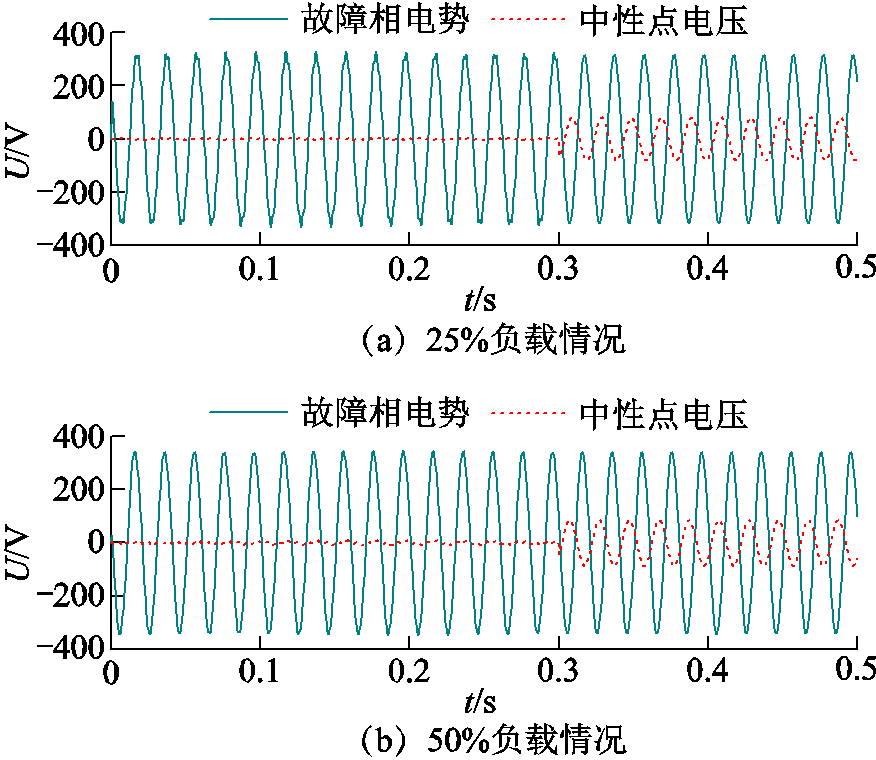
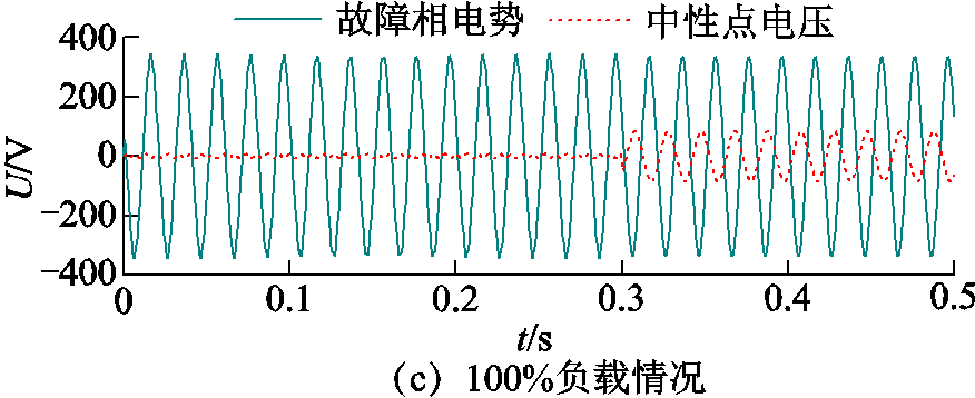
图11 电压波形试验结果
Fig.11 Voltage test results
对图11试验结果进行傅里叶变换,得到25%负载条件下:EA3=2.91V∠-146.27°,UN3(0)=2.23V∠27.73°,UN3=0.71V∠-24.19°;50%负载条件下:EA3= 4.77V∠-73.58°,UN3(0)=3.65V∠100.49°,UN3= 1.17V∠49.09°:100%负载条件下:EA3=7.28V∠-168.77°,UN3(0)=5.57V∠5.26°,UN3=1.78V∠ -46.69°。
在负载增大时,受负荷去磁作用影响,发电机相电势将减小,机端电压跌落。为维持机端电压恒定,励磁电流增大,此时受励磁调节和负荷去磁作用的双重影响,基波电势维持不变。而由于主变压器三角绕组的隔离作用,负荷的去磁作用对三次谐波电势无影响,因此在负荷增大时,受励磁调节影响,三次谐波电势增加,且相位发生偏移。在以上三种负荷工况下,基于本文提出的三次谐波电势定位方法的定位计算结果如图12所示。
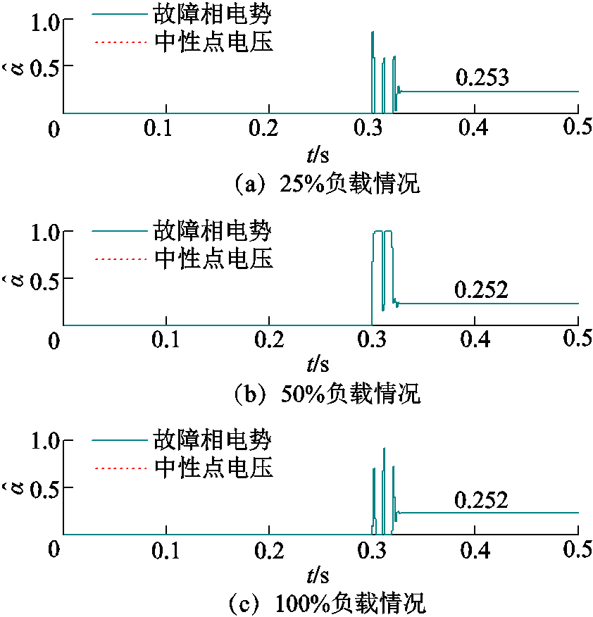
图12 接地故障定位计算结果
Fig.12 Ground fault location calculation results
以25%负载情况为例,此时相较于准确的故障位置而言,定位误差为1.2%。相较于仿真结果而言,试验结果定位误差增大,这主要是由于动模试验机组电压等级低,三次谐波电压小,互感器测量误差较大导致定位精度降低,但仍然能够准确定位至故障线圈。在接地过渡电阻为100 Ω情况下,对应不同运行工况及不同故障位置下的定位计算结果见表4。
表4 接地故障定位试验计算结果
Tab.4 Test results of ground fault location

故障场景中间计算结果定位结果 负载(%)αabcd误差(%) 250.25-0.223 60.032 8-0.002 20.000 60.2531.2 0.50-0.406 90.287 0-0.001 0-0.000 40.497-0.6 500.25-0.225 80.032 2-0.002 20.000 60.2520.8 0.50-0.410 60.284 8-0.001 0-0.000 40.498-0.4 1000.25-0.223 60.032 8-0.002 20.000 60.2520.8 0.50-0.406 90.287 0-0.001 0-0.000 40.497-0.6
表4试验结果表明,不同负载工况下,所提定位方法仍然能够实现接地故障定位,因此所提方法不受运行工况和励磁调节影响。
本文提出一种基于三次谐波电势分布特征的发电机接地故障定位方法,得出如下结论:
1)现有基于基波零序电压的发电机接地故障定位方法存在多解问题,无法为有源消弧技术提供可靠的定位保证。
2)基于定子绕组三次谐波相电势180°相带分布特点,本文建立包含三次谐波故障电势、中性点三次谐波电压、中性点三次谐波电压变化量的解析定位方程。方程中不含接地过渡电阻,适用于未安装注入式保护设备的海洋核动力平台发电机。
3)仿真和动模试验结果表明,所提定位方法具有较高的准确性,且不受故障位置、接地过渡电阻和运行工况影响。该方法可与基波定位方法协同配合,消除基波定位方法在中性点附近的定位死区,并解决基波定位方法的多解问题。
4)所提定位方法对于定子绕组满足60°相带分布特点,且中性点采用经高阻接地的发电机而言均适用。
参考文献
[1] 尹项根, 王义凯, 李鹏, 等. 海洋核动力平台电网安全问题及保护技术研究[J]. 电力系统保护与控制, 2020, 48(22): 9-17. Yin Xianggen, Wang Yikai, Li Peng, et al. Study on security problems and protection technologies of the floating nuclear power plant grid[J]. Power System Protection and Control, 2020, 48(22): 9-17.
[2] 方晓伦, 杨强, 刘国锋, 等. 海上多平台互联电力系统故障后的供电恢复策略[J]. 电力系统自动化, 2021, 45(7): 53-61. Fang Xiaolun, Yang Qiang, Liu Guofeng, et al. Power supply restoration strategy for offshore multi-platform interconnected power system with faults[J]. Automation of Electric Power Systems, 2021, 45(7): 53-61.
[3] Wang Yikai, Yin Xianggen, Qiao Jian, et al. Generator stator windings ground fault diagnosis for generator-grid directly connected system of floating nuclear power plant[J]. Energy Reports, 2021, 7: 460-469.
[4] 高俊国, 孟睿潇, 胡海涛, 等. 电机定子绝缘老化寿命预测研究进展[J]. 电工技术学报, 2020, 35(14): 3065-3074. Gao Junguo, Meng Ruixiao, Hu Haitao, et al. Research progress on prediction of aging life of motor stator insulation[J]. Transactions of China Electrotechnical Society, 2020, 35(14): 3065-3074.
[5] 郝亮亮, 李佳慧, 段贤稳, 等. 核电多相环形无刷励磁机转子绕组短路故障特征分析[J]. 电工技术学报, 2020, 35(6): 1251-1261. Hao Liangliang, Li Jiahui, Duan Xianwen, et al. Characteristic analysis of short-circuit fault in rotor winding of nuclear power multi-phase annular brushless exciter[J]. Transactions of China Electrotechnical Society, 2020, 35(6): 1251-1261.
[6] 田代宗, 孙宇光, 王善铭, 等. 多相整流永磁同步发电机绕组内部相间短路的故障分析[J]. 电工技术学报, 2020, 35(6): 1262-1271. Tian Daizong, Sun Yuguang, Wang Shanming, et al. Analysis of stator internal phase-to-phase short-circuit in the multiphase permanent magnet synchronous generator with rectifier load system[J]. Transactions of China Electrotechnical Society, 2020, 35(6): 1262-1271.
[7] 赵洪森, 戈宝军, 陶大军, 等. 大型核电汽轮发电机定子内部短路故障时局部电磁力分布研究[J]. 电工技术学报, 2018, 33(7): 1497-1507. Zhao Hongsen, Ge Baojun, Tao Dajun, et al. Local electromagnetic force distribution study on giant nuclear turbo-generators with stator short-circuit fault[J]. Transactions of China Electrotechnical Society, 2018, 33(7): 1497-1507.
[8] 何玉灵, 张文, 张钰阳, 等. 发电机定子匝间短路对绕组电磁力的影响[J]. 电工技术学报, 2020, 35(13): 2879-2888. He Yuling, Zhang Wen, Zhang Yuyang, et al. Effect of stator inter-turn short circuit on winding electromagnetic forces in generators[J]. Transactions of China Electrotechnical Society, 2020, 35(13): 2879-2888.
[9] Wang Yikai, Yin Xianggen, Xu Wen, et al. Active arc suppression algorithm for generator stator winding ground fault in the floating nuclear power plant[J]. IEEE Transactions on Power Delivery, PP(99): 1.
[10] 蒋顺平, 丁勇, 石祥建, 等. 位移过电压抑制转接地故障消弧的柔性电源控制方法[J]. 电力系统自动化, 2021, 45(20): 140-147. Jiang Shunping, Ding Yong, Shi Xiangjian, et al. Control method of displacement overvoltage suppression switching to ground fault arc-suppression for flexible power source[J]. Automation of Electric Power Systems, 2021, 45(20): 140-147.
[11] 康逸群, 宋梦琼. 大型发电机注入式定子接地保护应用与分析[J]. 电气技术, 2020, 21(1): 129-132. Kang Yiqun, Song Mengqiong. Application and analysis of voltage-injection stator ground protection for large-sized generator[J]. Electrical Engineering, 2020, 21(1): 129-132.
[12] 毕大强, 王祥珩, 李德佳, 等. 发电机定子绕组单相接地故障的定位方法[J]. 电力系统自动化, 2004, 28(22): 55-57, 94. Bi Daqiang, Wang Xiangheng, Li Dejia, et al. Location detection for the stator single-phase ground fault of a generator[J]. Automation of Electric Power Systems, 2004, 28(22): 55-57, 94.
[13] 陈俊, 刘梓洪, 王明溪, 等. 不依赖注入式原理的定子单相接地故障定位方法[J]. 电力系统自动化, 2013, 37(4): 104-107. Chen Jun, Liu Zihong, Wang Mingxi, et al. Location method for stator single-phase ground fault independent of injection type principle[J]. Automation of Electric Power Systems, 2013, 37(4): 104-107.
[14] 贾文超, 黄少锋. 水轮发电机定子单相接地故障定位新方法[J]. 电力自动化设备, 2017, 37(2): 134-139. Jia Wenchao, Huang Shaofeng. Stator single-phase grounding fault location for hydro-generator[J]. Electric Power Automation Equipment, 2017, 37(2): 134-139.
[15] 尹项根, 王义凯, 谭力铭, 等. 故障机理深度关联的大型发电机保护新原理探讨[J]. 电力系统保护与控制, 2021, 49(22): 1-7. Yin Xianggen, Wang Yikai, Tan Liming, et al. Discussion on a new principle of large generator protection deeply associated with fault mechanisms[J]. Power System Protection and Control, 2021, 49(22): 1-7.
[16] 王育学, 尹项根, 张哲, 等. 基于接地电流的大型发电机定子接地保护及精确定位方法[J]. 中国电机工程学报, 2013, 33(31): 147-154, 18. Wang Yuxue, Yin Xianggen, Zhang Zhe, et al. A novel protection and precise location method based on grounding currents for stator ground faults of large generators[J]. Proceedings of the CSEE, 2013, 33(31): 147-154, 18.
[17] 黄少锋, 贾文超. 大型汽轮发电机定子单相接地故障定位新方法[J]. 电力系统保护与控制, 2017, 45(9): 35-40. Huang Shaofeng, Jia Wenchao. A new fault location method for stator single-phase ground fault in large turbine generator[J]. Power System Protection and Control, 2017, 45(9): 35-40.
[18] 殷林鹏, 桂林, 张琦雪, 等. 基于基波电势分布特征的大型发电机定子接地故障定位方法[J]. 电力自动化设备, 2019, 39(7): 141-146. Yin Linpeng, Gui Lin, Zhang Qixue, et al. Stator grounding fault location method based on distribution characteristics of fundamental wave potential[J]. Electric Power Automation Equipment, 2019, 39(7): 141-146.
[19] 王义凯, 尹项根, 乔健, 等. 海洋核动力平台发电机定子绕组单相接地故障风险分析与实时定位[J]. 电力自动化设备, 2022, 42(4): 178-183. Wang Yikai, Yin Xianggen, Qiao Jian, et al. Risk analysis and real-time locating of single-phase grounding fault of generator stator winding for offshore nuclear power plant[J]. Electric Power Automation Equipment, 2022, 42(4): 178-183.
[20] 王维俭. 电气主设备继电保护原理与应用[M]. 2版. 北京: 中国电力出版社, 2002.
[21] 党晓强, 邰能灵, 刘俊勇, 等. 绝缘状况原理在大型水轮发电机3次谐波量接地保护中的应用[J]. 中国电机工程学报, 2012, 32(34): 129-134, 19. Dang Xiaoqiang, Tai Nengling, Liu Junyong, et al. Application of ground insulation state to improve ground fault protection using third harmonic voltage for huge hydraulic generator[J]. Proceedings of the CSEE, 2012, 32(34): 129-134, 19.
[22] 桑建斌, 包明磊, 李玉平, 等. 大型汽轮发电机3次谐波电压定子接地保护方案的研究与改进[J]. 电力自动化设备, 2017, 37(10): 177-183. Sang Jianbin, Bao Minglei, Li Yuping, et al. Research and improvement of stator grounding protection based on third-harmonic voltage for large-scale turbine generator[J]. Electric Power Automation Equipment, 2017, 37(10): 177-183.
[23] Fulczyk M, Mydlikowski R. Influence of generator load conditions on third-harmonic voltages in generator stator winding[J]. IEEE Transactions on Energy Conversion, 2005, 20(1): 158-165.
[24] 谭力铭, 尹项根, 王义凯, 等. 自适应工况的大型水轮发电机定子接地故障定位方法[J]. 电工技术学报, 2022, 37(17): 4411-4422. Tan Liming, Yin Xianggen, Wang Yikai, et al. An adaptive load-based location method of stator ground fault for large hydro-generators[J]. Transactions of China Electrotechnical Society, 2022, 37(17): 4411-4422.
Abstract Floating nuclear power plant operates in a wet and salty environment. The main equipment in the power system is easy to be corroded, and generator stator winding ground faults occur frequently. To avoid the power loss of the nuclear reactor loads caused by the generator's blind and rapid tripping, the active arc suppression technology is adopted to realize stator ground fault arc suppression and achieve smooth load transfer. The difference between the active arc suppression technology of the generator and the distribution network lies that: the applied voltage in the neutral point is different for ground faults at different fault points on the stator windings. Therefore, reliable fault point location should be realized.
For the problem of generator stator ground fault location, the influence of the winding structure and operating condition should be considered. The existing ground fault location methods usually utilize the fundamental zero-sequence voltage. They can obtain accurate location results in most fault scenarios. However, in some fault scenarios, when the fault transition resistance is large or the fault point is close to the neutral point, multiple solutions are easy to be located. And it cannot provide reliable location guarantee for active arc suppression technology. Aiming at the problems of the existing fundamental potential based location methods, a new location algorithm based on the third harmonic potential distribution characteristics is proposed. Based on the 180° phase-band distribution of the third harmonic potential of each coil, the geometric relation between the third harmonic fault potential and the third harmonic phase potential is constructed. Taking the third harmonic fault current as the intermediate quantity, the analytical location equation containing the third harmonic fault potential, neutral grounding voltage and neutral grounding voltage variation is established. Grounding transition resistance is not included in the equation, which is suitable for the generator in the floating nuclear power plant without injection protection equipment.
Simulation results show that under different generator stator windings ground fault scenarios, the location error is within ±1%, which has a high accuracy under different fault points and fault transition resistances. Dynamic test results show that the proposed method can realize accurate ground fault location under different load conditions, and it is not affected by operating conditions and excitation regulation. In engineering application, the existing fundamental voltage based method can be combined with the proposed third harmonic based method proposed in this paper. When the fundamental voltage based method has multiple location solutions, the closest solution of the two location methods is taken as the final localization result.
The following conclusions can be drawn from the simulation analysis: (1) The existing ground fault location methods based on fundamental zero-sequence voltage have some problems and cannot provide reliable location guarantee for active arc suppression technology. (2) Based on the distribution characteristics of the 180° phase-band of the third harmonic potential of the stator windings, the analytical locating equation including the third harmonic fault potential, the third harmonic neutral point voltage and the third harmonic neutral point voltage variation is established in this paper. It does not include the fault transition resistance and is applicable to floating nuclear power plant generators without injection protection equipment. (3) Simulation and dynamic model test results show that the proposed method has high accuracy and is not affected by fault location, fault transition resistance and operating conditions. This method can cooperate with the fundamental location method to eliminate the location dead zone and solve the multi-solution problem of the fundamental voltage based location method. (4) The proposed method is applicable to generators whose stator windings meet the characteristics of 60° phase-band distribution and whose neutral point is grounded by high resistance.
keywords:Floating nuclear power plant, generator stator winding, ground fault location, third harmonic, phase-band distribution characteristic
国家自然科学基金(51877089)和国家重点研发计划(2017YFC0307800)资助项目。
收稿日期 2022-05-04
改稿日期 2022-06-29
DOI:10.19595/j.cnki.1000-6753.tces.220727
中图分类号:TM311
王义凯 男,1996年生,博士研究生,研究方向为电力系统继电保护。E-mail:742657004@qq.com
谭力铭 男,1998年生,硕士研究生,研究方向为电力系统继电保护。E-mail:904632172@qq.com(通信作者)
(编辑 赫蕾)