 和
和 分别为输入电压和输出电压,
 和
和 分别为一次、二次侧H桥交流电压,
 为变压器漏感,
 为高频电感电流;图1b为DAB的稳态运行波形,
 为一次侧H桥的内移相比,
 为二次侧H桥的内移相比,
 为一次、二次侧H桥电压
 和
和 之间的移相比。
摘要 电压模式下双有源桥变换器在输入电压改变或负载突变时,会在变压器一次侧产生暂态直流偏置电流,从而导致电感电流峰值过大、变压器磁心饱和等问题。该文提出一种改进的三移相(ITPS)控制策略,用以消除双有源桥(DAB)暂态直流偏置电流。ITPS控制策略首先通过电感电流有效值优化策略确定稳态过程移相比,建立DAB直接功率控制模型。当DAB运行模式改变时,通过在过渡过程中增加一个暂态周期,调节开关管在暂态周期中的占空比,以维持变压器的伏秒平衡,抑制暂态偏置电流,使系统在一个周期内可以快速达到稳态。该策略将DAB的稳态性能与动态性能的优化相结合,在保证对电流有效值优化的同时,能实现快速的暂态响应。仿真及实验结果表明,ITPS策略在不同稳态和暂态工况下都具有优越性能,具有一定的工程应用价值。
关键词:暂态直流偏置 双有源桥变换器 改进三移相调制 有效值电流
双有源桥(Dual Active Bridge, DAB)变换器具有能量双向流动、开关器件电压电流应力较小、输入输出电气隔离、高功率密度以及软开关等特 点[1-2]。目前,广泛应用于电动汽车、直流配电网、微电网、分布式能源等领域[3-5]。
DAB最常用的调制方式是单移相(Single Phase Shift, SPS)调制[6]。SPS通过调整变压器一次、二次侧输出方波之间的移相角控制DAB功率传输的大小和方向[7],控制方式简单,但在输入输出电压不匹配及轻载运行时会产生较大的回流功率,导致DAB有效值(Root Mean Square, RMS)电流过大,增加系统损耗[8]。为了提高变换器效率,双重移相(Dual Phase Shift, DPS)调制、三重移相(Triple Phase Shift, TPS)调制等方式相继被提出,相比于SPS调制,DPS调制、TPS调制功率调节范围增大、灵活性增强,能够在给定传输功率下,对电流应力或有效值电流进行优化[9-10]。文献[11]提出一种扩展移相控制下的回流功率和电流应力优化方法,轻载情况下DAB效率有较大提升。文献[12]通过建立全局最优条件模型对DAB进行优化,根据传输功率与RMS电流间的关系将DAB划分六种工作模态,并对各工作模态进行分析,实现全局有效值电流最小。以上对DAB转换器的分析是基于时域分析,计算较为复杂。为了简化分析,文献[13]从频域出发,利用傅里叶分解建立DAB频域模型,提出一种基波占空比调制(Fundamental Duty Modulation, FDM)策略,通过对SPS调制策略下的RMS电流的基频分量进行优化,有效地减少了无功电流,然而当输入电压较低、功率较小时,谐波分量就会成为主导。文献[14]充分考虑基波和多次谐波分量,提出一种多次无功电流抑制(Multi-frequency Reactive-current Suppression, MRS)策略,对DAB的RMS电流进行优化,但未给出控制器实现方式,也没有对此策略下DAB模态进行详细分析。
传统的DAB控制大多采用电压单环控制,动态响应仅由反馈电压误差确定,无法直接调节电感电流的动态特性,输出电压动态响应较差[15]。为了改善DAB的动态响应,文献[16-17]提出了虚拟功率直接控制,保证DAB变换器能在启动阶段、负载或输入电压扰动时,输出电压具有快速动态响应。但是这些控制的提出都是基于一个开关周期内的平均模型,在分析过程中忽略开关周期内的暂态过程。在快速瞬态响应期间,变压器一次、二次电压可能存在伏秒不平衡,产生暂态直流偏置电流。暂态直流偏置电流会导致变压器铁心单向深度饱和,磁化电流剧增,损耗增加,严重时会在主回路产生过大的峰值电流,对开关管造成损害,降低变换器的可靠性[18]。
大多数暂态直流偏置抑制策略通过在暂态过程的第一个开关周期内控制“伏秒”至新的平衡状态,以消除电路中的电流尖峰,使电感电流在一个开关周期后即进入稳态[19]。文献[20]推导了双移相控制下功率与移相比关系,通过对暂态后半个周期进行移相比调整,对暂态直流偏置电流进行抑制,避免了瞬时电流尖峰,但缺乏闭环暂态响应的分析验证。文献[21]提出一种基于三移相调制的暂态直流偏置抑制策略,通过在暂态过程增加一个与电压增益及3个移相角有关的移相比,调整电感的峰值电流,以抑制暂态直流偏置电流。但其只分析了DAB变换器输入输出为固定电压源的情况,未对输出为无源阻性负载的情况进行分析。另外,其未考虑暂态抑制过程中移相比饱和的情况。
为提高DAB运行效率,降低直流偏置电流对DAB动态性能的影响,确保功率器件及高频变压器的可靠运行,本文提出了基于直接功率控制的双有源桥暂态直流偏置抑制策略,可在一个开关周期内对电感电流的直流偏置分量进行抑制。本文首先回顾了基于多次谐波最小化的RMS策略,推导并分析了DAB在此策略下的直接功率控制模型。然后,对不同输出功率阶跃模式下的暂态直流偏置电流进行分析,给出了抑制暂态直流偏置电流的移相比组合方案及控制器实施方法。最后,基于Matlab/ Simulink软件对理论分析结果进行仿真证明,并搭建实验样机对所提策略下暂态性能和稳态性能进行验证,结果表明该策略在运行状态改变时,能有效抑制暂态过程电流尖峰,提高DAB闭环暂态响应,同时实现RMS电流优化,具有一定的工程应用价值。
图1a为DAB的拓扑结构,图中, 和
和 分别为输入电压和输出电压,
 和
和 分别为一次、二次侧H桥交流电压,
 为变压器漏感,
 为高频电感电流;图1b为DAB的稳态运行波形,
 为一次侧H桥的内移相比,
 为二次侧H桥的内移相比,
 为一次、二次侧H桥电压
 和
和 之间的移相比。
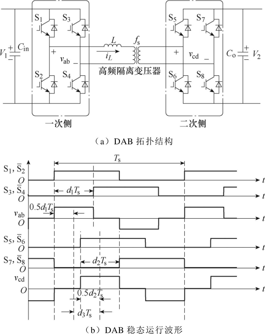
图1 DAB拓扑及波形
Fig.1 DAB topology and waveforms
文献[14]考虑基波和多次谐波分量对RMS电流优化,提出MRS策略,其一次侧及二次侧移相比关系为
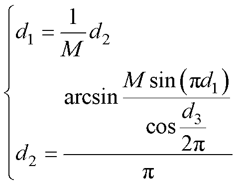 (1)
(1)
式中, 。
。
本文基于MRS策略展开分析,由式(1)得
 (2)
(2)
对于式(2)很难得到其显性解,在此利用牛顿迭代法近似确定 、
、 与
与 关系式为
关系式为
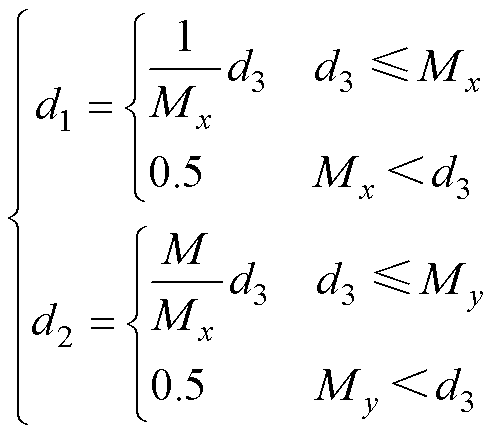 (3)
(3)
其中
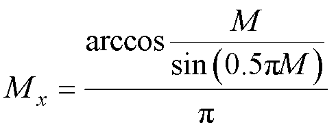
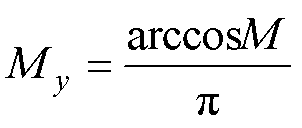
由式(3)可知, 、
、 均可由
均可由 表示,则可通过
 确定DAB不同工作模式。根据方波电压零电平区域是否有重叠,可将其分为两种运行模式,其物理意义可通过式(4)表示。
 时,电压零电平区域有重叠;
 时,电压零电平区域无重叠。
 (4)
(4)
图2给出了 、
、 、
、 与
与 的关系曲线。由图2可知,
 时,移相比
时,移相比 、
、 均未饱和;
均未饱和; 时,需对
时,需对 、
、 是否饱和进行进一步讨论,DAB工作模式及划分依据定义见表1。
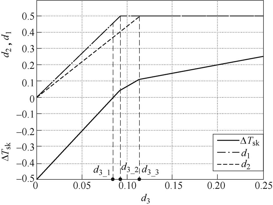
图2  、
、 、
、 与
与 的关系曲线
的关系曲线
Fig.2 The relationship curves of  、
、 、
、 and
and 
表1 DAB工作模式
Tab.1 The working mode of DAB
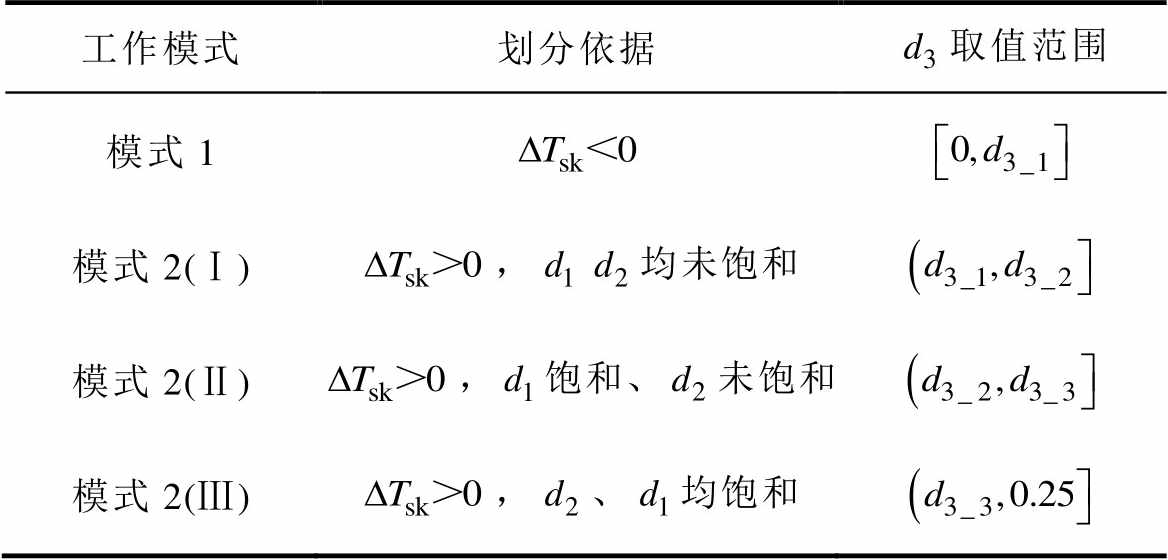
工作模式划分依据取值范围 模式1 模式2(Ⅰ),均未饱和 模式2(Ⅱ),饱和、未饱和 模式2(Ⅲ),、均饱和
定义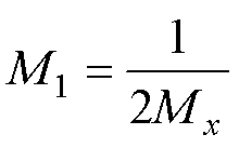 ,
,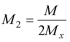 ,
, 、
、 、
、 分别表示为
分别表示为
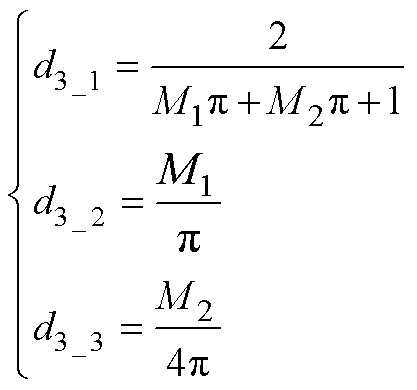 (5)
(5)
图3给出了DAB不同工作模式的电压和电感电流波形。假设 稳态周期内半波对称,根据伏秒平衡,可求得各个模式下电感电流初值为
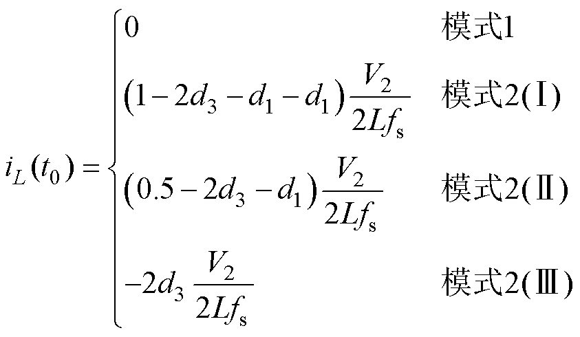 (6)
(6)
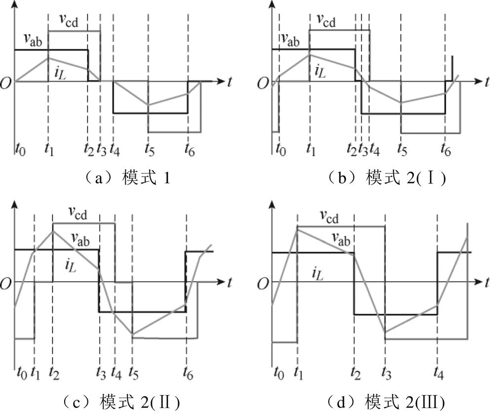
图3 不同模式下DAB的电压和电流波形
Fig.3 Voltage and current waveforms of DAB in different modes
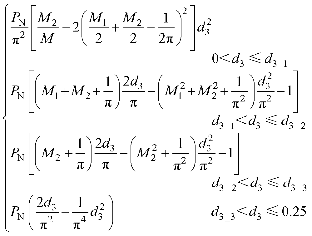
结合式(3)、式(5)和式(6),移相比和传输功率的关系可表示为

 (7)
(7)
其中
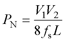
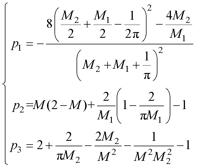
由式(7)可知,移相比决定输出功率的范围,同理可通过输出功率调节移相比的变化。首先,通过移相比区间边界值 、
、 、
、 确定输出功率区间边界值
 、
、 、
、 ,即
,即
 (8)
(8)
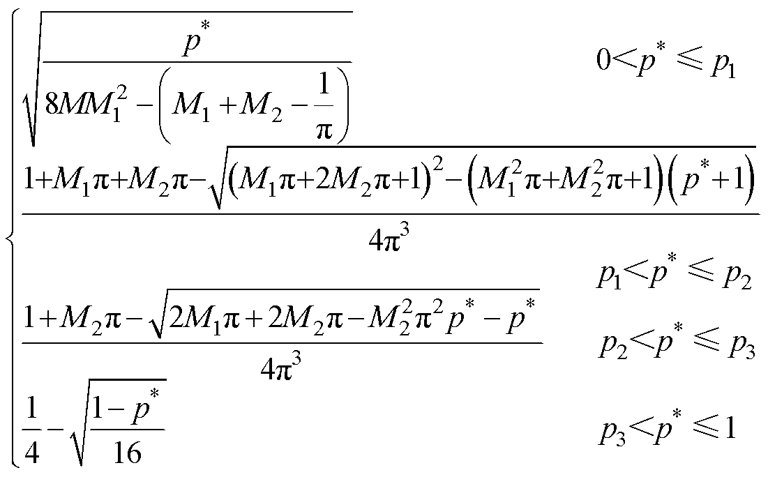
定义输出功率标幺值为 ,则可得DAB直接功率控制(Direct Power Control, DPC)模型为

 (9)
(9)
传统的DAB控制方式下各功率开关管的占空比恒为50%,通过改变移相比实现一次、二次侧能量传递,由式(9)知,DAB在功率动态调节的过程中,移相角会发生突变,原稳态运行状态发生改变,此时电感电流波形不再对称,初始稳态结束时刻(暂态开始时刻)的电流值与最终稳态开始时刻的电流值(暂态结束时刻)存在差值,且差值越大,暂态直流偏置量越大。由式(6)可知,DAB在模式1范围内阶跃时初始稳态结束时刻的电流值与最终稳态开始时刻的电流值均为零,变压器电压在一个周期的伏秒积为零,不会导致暂态直流偏置,直接过渡到稳态,在此不需要对模式1范围内的功率阶跃进行分析。另外,模式2(Ⅱ)和模式2(Ⅲ)可看作模式2(Ⅰ)移相比饱和的特殊形式,其暂态阶跃情况类似,暂态分析过程中对模式2不做细分。DAB在模式2范围内及模式1、模式2范围阶跃时,初始稳态结束时刻的电流值与最终稳态开始时刻的电流值不相等,会产生暂态直流偏置。
从运行模式分析出发,将DAB功率变化分为三种工况:工况①定义为传输功率在重载范围即模式2范围内的阶跃;工况②定义为功率由轻载变为重载即从模式1阶跃至模式2;工况③定义为功率由重载变为轻载,即从模式2阶跃至模式1。图4给出三种典型工况下未进行暂态优化时的偏置电流曲线,图中,A1为初始稳态的起点,B1初始稳态的中点,C1为初始稳态的结束点, 为暂态时刻的中点,A2为最终稳态的起点,B2最终稳态的中点,C2为最终稳态的结束点。对于模式2范围内的阶跃及模式1与模式2范围内的阶跃,当功率增大时,最终稳态的电流应力均大于初始稳态的电流应力。然而,电感电流不能突变,这会导致伏秒不平衡,电感电流的平均值大于零,出现正的直流偏置。同理,当功率减小时,最终稳态的电流应力均小于初始稳态的电流应力,出现负的直流偏置。另外,由于移相角的突变,开关器件触发脉冲的占空比会出现暂时不对称,这也是图4b中H桥二次电压产生窄脉冲的原因。
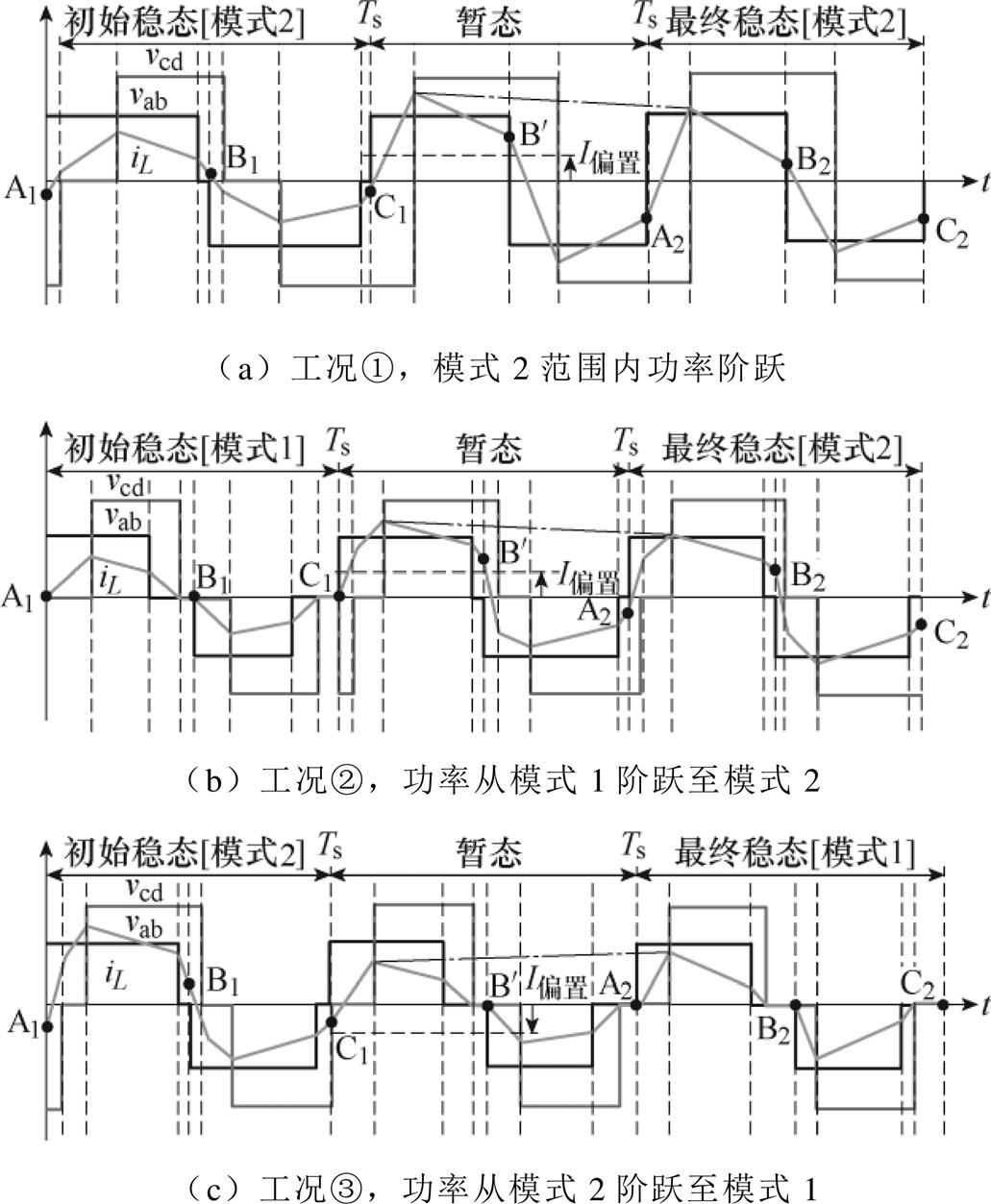
图4 暂态直流偏置工况
Fig.4 Transient DC bias case
直流偏置数学模型是进行直流偏置抑制控制的基础。直流偏置模型的建立需要己知暂态过程电流各个节点的表达式,而各电流节点的表达式由稳态过程的移相比控制策略决定,因此,本文在最小RMS策略的基础上,提出了一种改进的三移相(Improved Triple Phase Shift, ITPS)暂态直流偏置抑制策略。通过增加一个暂态周期,此周期内每个开关的通断占空比不再为50%,通过调整移相比,改变开关管在暂态过程中的通断占空比,使系统在一个开关周期内可以快速达到稳态。
定义 、
、 、
、 为初始稳态工况下的移相比,
 、
、 、
、 为最终工况下的移相比,
 、
、 、
、 为暂态前半个周期移相比,
 、
、 、
、 为后半个周期移相比。
图5给出了ITPS抑制策略示意图,优化策略通过改变移相比调整暂态中间时刻电感电流值 ,使系统在一个周期内可以快速达到稳态。

图5 ITPS抑制策略示意图
Fig.5 Schematic diagram of ITPS suppression strategy
调整策略表示为
 (10)
(10)
在实际应用中,移相比 、
、 都被限制在[0, 0.5]的范围,
 限制在0.25的范围内。由于式(3)中已对
 、
、 进行限制,因此这里只需考虑移相比
 的取值即可。另外,不论移相比如何改变,需确保
 ,否则难以在一个周期内过渡到稳态,即
 需满足
需满足
 (11)
(11)
下面对各工况的暂态抑制策略进行详细分析。
1)工况①,传输功率在模态2范围内的阶跃
当 且
且
 时,DAB在模式2范围阶跃,图6给出了暂态直流偏置抑制策略示意图,在暂态周期内除
 、
、 外,其他开关管的通断占空比不再为50 %。通过改变移相比,调整开关管的导通时间,进而调整
 的位置,使系统在一个周期内可以快速达到稳态。
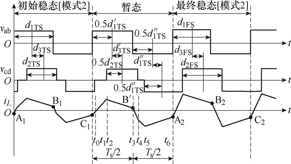
图6 工况①中暂态直流偏置抑制策略示意图
Fig.6 Schematic diagram of ITPS in Case ①
暂态过程中不同时刻电感电流值可表示为
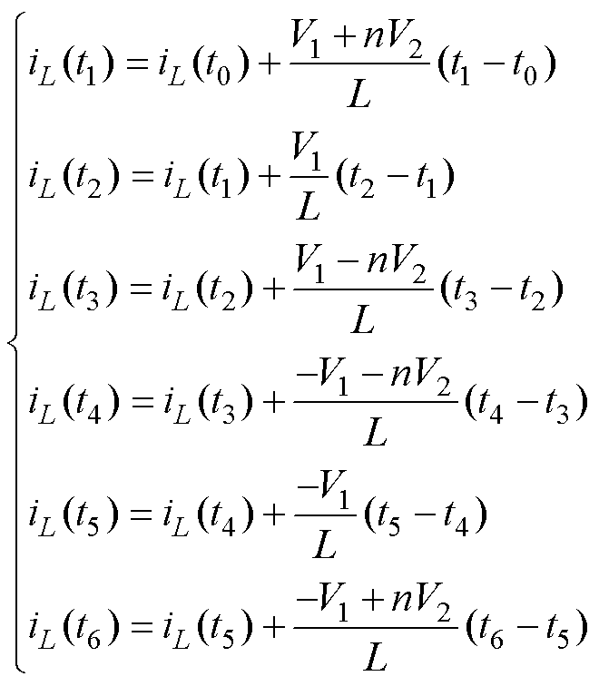 (12)
(12)
式中, ;
; 。则
。则 、
、 可表示为
可表示为
 (13)
(13)
 (14)
(14)
联立式(12)和式(13),可求得 时刻电流值为

 (15)
(15)
联立式(12)、式(15)可确定前半个暂态周期移相比的表达式为
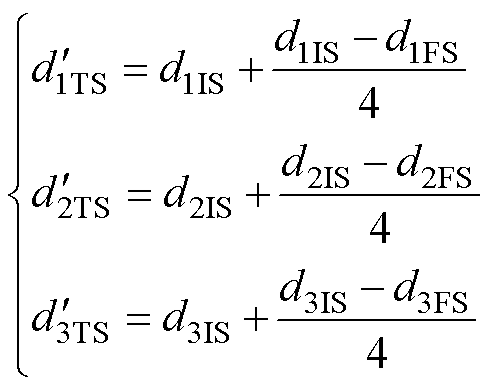 (16)
(16)
根据式(11)的分析,需对式(16)中 进行详细讨论,可将其细分为三种情况。
(1) ,此时需将
,此时需将 限制在0.25,即需前半周期移相比满足
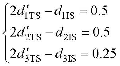 (17)
(17)
同时结合式(15),可得暂态过程周期移相比为
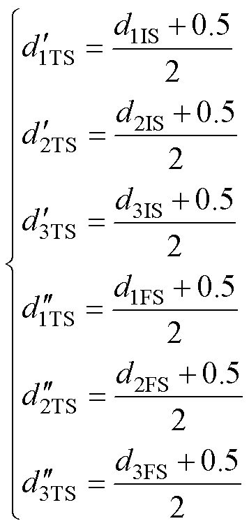 (18)
(18)
(2) 时,令
时,令
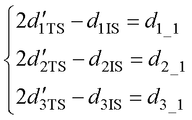 (19)
(19)
结合式(15)暂态过程移相比可表示为
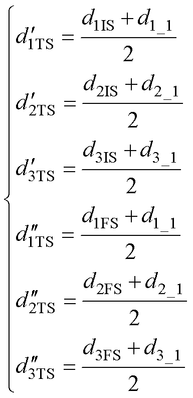 (20)
(20)
(3) ,此时
,此时
 (21)
(21)
同理,结合式(15)、式(21)可得暂态过程后半个周期移相比为
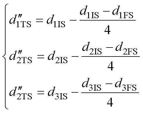 (22)
(22)
2)工况②,功率从模态1阶跃至模态2
当 且
且
 时,DAB在从模式1阶跃至模式2,由于
 ,
, ,为确保
,为确保 ,则需在前半个周期将其过渡至模式1与模式2的临界状态,此时
 ,令
,令
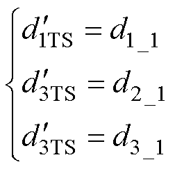 (23)
(23)
通过列写暂态过程中不同时刻电感电流值,再由 可确定暂态过程后半个周期移相比为
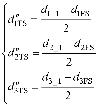 (24)
(24)
3)工况③,功率从模态2阶跃至模态1
当 且
且
 时,此时从模式2阶跃至模式1,由于稳态2起始时刻电流
 ,因此需在暂态后半个周期保证其过渡至模式1与模式2的临界状态,令
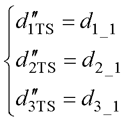 (25)
(25)
通过列写暂态过程中不同时刻电感电流值,再由 可确定暂态过程前半个周期移相比为
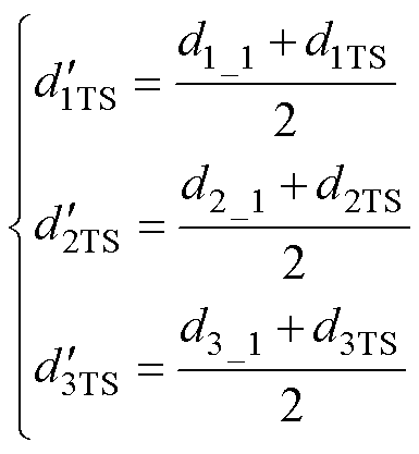 (26)
(26)
4)工况④,传输功率在模式1范围内的阶跃
当 且
且
 时,DAB在模式1的范围内阶跃,这种工况下,
 ,变压器电压在一个周期的伏秒积为零,不会导致暂态直流偏置,直接过渡到稳态。暂态移相比为第二个稳态移相比,即
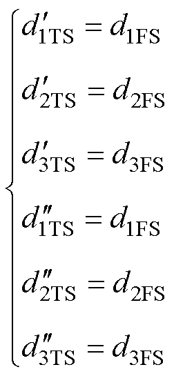 (27)
(27)
图7给出了基于PI-DPC的闭环ITPS策略控制框图。由于直接功率控制是以功率标幺值 进行建模,因此在每个采样周期内,将电压外环控制器的输出作为功率内环的输入,功率内环将当前时刻输入值进行标幺化,得到的标幺功率
 与上一时刻得到的标幺功率
 相减,判断其变化是否超过阈值,如果
 ,则认为系统未受到扰动,不需要进行暂态直流偏置抑制,此时通过
 计算移相比;如果
 ,则执行ITPS策略。首先通过式(10)计算出
 、
、 对应移相比,再通过式(4)判断其暂态运行模态,若运行在工况①,则根据式(16)确定暂态前半周期移相比,再根据
进行分类讨论确定暂态后半周期移相比。若变换器运行在工况②,则根据式(23)、式(24)确定暂态周期移相比;若变换器运行在工况③,则根据式(25)、式(26)确定暂态周期移相比,若变换器运行在工况④根据式(27)确定移相比。在每个开关周期内完成移相比更新计算,最后通过PWM驱动脉冲调制器产生驱动脉冲信号。另外,当DAB变换器输入输出为固定电压源时,只需功率环进行控制,其思路同理。
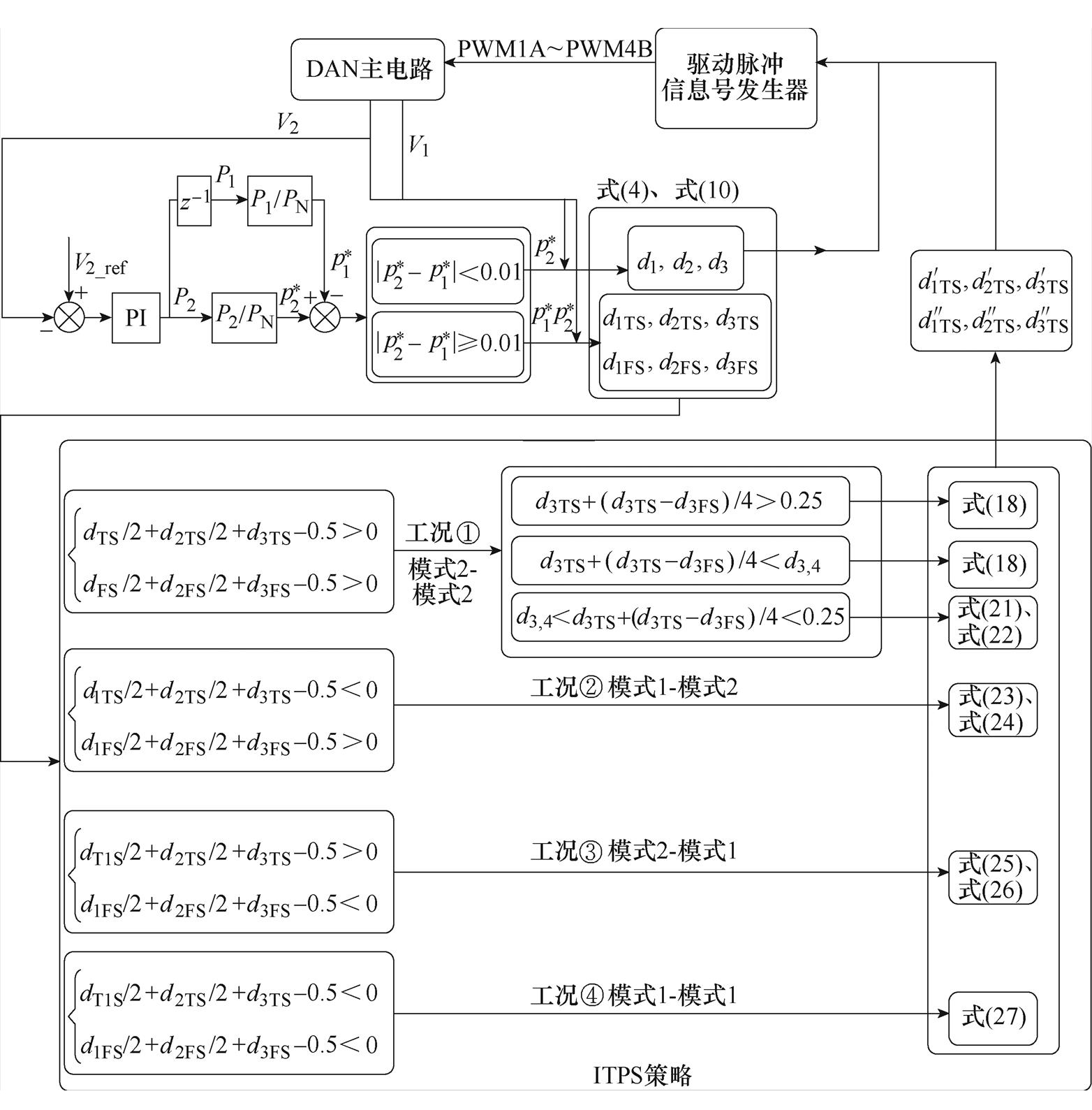
图7 ITPS策略控制框图
Fig.7 The strategy diagram of ITPS
为了验证所提出的ITPS策略的有效性,利用Matlab/Simulink搭建了DAB变换器仿真模型,仿真参数见表2。
表2 DAB仿真参数
Tab.2 Simulation parameters of DAB

参 数数 值 输入电压V1/V120 输出电压V2/V150 变压器电压比n11 开关频率fs/kHz20 变压器漏感L/mH60 电容Cin, Co/mF1 200 负载电阻R/W60~150
4.1.1 功率突变
固定输入电压120 V,输出电压150 V。图8~图10给出三种工况下传输功率突变时H桥电压和电感电流的仿真结果。图8代表工况①,功率在0.01 s从400 W阶跃至500 W;图9代表工况②,输出功率在0.01 s从200 W阶跃至600 W;图10代表工况③,输出功率在0.01 s从600 W阶跃至200 W。
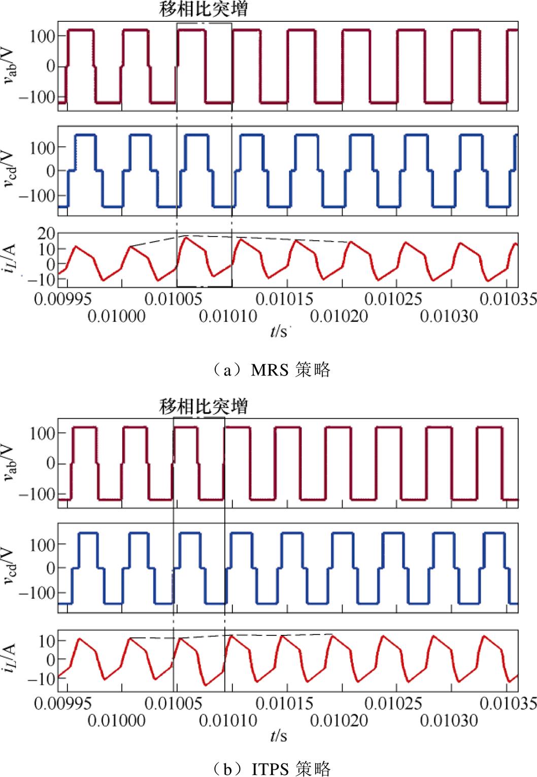
图8 工况①,功率突增时仿真结果
Fig.8 Simulation results of power increase of Case ①
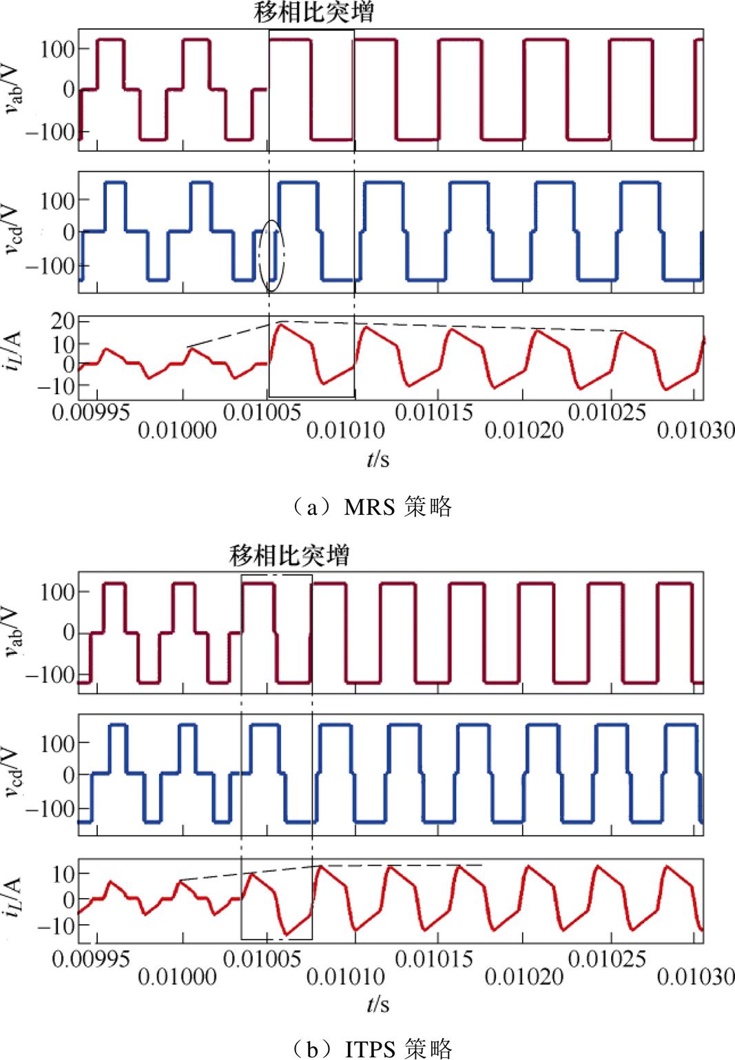
图9 工况②,功率突增时仿真结果
Fig.9 Simulation results of power increase of Case ②
图8~图10表明,三种工况下使用MRS策略,在功率变化瞬间,能观察到明显的暂态偏置电流,需要多次切换周期才能使DAB恢复到稳态,特别是功率增加时,电路中存在的电流尖峰可能会导致变压器和电感磁心饱和,对功率开关器件造成损害。图9a中,vcd窄脉冲的产生是由于移相角的突变,开关器件触发脉冲的占空比会出现暂时不对称。而变换器使用ITPS策略在过渡状态能够有效地抑制电流尖峰,使系统在一个周期内可以快速达到稳态。
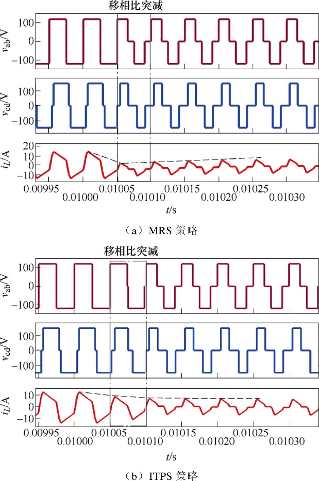
图10 工况③,功率突减时仿真结果
Fig.10 Simulation results of power decrease of Case ③
4.1.2 负载突变
图11给出输入电压120 V,通过PI-DPC动态调节输出电压150 V,负载电阻在0.25 s从150 W 切换至60 W 时MRS策略和ITPS策略下电感电流波形。相比于MRS策略,ITPS策略在启动阶段及负载切换时均能有效抑制电流尖峰,在DAB到达稳态时,ITPS策略与MRS策略具有相同的控制效果,可实现RMS电流最小。
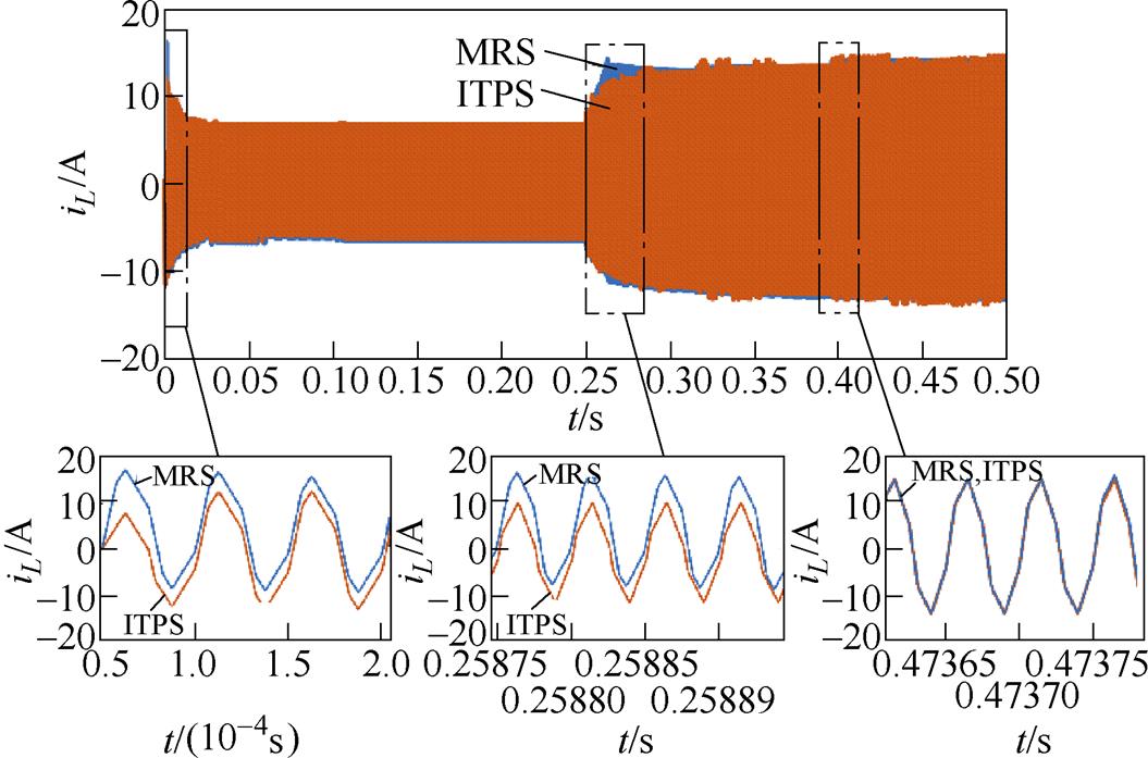
图11 负载突变时,DAB电感电流波形
Fig.11 DAB inductor current waveforms during sudden load changes
4.1.3 电感参数误差
实际电路中电感值与理论计算电感值可能存在一定误差,导致功率与实际功率值存在偏差,为验证电感参数对ITPS策略抑制暂态偏置效果的影响,图12给出了输出功率在0.01 s从400 W阶跃至500 W,电感值10 mH、300 mH时的MRS策略及ITPS策略下电感电流波形曲线。结果表明,在不同电感值的情况下,ITPS策略仍有较好的暂态偏置抑制效果,可以在一个周期内过渡到稳态。
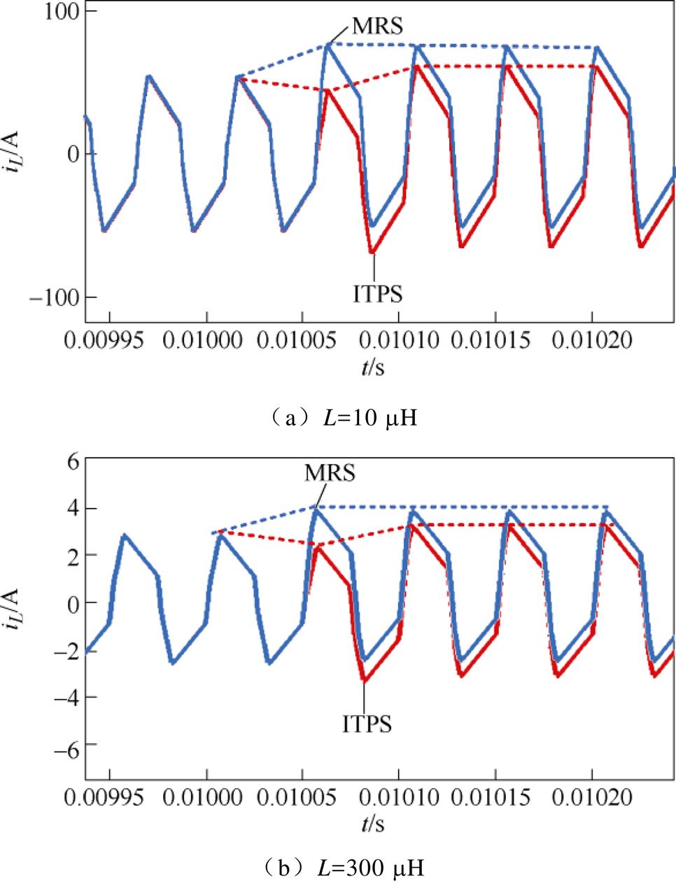
图12 电感电流波形
Fig.12 Waveforms of inductor current
4.1.4 死区时间影响
文献[22]分析了死区时间对DAB变换器的影响,当死区时间过大时会产生电压极性反转,可能产生直流偏置电流。功率突变及负载突变的仿真实验均将死区时间设置为0.5 ms(开关周期的1 %),为探究死区时间ITPS策略抑制暂态偏置效果的影响,图13给出了死区时间为5 ms(开关周期的10 %)情况下输出功率在0.01 s从400 W阶跃至500 W时MRS策略和ITPS策略下输出电压以及电感电流波形。结果表明,ITPS在死区时间较大的情况下仍具有有效性,相比于MRS策略能抑制暂态尖峰,快速到达稳态。
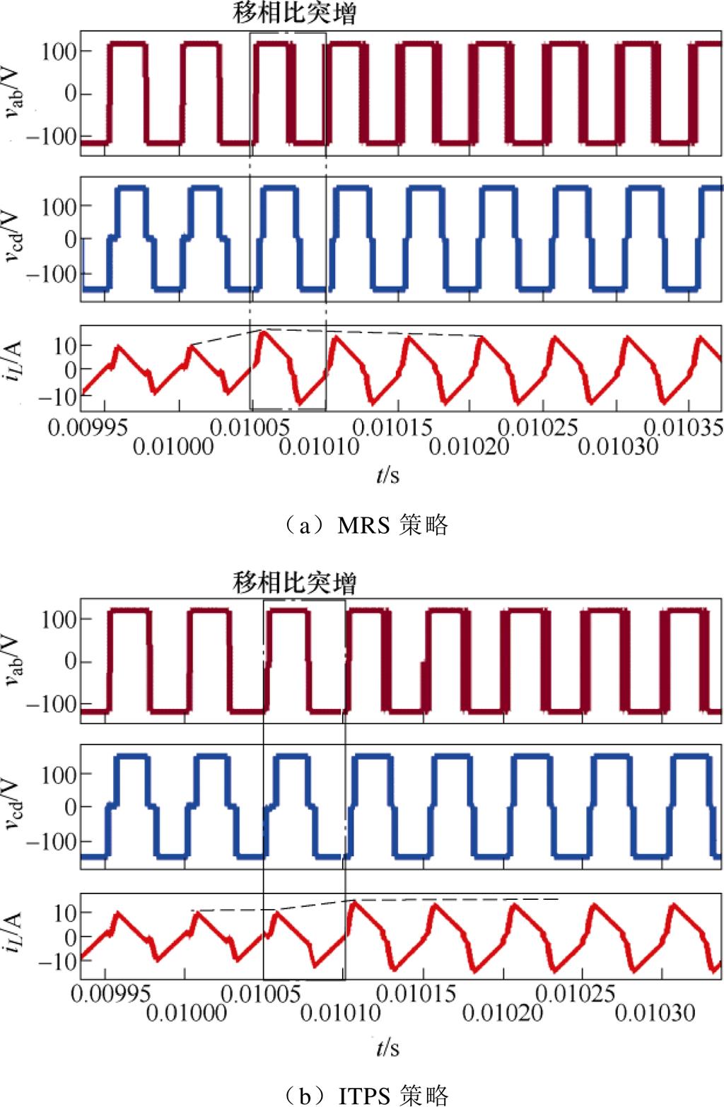
图13 死区时间影响下的暂态响应
Fig.13 Transient response under the deadtime
为了进一步验证所提出的ITPS策略的有效性,在实验室中搭建了实验平台,用示波器记录了主要的实验结果,包括输入、输出电压和电感电流等,实验参数与仿真参数相同,见表2。
4.2.1 功率突变
图14~图16给出了输入电压120 V,输出电压150 V三种工况下传输功率突变的实验结果。图14代表工况①输出功率从400 W阶跃至500 W,使用MRS策略和ITPS策略的实验结果。图15代表工况②,输出功率从200 W阶跃至600 W,使用MRS策略和ITPS策略的实验结果。图16代表工况③,输出功率从600 W阶跃至200 W,使用MRS策略和ITPS策略的实验结果。工况①输出功率突增时,MRS策略下DAB产生16 A峰值电流,暂态过程超过6个周期,ITPS策略电流峰值为11.5 A,一个周期内可过渡到稳态。工况②输出功率突增时,MRS策略电流峰值为19.7 A,暂态稳定时间将超过6个周期,ITPS抑制策略暂态过程电感电流峰值为13.2 A,一个周期内可过渡到稳态。工况③,传输功率突减时,虽不会产生峰值电流,但MRS策略下暂态过渡过程会大于4个开关周期,ITPS策略只需一个周期过渡到稳态。
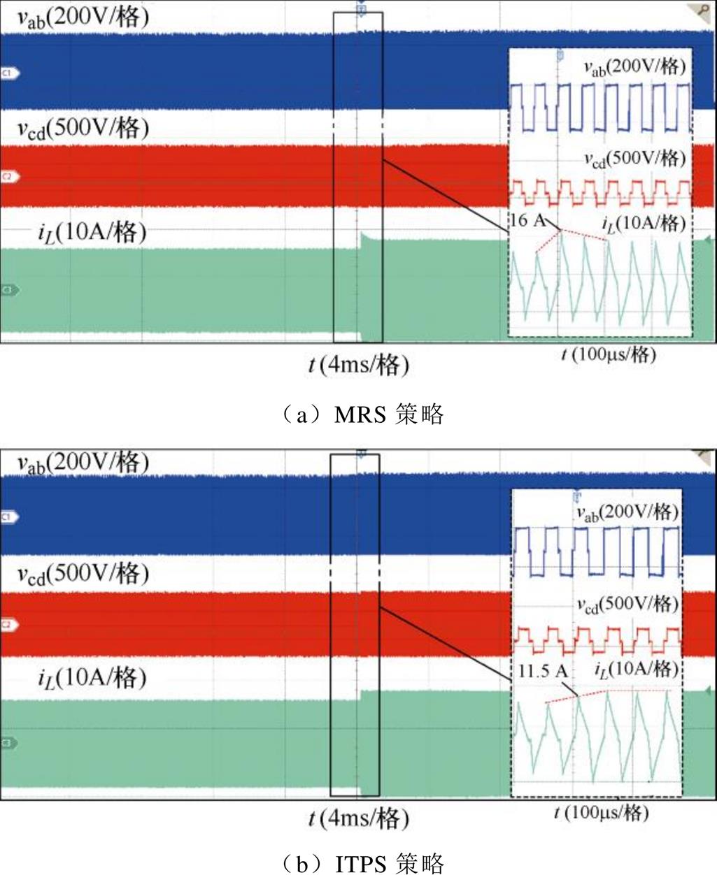
图14 工况①,功率突增时实验结果
Fig.14 Experimental results of power increase of Case ①
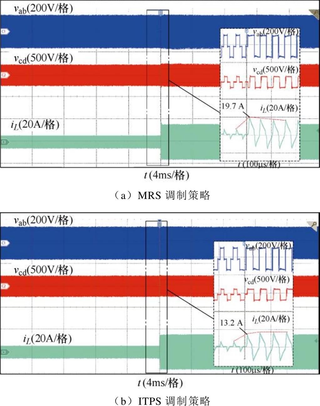
图15 工况②,功率突增时实验结果
Fig.15 Experimental results of power increase of Case ②
4.2.2 负载突变
图17给出PI-DPC下DAB变换器输入电压120 V,动态调节输出电压150 V,负载电阻由150 W 切换至40 W 时,输出电压和电感电流波形曲线。结果表明,MRS策略在负载切换时会产生较大的超调电流,电流峰值为17 A,ITPS策略将暂态开始周期的暂态电流抑制至9 A,有效地抑制了电流尖峰,改善电压闭环的暂态响应。
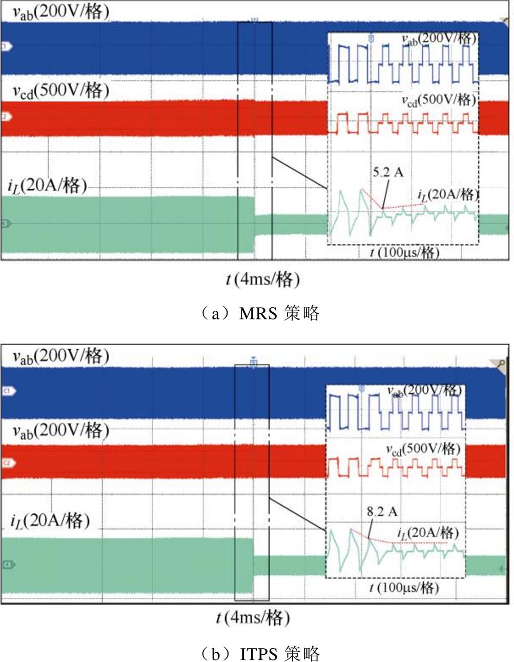
图16 工况③,功率突减时实验结果
Fig.16 Experimental results of power decrease of Case ③
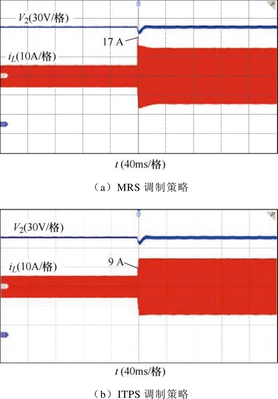
图17 负载突变时暂态响应
Fig.17 Transient response when the load change
4.2.3 ITPS稳态性能验证
为了验证ITPS策略在稳态工况下性能,图18给出了ITPS策略、FDM策略[13]、SPS策略下DAB效率、电感电流有效值曲线。结果表明,ITPS调制策略显著降低了RMS电流,并在低中功率水平效率提升更为明显。至此,所提出的ITPS策略在不同条件下的稳态和暂态过程的优化性能得到了验证。
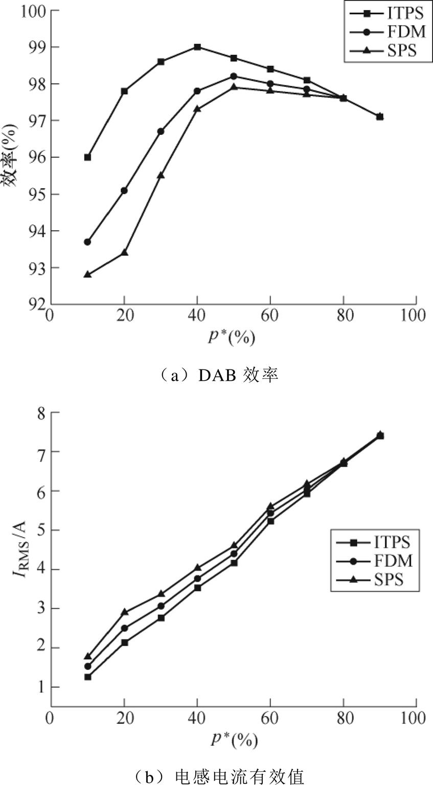
图18 ITPS、FDM、SPS策略下DAB效率、电感电流有效值曲线
Fig.18 DAB efficiency, inductor current RMS curves under ITPS, FDM, and SPS strategies
暂态直流偏置电流会导致变压器铁心深度饱和且电流峰值过大,影响DAB的可靠性。本文提出了一种基于直接功率控制的暂态直流偏置抑制策略来解决这一问题,建立了基于直接功率的DAB暂态直流偏置模型,对不同运行模式下的暂态偏置抑制策略进行分析,通过改变开关管在暂态周期中的占空比,有效抑制暂态过程的电流尖峰,使系统在一个周期内可以快速达到稳态,且无需增加额外的硬件电路,变压器漏感等偏差量对ITPS策略影响不大。与传统移相调制策略相比,ITPS策略在功率突变以及在输出电压动态调节,功率连续微小变化情况下都具有良好的暂态直流偏置抑制效果。仿真和实验结果表明,所提出的ITPS策略在稳态效率和对不同工况的适应性方面具有显著优势,具有一定的工程应用价值。
参考文献
[1] Zhao Biao, Song Qiang, Liu Wenhua, et al. Overview of dual-active-bridge isolated bidirectional DC-DC converter for high-frequency-link power-conversion system[J]. IEEE Transactions on Power Electronics, 2014, 29(8): 4091-4106.
[2] 雷志方, 汪飞, 高艳霞, 等. 面向直流微网的双向DC-DC变换器研究现状和应用分析[J]. 电工技术学报, 2016, 31(22): 137-147.
Lei Zhifang, Wang Fei, Gao Yanxia, et al. Research status and application analysis of bidirectional DC- DC converters in DC microgrids[J]. Transactions of China Electrotechnical Society, 2016, 31(22): 137- 147.
[3] 年珩, 叶余桦. 三端口隔离双向DC-DC变换器模型预测控制技术[J]. 电工技术学报, 2020, 35(16): 3478-3488.
Nian Heng, Ye Yuhua. Model predictive control of three-port isolated bidirectional DC-DC converter[J]. Transactions of China Electrotechnical Society, 2020, 35(16): 3478-3488.
[4] Esteban F D, Serra F M, De Angelo C H. Control of a DC-DC dual active bridge converter in DC microgrids applications[J]. Revista IEEE América Latina, 2021, 19(8): 1261-1269.
[5] Yang Xuan, Xu Yang, Chen Wenjie, et al. A three- level dual-active-bridge converter with blocking capacitors for bidirectional electric vehicle charger[J]. IEEE Access, 2019, 7: 173838-173847.
[6] Bai Hua, Nie Ziling, Mi Chunting. Experimental comparison of traditional phase-shift, dual-phase-shift, and model-based control of isolated bidirectional DC-DC converters[J]. IEEE Transactions on Power Electronics, 2010, 25(6): 1444-1449.
[7] Everts J, Krismer F, Van den Keybus J, et al. Optimal ZVS modulation of single-phase single-stage bidi- rectional DAB AC-DC converters[J]. IEEE Transa- ctions on Power Electronics, 2014, 29(8): 3954- 3970.
[8] Bal S, Yelaverthi D B, Rathore A K, et al. Improved modulation strategy using dual phase shift modulation for active commutated current-fed dual active bridge[J]. IEEE Transactions on Power Electronics, 2018, 33(9): 7359-7375.
[9] Wang Peng, Chen Xianzhong, Tong Chaonan, et al. Large and small signal average value modeling of dual-active-bridge DC-DC converter with triple- phase-shift control[J]. IEEE Transactions on Power Electronics, 2021, 36(8): 9237-9250.
[10] 吴俊娟, 孟德越, 申彦峰, 等. 双重移相控制与传统移相控制相结合的双有源桥式DC-DC变换器优化控制策略[J]. 电工技术学报, 2016, 31(19): 97-105.
Wu Junjuan, Meng Deyue, Shen Yanfeng, et al. Optimal control strategy of dual active bridge DC-DC converter with combined dual-phase-shift and traditional-phase-shift controls[J]. Transactions of China Electrotechnical Society, 2016, 31(19): 97-105.
[11] 王仁龙, 杨庆新, 操孙鹏, 等. 一种优化电流应力的双有源桥式DC-DC变换器双重移相调制策略[J]. 电工技术学报, 2021, 36(增刊1): 274-282.
Wang Renlong, Yang Qingxin, Cao Sunpeng, et al. An optimized dual phase shift modulation strategy for dual active bridge DC-DC converter[J]. Transactions of China Electrotechnical Society, 2021, 36(S1): 274-282.
[12] Tong Anping, Hang Lijun, Li Guojie, et al. Modeling and analysis of a dual-active-bridge isolated bidirectional DC/DC converter to minimize RMS current with whole operating range[J]. IEEE Transactions on Power Electronics, 2018, 33(6): 5302-5316.
[13] Choi W, Rho K, Cho B. Fundamental duty modulation of dual-active-bridge converter for wide range operation[J]. IEEE Transactions on Power Electronics, 2016, 31(6): 4048-4064.
[14] Liu Tao, Xu Yang, Chen Wenjie, et al. Design and implementation of high-efficiency control scheme of dual active bridge based 10kV/1MW solid state transformer for PV application[J]. IEEE Transactions on Power Electronics, 2019, 34(5): 4223-4238.
[15] Segaran D, Holmes D G, McGrath B P. Enhanced load step response for a bidirectional DC-DC con- verter[J]. IEEE Transactions on Power Electronics, 2013, 28(1): 371-379.
[16] Song Wensheng, Nie Hou, Wu Mingyi. Virtual direct power. control scheme of dual active bridge DC-DC converters for fast dynamic response[J]. IEEE Transa- ctions on Power Electronics, 2018, 33(2): 1750-1759.
[17] Dai Yong, Luo Suhua, Li Zhongwei. Direct power based control strategy for DAB DC-DC converter with cooperative triple phase shifted modulation[J]. IEEE Access, 2021, 9: 147791-147800.
[18] Zhao Biao, Song Qiang, Liu Wenhua, et al. Transient DC bias and current impact effects of high- frequency-isolated bidirectional DC-DC converter in practice[J]. IEEE Transactions on Power Electronics, 2016, 31(4): 3203-3216.
[19] 余雪萍, 涂春鸣, 肖凡, 等. 三端口隔离DC-DC变换器的暂态直流偏置机理及抑制策略[J]. 电工技术学报, 2020, 35(9): 1962-1972.
Yu Xueping, Tu Chunming, Xiao Fan, et al. Transient DC bias mechanism and suppression strategy of the three-port isolated DC-DC converter[J]. Transactions of China Electrotechnical Society, 2020, 35(9): 1962-1972.
[20] Dai Tianlin, Qin Jianggang, Ge Gao, et al. Research on transient DC bias analysis and suppression in EPS DAB DC-DC converter[J]. IEEE Access, 2020, 8(6): 1421-61432.
[21] Bu Qinglei, Wen Huiqing, Wen Jiacheng, et al. Transient DC bias elimination of dual-active-bridge DC-DC converter with improved triple-phase-shift control[J]. IEEE Transactions on Industrial Elec- tronics, 2020, 67(10): 8587-8598.
[22] Zhao Biao, Song Qiang, Liu Wenhua, et al. Dead-time effect of the high-frequency isolated bidirectional full-bridge DC-DC converter: comprehensive theo- retical analysis and experimental verification[J]. IEEE Transactions on Power Electronics, 2014, 29(4): 1667-1680.
Abstract The dual active bridge (DAB) has the advantages of bidirectional energy flow, low voltage and current stress of switching devices, input-output galvanic isolation, high power density, and soft switching. Thus, it is widely used in electric vehicles, DC distribution networks, microgrids, distributed energy, and other fields. When the input voltage changes or the load changes suddenly, the DAB converter will generate a transient DC bias current on the primary side of the transformer, leading to problems such as excessive primary current peak value and saturation of the transformer core. The improved triple phase shift (ITPS) control strategy based on direct power control is proposed to eliminate the DAB transient DC bias current.
Firstly, the RMS optimization strategy based on multiple harmonic minimizations is reviewed, and the direct power control model of DAB under this strategy is deduced. Secondly, the transient DC bias current of different cases is analyzed, and the phase shift ratio combination scheme for suppressing the transient DC bias current is determined. When the DAB operation mode is changed, the duty cycle of the MOSFET in the transient period is adjusted to maintain the volt-second balance of the transformer. Then, when the DAB converter is used as a DC power supply, the transmission power and output voltage should be controlled. Since the relationship between the shift ratio and the transmission power is non-linear, the shift ratio cannot be directly determined by the voltage loop output. Therefore, combined with the power inner loop, the control method of the voltage outer loop based on the PI strategy is determined to realize the dual-loop control. Finally, a DAB converter prototype is built to verify the effectiveness of the proposed strategy. The experimental results show that when the transmission power steps within the heavy load range, the ITPS strategy shortens the transition time from six cycles to one cycle and reduces the peak value of transient current from 16 A to 11.5 A. When the transmission power steps from light load to heavy load, the ITPS strategy shortens the transition time from six cycles to one cycle and reduces the peak value of transient current from 19.7 A to 13.2 A. When the transmission power steps from heavy load to light load, there will be no current spike in the transient process, and the ITPS strategy shortens the transition time from four cycles to one cycle.In addition, compared with the SPS and FDM strategies, the ITPS strategy can reduce the RMS current by 18.5 % and effectively improves efficiency.
The following conclusions can be drawn from the simulation and experimental results: (1) Compared with the traditional modulation strategy, the ITPS strategy can effectively suppress the transient bias current and shorten the transient process. (2) The ITPS strategy combines the dynamic performance of DAB with the optimization of steady-state performance, which can achieve a fast transient response while ensuring the optimization of the current RMS.
keywords:Transient DC bias, dual active bridge (DAB), improved triple-phase shift, root mean square (RMS) current
DOI: 10.19595/j.cnki.1000-6753.tces.220896
中图分类号:TM46
收稿日期 2022-05-23
改稿日期 2022-06-01
刘子薇 女,1998年生,硕士,研究方向为双有源桥 DC-DC 变换器控制技术与应用。E-mail: 997062998@qq.com
刘宝龙 男,1988年生,博士,讲师,研究方向为微电网协调与控制。E-mail: liubaolong@126.com(通信作者)
(编辑 陈 诚)