 ,
, 为直流侧总电压。
摘要 对于中点钳位型三电平逆变器(NPC TLI),一般通过单调制波与双载波相比较的方式产生脉冲序列,即基于载波的脉宽调制(CBPWM)。然而,该方法在高调制度低功率因数条件下中点电位(NPV)会出现三倍频波动。针对此问题,该文介绍一种简便的调制波分解方法,并以无条件实现NPV平衡的虚拟空间矢量脉宽调制(VSVPWM)为例说明该方法的可行性。在此基础上,提出一种可同时实现NPV平衡和开关损耗降低的调制策略。该调制策略具有四种模式,因此,将其命名为FM_VSVPWM。此外,对比了FM_VSVPWM与CBPWM、VSVPWM的调制性能。最后,通过实验验证了FM_VSVPWM的有效性和优越性。
关键词:中点钳位型三电平逆变器 调制波分解 中点电位平衡 开关损耗 调制策略
随着电力电子技术的发展,中点钳位型三电平逆变器(Neutral Point Clamped Three-Level Inverter, NPC TLI)受到了广泛关注[1-4]。相对于两电平逆变器,NPC TLI具有总谐波失真率小、开关器件应力低以及电磁干扰小的优势[4]。因此,NPC TLI被广泛应用于中高压变频调速、电力系统无功补偿、可再生能源并网发电等领域[5]。
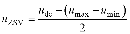
中点电位(Neutral Point Voltage, NPV)平衡是NPC TLI正常运行的重要保障[6]。在调制过程中,当中点电流不为零时,对电容进行充放电,导致直流侧NPV不平衡[7]。不平衡的NPV可能产生较高的电压应力,造成开关器件损坏。为解决上述问题,许多NPV平衡方法被陆续提出。一般使用脉冲宽度调制(Pulse Width Modulation, PWM)方法控制NPV平衡,可分为基于载波PWM(Carrier Based PWM, CBPWM)和基于空间矢量PWM(Space Vector PWM, SVPWM)[8-10]。文献[9-10]研究了CBPWM与SVPWM的等效关系。通过对CBPWM注入合适的零序电压(Zero Sequence Voltage, ZSV)即可得到与SVPWM相同的脉冲序列。CBPWM在工业领域由于其原理简单、容易实现被广泛应用,但是在高调制度低功率因数条件下,采用CBPWM,直流侧电容电压会出现三倍频波动。为解决上述问题,文献[11]提出一种基于虚拟空间矢量(Virtual Space Vector, VSV)的PWM方法,即VSVPWM。这种调制策略通过使用冗余小矢量控制NPV的偏移,达到无条件实现NPV平衡的目的。但是这种调制策略将增加开关损耗,算法也较复杂。文献[12]提出了一种基于ZSV注入法和调制波分解实现NPV平衡的混合调制策略。该方法对CBPWM注入ZSV实现NPV平衡,当ZSV注入法失效时,对中间相调制波进行分解,产生双调制波,通过调节双调制波控制1电平作用时间来实现NPV平衡。但该方法使用PI调节器进行NPV主动控制,在某些极端条件下PI调节器会失效。文献[13]提出一种基于双调制波的CBPWM策略,可消除NPC TLI的NPV振荡,但是该方法通过计算占空比的方式得到双调制波,过程复杂。
变换效率是评价NPC TLI性能的一项重要指标。NPC TLI在运行过程中的能量损耗主要分为传导损耗和开关损耗。对于不同调制方式,传导损耗几乎一致,因此通常重点关注开关损耗,文献[14]提出了一种改进型VSVPWM,对NPV主动控制进行了优化,同时,通过选用具有低共模电压(Common Mode Voltage, CMV)的矢量以抑制CMV。近年来,VSVPWM方法不断被改进,但是开关损耗大这个问题一直没有得到很好地解 决[14-17]。为降低开关损耗,文献[18]提出一种基于载波的非连续脉宽调制(Discontinuous PWM, DPWM)。该方法对调制波注入ZSV,通过钳位方式避免开关动作,但在一定程度上牺牲了NPV控制能力。文献[19]提出一种降低CMV的基于载波的DPWM方法,该方法通过注入合适的ZSV进行钳位,降低了开关损耗,同时通过选取合适的载波来降低CMV。
上述调制策略大多采用单调制波双载波的方式产生脉冲序列。受文献[12-13]启发,本文介绍了一种简易的调制波分解方法,并对载波进行了优化。基于VSVPWM和调制波分解,提出一种可同时实现NPV平衡和降低开关损耗的调制策略,该方法在调制过程中共有四个模式可进行切换,因此,将其命名为FM_VSVPWM。实验结果验证了所提方法的有效性和优越性。
NPC TLI拓扑结构如图1所示。每相由4个带有反并联二极管的IGBT S1~S4以及两个钳位二极管VD1、VD2组成,C1、C2为直流侧电容,当电容电压均衡时,,为直流侧总电压。
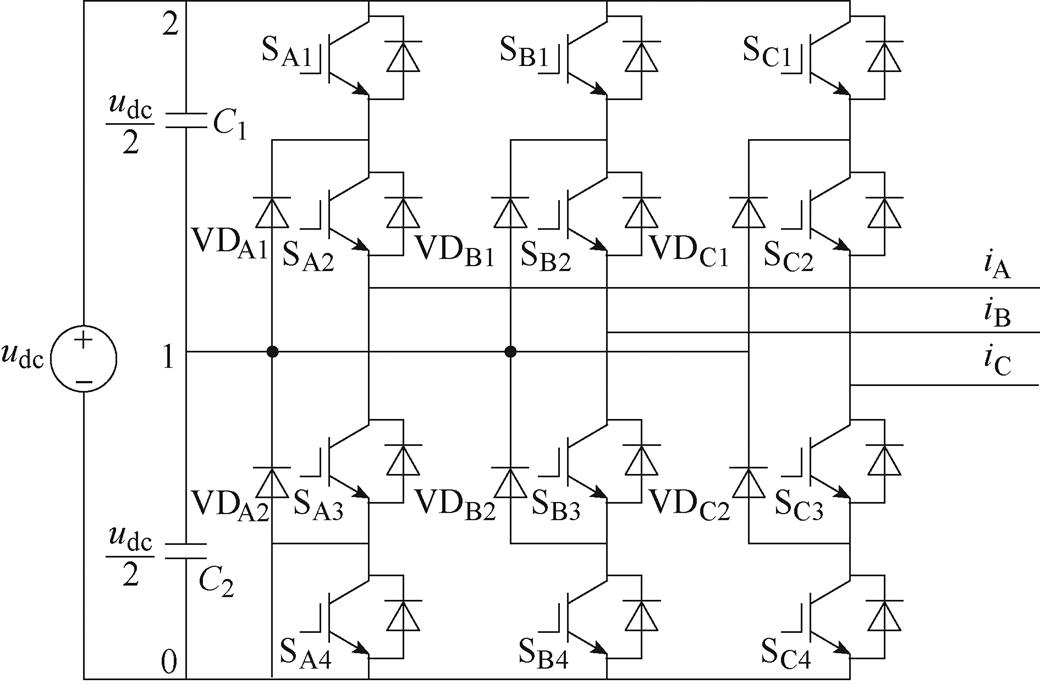
图1 NPC TLI拓扑结构
Fig.1 Topology of NPC TLI
选择电容中点作为参考点,当S1和S2导通时,输出电压为 ,定义该状态为2电平;当S2和S3导通时,输出电压为0,定义该状态为1电平;当S3和S4导通时,输出电压为
 ,定义该状态为0电平。
 、
、 、
、 和
和 、
、 、
、 分别为三相调制电压、输出电流。三相调制电压可表示为
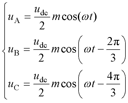 (1)
(1)
式中,wt为A相的相位;m为调制度,m∈[0, 1.15]。三相输出电流为
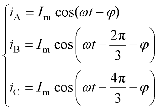 (2)
(2)
式中, 为相电流的峰值;j 为功率因数角。
为便于分析,将三相电压重新排列得到
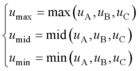 (3)
(3)
将排列后的 、
、 、
、 对应的相电流分别记为
 、
、 、
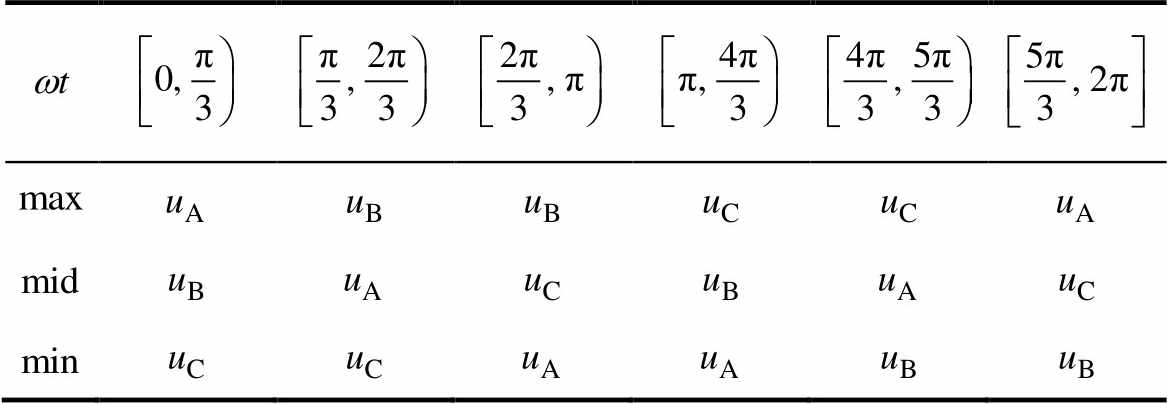
、 。在不同相位下,三相电压的大小关系见表1。
表1 不同相位下三相电压的大小关系
Tab.1 Relationship among three-phase voltages under different phase angles
NPC TLI一般采用单调制波双载波方法生成脉冲序列如图2所示。以同相三角载波为例,v1和v2分别为0~与 ~0的三角载波。将调制电压
 与三角载波比较,输出序列
 可描述为
可描述为
 (4)
(4)
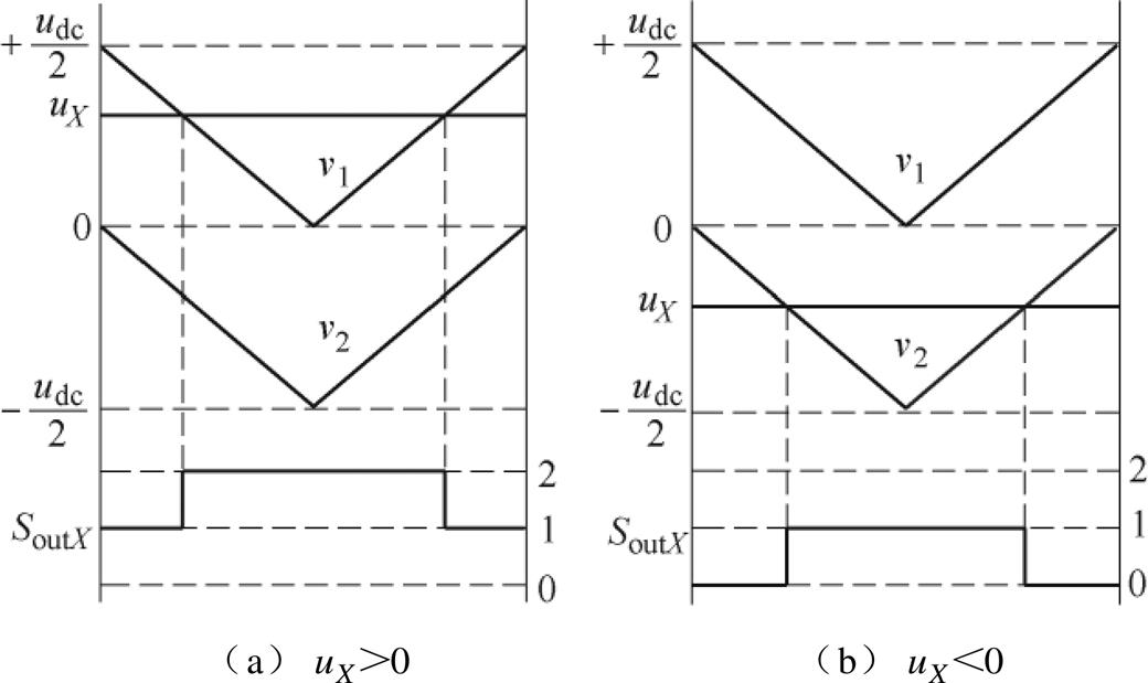
图2 单调制波双载波产生输出序列
Fig.2 The output sequence is generated by double carrier and single modulation wave
由图2可知,采用单调制波双载波的调制方法,不论是 还是
还是 ,三相输出序列每相不多于两个电平,最多只有一次开关动作。
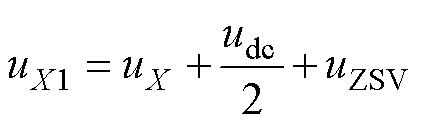
在单调制波双载波的调制方法中,首先需要判断调制波的极性。调制波分解产生输出序列如图3所示,为了消除调制电压的负值,将三相调制电压同时增加 ,即以负母线作为参考点,且向三相注入大小为
 的ZSV可得
 (5)
(5)
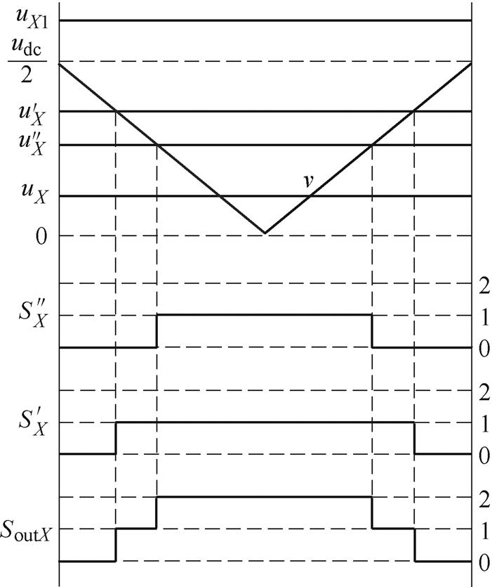
图3 调制波分解产生输出序列
Fig.3 Output sequence generated by modulation wave decomposition
修正后的相电压 。将
。将 分解成两个调制电压
 和
和 ,且满足
,且满足
 (6)
(6)
将式(5)代入式(6)得
 (7)
(7)
式中, ,且
,且 。
。
将、分别与0~的三角载波v比较,生成由0、1组成的两个PWM序列 、
、 ;将、相加得到输出序列。
在双调制波单载波模式下,三相输出序列二、一、零电平的占空比分别为
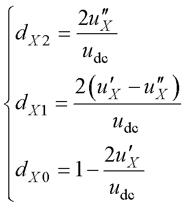 (8)
(8)
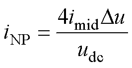
分析NPC TLI拓扑可知,仅当某相的输出为1电平时,该相才会从电容中点抽取或者注入电流,因此,中点电流iNP为
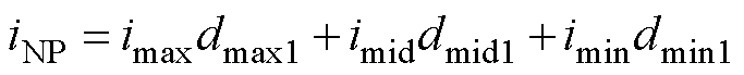 (9)
(9)
式中, 、
、 、
、 为对应相1电平的占空比。假设在一个载波周期内注入中点的三相电流之和为0,即
 ,结合式(8)和式(9)可得
 (10)
(10)
由此可知,调制波、在进行功率交换时三相瞬时功率之和保持不变。
传统CBPWM方法中每相对应一个调制波。双调制波单载波模式下每相对应两个调制波,若限制其中一个调制波,则可与传统CBPWM一致。采用的限制规则为
 (11)
(11)
根据CBPWM中间相的极性可分为两种调制模式。
1)CBPWM1: ,
, ,
,
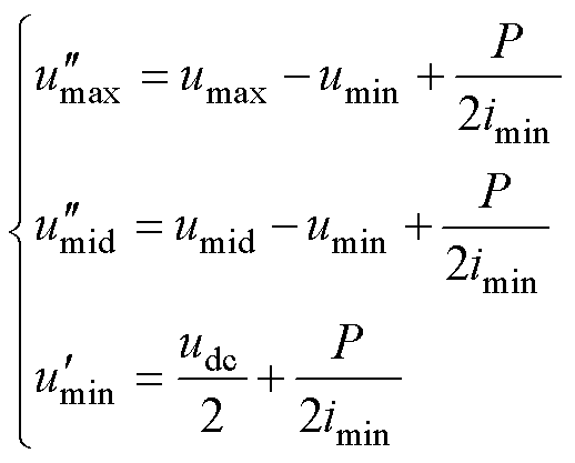
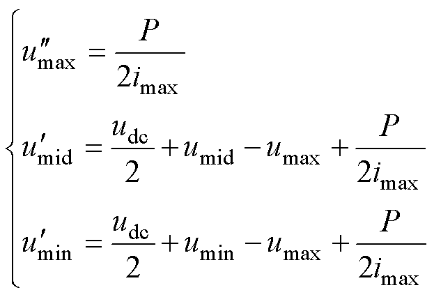
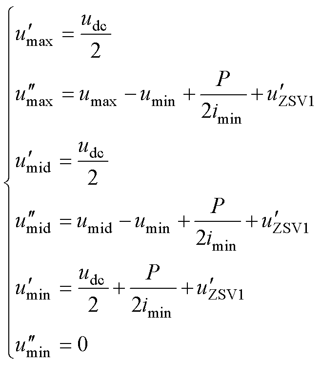
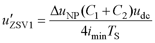
由式(11)可得被限制的调制波分别为
 (12)
(12)
结合式(7)、式(10)和式(12)可得为
 (13)
(13)
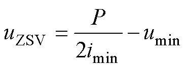
式中,P为三相总功率,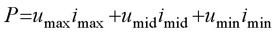 。
。
将式(12)和式(13)代入式(7)可得未被限制的3个调制波分别为
 (14)
(14)
2)CBPWM2:, ,
,
类比于CBPWM1,可得为
 (15)
(15)
同理,未被限制的3个调制波分别为
 (16)
(16)
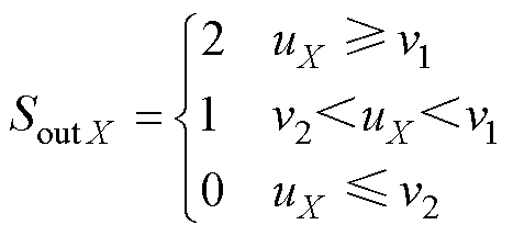
对于任意符合要求的ZSV,若由式(9)确定的中点电流在一个工频周期内的平均值为零,则可实现NPV平衡。图4分别给出了不同功率因数角下,CBPWM在m∈[0, 1.15]、wt∈[0, 2p/3]范围内可实现NPV平衡的区域。
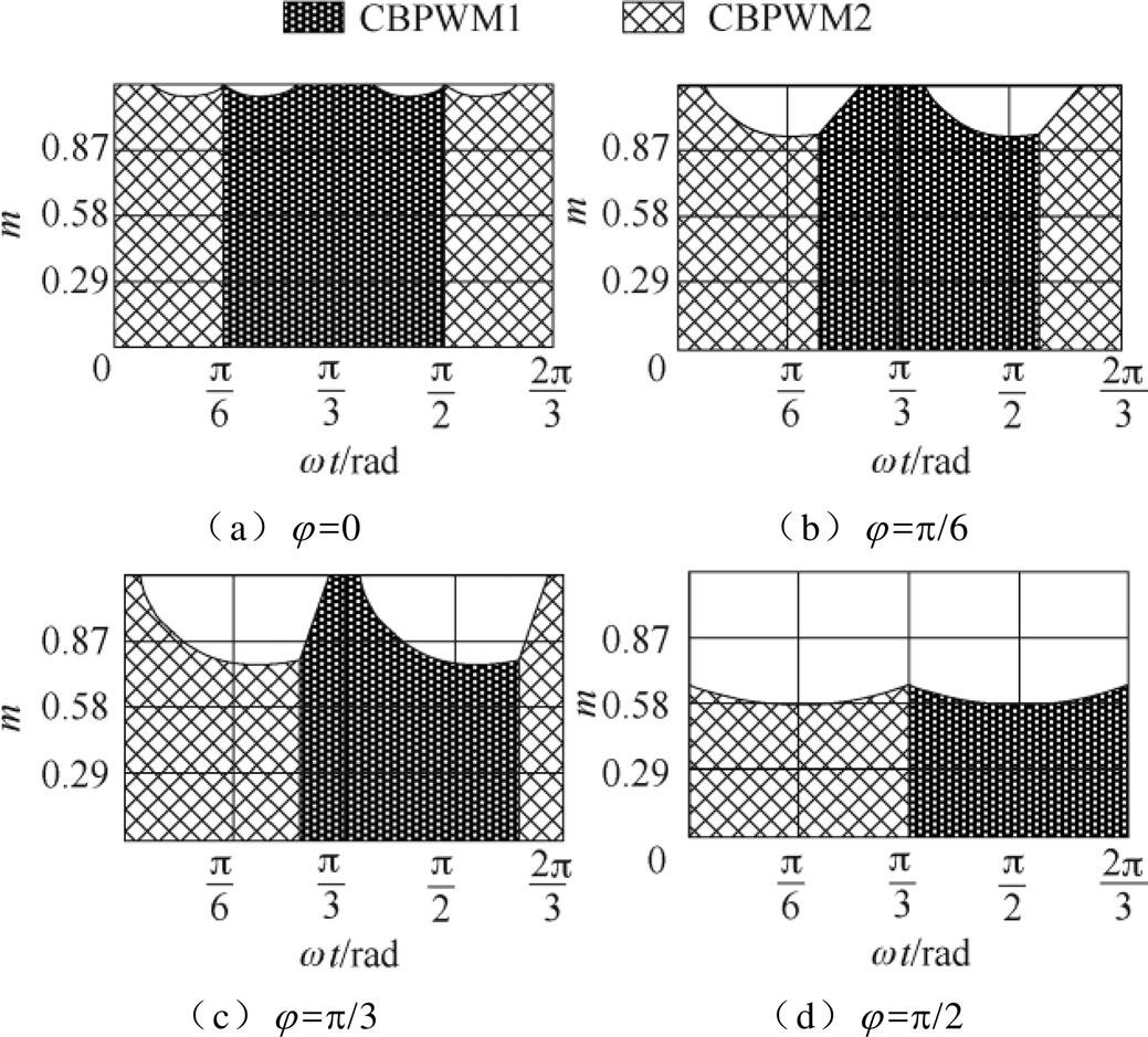
图4 不同功率因数角下CBPWM的可适用区域
Fig.4 Applicable area of CBPWM under different power factor angles
图4中,当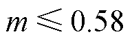 时,CBPWM在
 范围内可实现NPV平衡;当
 时,随着j 从0增加到
 ,在CBPWM下可实现NPV平衡的区域逐渐减少。这是因为的注入需要满足限制条件
 。当调制度m较大时,需要注入的过大,使得、不再满足这一限制条件。因此,CBPWM不能在全功率因数全调制度范围内实现NPV平衡。
VSVPWM具有无条件实现NPV平衡的优势,其对三相占空比做如下限制
 (17)
(17)
将式(8)代入式(17)可得双调制波的限制条件为
 (18)
(18)
整理得到
 (19)
(19)
结合式(7)、式(19)可得三相双调制波为
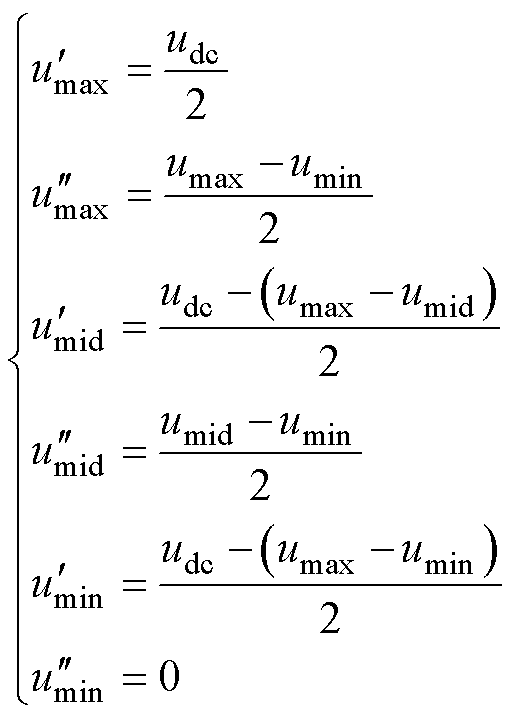 (20)
(20)
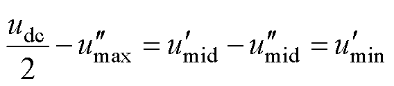
对比式(20)与传统VSVPWM计算占空比方式得到的调制波,发现两者完全相同。因此上述基于调制波分解的调制策略实质上就是VSVPWM,可实现NPV无条件平衡。在任意载波周期内,该调制方式最大相和最小相各有1次开关动作,中间相有2次开关动作,共有4次开关动作,相比于CBPWM的3次开关动作,开关损耗增加。
三相输出电压每相均含有2个调制波,共有6个调制波,即自由度为6。由式(18)可看出,基于调制波分解的VSVPWM中已经限制了 和
和 。若要继续降低开关次数,可分别限制其他4个调制波。
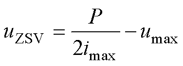
为避免最大相的一次开关动作,将调制波 钳位至
钳位至 ,则注入的ZSV为
 (21)
(21)
需要注意的是,中间相的两个调制波均可变化,因此无法确定向 、
、 注入的ZSV分量。为解决上述问题,引入ZSV的分配系数k,限定向、注入的ZSV分量分别为
 、
、 。因此三相双调制波变为
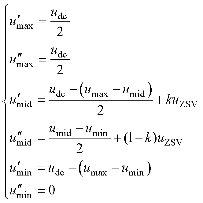 (22)
(22)
结合式(8)、式(9)和式(22)可得中点电流为
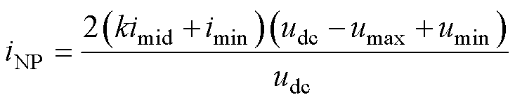 (23)
(23)
显然式(23)中, 。因此使得成立的k值为
 (24)
(24)
若 ,则该方式将具有与VSVPWM完全相同的NPV特性,且开关次数减少。
将式(24)代入式(22)可得三相双调制波为
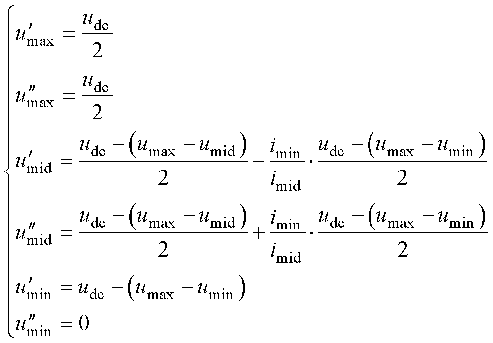 (25)
(25)
将此调制方式定为模式1。类比模式1的调制波求解过程,分别对 、、钳位得到相应的调制波,见表2。调制策略由四个模式组成,因此将其命名为FM_VSVPWM。
表2 FM_VSVPWM各模式的双调制波
Tab.2 Modulation waves of each mode in FM_VSVPWM
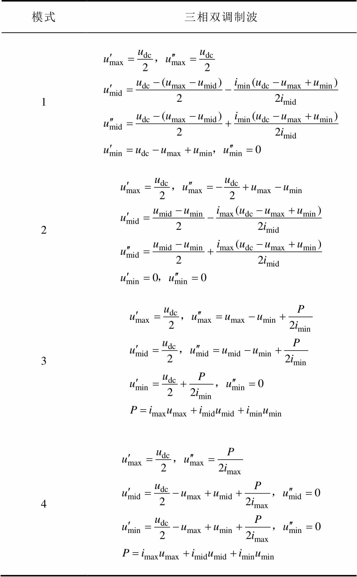
模式三相双调制波 1 2 3 4
对比模式3、4的调制波与CBPWM的调制波,发现模式3、4分别和CBPWM1、CBPWM2完全一致。因此,当 时,模式3、4可在全功率因数范围内实现NPV平衡。模式1和模式2为基于VSVPWM衍生出的两种新的调制模式。
四种模式下的三相电平情况见表3,不同模式下输出序列如图5所示。
表3 各模式的三相电平
Tab.3 Three phase level under each mode
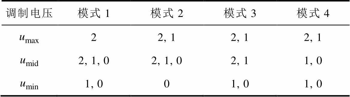
调制电压模式1模式2模式3模式4 22, 12, 12, 1 2, 1, 02, 1, 02, 11, 0 1, 001, 01, 0
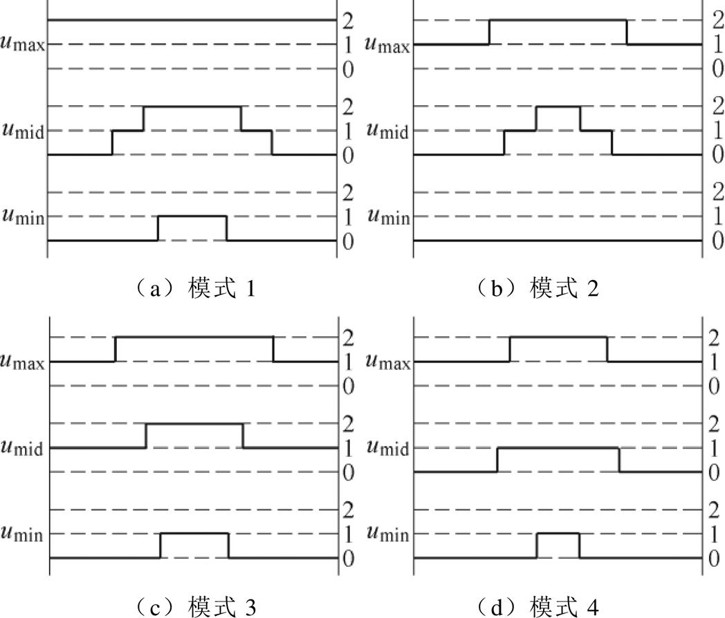
图5 不同模式下输出序列
Fig.5 Output sequence under different modes
由表3可知,在每一个载波周期内,模式1~4都只有3次开关动作。相对于VSVPWM的4次开关动作,模式1~4开关次数减少,开关损耗将降低。
值得注意的是,式(24)的适应范围将受电流影响,即功率因数将影响模式1~4的可适用区间。不同功率因数下各模式的可适用区间如图6所示。由于 、
、 、
、 的变化周期为
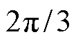 ,此处只分析
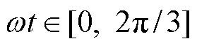 范围内各模式的可适用区间。
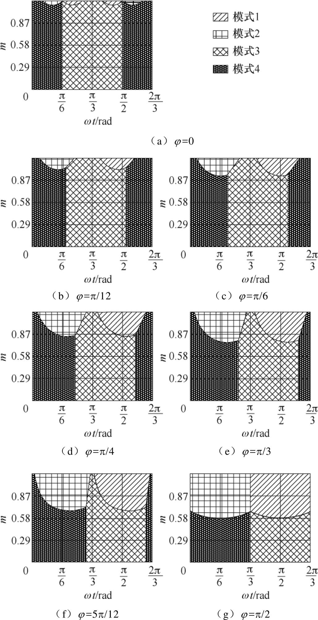
图6 不同功率因数角下四种模式的可适用区域
Fig.6 Applicable areas of four modes under different power factor angles
由图6可知,在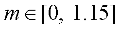 ,范围内,不同功率因数角下各模式的可适用区间不同。当
 时,模式3和模式4基本上占据整个调制度区间。模式1和模式2仅在接近
 的部分区域可适用。随着
 的增加,模式1和模式2的可适用区间逐渐增加,模式3和模式4的可适用区间逐渐减少。当
 时,模式3和模式4的可适用区间达到最小,模式1和模式2的可适用区间达到最大。除此之外,在j 相同时,任意一工作点
 只对应某一种模式,即模式1~4的可适用区间互补且恰好完全覆盖整个区域。因此模式1~4可实现全调制度全功率因数范围内NPV平衡。
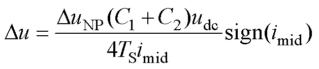
模式1~4中的双调制波是基于单载波周期NPV平衡得到的,理论上NPV在一个载波周期内的变化量为零,然而实际中死区的插入、上下电容容值的偏差都会造成NPV不平衡。为尽可能减少这些不利因素的影响,需要采用NPV主动控制方法。
当NPV不平衡时,上下电容电压偏移量
 。定义中点电流流出为正,为抵消上下电容电压差值,在一个基波周期内需要补偿的中点电流平均值为
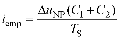 (26)
(26)
式中, 为载波周期。为平衡NPV,令中点电流与补偿电流相等,即
 (27)
(27)
CBPWM中,三相双调制波每相均有一个调制波被限制,另一个调制波可变化。因此可对变化的调制波注入ZSV实现对NPV的控制。
对于CBPWM1, 、
、 、
、 被限制。因此对
 、
、 、
、 注入大小为
注入大小为 的ZSV得到
 (28)
(28)
结合式(8)、式(9)、式(26)~式(28)得
 (29)
(29)
类比CBPWM1,CBPWM2需要注入的 为
为
 (30)
(30)
模式1和模式2均有一相被钳位,ZSV注入法已经不再适用,需要使用其他方法来实现NPV控制。
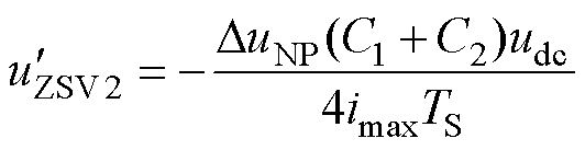
以模式1为例,由于最大相被钳位至2电平且要保证线电压关系不变,只能改变中间相。模式1、模式2的NPV主动控制方法如图7所示,调制波 、
、 产生输出序列
 ,、分别向上和向下平移
 得到
得到 、
、 ,产生的输出序列为
 。结合式(7)可得最大相与中间相的线电压在变换前后分别为
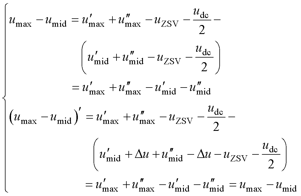 (31)
(31)
由此可知,中间相调制波在变换前后,三相间的线电压关系保持不变。
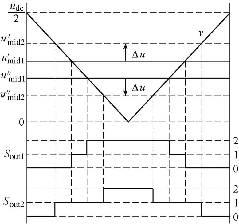
图7 模式1、2的NPV主动控制方法
Fig.7 Active NPV control method of mode 1 and mode 2
在中间相调制波变换前,有 成立。因此,在变换后,可得中点电流为
 (32)
(32)
结合式(26)、式(27)和式(32)可得双调制波的变化量为
 (33)
(33)
式中,sign(·)为符号函数。
在实际中,相对于调制电压来说很小,甚至可以忽略不计。
不同PWM策略的传导损耗大致相同,而开关损耗却有很大差异,因此,开关损耗成为衡量调制策略性能的一项重要指标。假设在一个基波周期内相电流幅值保持不变,根据三相输出序列中每相的开关次数和电流大小可计算出不同调制度和功率因数下FM_VSVPWM、CBPWM以及VSVPWM的开关损耗,分别记为PSL_FM、PSL_CB和PSL_VSV。为了便于评估开关损耗,图8给出了全调制度和功率因数范围内PSL_VSV/PSL_CB、PSL_FM/PSL_CB和PSL_FM/ PSL_VSV的值。
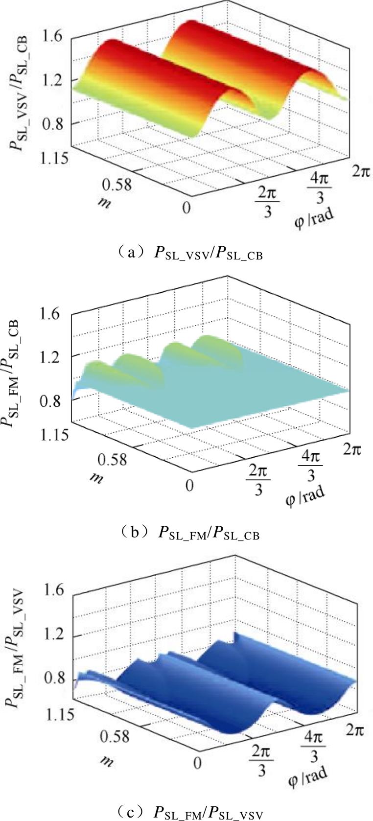
图8 不同调制策略开关损耗比较
Fig.8 Comparison of switching loss under different modulation strategies
图8a中,在一个基波周期内,PSL_VSV/PSL_CB的值始终大于1.13。这意味着在全调制度和全功率因数范围内,VSVPWM的开关损耗始终比CBPWM的开关损耗大。这是由于VSVPWM有4次开关动作,而CBPWM只有3次开关动作。在全调制度范围内,当、 和
和 时,PSL_VSV/PSL_CB达到最小值1.13;当和
 时,PSL_VSV/ PSL_CB达到最大值1.5。
图8b中,当时,PSL_FM/PSL_CB的值为1,这种情况下FM_VSVPWM仅选择CBPWM1和CBPWM2。当, (n=0, 1, 2)时,PSL_FM/PSL_CB达到最小值0.8;当,
 (n=1, 3, 5, 7)时,PSL_FM/PSL_CB达到最大值1.13。
图8c中,给出了不同运行条件下PSL_FM/PSL_VSV的值。可以看出,PSL_FM/PSL_VSV的值始终小于0.88。这意味着在全调制度和功率因数范围内FM_ VSVPWM的开关损耗始终比VSVPWM的开关损耗小。当 且(n=0, 1, 2)时,PSL_FM/ PSL_VSV达到最大值0.88;当和时,PSL_FM/PSL_VSV达到最小值0.67。在
 区域中,模式1、2参与调制过程,导致PSL_FM/PSL_VSV的值变得较为复杂。
输出电压的谐波特性可用加权总谐波失真VWTHD来评价。VWTHD可表示为
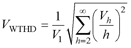 (34)
(34)
式中,V1和Vh分别为输出电压的基波分量和第h次谐波分量。不同功率因数和不同调制度下,不同调制策略的VWTHD变化情况如图9所示。
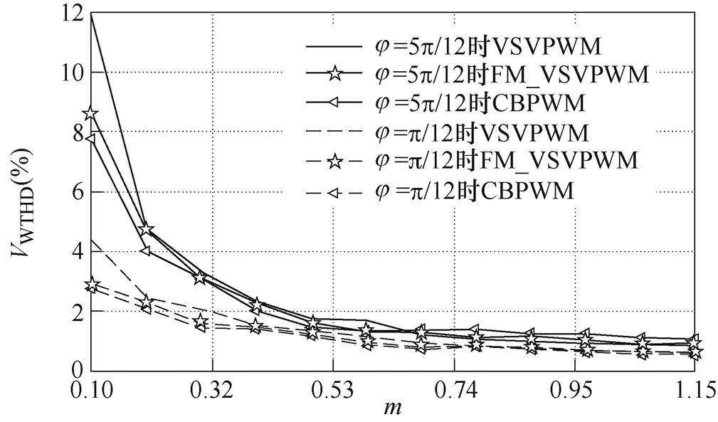
图9 不同调制策略下VWTHD随m的变化曲线
Fig.9 Variation curves of VWTHD with m under different modulation strategies
图9中,随着m的增大,不同调制策略下的VWTHD均呈下降趋势。此外,当功率因数角增大时,VWTHD也相应增大。在低调制度范围内,FM_ VSVPWM的VWTHD大于CBPWM而小于VSVPWM。在高调制度范围内,FM_VSVPWM的VWTHD大于VSVPWM而小于CBPWM。这是由于在低调制度时,三种调制策略均能实现NPV平衡,低频特性差异不大,而VSVPWM的高频特性较差,导致VSVPWM的VWTHD最大;而在高调制度时,CBPWM的NPV波动较大,导致其低频特性较差,因此CBPWM的VWTHD最大。
为了验证本文提出的FM_VSVPWM的有效性,搭建了NPC TLI的实验平台,如图10所示。图中,交流源在单相不控整流桥的作用下产生稳定的直流电压,为逆变器提供直流输入,逆变器所带负载为阻感性负载。本文进行了不同调制度和功率因数下的CBPWM、VSVPWM和FM_VSVPWM实验。实验包括稳态实验、NPV恢复实验和动态实验。与实验相关的系统参数见表4。在稳态实验和NPV恢复实验中,采用表4中的负载1~4以确保不同调制度和功率因数下相电流幅值不变。采用负载4和负载5进行负载突变实验。
图11~图13分别给出了不同调制度和功率因数下CBPWM、VSVPWM和FM_VSVPWM的稳态实验结果。实验波形包括上、下电容电压uC1、uC2,双调制波 、
、 ,相电流iA、相电压uA和线电压uAB。
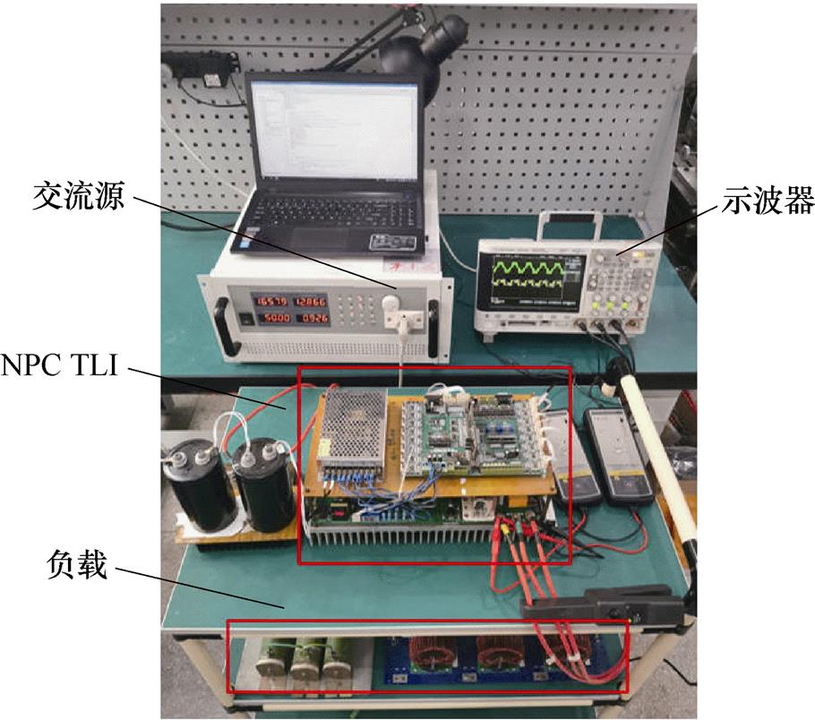
图10 NPC TLI实验平台
Fig.10 Experimental platform of NPC TLI
表4 系统参数
Tab.4 System parameters
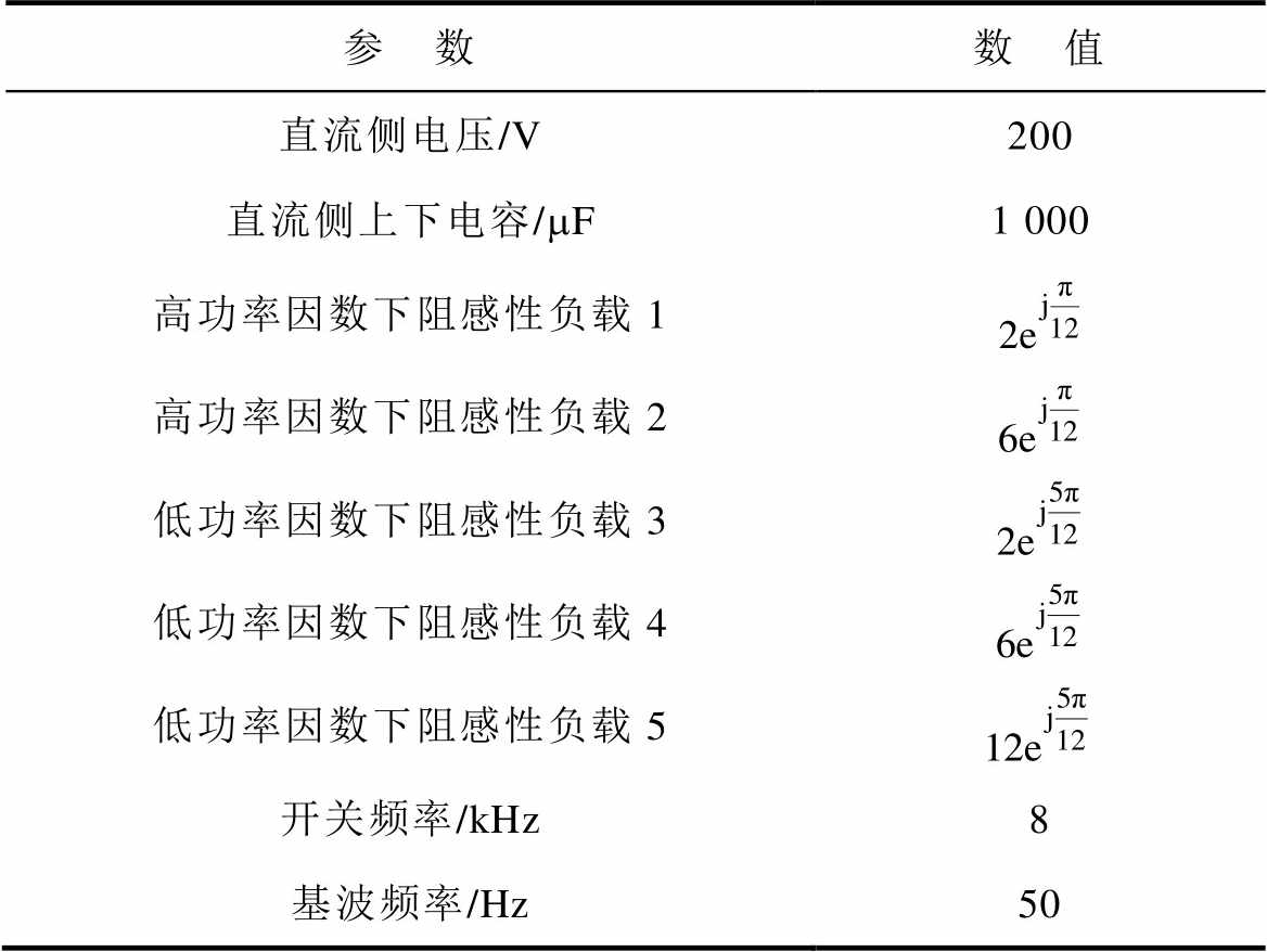
参 数数 值 直流侧电压/V200 直流侧上下电容/mF1 000 高功率因数下阻感性负载1 高功率因数下阻感性负载2 低功率因数下阻感性负载3 低功率因数下阻感性负载4 低功率因数下阻感性负载5 开关频率/kHz8 基波频率/Hz50
图11给出了CBPWM的稳态实验结果。当m= 0.3,j=p/12和j=5p/12时,NPV几乎没有波动;当m=0.9,j=p/12时,NPV的波动也很小,说明在这三种条件下CBPWM能很好地控制NPV;当m=0.9,j=5p/12时,NPV出现明显的三倍频波动。观察图11d中双调制波 和
和 的波形可发现部分区间被钳位,这意味着CBPWM对NPV的控制能力变差。
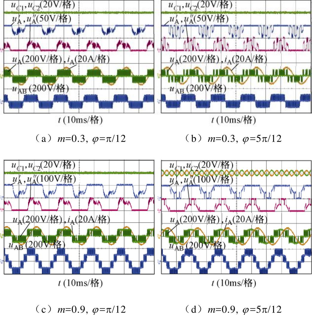
图11 CBPWM的稳态实验结果
Fig.11 Steady state experimental results under CBPWM
图12给出了VSVPWM的稳态实验结果。显然,在全调制度和功率因数范围内,NPV几乎没有波动。同时,因为VSVPWM可以无条件实现NPV平衡,NPV主动控制的影响也很小,双调制波的波形基本不变。
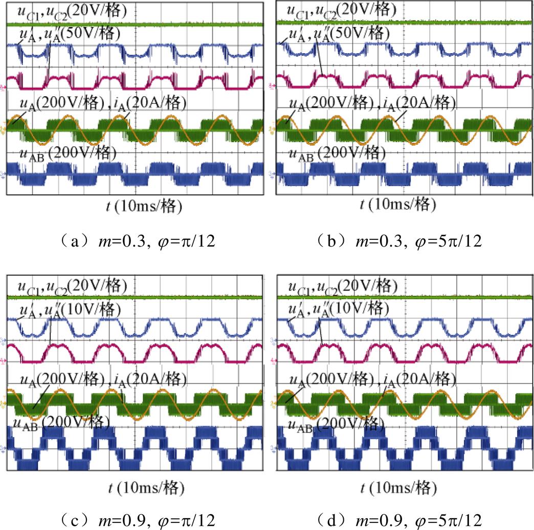
图12 VSVPWM的稳态实验结果
Fig.12 Steady state experimental results under VSVPWM
图13给出了FM_VSVPWM的稳态实验结果。在全功率因数全调制度范围内,NPV几乎没有波动。当j=p/12,m=0.3和0.9时,CBPWM和FM_ VSVPWM的双调制波 、
、 大致相同,说明上述条件下,FM_VSVPWM基本采用CBPWM的两种模式;当j=p/12,m=0.3和0.9时,CBPWM和FM_ VSVPWM的双调制波、存在较大差异,说明在此条件下,FM_VSVPWM采用另外两种模式的时间较多。
为了更直观地展现FM_VSVPWM在降低开关损耗方面的优势,图14给出了稳态实验中CBPWM、VSVPWM以及FM_VSVPWM的开关损耗统计。
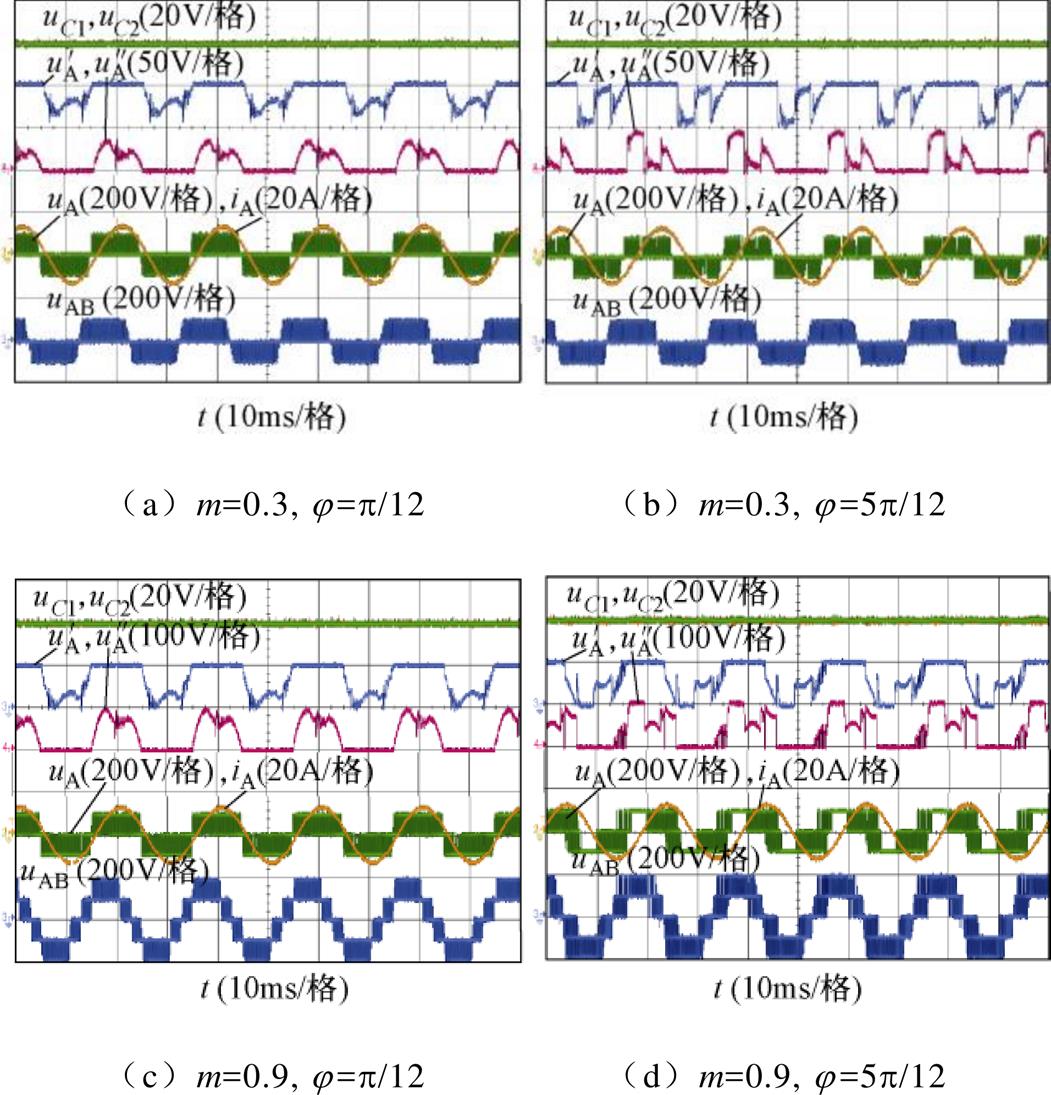
图13 FM_VSVPWM的稳态实验结果
Fig.13 Steady state experimental results under FM_VSVPWM
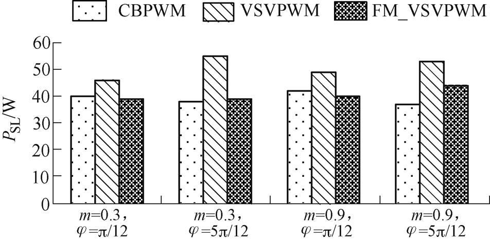
图14 稳态实验中CBPWM、VSVPWM和FM_VSVPWM的开关损耗
Fig.14 Switching losses of CBPWM, VSVPWM and FM_VSVPWM in steady state experiment
图14中,VSVPWM的开关损耗始终比CBPWM的开关损耗大,FM_VSVPWM的开关损耗明显比VSVPWM的开关损耗小。当m=0.3时,FM_ VSVPWM的开关损耗与CBPWM的开关损耗几乎相等;当m=0.9,j=p/12时,FM_VSVPWM的开关损耗略小于CBPWM的开关损耗;当m=0.9,j= 5p/12时,FM_VSVPWM的开关损耗略大于CBPWM的开关损耗。因此,FM_VSVPWM在降低开关损耗方面具有显著优势。
图15、图16给出了CBPWM、VSVPWM和FM_VSVPWM的NPV恢复实验结果,初始时NPV存在20V偏移。可以看出,三种调制策略都能很好地恢复NPV平衡。图15a中,当m=0.9,j=5p/12时,使用CBPWM后NPV出现较大的三倍频波动。
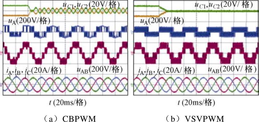
图15 当m=0.9, j=5p/12时,CBPWM和VSVPWM的NPV恢复实验
Fig.15 NPV recovery experiment under CBPWM and VSVPWM when m=0.9 and j=5p/12
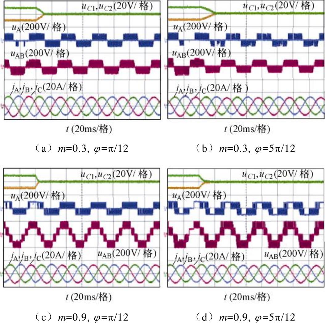
图16 FM_VSVPWM的NPV恢复实验
Fig.16 NPV recovery experiment under FM_VSVPWM
图17给出了FM_VSVPWM的动态实验结果,包括调制度突变和负载突变。可以看出,在突变过程中,NPV始终保持平衡,说明FM_VSVPWM能很好地控制NPV的平衡。
为了和VSVPWM一样能在全调制度和功率因数范围内实现NPV平衡,同时相比VSVPWM可降低开关损耗,本文基于调制波分解提出了FM_ VSVPWM。与VSVPWM类似,所提调制策略在每一个载波周期内均能够使得NPC TLI中点电流平均值为零,从而实现良好的NPV控制,且开关次数与CBPWM一致,相比VSVPWM降低一次。与CBPWM和VSVPWM相比,FM_VSVPWM在实现NPV平衡和降低开关损耗方面具有一定优势。实验结果表明,FM_VSVPWM可以和VSVPWM一样很好地控制NPV,且开关损耗较VSVPWM有明显降低。
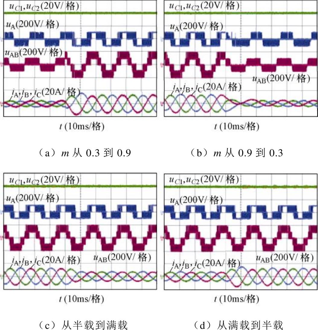
图17 FM_VSVPWM的动态实验结果
Fig.17 Dynamic experimental results under FM_VSVPWM
参考文献
[1] 高瞻, 李耀华, 葛琼璇, 等. 一种三电平中点钳位变流器改进型载波反相层叠脉宽调制策略[J]. 电工技术学报, 2021, 36(4): 831-842.
Gao Zhan, Li Yaohua, Ge Qiongxuan, et al. Improved phase opposition disposition pulse width modulation strategy for three-level neutral point clamped converter[J]. Transactions of China Electrotechnical Society, 2021, 36(4): 831-842.
[2] Wang Rutian, Ai Lan, Liu Chuang. A novel three- phase dual-output neutral-point-clamped three-level inverter[J]. IEEE Transactions on Power Electronics, 2021, 36(7): 7576-7586.
[3] 孟庆云, 晏明, 潘启军, 等. 一种适用于大容量中点钳位型三电平逆变器的绝缘栅双极型晶体管吸收电路研究[J]. 中国电机工程学报, 2016, 36(3): 755-764.
Meng Qingyun, Yan Ming, Pan Qijun, et al. Research on a insulated gate bipolar transistor snubber circuit for the high power neutral point clamped three-level inverter[J]. Proceedings of the CSEE, 2016, 36(3): 755-764.
[4] He Jinkui, Sangwongwanich A, Yang Yongheng, et al. Lifetime evaluation of three-level inverters for 1500V photovoltaic systems[J]. IEEE Journal of Emerging and Selected Topics in Power Electronics, 2021, 9(4): 4285-4298.
[5] 邱继浪, 何英杰, 焦乾明, 等. 非隔离型三电平逆变器漏电流抑制与中点电位平衡控制[J]. 电力系统自动化, 2021, 45(17): 161-170.
Qiu Jilang, He Yingjie, Jiao Qianming, et al. Leakage current suppression and balance control of neutral point potential for three-level transformerless inver- ter[J]. Automation of Electric Power Systems, 2021, 45(17): 161-170.
[6] 罗锐, 何英杰, 陈晖, 等. 三电平变流器中点电位平衡及低开关损耗SVPWM策略[J]. 电工技术学报, 2018, 33(14): 3245-3254.
Luo Rui, He Yingjie, Chen Hui, et al. SVPWM scheme for three-level converters with neutral-point potential balancing and switching loss reduction[J]. Transactions of China Electrotechnical Society, 2018, 33(14): 3245-3254.
[7] 张建忠, 胡路才, 徐帅. 一种零序电压注入的T型三电平逆变器中点电位平衡控制方法[J]. 电工技术学报, 2020, 35(4): 807-816.
Zhang Jianzhong, Hu Lucai, Xu Shuai. Neutral potential balance control method of T-type three-level inverter with zero-sequence voltage injection[J]. Transactions of China Electrotechnical Society, 2020, 35(4): 807-816.
[8] 高瞻, 李耀华, 葛琼璇, 等. 适用于大功率三电平中点钳位整流器的SVPWM和DPWM策略研究[J].电工技术学报, 2020, 35(23): 4864-4876.
Gao Zhan, Li Yaohua, Ge Qiongxuan, et al. Research on SVPWM and DPWM strategies suitable for high power three-level neutral point clamped rectifier[J]. Transactions of China Electrotechnical Society, 2020, 35(23): 4864-4876.
[9] 刘云峰, 何英杰, 程瑞琪, 等. 单相二极管箝位多电平逆变器CBPWM与SVPWM调制策略的等效关系[J]. 电机与控制学报, 2020, 24(9): 13-21.
Liu Yunfeng, He Yingjie, Cheng Ruiqi, et al. Equivalent relationship between carrier-based and space vector PWM strategy in single phase NPC multi-level inverter[J]. Electric Machines and Control, 2020, 24(9): 13-21.
[10] 方辉, 宋文胜, 冯晓云, 等. 三电平SVPWM与CBPWM算法的内在联系研究[J]. 电工技术学报, 2014, 29(10): 19-26.
Fang Hui, Song Wensheng, Feng Xiaoyun, et al. Relationship between three-level SVPWM and CBPWM[J]. Transactions of China Electrotechnical Society, 2014, 29(10): 19-26.
[11] Busquets-Monge S, Bordonau J, Boroyevich D, et al. The nearest three virtual space vector PWM-a modulation for the comprehensive neutral-point balancing in the three-level NPC inverter[J]. IEEE Power Electronics Letters, 2004, 2(1): 11-15.
[12] Wan Wenchao, Duan Shanxu, Chen Changsong, et al. A hybrid control method for neutral-point voltage balancing in three-level inverters[J]. IEEE Transa- ctions on Power Electronics, 2021, 36(8): 8575-8582.
[13] Liu Peng, Duan Shanxu, Yao Chuan, et al. A double modulation wave CBPWM strategy providing neutral- point voltage oscillation elimination and CMV reduction for three-level NPC inverters[J]. IEEE Transactions on Industrial Electronics, 2018, 65(1): 16-26.
[14] Xia Shuai, Wu Xiaojia, Zheng Jinggang, et al. A virtual space vector PWM with active neutral point voltage control and common mode voltage suppression for three-level NPC converters[J]. IEEE Transactions on Industrial Electronics, 2021, 68(12): 11761- 11771.
[15] 李敏裕, 马晓军, 魏曙光, 等. 三电平虚拟空间矢量脉宽调制算法窄脉冲抑制研究[J]. 电工技术学报, 2018, 33(14): 3264-3273.
Li Minyu, Ma Xiaojun, Wei Shuguang, et al. Research on narrow pulse suppression of three-level virtual space vector pulse width modulation algorithm[J]. Transactions of China Electrotechnical Society, 2018, 33(14): 3264-3273.
[16] An S, Lee K. A reliability improvement method for three-level inverters with modified VSVPWM[C]// IEEE PELS Workshop on Emerging Technologies: Wireless Power Transfer (WoW), Seoul, Korea (South), 2020: 184-188.
[17] Jiang Weidong, Wang Peidong, Ma Mingna, et al. A novel virtual space vector modulation with reduced common-mode voltage and eliminated neutral point voltage oscillation for neutral point clamped three- level inverter[J]. IEEE Transactions on Industrial Electronics, 2020, 67(2): 884-894.
[18] Wang Jinping, Gui Zaiyi, Wang Peixia, et al. A carrier-based modulation with planned zero sequence voltage injection to control neutral point voltage for three-level inverter[J]. IEEE Access, 2020, 8: 64799- 64809.
[19] Jiang Weidong, Jiang Haoran, Liu Shengyu, et al. A carrier-based discontinuous PWM strategy for T-type three-level converter with reduced common mode voltage, switching loss, and neutral point voltage control[J]. IEEE Transactions on Power Electronics, 2022, 37(2): 1761-1771.
Abstract Compared with the two-level inverter, the neutral point clamped three-level inverter (NPC TLI) has the advantages of low electromagnetic interference, low voltage stress of switching devices, and low total harmonic distortion (THD). Therefore, it is widely used in renewable energy generation, the transmission of high voltage and high power, medium/high voltage variable frequency motor drives, and so on.
Carrier-based pulse width modulation (CBPWM) method and space vector pulse width modulation (SVPWM) method are usually applied to NPC TLI, which are equivalent to a certain extent. CBPWM generates PWM sequences by comparing double carriers and single modulation waves. In this paper, the carrier of CBPWM is optimized by replacing double carriers with a single carrier. Then, the modulation wave is processed to eliminate the negative value. Accordingly, this paper proposes a modulation wave decomposition method and applies it to virtual space vector pulse width modulation (VSVPWM). The neutral point voltage (NPV) can still be unconditionally balanced under VSVPWM with this method, which proves the feasibility of the method.
Compared with CBPWM, the switching loss is increased when VSVPWM is used, even though NPV can be unconditionally balanced, which greatly affects the power conversion efficiency of the inverter. Six modulation waves can be obtained when VSVPWM with the proposed method of modulation wave decomposition is used, and two of them are clamped. Limiting the modulation wave that is not clamped reduces the switching action of a specific phase and the switching loss. Four modes can be obtained after the modulation waves are limited, so this method is named FM_VSVPWM in this paper. Compared with VSVPWM, when the proposed FM_VSVPWM is used, the switching loss can be effectively reduced, and NPV can also be balanced in the full range of modulation index and power factor.
The steady-state experimental results show that when the modulation index is 0.9, and the power factor is 0.26. NPV fluctuates with triple fundamental frequency, and the fluctuation amplitude is about 6 % of the DC link voltage when CBPWM is used. When VSVPWM and the proposed FM_VSVPWM are used, NPV can always be balanced in the full range of modulation index and power factor. In addition, the switching losses of the above three methods are compared in this paper. Compared with VSVPWM, when FM_VSVPWM is used, the switching losses are reduced by 13 %, which proves the superiority of the proposed FM_VSVPWM in reducing switching loss. The NPV recovery experimental result shows that even if there is a 10 % offset on the DC link capacitor voltage, NPV can still recover quickly. The dynamic experimental results include the sudden change of modulation index and the sudden change of load. The results show that when FM_VSVPWM is used, NPV can keep balance when external interference is added. Moreover, the current THD of the three methods is compared. The results show that when the modulation index is low, compared with VSVPWM, the current THD of FM_VSVPWM decreases from 11.8 % to 8.5 %.
keywords:Neutral point clamped three-level inverter, modulation wave decomposition, balanced neutral point voltage, switching loss, modulation strategy
DOI: 10.19595/j.cnki.1000-6753.tces.220897
中图分类号:TM464
国家自然科学基金面上资助项目(52077050)。
收稿日期 2022-05-23
改稿日期 2022-07-13
王金平 男,1984年生,博士,副研究员,硕士生导师,研究方向为开关变换器拓扑及其控制。E-mail: waupter919@163.com(通信作者)
刘 斌 男,1998年生,硕士研究生,研究方向为电力电子与电力传动。E-mail: 2021110321@mail.hfut.edu.cn
(编辑 陈 诚)