 。本文从模型参数误差以及逆变器非线性的角度,总结了影响无位置传感器稳态运行时TFPMM位置偏差的因素。为消除位置估算偏差,通过对观测器所用电感参数施加扰动,根据稳态工况下的机械方程,构建非线性方程组,利用列文伯格-马夸特法(Levenberg-Marquardt algorithm)求解方程,并将结果应用到观测器中,实现无位置传感器运行时电感和永磁体磁链的辨识及估算位置稳态偏差的修正。最后基于一台三相聚磁式双边无源转子横向磁通永磁电机,对所提算法进行仿真与实验验证。
摘要 三相横向磁通永磁电机采用无位置传感器控制时,和永磁同步电机类似,位置偏差主要受到模型参数误差以及逆变器非线性等因素影响。该文依据估计直轴电流为0时的位置偏差方程,提出一种稳态工况下注入电感扰动的参数辨识方法以修正位置误差。该方法通过对观测器所用电感值施加扰动,构建非线性方程组,采用列文伯格-马夸特法求解,实现电感及永磁体磁链的准确辨识,并将辨识结果应用到观测器中,从而改善了无位置传感器运行的位置精度。仿真与实验结果验证了该方法的可行性与有效性。
关键词:横向磁通永磁同步电机 电感扰动 列文伯格-马夸特法 位置偏差 参数辨识
近年来,横向磁通永磁电机(Transverse Flux Permanent Magnet Machine, TFPMM)由于磁场在空间呈三维分布,相间解耦且采用形式简单且绕制方便的环形绕组,使得其空间利用率高、输出转矩大,广泛适用于电动汽车及其他电力直驱场合[1],同时可借鉴已经成熟的永磁同步电机的控制方法。
永磁同步电机的无位置传感器技术可以省略机械式传感器或作为有位置传感器时的冗余设计,降低成本,同时提高系统可靠性[2-7]。在中高速范围内,基于基波反电动势观测器的方法如滑模观测器(Sliding Mode Observer, SMO)、扩展卡尔曼滤波器(Extended Kalman Filter, EKF)等广泛应用于位置估计中[8]。其中,滑模观测器由于其鲁棒性强及结构简单等优点,在工业中广泛适用[9]。
然而,由于电机运行过程中电阻、电感和磁链参数受温度、磁饱和、负载扰动的影响而发生改 变[10]、逆变器非线性等非理想因素导致指令电压与实际电压之间存在误差[11]等,观测器估算位置与实际位置之间存在偏差。文献[12]通过参数敏感性分析,得出模型不确定性对于位置估算的影响。文献[13]提出一种基于最小电流追踪的位置偏差校正算法,该方法适用于稳态工况且无需对各类误差建模即可补偿总位置偏差,然而由于固定跟踪步长难以选取,需多次实验得到。文献[14]提出基于高斯-牛顿迭代法的表贴式永磁同步电机多参数在线辨识策略,通过向估计d轴注入电流以满足参数辨识满秩条件,最终提高了估算位置精度,但复杂的矩阵计算不可避免地会加重控制系统的计算负担。文献[15]结合滑模补偿器设计了一种改进的磁链观测器,通过滑模补偿器消除估算位置偏差,但滑模补偿器观测位置误差的精度受模型参数精度影响。文献[16]依据李雅普诺夫稳定性理论提出一种电阻自适应的滑模观测器,克服了电机运行过程中电阻参数变化的影响,但是需要已知精确的电感参数。文献[17]为拓展永磁电机基波模型的辨识自由度,从5、7次谐波反电动势中提取位置信息,提出基于谐波模型的定子电阻与转子磁链自适应的无位置传感器算法,然而谐波反电动势提取位置算法复杂且逆变器非线性需准确补偿。
受带宽限制,中高速无位置传感器控制常应用在负载较平缓的稳态工况,即负载转矩满足 。本文从模型参数误差以及逆变器非线性的角度,总结了影响无位置传感器稳态运行时TFPMM位置偏差的因素。为消除位置估算偏差,通过对观测器所用电感参数施加扰动,根据稳态工况下的机械方程,构建非线性方程组,利用列文伯格-马夸特法(Levenberg-Marquardt algorithm)求解方程,并将结果应用到观测器中,实现无位置传感器运行时电感和永磁体磁链的辨识及估算位置稳态偏差的修正。最后基于一台三相聚磁式双边无源转子横向磁通永磁电机,对所提算法进行仿真与实验验证。
本文研究的三相TFPMM为聚磁式双边无源转子结构,其爆炸视图如图1所示。定子由工型定子铁心和工型永磁体沿圆周方向交替排列组成,永磁体周向磁化,相邻永磁体充磁方向相反,每相定子只包含一个跑道型电枢绕组。转子结构轴向布置在定子结构两侧,每个转子铁心均包括沿径向排布的两圈转子齿。
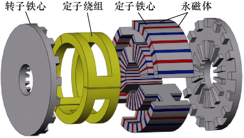
图1 三相TFPMM结构
Fig.1 Structure of three-phase TFPMM
图2为空载时三相自感La、Lb和Lc及互感Lab的有限元仿真结果,自感最大值为5.417 7 mH,最小值为5.207 5 mH,平均值为5.320 7 mH,电机凸极性较弱。互感平均值为-0.11 mH,为自感的2 %,相比普通永磁同步电机可忽略相间互感,实现了相间解耦。
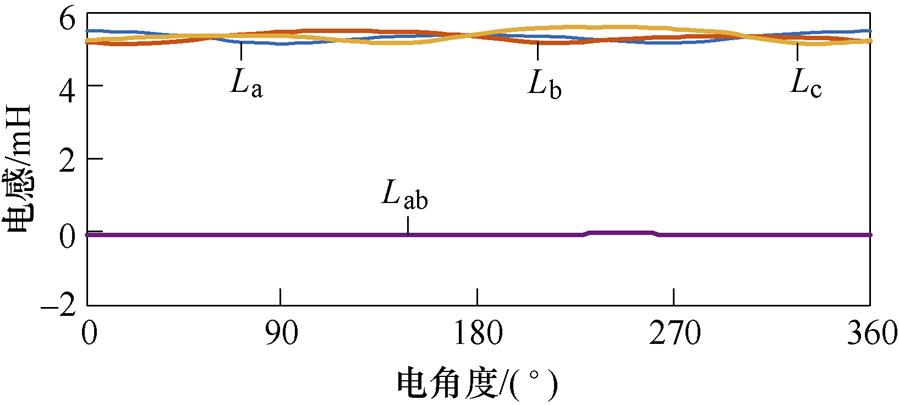
图2 三相自感及互感空载仿真结果
Fig.2 Simulation results of three-phase self inductance and mutual inductance under no load
由上文可知,三相TFPMM模型与表贴式永磁同步电机类似,其在ab 坐标系下的数学模型为
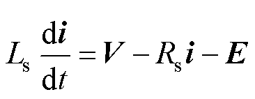 (1)
(1)
式中,V为实际电压矢量,V=[uaub]T;i为电流矢量,i=[iaib]T;E为反电动势矢量,E=[eaeb]T;Rs与Ls分别为ab 坐标系下TFPMM的相电阻及相电感。
构建滑模观测器为
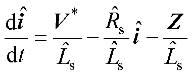 (2)
(2)
式中, 为估计电流矢量,
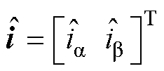 ;
; 为由电流误差构成的等效控制项,
 ,k为滑模观测器增益,
 为Sigmoid函数;
 为参考电压矢量,
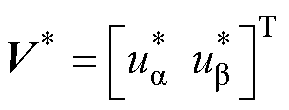 ;
; 与
与 分别为滑模观测器采用的相电阻及相电感估计值。
若k值选择合适,滑模观测器收敛。根据等效控制理论,此时反电动势估计值 。当
。当
 且
且 时,反电动势实际值等于估计值,即
 。为从反电动势中提取位置信息,采用锁相环(Phase Locked Loop, PLL)结构。位置与转速估算系统的结构框图如图3所示,图中
 和
和 分别为估算电角度与估算电角速度。

图3 位置与转速估算系统结构框图
Fig.3 Block diagram of the position and speed estimation system
TFPMM估算位置稳态偏差主要受到模型参数误差及逆变器非线性影响,下面分别对这两方面进行分析。
1.2.1 模型参数误差
TFPMM无位置传感器稳态运行时,模型参数误差导致的估计反电动势误差矢量 可写为
可写为
 (3)
(3)
式中, 为电阻参数误差,
 ;
; 为电感参数误差,
 。
。
1.2.2 逆变器非线性
忽略开关管与二极管导通压降差异时,逆变器非线性产生的三相误差电压[18]为
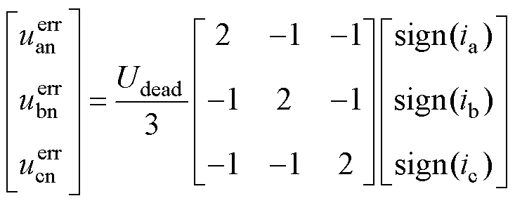 (4)
(4)
式中, 、
、 和
和 为三相误差电压;Udead为死区误差电压幅值,受死区时间、开通/关断延迟等影响;ia、ib和ic为a、b、c三相电流。
将式(4)左乘Clarke矩阵变换到ab 坐标系并通过傅里叶分解得到误差电压基波分量为
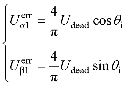 (5)
(5)
式中, 为电流矢量电角度;
 和
和 分别为误差电压基波矢量在a 轴与b 轴的分量。逆变器非线性产生的误差电压基波矢量
 可由式(5)各分量合成得
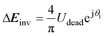 (6)
(6)
由式(6)可知, 与电流矢量
与电流矢量 同相位。综上所述,估算反电动势基波矢量
 为
为
 (7)
(7)
结合式(3)~式(7)可绘制稳态估算位置偏差空间矢量如图4所示,图中dq为电机同步旋转坐标系,dg 为估算位置旋转坐标系。电流矢量 在d 轴和g 轴的分量分别为id 和ig。
由于采用锁相环从反电动势频率中提取位置信息,因此 幅值误差不影响估计位置精度。由图4a可知,采用
 控制时
控制时 相位偏差受到电阻、电感及逆变器非线性共同影响;而由图4b可知,当采用
 控制时,
控制时, 相位偏差仅受电感偏差影响,因此为避免多参数影响无位置传感器控制策略,采用
 控制,此时估算位置偏差
 为
为
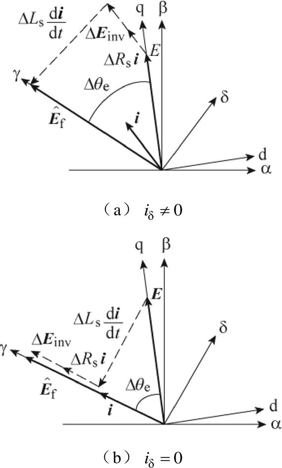
图4 估算位置偏差空间矢量
Fig.4 Space vector diagram of estimated position deviation
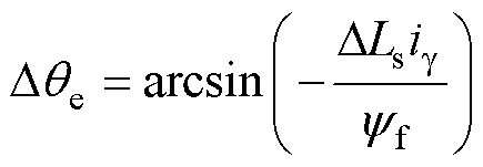 (8)
(8)
式中, ;yf为永磁体磁链。
采用幅值不变约束时三相TFPMM转矩方程为
 (9)
(9)
式中,ig1为未注入电感扰动时g 轴电流;np为极对数。将式(8)代入式(9)中得到
 (10)
(10)
对观测器所用电感参数注入正向扰动+Dd,此时稳态转矩方程为
 (11)
(11)
式中,ig2为注入电感扰动+Dd时g 轴电流。
对观测器所用电感参数注入负向扰动-Dd,此时稳态转矩方程为
 (12)
(12)
式中,ig3为注入电感扰动-Dd时g 轴电流。
平稳工况下注入前后负载转矩不变,结合式(10)~式(12),可得非线性方程组为
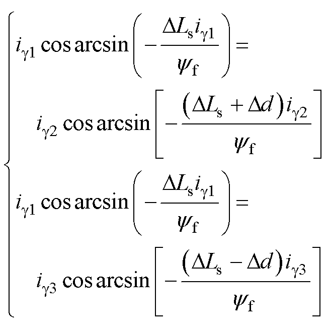 (13)
(13)
求解该二维非线性方程组,即可得到电感误差DLs及永磁体磁链yf。图5为单次电感扰动注入与电流采集过程,注入前后延迟一段时间,保证电机达到稳态后再采集电流平均值。
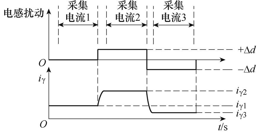
图5 单次电感扰动注入与电流采集过程
Fig.5 Process of single inductance perturbationinjection and current acquisition
列文伯格-马夸特法是基于高斯-牛顿法基础上的一种改进非线性最小二乘方法,其核心思想是通过引入正则项l,改善非线性最小二乘矩阵为病态矩阵时方程解不收敛的情况[19]。
列文伯格-马夸特法主要包括两个步骤:一是求解增量方程;二是调整正则项l。其增量方程为
 (14)
(14)
式中,Dx为当前迭代步长;J(x)为雅可比矩阵;I为单位矩阵;l 为正则项;g(x)=JT(x)f (x),f (x)为当前函数值。
正则项l 通过判断总体误差F(x)增减进行调节。若总体误差变大,令l=2l;否则令l=0.5l。
本文采用列文伯格-马夸特法求解式(13)。将式(13)改写成式(15)的形式,即
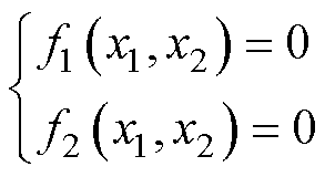 (15)
(15)
式中,x1为DLs;x2为yf。其雅可比矩阵J(x)为
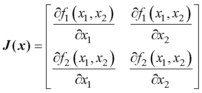 (16)
(16)
列文伯格-马夸特法执行流程如图6所示。
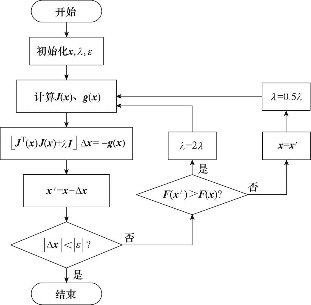
图6 列文伯格-马夸特法流程
Fig.6 Flow chart of Levenberg-Marquardt algorithm
为验证本文提出算法的有效性,本文基于一台三相聚磁式双边无源转子横向磁通永磁电机样机进行仿真研究,电机主要参数见表1。表中,相电阻、相电感及永磁体磁链均为常温且磁路未饱和时离线测得。
表1 TFPMM参数
Tab.1 TFPMM parameters

参 数数 值 极对数np16 相电阻Rs/W0.615 相电感Ls/mH3.7 永磁体磁链yf/Wb0.011 54 额定转速n/(r/min)300 额定电流I/A8
基于电感扰动的参数辨识及位置偏差修正系统框图如图7所示。
仿真中转速为300 r/min,负载转矩为2 N·m。图8为DRs=0.2 W,DLs=0.4 mH时的电感扰动注入过程的仿真结果。分别在0.5 s和1.5 s注入+Dd和-Dd的电感扰动(Dd选取为0.2 mH),并在g 轴电流到达稳态后在T1、T2及T3时间段内提取其平均值。图9为列文伯格-马夸特法求解的迭代过程,最后电感偏差辨识值收敛到0.451 mH,即电感辨识值为3.751 mH,误差为1.38 %;永磁体磁链辨识值为0.012 Wb,误差为3.98 %。以上辨识结果表明,本文所提方法可在电机电阻参数存在误差时,较准确地辨识电感和永磁体磁链。
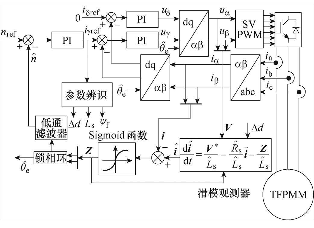
图7 基于电感扰动的参数辨识及位置偏差修正系统框图
Fig.7 Block diagram of parameter identification and position deviation correction based on inductance perturbation injection
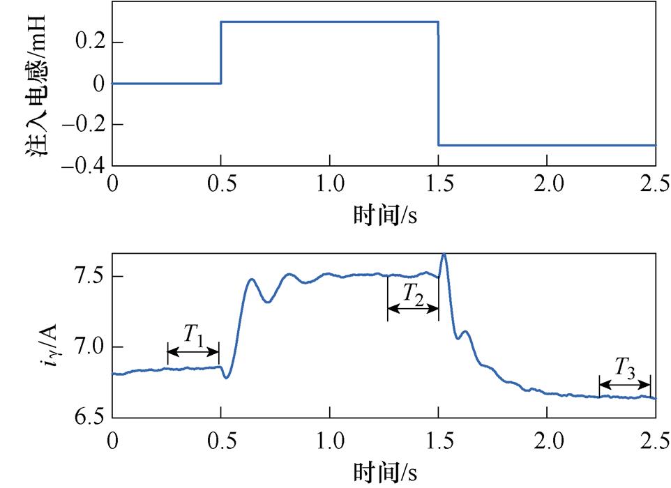
图8 电感扰动注入过程仿真结果
Fig.8 Simulation results of inductance perturbation injection process
本文采用TMS320F28335作为主控芯片,搭建如图10所示的三相聚磁式双边无源转子横向磁通永磁电机实验平台,对所提方法进行实验验证。其中实验电机参数同表1,位置与速度信息由2 048线增量式光电编码器测量。采集电流通过串口通信传递给上位机运行参数辨识程序,最后再将辨识参数应用到滑模观测器中。实验中开关频率为10 kHz,死区时间设置为3 ms。实验波形经DAC输出,由于算法目的为修正位置直流偏差,因此g 轴电流与位置偏差均经滤波处理以证明实验效果。
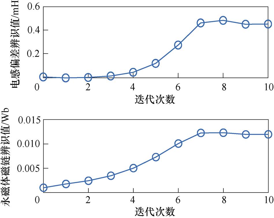
图9 参数辨识结果
Fig.9 Parameter identification results
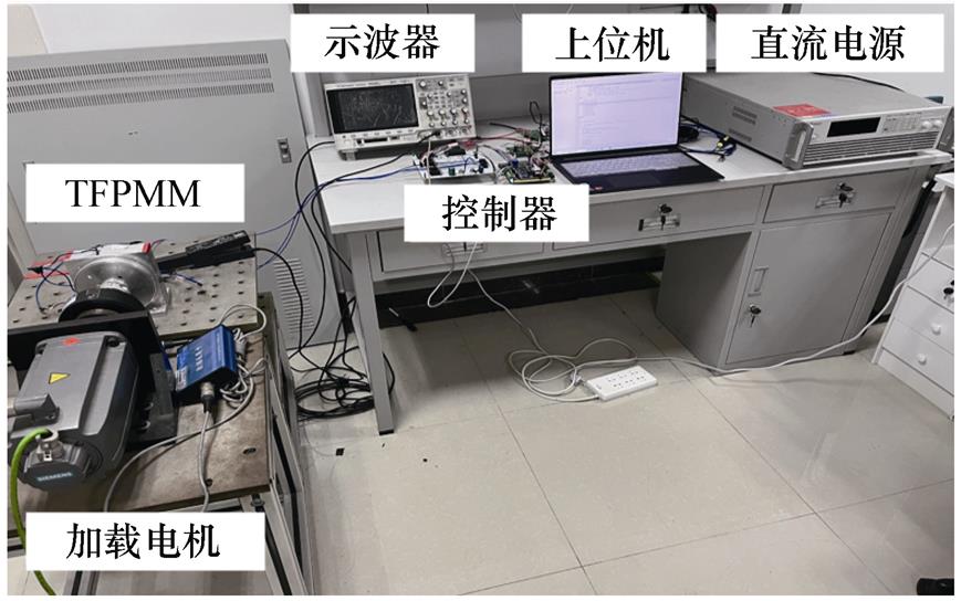
图10 三相TFPMM实验平台
Fig.10 Experiment platform of three phase TFPMM
为避免电流采样、电磁干扰等不确定因素造成的误差,实际工况注入4次不同的电感扰动,取4次辨识参数平均值作为最终辨识值。图11为电感扰动注入算法流程。首先初始化阈值h =0.02 A(该值受电流采样精度、噪声等影响,可通过提前实验获得),Dd=0.05 mH,然后通过扰动确定Dd最小值,避免Dd过大或过小导致的电机参数偏移和信噪比过小时参数不收敛问题,最后注入4次不同扰动并求辨识参数平均值。当DLs=0时,ig2=ig3,式(13)解不唯一,因此为保证方程解的收敛性,注入扰动后添加判断条件|ig2-ig3|>h,若满足,则记录电流值;反之,改变负向扰动为原来的2倍重新注入。
300 r/min空载运行时,设定DRs=0.2 W,DLs= 0.7 mH,此时由电感参数引起的位置误差为-12.3 °。首先通过扰动可确定Dd最小值为0.2 mH,随后每间隔1 s注入1次电感扰动,在电流达到稳态后采样电流平均值。图12为相应实验结果,Ⅰ、Ⅱ、Ⅲ、Ⅳ对应电感扰动值分别为0.2 mH、0.4 mH、0.6 mH和0.8 mH。
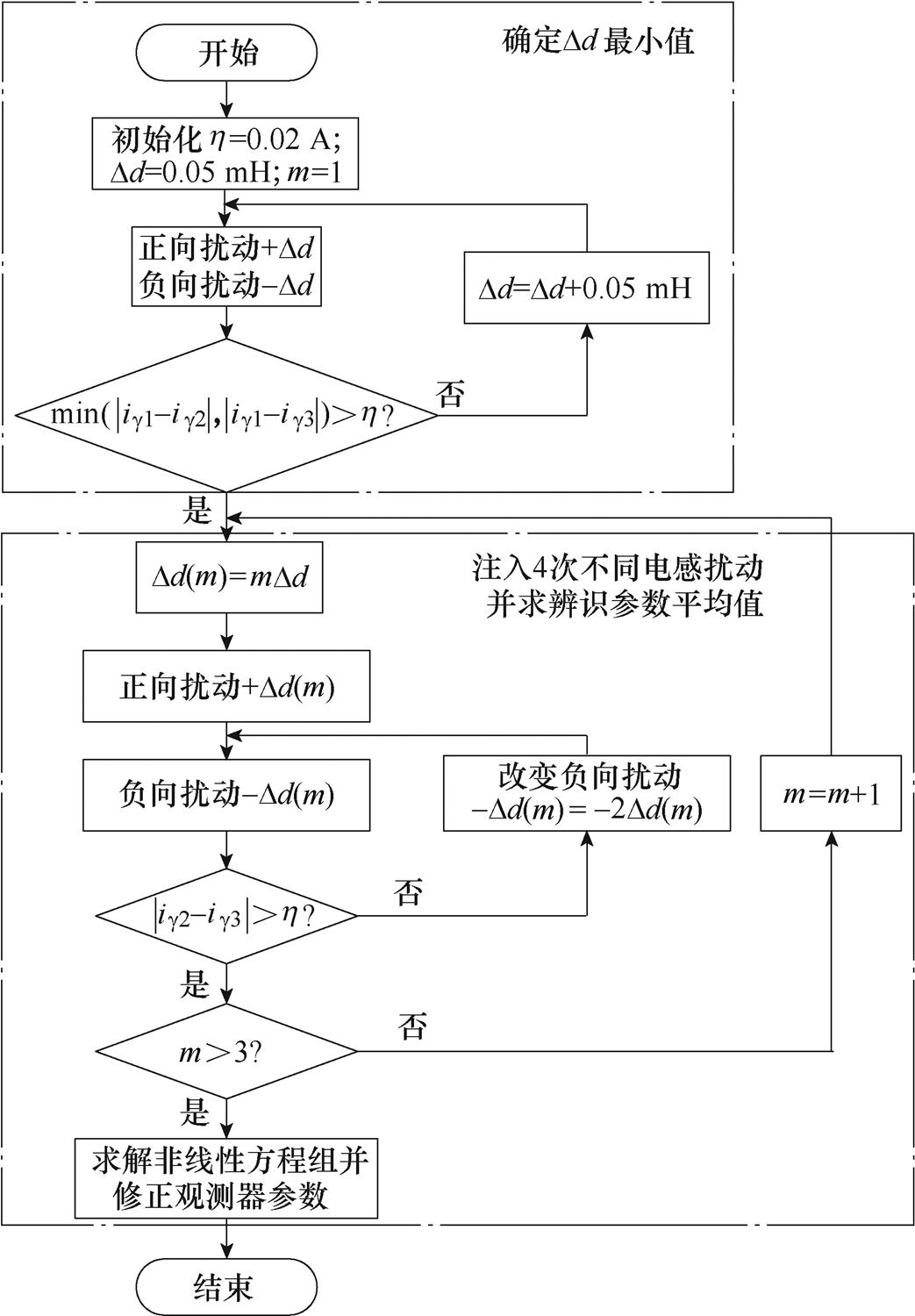
图11 电感扰动注入算法流程
Fig.11 Flow chart of inductance perturbation algorithm
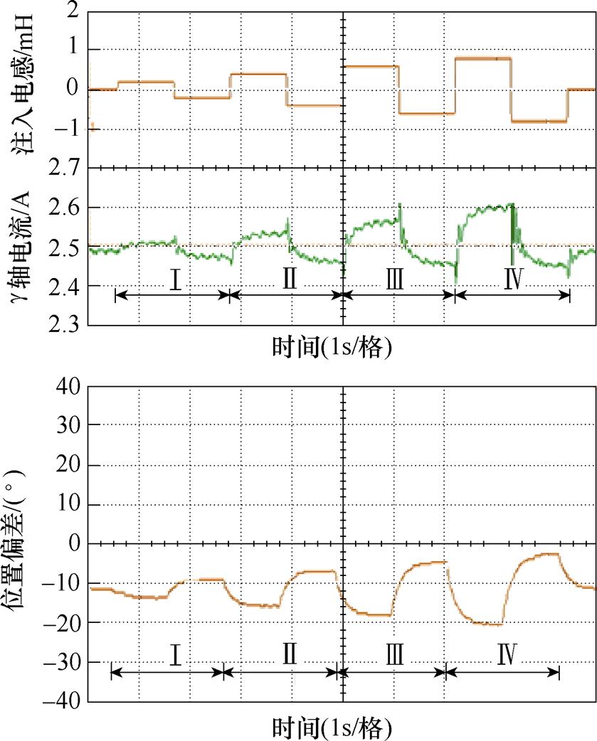
图12 空载实验结果
Fig.12 Experimental results under no load
空载不同Dd辨识结果见表2,参数辨识迭代过程如图13所示。辨识算法在迭代15次后收敛,取4次辨识结果的平均值,得电感辨识值为3.687 1 mH,误差为3.49 %;永磁体磁链辨识值为0.012 3 Wb,误差为6.58 %。
表2 空载不同Dd参数辨识结果
Tab.2 Parameter identification results at different Dd under no load

Dd/mH电感辨识值/mH永磁体磁链辨识值/Wb 0.23.60410.0111 0.43.73530.0127 0.63.67430.0126 0.83.73470.0127
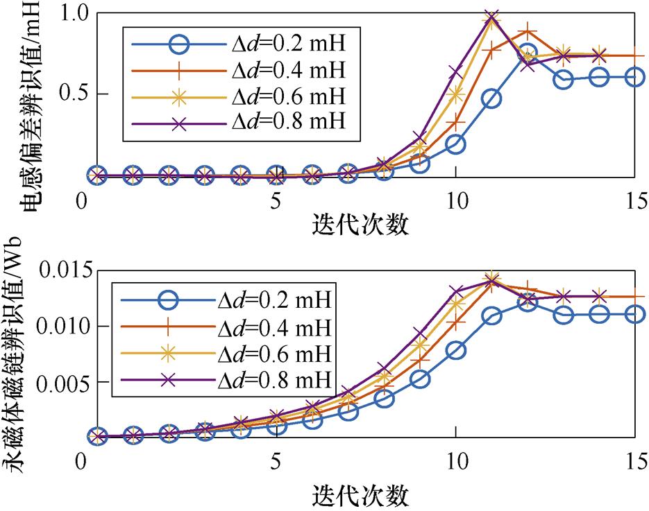
图13 参数辨识迭代过程
Fig.13 Iterative process of parameter identification
最后将辨识电感参数应用到滑模观测器中,图14为空载辨识前后位置偏差实验结果,位置偏差角由辨识前的-12.3 °减小到-1.98 °。
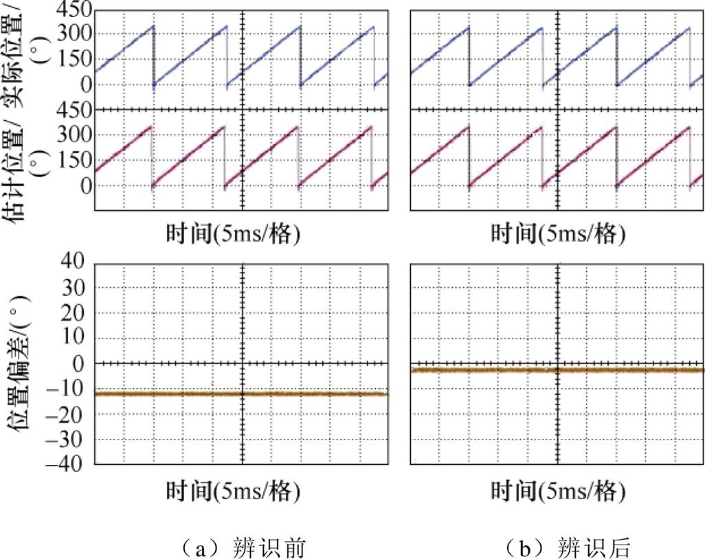
图14 空载辨识前后位置偏差实验结果
Fig.14 Experimental results of position deviation before and after identification under no load
300 r/min负载转矩2 N·m运行时,设定DRs= 0.2 W,DLs=0.7 mH,此时由电感参数引起的位置误差为-17.6 °。首先通过扰动可确定Dd最小值为0.05 mH,随后每间隔1 s注入1次电感扰动。图15为相应实验结果,Ⅰ、Ⅱ、Ⅲ、Ⅳ对应电感扰动值分别为0.05 mH、0.1 mH、0.15 mH和0.2 mH。
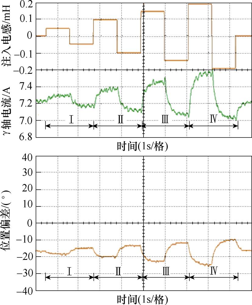
图15 负载条件下实验结果
Fig.15 Experimental results under load condition
负载条件下不同Dd辨识结果见表3,参数辨识迭代过程分别如图16所示。辨识算法在迭代15次后收敛,取4次辨识结果的平均值,得电感辨识值为3.459 9 mH,误差为6.49 %;永磁体磁链辨识值为0.012 8 Wb,误差为10.05 %。
表3 负载条件下不同Dd参数辨识结果
Tab.3 Parameter identification results at different Dd under load condition

Dd/mH电感辨识值/mH永磁体磁链辨识值/Wb 0.053.34590.0112 0.13.41000.0122 0.153.65840.0152 0.23.42530.0125
最后将辨识电感参数应用到滑模观测器中,图17为负载条件下辨识前后位置偏差实验结果,位置偏差角度由辨识前的-17.6 °减小到-2.32 °。
为验证所提方法在不同转速、不同负载下的有效性,表4和表5分别给出了不同工况下电感辨识实验结果和永磁体磁链辨识实验结果。表6为使用所辨识电感参数修正滑模观测器后,不同工况下的位置偏差。

图16 负载条件下参数辨识迭代过程
Fig.16 Iterative process of parameter identification under load condition

图17 实验结果
Fig.17 Experimental results
表4 不同工况电感辨识结果
Tab.4 Identification results of inductance at different operation states

负载/(N·m)电感辨识/mH 260r/min280r/min300r/min 空载3.64133.62903.6871 13.80413.52063.6067 1.53.31613.42583.6001 23.54753.43523.4599
由表6可以看出,所提算法在不同工况下电角度偏差均控制在2.86 °以内,考虑到预定位精度与增量式编码器分辨率限制,基本修正无位置传感器控制时的位置偏差,但负载条件下辨识误差增大,为进一步分析辨识误差来源,采用有效磁链模型[20],其表达式为
表5 不同工况永磁体磁链辨识结果
Tab.5 Identification results of rotor flux linkage at different operation states

负载/(N·m)磁链辨识/Wb 260r/min280r/min300r/min 空载0.01140.01160.0123 10.01240.01170.0118 1.50.01070.01220.0116 20.01300.01050.0127
表6 不同工况修正后位置偏差角度
Tab.6 Position deviation after correction at different operation states

负载/(N·m)角度/(°) 260r/min280r/min300r/min 空载-1.68-1.84-1.98 12.12-2.21-2.1 1.5-2.84-0.711.75 20.13-2.86-2.32
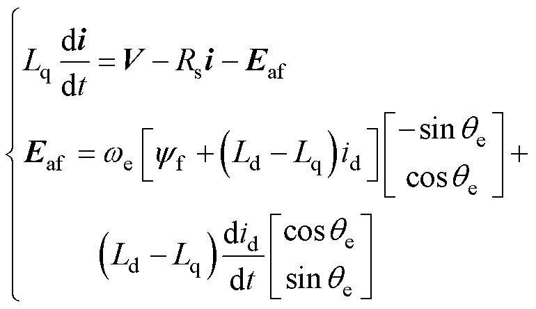 (17)
(17)
式中,Ld和Lq分别为电机d轴与q轴电感; 为有效磁链对应反电动势;we为电机电角速度;id和iq分别为电机d、q轴电流。稳态时由
 可得
可得
 (18)
(18)
图18为考虑凸极性且采用 控制时稳态估算位置偏差空间矢量。此时估算位置偏差为
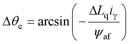 (19)
(19)
其中


式中, 为滑模观测器使用的电感参数。
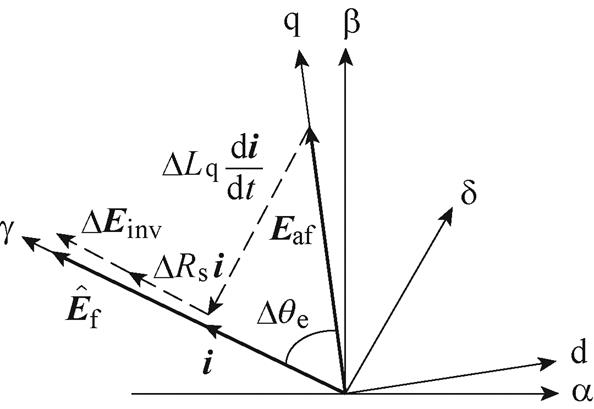
图18 考虑凸极性时估算位置偏差空间矢量( )
)
Fig.18 Space vector diagram of estimated position deviation considering saliency ( )
)
实验中Dd选取为较小值,因此扰动前后id和iq变化很小,Ld和Lq近似不变,此时辨识方程为
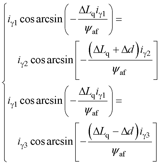 (20)
(20)
由式(20)可知,实际辨识电感为Lq,因此负载条件下由于磁路饱和,辨识电感相比表1中离线测量电感Ls偏小;实际辨识永磁体磁链为yaf,存在由于磁路饱和产生的磁链误差(Ld-Lq)id。由于观测器中并未使用永磁体磁链,且由式(19)可知,在辨识Lq后修正观测器参数,即可修正位置偏差。
针对无位置传感器控制时的位置偏差问题,本文提出一种基于电感扰动的位置偏差修正方法,对观测器电感参数注入扰动构建辨识模型,运用列文伯格-马夸特法求解辨识方程,最后修正滑模观测器中电感参数值从而修正位置偏差,仿真与实验验证了所提方法在空载和负载工况下的有效性与鲁棒性。相比于其他方法,本文方法具有以下优点:
1)不依赖模型的精确参数且不受逆变器非线性影响,仅需永磁体磁链的先验范围以保证滑模观测器收敛。
2)求解矩阵维数低,计算简单,易于实现。
3)能够比较精确地求解所辨识参数,有效抑制估算位置稳态误差。
但该方法仅适用于凸极性较弱的永磁同步电机,存在一定局限性。如何将其应用到凸极性强的永磁同步电机中,是接下来的研究重点。
参考文献
[1] Chen Jiaxin, Chen Zhihui, Duan Jinjin, et al. Four- phase transverse flux permanent magnet motor control system with AC current control based on PR regu- lator[C]//2019 22nd International Conference on Electrical Machines and Systems (ICEMS), Harbin, China, 2019: 1-6.
[2] 王彤. 永磁电机无位置传感器控制及在线参数辨识研究[D]. 杭州: 浙江大学, 2019.
[3] 刘计龙, 肖飞, 沈洋, 等. 永磁同步电机无位置传感器控制技术研究综述[J]. 电工技术学报, 2017, 32(16): 76-88.
Liu Jilong, Xiao Fei, Shen Yang, et al. Position- sensorless control technology of permanent-magnet synchronous motor-a review[J]. Transactions of China Electrotechnical Society, 2017, 32(16): 76-88.
[4] 章春娟, 王慧贞, 刘伟峰, 等. 基于宽频带同步基频提取滤波器的永磁同步电机转子位置与转速估计[J]. 电工技术学报, 2022, 37(4): 882-891.
Zhang Chunjuan, Wang Huizhen, Liu Weifeng, et al. Rotor position and speed estimation of permanent magnet synchronous motor based on wideband syn- chronous fundamental frequency extraction filter[J]. Transactions of China Electrotechnical Society, 2022, 37(4): 882-891.
[5] 赵文祥, 刘桓, 陶涛, 等. 基于虚拟信号和高频脉振信号注入的无位置传感器内置式永磁同步电机MTPA控制[J]. 电工技术学报, 2021, 36(24): 5092- 5100.
Zhao Wengxiang, Liu Huan, Tao Tao, et al. MTPA control of sensorless IPMSM based on virtual signal and high-frequency pulsating signal injection[J]. Transactions of China Electrotechnical Society, 2021, 36(24): 5092-5100.
[6] 麦志勤, 刘计龙, 肖飞, 等. 基于估计位置反馈电流解调算法的改进型高频旋转电压注入无位置传感器控制策略[J]. 电工技术学报, 2022, 37(4): 870-881, 891.
Mai Zhiqin, Liu Jilong, Xiao Fei, et al. Sensorless control strategy of improved HF rotating voltage injection based on estimated position feedback current demodulation algorithm[J]. Transactions of China Electrotechnical Society, 2022, 37(4): 870-881, 891.
[7] 阙鸿杰, 全力, 张丽, 等. 基于自适应滤波器在线解耦的磁场增强型永磁电机无位置传感器控制[J]. 电工技术学报, 2022, 37(2): 344-354.
Que Hongjie, Quan Li, Zhang Li, et al. Sensorless control of flux-intensifying permanent magnet syn- chronous motor based on adaptive Notch filter online decoupling[J]. Transactions of China Electrotechnical Society, 2022, 37(2): 344-354.
[8] Liu Gang, Zhang Haifeng, Song Xinda. Position- estimation deviation-suppression technology of PMSM combining phase self-compensation SMO and feed- forward PLL[J]. IEEE Journal of Emerging and Selected Topics in Power Electronics, 2021, 9(1): 335-344.
[9] Liang Donglai, Li Jian, Qu Ronghai, et al. Adaptive second-order sliding-mode observer for PMSM sensor- less control considering VSI nonlinearity[J]. IEEE Transactions on Power Electronics, 2018, 33(10): 8994-9004.
[10] 刘细平, 胡卫平, 丁卫中, 等. 永磁同步电机多参数辨识方法研究[J]. 电工技术学报, 2020, 35(6): 1198-1207.
Liu Xiping, Hu Weiping, Ding Weizhong, et al. Research on multi-parameter identification method of permanent magnet synchronous motor[J]. Transa- ctions of China Electrotechnical Society, 2020, 35(6): 1198-1207.
[11] 史婷娜, 刘华, 陈炜, 等. 考虑逆变器非线性因素的表贴式永磁同步电机参数辨识[J]. 电工技术学报, 2017, 32(7): 77-83.
Shi Tingna, Liu Hua, Chen Wei, et al. Parameter identification of surface permanent magnet syn- chronous machines considering voltage-source inverter nonlinearity[J]. Transactions of China Electrotech- nical Society, 2017, 32(7): 77-83.
[12] Bolognani S, Ortombina L, Tinazzi F, et al. Model sensitivity of fundamental-frequency-based position estimators for sensorless PM and reluctance syn- chronous motor drives[J]. IEEE Transactions on Industrial Electronics, 2018, 65(1): 77-85.
[13] Gu Cong, Wang Xiaolin, Zhang Feilong, et al. Correction of rotor position estimation error for high- speed permanent magnet synchronous motor sensor- less drive system based on minimum-current-tracking method[J]. IEEE Transactions on Industrial Electro- nics, 2020, 67(10): 8271-8280.
[14] Wang Yangrui, Xu Yongxiang, Zou Jibin. Online multiparameter identification method for sensorless control of SPMSM[J]. IEEE Transactions on Power Electronics, 2020, 35(10): 10601-10613.
[15] Tang Qipeng, Chen Duxin, He Xiangning. Integration of improved flux linkage observer and I-f starting method for wide-speed-range sensorless SPMSM drives[J]. IEEE Transactions on Power Electronics, 2020, 35(8): 8374-8383.
[16] Kim H, Son J, Lee J. A high-speed sliding-mode observer for the sensorless speed control of a PMSM[J]. IEEE Transactions on Industrial Electro- nics, 2011, 58(9): 4069-4077.
[17] Wang Tong, Huang Jin, Ye Ming, et al. An EMF observer for PMSM sensorless drives adaptive to stator resistance and rotor flux linkage[J]. IEEE Journal of Emerging and Selected Topics in Power Electronics, 2019, 7(3): 1899-1913.
[18] Kim H W, Youn M J, Cho K Y, et al. Nonlinearity estimation and compensation of PWM VSI for PMSM under resistance and flux linkage uncertainty[J]. IEEE Transactions on Control Systems Technology, 2006, 14(4): 589-601.
[19] Burden R L, Faires J D, Burden A M. Numerical analysis[M]. Boston: Cengage Learning, 2015.
[20] Boldea I, Paicu M C, Andreescu G D. Active flux concept for motion-sensorless unified AC drives[J]. IEEE Transactions on Power Electronics, 2008, 23(5): 2612-2618.
Abstract Transverse flux permanent magnet machines (TFPMM) have been widely used in electric vehicles and other direct-drive applications due to the high output torque. The sensorless control of TFPMM can omit mechanical sensors, reduce cost and improve system reliability. However, the stator resistance, inductance, and flux linkage change from temperature, magnetic saturation, and load disturbance during the operation of the motor, and the nonlinearity of the inverter produce errors between the command voltage and the actual voltage, thus causing deviations between the estimated position and the actual position. This paper proposes a parameter identification method based on inductance perturbations independent of the accuracy of any parameters to correct the position deviation.
Firstly, the two main factors that cause position deviation are analyzed under steady state, model parameter error, and inverter nonlinearity. It can be intuitively obtained that the position deviation is only affected by the inductance parameter error in the sliding mode observer as soon as  . Secondly, according to the torque equation of TFPMM, the inductance perturbations of +Dd and -Dd are injected separately, and average values of g-axis current are extracted after the g-axis current reaches a steady state. Based on the assumption that the load torque changes slowly, the nonlinear equations of inductance error and the permanent magnet flux linkage are constructed. The Levenberg-Marquardt algorithm, which improves the non-convergence of the solution when the Jacobian matrix is ill-conditioned, is used to solve the nonlinear equations. The identification of inductance and permanent magnet flux linkage is realized. Finally, the identified inductance is fed back to the observer to correct position deviation.
Specific operating conditions are simulated and investigated based on a prototype of TFPMM to verify the effectiveness of the proposed method. The inductance and the permanent magnet flux linkage can be obtained by the Levenberg-Marquardt algorithm with errors of 1.38 % and 3.98 %, respectively. Further experiments are carried out to verify the feasibility and robustness of the method. By analyzing the results under different speeds and loads, it can be concluded that the mechanical angle deviation of the proposed method is controlled within 0.178 ° under different operating conditions. However, the identification error increases significantly under load conditions. Thus, the position deviation equation considering the saturation effect is deduced using the active flux concept. In the case of near-zero saliency, the identified inductance and flux linkage are Lq and yaf, respectively. However, the permanent magnet flux linkage is not used in the observer. The position deviation equation considering the saturation effect shows that the position deviation can be corrected by modifying the observer parameters after identifying Lq.
The following conclusions can be drawn from the simulation and experimental results: (1) The proposed method does not require accurate model parameters and is unaffected by the inverter nonlinearity. Only a priori range of permanent magnet flux linkage is required to ensure convergence of the sliding mode observer. (2) The matrix dimension is low, and the calculation is simple and easy to implement. (3) The identified parameters can be solved accurately, and the steady-state position error can be suppressed effectively. The proposed method is also suitable for permanent magnet synchronous machines (PMSM) with near-zero saliency. Improvement of position estimation for salient PMSM will be the next focus of our research.
keywords:Transverse flux permanent magnet machine, inductance perturbation, Levenberg-Marquardt algorithm, position deviation, parameter identification
DOI: 10.19595/j.cnki.1000-6753.tces.220642
中图分类号:TM351
国家自然科学基金资助项目(51677090)。
收稿日期2022-04-23
改稿日期 2022-07-27
苏有成 男,1998年生,硕士研究生,研究方向为横向磁通永磁电机控制。E-mail: nuaasyc@nuaa.edu.cn
陈志辉 男,1972年生,教授,博士生导师,研究方向为特种电机及其数字控制技术、航空电源、风力发电控制技术。E-mail: chenzhh@nuaa.edu.cn(通信作者)
(编辑 崔文静)