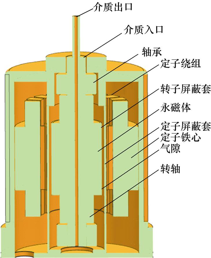
图1 电机结构
Fig.1 Motor rotor structure
摘要 基于3D流体场模型和有限元体积法,针对高速永磁屏蔽电机进行转子表面介质摩擦损耗计算和敏感性因素分析,研究转子转速、介质轴向流速、屏蔽套表面粗糙度对气隙内介质摩擦损耗的影响规律。基于一台额定转速36 000 r/min的电机结构,对半径比为0.896~0.930的窄气隙泰勒-库埃特-泊肃叶(TCP)流进行仿真分析,得到摩擦阻力系数与水轴向流速、转子转速的关系,并采用非线性拟合的方法得出不同轴向流速和转子转速的摩擦损耗系数经验公式。随后,搭建试验平台测量摩擦损耗,对比试验测得与仿真求得的摩擦损耗大小以及数值仿真与经验公式计算的摩擦损耗系数,误差在5 %范围内,满足工程要求,验证了数值仿真分析和经验公式的准确性。
关键词:高速永磁屏蔽电机 水摩擦损耗 摩擦系数经验公式 TCP流
高速永磁屏蔽电机(High-Speed Permanent Magnet Synchronous Motor, HSPMSM)作为屏蔽泵的驱动电机,适用于各种特殊液体介质的输送,液体介质可作为冷却剂进行冷却;定转子表面分别装有圆筒状的屏蔽套,使定子绕组、永磁体免受输送介质的腐蚀,因此其具有体积小、噪声低、耐腐蚀、转速高、功率密度大、安全可靠等优点[1-4]。电机采用气隙介质循环的冷却方式,广泛应用于航空航天、水下、石油化工、小型核动力反应堆等领域[5]。
气隙内介质随转子转动产生摩擦损耗,文献[6]指出,气隙摩擦损耗可按照电机额定功率的1 %~5 %进行估算,而对于高速永磁屏蔽电机来说,转子表面转速高达几万转甚至几十万转,由此产生的摩擦损耗比普通电机大得多,占总损耗比例很大,且与转子散热条件密切相关,按照经验值选取已不再适用。同时,高速永磁屏蔽电机体积小,散热困难,过高的温升容易引成永磁体不可逆退磁和零部件老化等问题[7],因此,准确计算气隙介质摩擦损耗可以为合理设计电机的转子结构和冷却方式提供依据,对电机的长期安全可靠运行具有重要意义。目前,国内外学者对气隙流体产生的摩擦损耗研究通常是从流动本身出发,探究流体流速与阻力特性的关系,使用数值模拟计算流体摩擦损耗大小。母玉[8]以20 MW变频调速电机为例,详细分析了计算流体力学(Computational Fluid Dynamics, CFD)几种湍流模型的优缺点,从流体粘性力出发,通过在CFD- POST后处理中输入表达式的方法计算剪切应力来计算摩擦损耗。陈鹏等[9]使用牛顿粘性公式、获取转子壁面力矩和耦合能量方程这三种方法对电机内部呈层流状态的空气摩擦损耗进行了计算,结果表明这三种方法得到的数值误差很小,近乎一致,但对湍流状态未进行分析。A. B. Nachouane[10]等研究了气隙内部风摩损耗与转子尺寸、气隙宽度、转速和转子表面粗糙度的变化关系,分析了气隙内空气随着电机转速的不断增大从层流到完全湍流的变化过程,并结合仿真数据用最小二乘法的方法提出了计算封闭(没有轴向气流)气隙摩擦损耗系数的分段公式。Wang Shengde[11]等结合Y. Yamada[12]的层流经验公式重点研究了流体流速与轴、切向雷诺数的关系,通过搭建试验平台测量压力和水流量,结合仿真,给出了大半径比的摩擦损耗系数的经验方程。由此可见,用流体场理论对摩擦损耗系数的研究尚处于起步阶段,现今对高转速电机气隙冷却系统的介质摩擦损耗问题进行研究的文献资料还比较少。
本文基于三维流体场物理模型,以一台额定转速36 000 r/min的高速永磁屏蔽电机为例,分析屏蔽套表面粗糙度、转子转速、气隙入口介质流速对电机摩擦损耗的影响。由于水的导热系数和比热容较大、散热能力较好、化学性能稳定、价格低廉、易获得,故以水作为冷却介质进行研究。对不同入口水流流速和转子转速的摩擦损耗系数进行分析,得出了不同半径比、水流流速和转子转速的摩擦损耗系数经验公式。搭建试验平台,将仿真结果与试验结果进行对比分析,验证仿真方法和摩擦损耗系数公式的准确性。
高速永磁同步电机定、转子表面装有屏蔽套,屏蔽套间隙充满冷却介质,电机结构如图1所示。

图1 电机结构
Fig.1 Motor rotor structure
转子额定运行时带动气隙内的介质转动,电机基本尺寸参数见表1。
表1 电机尺寸参数
Tab.1 Motor dimension parameter (单位: mm)
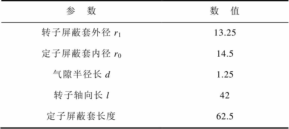
参 数数 值 转子屏蔽套外径r113.25 定子屏蔽套内径r014.5 气隙半径长d1.25 转子轴向长l42 定子屏蔽套长度62.5
根据上述半径和角速度计算,此时转子屏蔽套表面线速度达50 m/s,介质的流动状态可由旋转雷诺数判断,旋转雷诺数是反映粘性力与惯性力作用强弱的物理量,当雷诺数小于2 300时,流体流动状态为层流,粘性力占主导;当雷诺数大于2 300时,流体流动状态为湍流,惯性力占主导。旋转雷诺数计算公式为
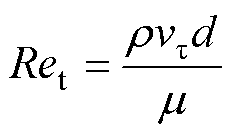 (1)
(1)
式中, 为介质密度(kg/m3);
 为转子屏蔽套表面介质切向流速(m/s);
 为气隙半径(m);
 为介质的动力粘度(Pa·s)。
水的密度是1 000 kg/m3,动力粘度是0.897 3× 10⁻³ Pa·s。经以上分析计算,转子额定转速运行、气隙介质为水时,流动水处于湍流状态。
基于粘性流体力学,利用Fluent流体仿真软件对额定转速工况下气隙水摩擦损耗进行计算。HSPMSM气隙内水的流动满足连续性、动量和能量方程。间隙内水的流动状态为湍流,水的粘性力远远小于惯性力的作用,水的马赫数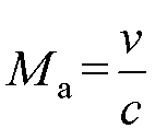 (
( 为音速,一个大气压下为340 m/s,v为水的流速),经计算小于0.3,为不可压缩牛顿流体,选用重整化群的
 湍流模型[13]对旋转流进行计算。
设定电机在室温(25 ℃)下运行,冷却介质为水,对于1.25 mm的小间隙来说,在对数分布律成立的范围内,第一个节点高度小,边界层区域很小,可直接对边界层加密剖分,采用标准壁面函数,用有限元体积法解析计算。
在进行流体场仿真前,做出以下假设:
(1)电机入口没有轴向水流流速,只考虑电机转子旋转带动气隙水流转动,设定气隙流道入口为速度入口,速度设为0,出口为压力出口。
(2)仿真试验在标准大气压、室温下进行。
(3)水摩擦损耗产生的热量转化为内能和势能,由于电机气隙很小,仅1.25 mm,故其势能很小,因此摩擦损耗全部转化为内能排出。转子屏蔽套和定子屏蔽套设为绝热壁面,摩擦产生的热量从入口和出口流出。
(4)指定转子屏蔽套表面为旋转面,设置转子旋转速度为36 000 r/min,定转子屏蔽套表面粗糙度为0。
(5)流体密度保持不变。
经计算,电机额定转速下的摩擦损耗为439 W。
电机运行时,定子屏蔽套和机壳、转子屏蔽套组成的封闭结构将定子铁心、永磁体和冷却水分隔开,阻止流体介质浸入定子槽,保护定子绕组和永磁体,额定转速下电机流体场分布如图2所示,靠近转子区域,水流流速大约为49.9 m/s,与计算值相差0.1 %,由转子套向两边流速逐渐降低,离转子越远,水流流速越低。
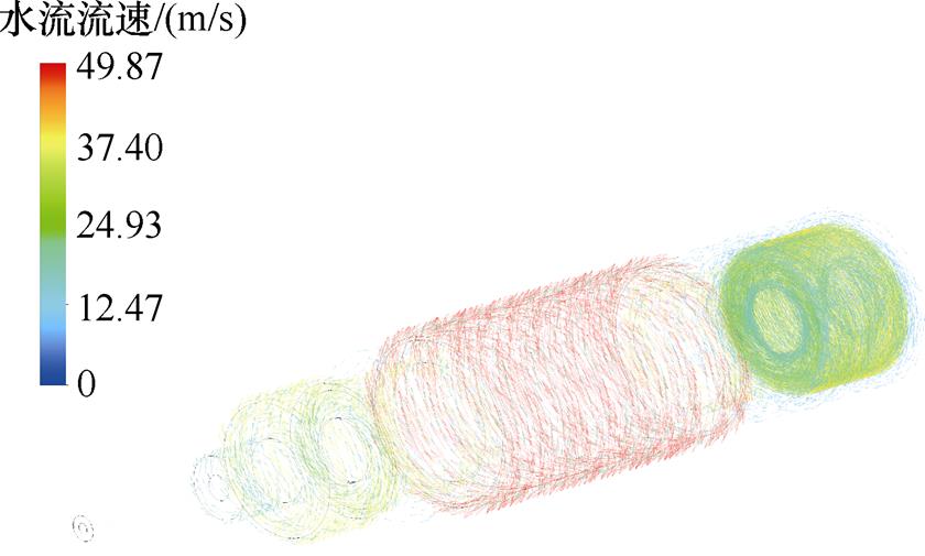
图2 流体场分布
Fig.2 Flow field distribution
通过改变转子转速得到了不同转速工况下的水摩擦损耗,如图3所示。
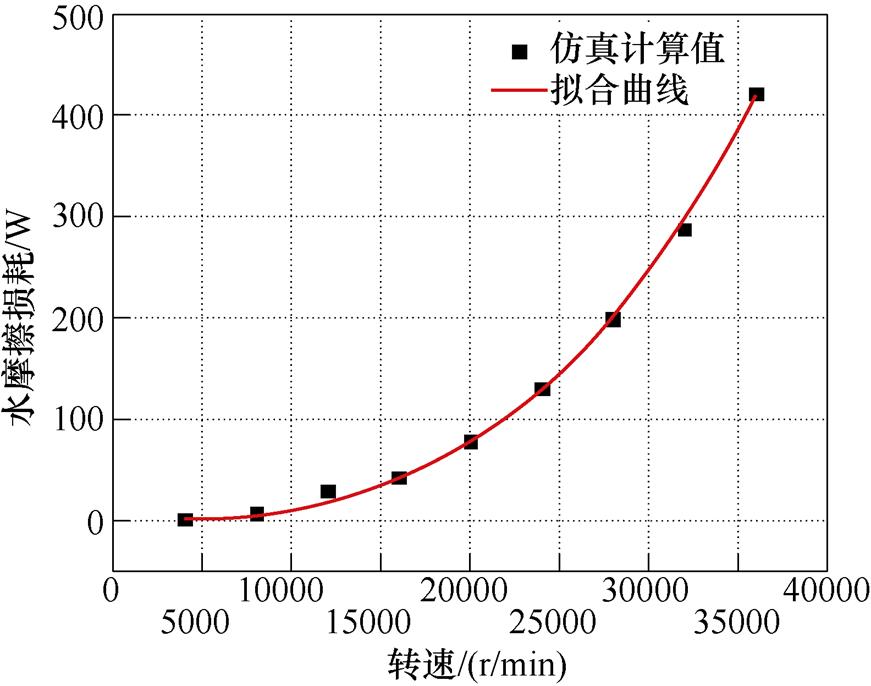
图3 不同转速下的水摩擦损耗
Fig.3 Water friction at different speeds
由图3可以看出,转速 和水摩擦损耗
 的关系近似呈指数变化,随着转子转速增加,旋转雷诺数不断增大,水摩擦损耗也相应增加。对图3数据进行非线性拟合,可得
 (2)
(2)
经计算得,系数 =3.194 33×10-11;幂指数
 = 2.878 25。
电机额定运行,分别改变定转子屏蔽套表面粗糙度,得到水摩擦损耗变化曲线如图4所示。由图4可得,定转子屏蔽套表面粗糙度增加,水摩擦损耗增加。当定子套表面粗糙度由0.05 mm增加到0.075 mm时,损耗值由498 W上升到520 W,增加了4.4 %,当转子套表面粗糙度由0.05 mm增加到0.075 mm时,损耗值由711 W增加到771 W,增长了8.4 %,约为定子套表面粗糙度同等变化的两倍,这是因为转子表面流体速度大,水分子运动剧烈,碰撞产生的热量比靠近定子侧的多,故定转子屏蔽套表面粗糙度改变相同大小,转子侧表面表面粗糙度对水摩擦损耗造成的影响更大。
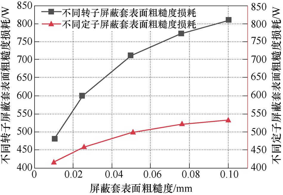
图4 不同屏蔽套表面粗糙度的水摩擦损耗
Fig.4 Water friction of different shielding sleeve roughness
电机转速为36 000 r/min,入口水流流速V分别为0 m/s和5 m/s时的气隙内流体的速度云图和流线图状态如图5所示。
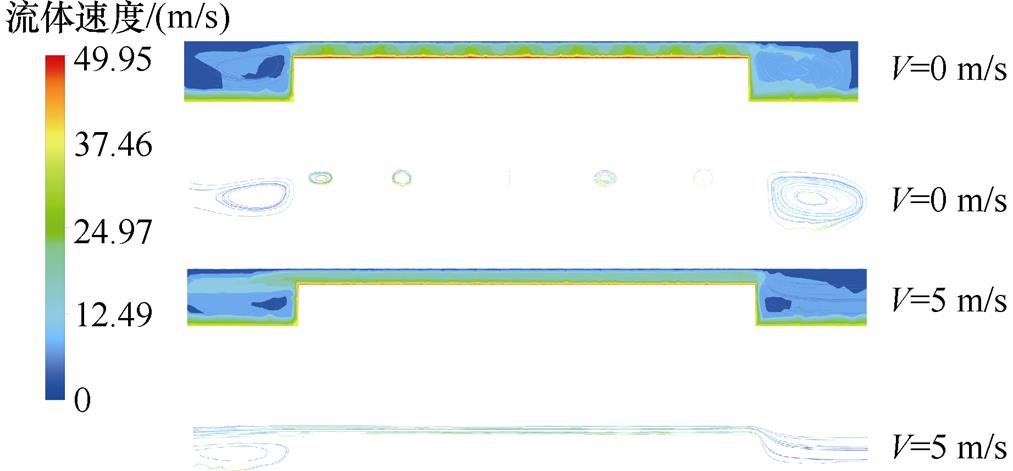
图5 气隙内不同轴向流速的流体状态
Fig.5 Fluid state of different axial velocity in air gap
轴向流速为0时,气隙内流体只受离心力的作用,水在随转子转动过程中流体流态发生了变化,出现了形态均匀的泰勒涡,即稳定的湍流状态。当轴向流速为5 m/s时,水流质点的受力径向大于轴向,均匀的泰勒涡被轴向流冲散,仅有靠近壁面的水流受影响较小,仍保持漩涡的状态。
电机额定运行时,不同轴向水流流速产生的水摩擦损耗如图6所示,轴向流速对水摩擦损耗影响较大,二者近似呈线性变化。
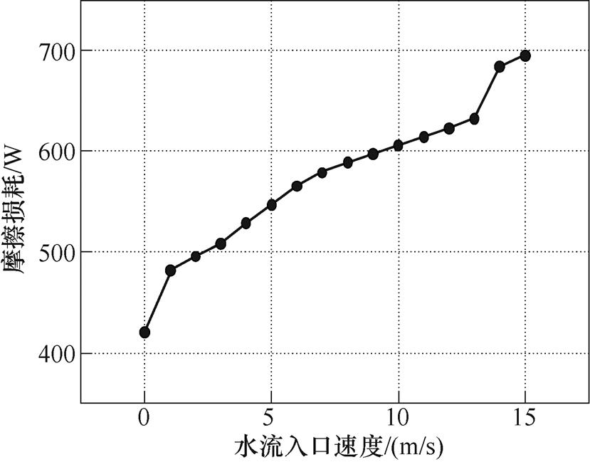
图6 不同入口轴向流速的水摩擦损耗
Fig.6 Water friction at different inlet axial velocities
电机屏蔽套表面产生的摩擦损耗可用经验式(3)计算[14-17]。
 (3)
(3)
式中, 为转子屏蔽套表面粗糙度系数,其取值与转子屏蔽套表面的粗糙程度有关,光滑转子表面,
 =1;轴向开槽表面,
 =2.5[14];Fluent默认0.5,在这里取
 =0.5[15-17]。
 为摩擦系数;
 为转子旋转角速度(rad/s);
 为转子屏蔽套半径(m);
 为转子轴向长度(m)。
对于已知参数的特定转子气隙结构, 是唯一的待解量,在粘性流体力学中
 定义为壁面剪切应力与流体动能之比[18],有
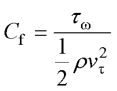 (4)
(4)
其中
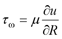 (5)
(5)
式中, 为转子屏蔽套壁面剪切应力(N/m2);
 为水的流速(m/s);
 为转子半径(m)。
显然,在转子转动过程中, 是不断变化的,由于本文电机在额定转速运行时为湍流状态,流体流动受粘性力和惯性力的共同影响,运动状态比较复杂,无法用式(4)计算。
轴向水流流速的改变不仅会影响电机冷却降温的效果,而且轴向水流会带来额外的能量损失,造成气隙水摩擦损耗增加。轴向流速造成的水流状态可由轴向雷诺数Rea判断,有
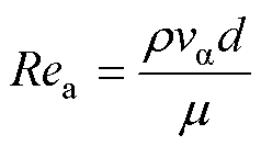 (6)
(6)
式中, 为水的轴向流速。
TCP流是针对同心圆柱体的流体状态进行分析研究的理论系统[19],基于本文电机,将定转子长度统一为转子套长度,TCP流计算域示意图如图7 所示。
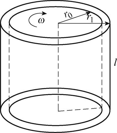
图7 TCP流计算域示意图
Fig.7 Schematic diagram of TCP flow computing domain
运用TCP流,探究水在小气隙中的流动状态及摩擦损耗系数。考虑到屏蔽套厚度对涡流损耗的影响[20-21],选取合适的屏蔽套半径,建立了以下四种TCP参数模型研究旋转流和轴向流的耦合作用对摩擦阻力系数的影响,不同半径比的TCP参数模型见表2。半径比 定义为
定义为 与
与 之比。
之比。
表2 不同半径比的TCP参数模型
Tab.2 TCP parameter models with different radius ratios
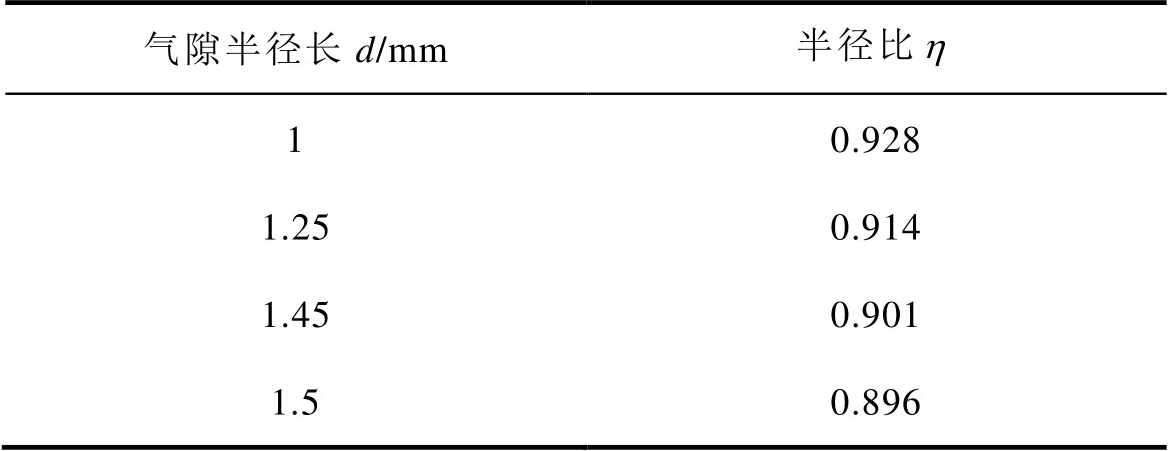
气隙半径长d/mm半径比 10.928 1.250.914 1.450.901 1.50.896
Fluent仿真设置如1.2节所示,忽略电机轴承段,只计算电机气隙段的水摩擦损耗值。
由上述设置建模仿真,电机额定转速运行,改变半径比和轴向水流入口速度,得到不同半径比和轴向雷诺数与摩擦系数的关系曲线,如图8所示。
由图8可知,在轴向流量固定、转子屏蔽套外径不变时,随着半径比的增加,摩擦阻力系数减小,也就是说,随着定子屏蔽套内径减小,气隙宽度减小,摩擦阻力系数减小,因此,对于半径比为0.896~0.930的湍流流动,半径比对摩擦系数的影响不可忽略。此外,摩擦阻力系数随轴向雷诺数的增加而增大,输运理论[22]认为轴向流不变时,旋转雷诺数增加了湍流强度,使间隙中心区域速度变化梯度增大,同样地,旋转雷诺数不变,随着轴向流速度增加,摩擦系数也增加,并且两者呈现指数关系。
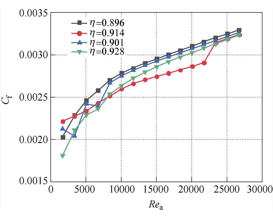
图8 不同半径比和轴向雷诺数与摩擦系数的关系曲线
Fig.8 Relationship curves between friction coefficient and axial Reynolds number with different radius ratios
半径比为0.914时,改变轴向雷诺数和旋转雷诺数,得到了不同雷诺数与摩擦系数的关系曲线,如图9所示。
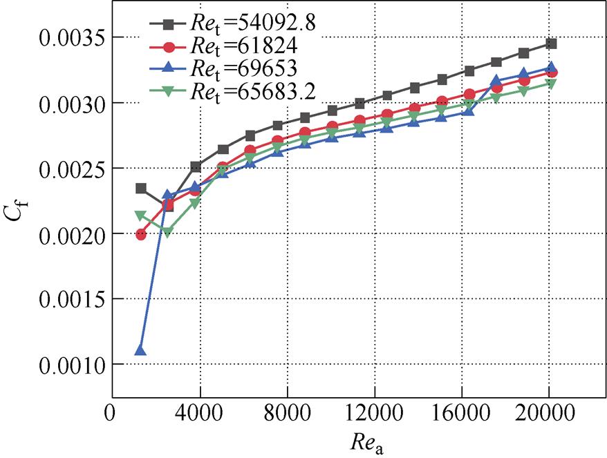
图9 不同轴向雷诺数和旋转雷诺数对摩擦系数的影响曲线
Fig.9 Influence curves of different axial and tangential Reynolds numbers on friction coefficient
由图9可见,轴向雷诺数在4 000~16 000的大致范围内,旋转雷诺数增大,摩擦损耗系数减小,电机额定运行气隙入口水流流速大于3 m/s且保持不变时,电机转速提高,摩擦损耗系数减小,摩擦损耗增大。当旋转雷诺数不变时,随轴向雷诺数增大,摩擦损耗系数增大。
从图8、图9可知,摩擦系数随雷诺数的增大近似呈指数关系变化,在寻找二者之间关系的过程中发现,将两者取对数会得到呈线性变化的规律,故定义摩擦阻力系数表达式为
 (7)
(7)
采用最小二乘法经计算可得
 (8)
(8)
为验证上述公式,新建模型,设置转子外径为26.5 mm,定子外径为28.5 mm,轴长为42 mm,半径比为0.929,设置水流入口速度为5 m/s,转子转速为36 000 r/min。将各参数代入上述公式,得摩擦损耗为486 W,在Fluent中仿真计算结果为480 W,误差为1.3 %,仿真值与计算值近乎一致。
试验原理框图如图10所示,试验时拖动电机侧连接电源供电,利用控制器进行控制,通过联轴器将试验样机与拖动电机连接,实现拖动电机带动试验样机旋转运动;通过测量上游端的电压和电流,便可得到电源侧的输入功率。试验样机采用工装转子,不带磁钢,故没有定子铁耗。试验时拖动电机的效率已知,可求得折算到输出侧的功率大小,忽略联轴器的传动损耗和轴承摩擦损耗,此时求得的功率可近似等于试验样机的摩擦损耗大小。其中,拖动电机的效率经过测功机校核,其数据准确可靠。
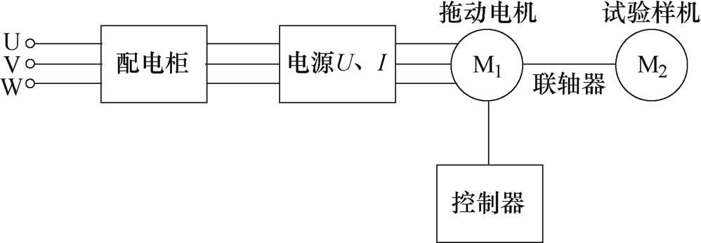
图10 试验原理框图
Fig.10 Test principle block diagram
试验平台有样机和拖动电机两部分,如图11所示,试验样机右边是进水口,左边是出水口,该试验介质从右边圆圈管路通入,左侧圆圈管路排出,无轴孔回流,介质在气隙内流动。
设定样机额定转速为36 000 r/min。转子直径为25 mm、轴长为37 mm时测得摩擦损耗为450 W;转子直径为31 mm、轴长为80 mm时测得摩擦损耗为3.7 kW。
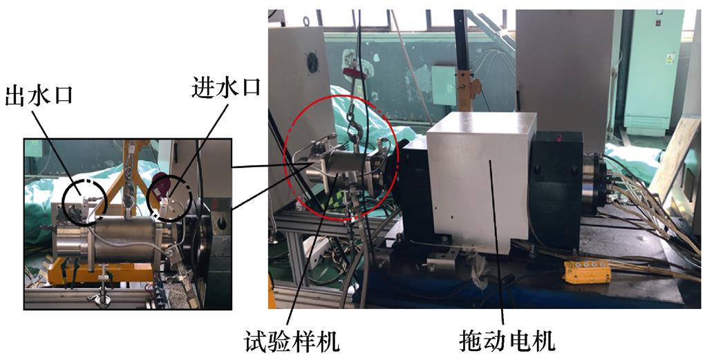
图11 对拖试验平台
Fig.11 Tow test platform
将电机不同直径下水摩擦损耗流体仿真结果和试验测量结果进行比较,见表3。仿真值略小于试验值,可能与轴承摩擦损耗等其他附加损耗计算在内有关,但误差在5 %以内,证明了仿真方法的可靠性,也证明了由此仿真方法拟合的摩擦损耗系数公式的可行性。
表3 仿真结果与试验结果对比
Tab.3 Comparison between simulation results and test results

转子直径/mm轴长/mm仿真值/W试验值/W误差(%) 25374394502.4 31803 5683 7003.5
本文建立电机三维流体场模型,对电机不同工况下的介质摩擦损耗及其敏感性因素进行研究,得出以下结论:
1)确定了电机额定转速工况下的流速分布,分析了电机转子转速、屏蔽套表面粗糙度和气隙入口水流流速对水摩擦损耗的影响,其中水摩擦损耗与转子转速的2.88次方成正比;增大转子屏蔽套表面粗糙度造成的摩擦损耗增长值近似为同等情况下定子屏蔽套的两倍。
2)通过改变气隙宽度和定转子半径,得到四种半径比的TCP参数模型,通过改变转子转速、水轴向流速,分析了定转子半径比、轴向雷诺数和旋转雷诺数对摩擦系数的影响。结果表明,摩擦损耗系数随轴向雷诺数的增加而增大,随旋转雷诺数的增加而减小。
3)分析摩擦损耗系数与上述变量的关系,采用非线性拟合方法,得到了半径比为0.896~0.930的摩擦系数经验公式,在此半径比内建立模型,将仿真结果与经验预测公式计算结果进行对比,误差小于5 %,验证了经验公式的准确性。
4)通过搭建试验平台进行试验研究,验证了本文数值仿真分析的和经验预测公式的可靠性。对计算高速永磁屏蔽电机相同工况下的水摩擦损耗具有参考意义。
参考文献
[1] 杨植, 严新平, 欧阳武, 等. 船舶轮缘推进装置驱动电机及控制方法研究进展[J]. 电工技术学报, 2022, 37(12): 2949-2960.
Yang Zhi, Yan Xinping, Ouyang Wu, et al. A review of electric motor and control technology for rim- driven thruster[J]. Transactions of China Electro- technical Society, 2022, 37(12): 2949-2960.
[2] Du Longxin, Liu Xiping, Fu Jiesheng, et al. Design and optimization of reverse salient permanent magnet synchronous motor based on controllable leakage flux[J]. CES Transactions on Electrical Machines and Systems, 2021, 5(2): 163-173.
[3] 秦雪飞, 沈建新, Nilssen Robert, 等. 高速永磁同步电机在多物理场和变流器约束下的设计[J]. 电工技术学报, 2022, 37(7): 1618-1633.
Qin Xuefei, Shen Jianxin, Robert N, et al. Design of high-speed PMSM considering multi-physics fields and power converter constraints[J]. Transactions of China Electrotechnical Society, 2022, 37(7): 1618- 1633.
[4] 狄冲, 鲍晓华, 潘晋, 等. 基于Elmer开源有限元平台的铁氧体辅助同步磁阻电机的建模和分析[J]. 电工技术学报, 2022, 37(5): 1136-1144.
Di Chong, Bao Xiaohua, Pan Jin, et al. Modelling and analysis of a ferrite assisted synchronous reluctance machine based on the open-source platform Elmer[J]. Transactions of China Electrotechnical Society, 2022, 37(5): 1136-1144.
[5] 高起兴, 王晓琳, 顾聪, 等. 基于多耦合特性的整体支撑式超高速微型永磁电机设计[J]. 电工技术学报, 2021, 36(14): 2989-2999.
Gao Qixing, Wang Xiaolin, Gu Cong, et al. Design of ultra high speed micro permanent magnet motor with integrated support type based on multi coupling characteristics[J]. Transactions of China Electro- technical Society, 2021, 36(14): 2989-2999.
[6] 王琳. 离心机用高速永磁同步电机温度场及水冷分析[D]. 湘潭: 湘潭大学, 2018.
[7] 张凤阁, 杜光辉, 王天煜, 等. 高速电机发展与设计综述[J]. 电工技术学报, 2016, 31(7): 1-18.
Zhang Fengge, Du Guanghui, Wang Tianyu, et al. Review on development and design of high speed machines[J]. Transactions of China Electrotechnical Society, 2016, 31(7): 1-18.
[8] 母玉. 变频超高速电机摩擦损耗及热流场研究[D]. 哈尔滨: 哈尔滨理工大学, 2021.
[9] 陈鹏, 朱宪然, 鱼振民. 开关磁阻电动机流场分析及风摩损耗计算[J]. 微特电机, 2008, 36(2): 20-23.
Chen Peng, Zhu Xianran, Yu Zhenmin. Flow simulation of switched reluctance motor and aero- dynamic losses calculation[J]. Small & Special Electrical Machines, 2008, 36(2): 20-23.
[10] Nachouane A B, Abdelli A, Friedrich G, et al. Estimation of windage losses inside very narrow air gaps of high speed electrical machines without an internal ventilation using CFD methods[C]//2016 XXII International Conference on Electrical Machines (ICEM), Lausanne, Switzerland, 2016: 2704-2710.
[11] Wang Shengde, Yao Zhenqiang, Shen Hong. Flow resistance modeling for coolant distribution within canned motor cooling loops[J].Chinese Journal of Mechanical Engineering, 2020, 33(1): 1-11.
[12] Yamada Y. Torque resistance of a flow between rotating Co-axial cylinders having axial flow[J]. Bulletin of JSME, 1962, 5(20): 634-642.
[13] Vieira Neto J L, Martins A L, Neto A S, et al. CFD applied to turbulent flows in concentric and eccentric annuli with inner shaft rotation[J]. The Canadian Journal of Chemical Engineering, 2011, 89(4): 636- 646.
[14] Huang Ziyuan, Fang Jiancheng, Liu Xiquan, et al. Loss calculation and thermal analysis of rotors supported by active magnetic bearings for high-speed permanent-magnet electrical machines[J]. IEEE Transactions on Industrial Electronics, 2016, 63(4): 2027-2035.
[15] Guo Chao, Huang Shoudao, Wang Jiabao, et al. Design of cryogenic permanent magnet synchronous motor for submerged liquefied natural gas pump[J]. IEEE Transactions on Magnetics, 2018, 54(11): 1-5.
[16] 戈宝军, 温亚垒, 王立坤, 等. LNG泵用低温高速永磁电机转子摩擦损耗研究[J]. 电机与控制学报, 2021, 25(10): 31-38.
Ge Baojun, Wen Yalei, Wang Likun, et al. Research on rotor friction loss of cryogenic high-speed permanent magnet motor for LNG pump[J]. Electric Machines and Control, 2021, 25(10): 31-38.
[17] Zou Jibin, Qi Wenjuan, Xu Yongxiang, et al. Design of deep sea oil-filled brushless DC motors con- sidering the high pressure effect[J]. IEEE Transa- ctions on Magnetics, 2012, 48(11): 4220-4223.
[18] Saari J. Thermal analysis of high-speed induction machines[M]. Helsinki: Helsinki University of Tech- nology, 1998.
[19] 薛亚波. 核主泵屏蔽电机间隙流动规律与水力损耗特性研究[D]. 上海: 上海交通大学, 2016.
[20] 曹力, 胡岩, 卓亮. 高速永磁屏蔽电机损耗分析与温升研究[J]. 微电机, 2021, 54(4): 11-15, 31.
Cao Li, Hu Yan, Zhuo Liang. Study on loss analysis and temperature rise of high-speed permanent magnet shielded motor[J]. Micromotors, 2021, 54(4): 11-15, 31.
[21] 梁艳萍, 张广超, 高莲莲, 等. 核主泵驱动电动机屏蔽套涡流损耗混合算法研究[J]. 电工技术学报, 2018, 33(5): 1015-1023.
Liang Yanping, Zhang Guangchao, Gao Lianlian, et al. Research on hybrid algorithm of can losses in double canned induction motor for nuclear pump[J]. Transa- ctions of China Electrotechnical Society, 2018, 33(5): 1015-1023.
[22] Paoletti M S, Lathrop D P. Angular momentum transport in turbulent flow between independently rotating cylinders[J]. Physical Review Letters, 2011, 106(2): 024501.
Abstract In order to obtain the water friction loss and its influencing factors on the rotor surface, a high-speed permanent magnet shielding motor was taken as the research object. Based on the fluid dynamics governing equations and the finite element volume method, through the reasonable setting of the Fluent fluid simulation program, the air gap water friction loss and fluid field distribution of the motor were calculated at room temperature (25 ℃) and standard working conditions. According to the same principle of simulation design and the single variable principle, the influence of rotor speed, shield roughness, and air gap inlet flow velocity on the friction loss of water in the air gap was studied. The results show that the water friction loss is proportional to the 2.88 power of the rotor speed. In the process of increasing motor speed, the flow state of water has a great change that from uniform laminar flow to stable turbulence, and the normal Taylor vortices appear. The water friction loss increases with the roughness of the rotor shield, which is approximately twice that caused by changing the roughness of the stator shield under the same condition. Moreover, the surface roughness of the rotor side has more influence on friction loss. The friction loss increases with the increase of flow velocity, and the loss almost increases linearly with the rotor speed.
Four parameter models were established to study the influence of the coupling effect of rotational flow and axial flow on the friction coefficient. Based on the original empirical formula of friction loss, the inlet velocity and rotor speed are represented by dimensionless Reynolds numbers. By the simulation analysis of narrow-gap Taylor-Couette-Poiseuille (TCP) flow with a radius ratio of 0.896 to 0.930, the loss coefficient relationship with the axial Reynolds number and rotational Reynolds number was drawn. The results show that under the premise of a single variable, the friction loss coefficient increases with the increase of axial Reynolds number and decreases with the increase of rotational Reynolds number and radius ratio of the stator to the rotor. The empirical formula of friction loss coefficient for axial and rotational Reynolds numbers is obtained by the nonlinear fitting method.
A model is established within this radius ratio, and the simulation results are compared with the empirical prediction formula results. The error is only 1.3 %. The test platform was built to realize the rotating motion of the test prototype driven by the motor. The runner inlet and outlet were set up, and coupling transmission loss and bearing friction loss were ignored. Based on the power conservation criterion of the motor, two sets of prototypes were designed for experimental study. The measured friction loss was compared with the simulation, and the error was within 5 %, which met the engineering requirements.
keywords:High-speed permanent magnetic shielding motor, water friction loss, empirical formula of friction coefficient, Taylor-Coutte-Poiseuille (TCP) flow
DOI: 10.19595/j.cnki.1000-6753.tces.220699
中图分类号:TM355
国家自然科学基金资助项目(511777131)。
收稿日期 2022-05-04
改稿日期 2022-05-30
张文校 女,1997年生,硕士研究生,研究方向为电机及其控制。E-mail: abzhangwx@163.com
胡 岩 女,1964年生,教授,博士生导师,研究方向为特种电机及其控制、电磁场数值分析。E-mail: huyansy@163.com(通信作者)
(编辑 崔文静)