
图1 分布式电源并网系统
Fig.1 Structural diagram of grid-connected DG
摘要 在新型电力系统背景下,大量分布式电源与负荷经过电力电子接口接入配电网,由此导致的电网电压畸变将严重威胁分布式电源的并网电流质量,并恶化对配电网中关键负荷的供电电压质量。该文首先量化分析了用户侧分布式电源本地电压谐波与并网电流谐波同时抑制的制约关系,提出一种混合谐波抑制策略,包含电压谐波反馈控制环与电网流控电压补偿环,本地电压谐波控制环基于负反馈控制减小输出谐波阻抗,而并网电流控制补偿器通过产生补偿电压等效缩小并网线路谐波导纳,从而实现分布式电源对本地负载电压谐波与并网电流谐波的协同治理;然后,建立系统的小信号模型,研究系统参数摄动对其稳定性与鲁棒性的影响;最后,通过实验验证了所提策略的有效性。
关键词:分布式电源 非线性负载 电网背景谐波 谐波治理 并网逆变器
在新型电力系统时代背景下,大量的逆变器接口分布式发电与电力电子用电设备接入配电网,使得电网谐波污染日趋严重。电网畸变电压与谐波负载电流带来了严重的电能质量问题,例如引发线损增加,变压器过热和机械振动等,直接影响到系统中的分布式电源及负荷的安全稳定运行[1-2]。因此,根据相关国家标准及IEEE推荐规程和要求[3-4],分布式电源并网公共耦合点(Point of Common Coupling , PCC)电压及分布式电源并网电流畸变率(Total Harmonic Distortion, THD)应小于5%,同时要求分布式电源本身具备一定的谐波治理能力。
目前,谐波电流的传统抑制方法是通过安装无源滤波器或有源滤波器(Active Power Filter, APF)以实现谐波的被动治理[5],然而通过加装新的电能质量治理装置会增加系统成本和运维难度。文献[6-7]提出一种在电流参考值中引入畸变电流测量值的控制方案,然而该方案实施效果受分布式电源分散特性与高精度测量的影响。文献[8-11]提出一种电压前馈补偿的主动抑制策略,通过等效增加分布式电源并网阻抗的方法抑制并网电流谐波。对于谐波电压的抑制,文献[12]提出一种谐波下垂控制器,通过傅里叶分解提取谐波电压并作为本地电压参考值,但其谐波补偿效果有限。由于输出阻抗对谐波抑制起关键作用,文献[13-14]通过增加一个虚拟电容控制环节以补偿谐波电压降落。文献[15-16]提出一种基于负反馈控制原理减小逆变器输出阻抗的方法,使并网逆变器主动吸收谐波负载电流。同时,基于多重比例谐振[17-18]、无差拍滞后[19]、重复控制[20-21]和内膜控制[22]的谐波抑制策略相继被提出,然而其实现过程较为复杂。
现有方法不难实现分布式电源并网逆变器本地电压或并网电流的谐波抑制。然而,当非线性负载和电网电压畸变同时存在的情况下,由于控制目标的矛盾性,因此没有针对本地电压谐波与并网电流谐波同时抑制的策略。具体来说,逆变器输出谐波阻抗越小,就越有利于本地谐波负载电流流入逆变器侧,然而在电网畸变下,逆变器并网电流的谐波含量却可能增加,反之亦然。目前较少文献对这两者的约束关系进行量化分析。文献[23]同时考虑了非线性负载和弱电网工况,提出一种基于阻抗的并网逆变器谐波前馈补偿方案,但由于前馈环节的参数依赖性,其对非线性负载变化的鲁棒性不佳。
针对现有研究存在的不足,本文首先在对本地电压谐波与并网电流谐波抑制中的制约关系进行量化分析的基础上,以虚拟同步机(Virtual Synchronous Generator, VSG)[24-25]分布式并网发电系统为研究对象,提出一种基于多次谐波观测器(Mutilple Harmonic Sequence Componet Observer, MHSCO)的混合谐波抑制策略,包括谐波电压反馈控制环与电网流控电压补偿环;然后,建立了系统的小信号模型并分析了并网线路参数摄动对系统稳定性的影响;最后基于硬件在环仿真平台搭建了仿真模型,并对理论分析进行验证,结果表明,所提控制策略能够同时保证并网逆变器的并网电流质量与对本地关键负载的供电质量,并且具有良好的鲁棒性与适应性。
本文的逆变器接口分布式电源并网系统拓扑结构如图1所示。其中,逆变器采用VSG控制策略[24-25];本地线性与非线性负载接入PCC;PCC通过静态开关(Static Switch, STS)接入台区配电网,STS可以控制分布式电源并离网运行模式切换;Rf、Lf与Cf分别为滤波器电阻、电感与电容,Zline为分布式电源并网线路阻抗,uVSG与ii分别为逆变器电压与电流,uo与io分别为本地电压与电流,ug与ig分别为电网电压与并网电流,Zg为电网侧线路阻抗,iLoad1与iLoad2分别为线性与非线性负载电流。本文假设逆变器直流侧为一个理想直流源Udc,忽视其动态特性的影响[26]。

图1 分布式电源并网系统
Fig.1 Structural diagram of grid-connected DG
对于图1所示分布式电源并网系统,本地非线性负载的接入与电网电压畸变无疑会对该系统造成严重的电能质量问题。图1的谐波等效电路如图2所示,其中上标h代表谐波次数,由于并网线路较短,本文中Zline近似等于0。图中,将非线性负载与畸变电网分别等效为谐波电流源 与谐波电压源
 ;VSG等效于短路,其输出谐波阻抗与谐波电流分别为Zh o与
 ;
; 为电网侧谐波阻抗。
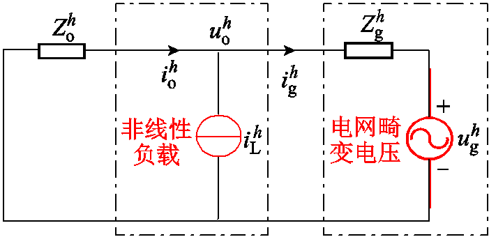
图2 谐波等效电路
Fig.2 Circuit of the harmonic-domain
根据图2得到VSG第h次本地电压谐波 与并网电流谐波
 分别为
分别为
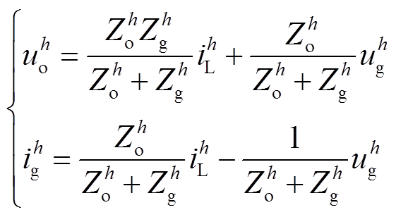 (1)
(1)
如式(1)所示,大量非线性负载的接入易导致本地电压uo与并网电流ig发生严重畸变。此外,加上畸变电网并联支路的影响,其电能质量问题可能会进一步恶化,从而导致uo与ig的THD大大超出允许阈值(≤5%),进而严重威胁分布式电源对关键负荷及电网的供电质量。因此有必要设计一种针对各次谐波的控制策略以提高分布式电源的并网适应性。
本节阐述本地电压谐波与并网电流谐波两者在控制上所固有的制约关系。常规电压控制型逆变器谐波抑制原理如图3所示,其中 为VSG的谐波补偿电压。
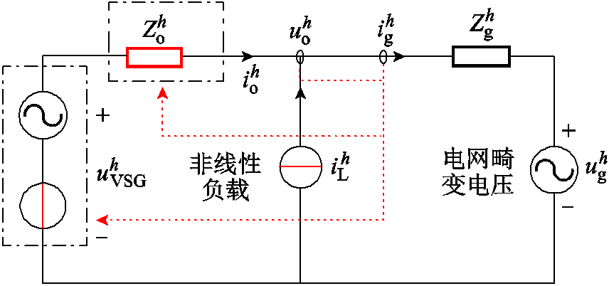
图3 常规电压控制型逆变器谐波抑制原理
Fig.3 Conventional harmonics suppression for voltage controlled-inverter
由图3得到对应的本地电压谐波 与并网电流谐波
 分别为
分别为
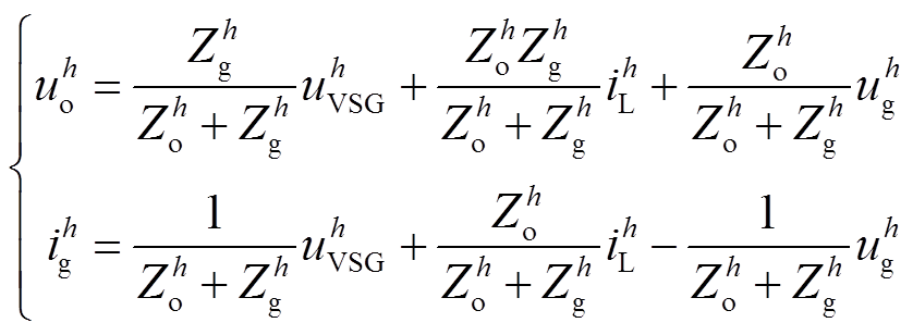 (2)
(2)
由于在谐波频域中逆变器输出谐波阻抗为感性特性,为便于分析,在本文中 ,其中Lo与ωh分别为逆变器输出等效电感与h次谐波角频率。类似地,并网线路谐波阻抗同样可视为感性特性,即
 ,其中Lg为并网线路电感。此外,为抵消电网电压畸变
 的影响,谐波电压补偿量
 应与
应与 相位一致。并且在最严重情况下,
 与uh g相位应超前90°于非线性负载电流
 。由此得到式(2)对应的关系如图4所示。
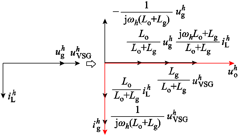
图4 输出电压谐波 与并网电流谐波
Fig.4 Vector diagram of ![]() and
and  for harmonic analysis
基于图4,得到
 (3)
(3)
式中, 分别为
分别为 的有效值。进一步,得到在特定电网电压畸变
 与非线性负载电流
 下各次谐波含量(Harmonic Ratio, HR)为
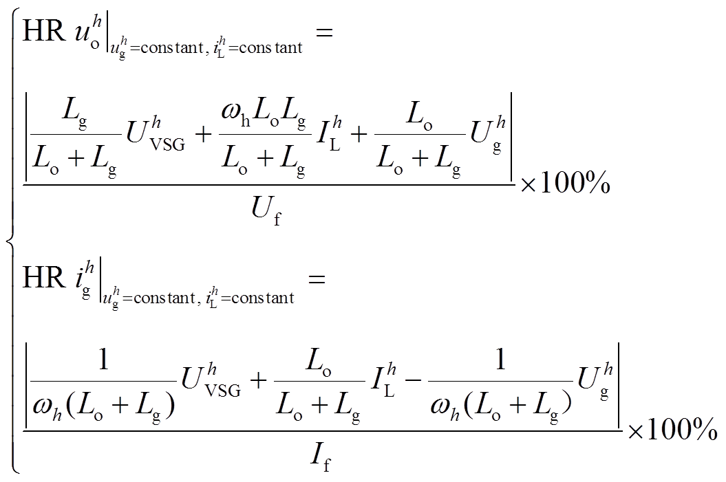 (4)
(4)
考虑到逆变器谐波电压补偿量 与输出谐波阻抗
 均可从控制角度实现灵活改变[13],由此得到当
 与
与 分别为额定电压电流基波幅值5%,即
 ,
, 时,使得本地电压谐波
 与并网电流谐波
 满足5%阈值要求的
 与
与 取值范围如图5所示(Lg=2.3 mH)。
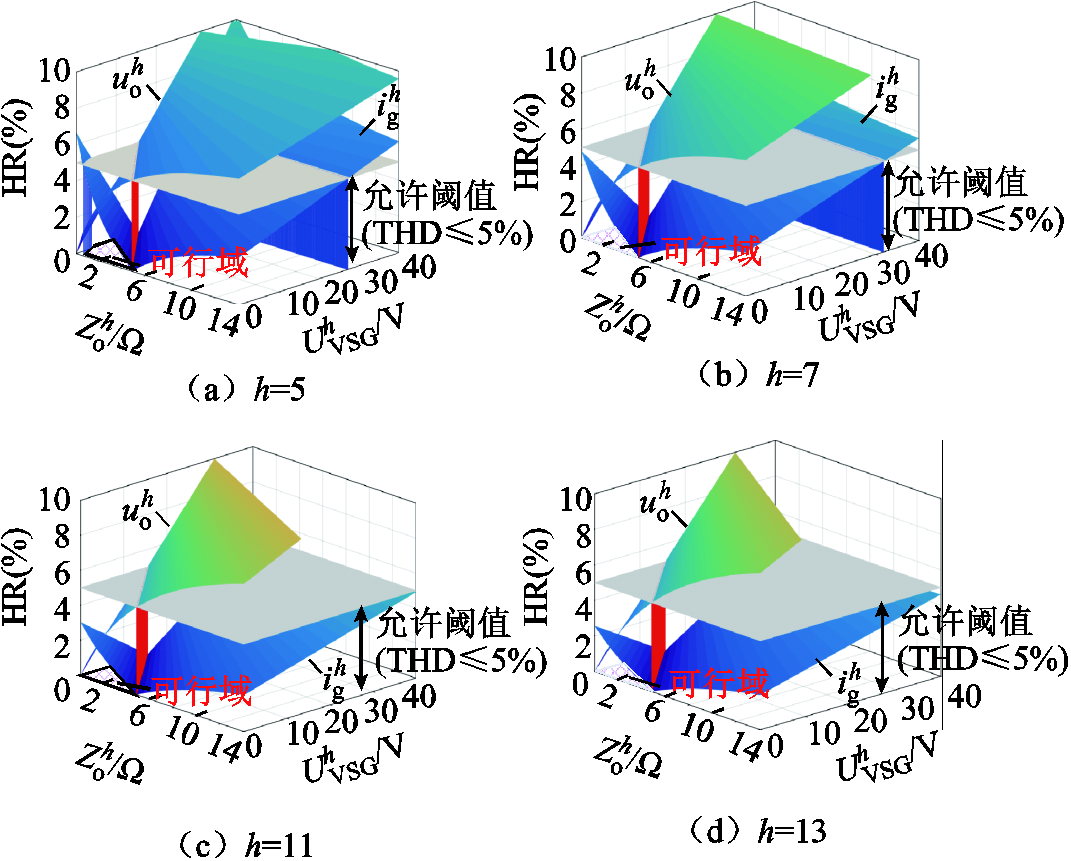
图5 改变 与
与 时
时 与
与 的HR变化趋势
Fig.5 Resultant HR for  and
and  in case of different
  and
and 
图5分别显示了5、7、11、13次本地电压谐波和并网电流谐波与VSG的可控量 和
和 的关系。对于每一特定谐波,其中投影至底部的红色阴影区域为能够使
 与
与 满足小于等于5%阈值的
 与
与 可行域。然而,当系统谐波源进一步恶化,该可行域将逐渐减小直至消失。以5次谐波为例进行说明,当电网电压畸变量
 与本地非线性负载电流
 分别从5%增加到10%基波幅值时,分别画出当
 ,
, 时与当
时与当 ,
, 时,满足
时,满足 与
与 的
的 与
与 的取值区域示意图如图6所示。

图6 两种![]() 与
与 设置下,满足
 与
与![]() 的
的 与
与 的取值区域
的取值区域
Fig.6 Feasible ranges of and
and  to meet the requirements of
 and
and ![]() for two sets of
for two sets of 
图6中红色阴影区域为并网电流谐波小于等于5%的 与
与 取值范围(定义为可行域A),蓝色阴影区域为本地电压谐波小于等于5%的
 与
与 取值范围(定义为可行域B)。可见,当系统谐波源恶化,可行域A与可行域B朝相反方向移动,使得相比于图6a,图6b的可行域A与可行域B已无交集,说明电网畸变电压与本地非线性负载为两种相互制约的谐波源。从控制的角度,对应的谐波抑制策略应能够实现以下目标:①使逆变器输出谐波阻抗
 减小,从而逆变器侧能够吸收大部分的本地非线性负载电流;②逆变器本地电压谐波应尽可能小,以保证本地关键负载的供电质量;③并网等效谐波阻抗应尽可能大,以减小并网电流谐波含量。总之,亟须提供一种能够同时提高逆变器本地电压与并网电流电能质量的控制策略。
根据叠加原理,线性电路可以分解在不同频率下单独分析。考虑到谐波的精确提取对控制效果起着重要作用,有别于常规采用的离散型傅里叶变换(Discrete Fourier Transform, DFT)、小波变换、神经网络与卡尔曼滤波等智能型谐波提取方法,本文基于MHSCO同时提取电压和电流中的谐波序列,得到第h次谐波的观测值为[27]
 (5)
(5)
式中,vk为第k个采样周期中输入电压或者电流信号; 为第k+1个采样周期中第h次电压谐波或电流谐波观测值;w为电网电压角频率;wc为观测器的剪切频率;Ts为采样周期;l为谐波次数,l=+1, -5, +7, -11,
 , 6m+1,m=0,1,2,
 ;n为待观测的谐波数。与当前一种典型的滑窗迭代DFT谐波方法对比,其实现方程如式(6)所示[28]。
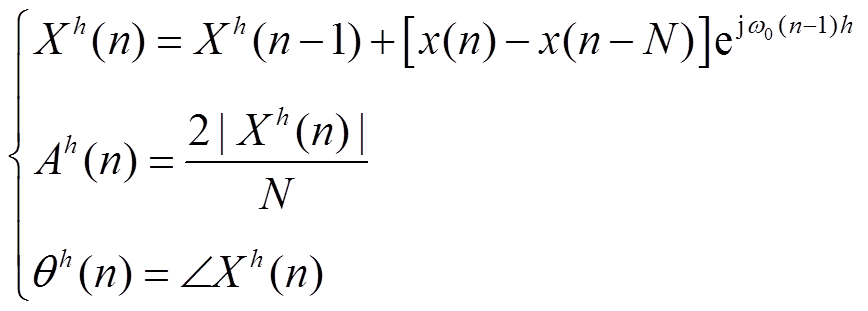 (6)
(6)
式中, 为旋转因子;ω0=2π/N;N为一个周期的变换点数;Xh(n)为第h次谐波;Ah(n)为第h次谐波幅值;θh(n)为h次谐波相角。
设置输入信号Vabc在幅值为1,频率为50 Hz基波基础上叠加30%的5次谐波、20%的7次谐波及10%的11次谐波。Vabc在t=2 s时刻基波幅值跃升为2倍。滑窗迭代DFT的采样频率为6 400 Hz,变换点数N取128;MHSCO采样频率一致,剪切频率ωc取100π,得到两种方法的时变响应特性如图7所示。可见,基于滑窗迭代DFT方法提取的5、7与11次谐波在时变输入信号下约10、12与16个周波内稳定,而基于MHSCO提取相应谐波可缩短至4、5与7个周波内。显然,基于MHSCO与基于滑窗迭代DFT提取谐波的精确度相近,而基于MHSCO具有较好的时变响应特性。同时相比于一些智能型谐波提取算法如小波变换、神经网络、卡尔曼滤波器等,MHSCO算法更简易,便于工程实现[27]。
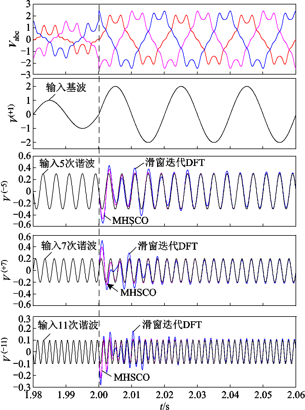
图7 MHSCO 与滑窗迭代DFT提取谐波序列效果对比
Fig.7 Comparison of of MHSCO and Sliding-window iteration DFT for the extraction of harmonic sequences
本文所提基于MHSCO的混合谐波抑制策略等效电路如图8所示,由谐波电压反馈控制环与流控电压补偿环组成。
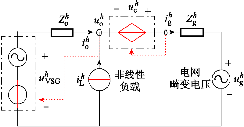
图8 本文所提谐波抑制策略等效电路
Fig.8 Equivalent circuit with the proposed harmonic suppression method
根据图8可将式(1)修正为
 (7)
(7)
理论上,令 可消除非线性负载电流
 对本地电压与并网电流的影响,此时本地电压谐波
 中的
中的 项与并网电流谐波
 中的
中的 项为0。类似地,电网畸变电压
 对本地电压与并网电流的影响也可通过令
 进行抵消,这可以通过如图8所示在本地母线与电网侧之间引入一个流控电压补偿器来实现。据此,本文所提分布式电源混合谐波控制策略控制结构如图9所示。首先基于MHSCO提取逆变器本地电压谐波
 与输出电流谐波
 ,经过谐波电压反馈控制环得到谐波电压参考值,然后将VSG基波电压参考值与谐波电压参考值相加得到总的本地电压参考值
 ,从而补偿在逆变器输出谐波阻抗上的压降。同时,所设计的流控电压补偿环通过检测并网电流谐波而产生一个电压谐波补偿量uc以抵消电网畸变电压的影响。在所提控制策略下,并网逆变器等效输出阻抗为
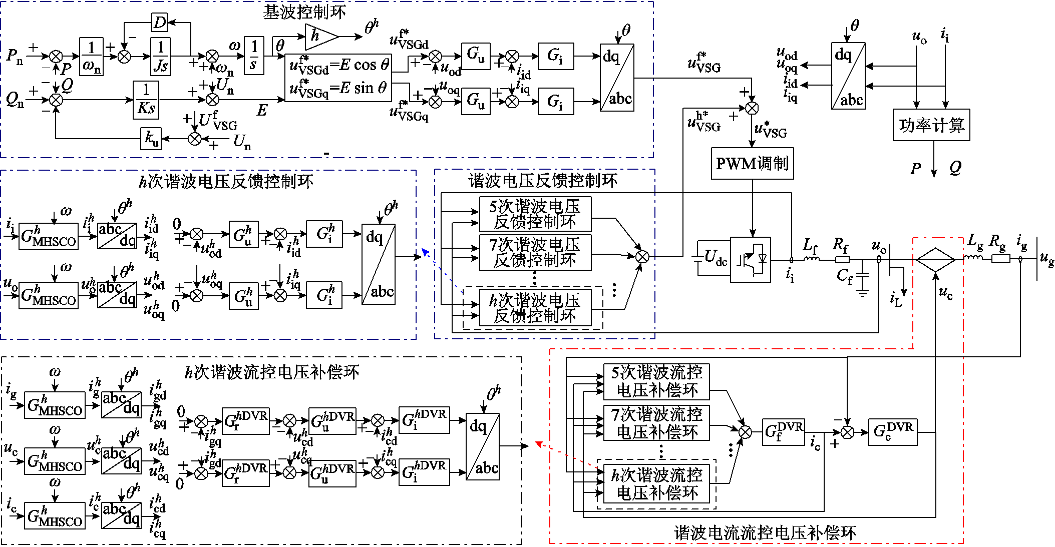
图9 分布式电源混合谐波抑制策略总体控制结构
Fig.9 Overall control structure of hybrid harmonic suppression strategy for distributed generation
 (8)
(8)
式中, 为调制比;Gf与Gc分别为滤波电感与电容支路;
 与
与 为PI控制器,
 ,
, ;
; 。为说明所提控制策略原理,将有、无该策略的逆变器等效输出阻抗进行对比,结果如图10所示。显然,在本文所提控制策略下,逆变器在h次谐波处的输出阻抗显著减小,也因此能够吸收更多的谐波负载电流而产生更小的谐波压降,从而提高本地电压质量。
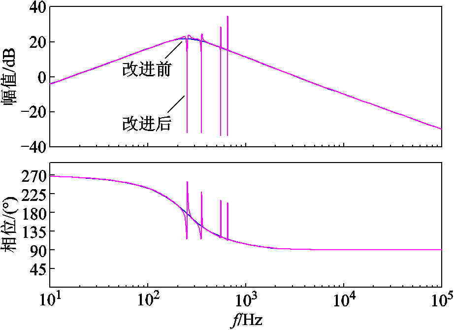
图10 有与无所提谐波电压反馈控制环路下Zo的伯德图
Fig.10 Bode plot of Zo with and without the proposed method
另一方面,考虑电网畸变电压uh g引起的逆变器并网电流谐波,设计一种流控电压补偿环路以产生补偿电压uc,抵消电网畸变电压的影响。如图10可以得到并网支路在dq坐标系的模型为
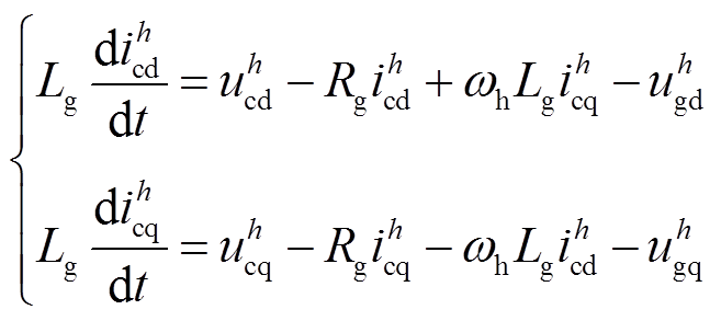 (9)
(9)
式中, 与
与 分别为
分别为 与
与 的dq分量。当
 时,即代表本文流控电压补偿环所产生的电压补偿量
 可完全抵消电网畸变电压
 的影响,此时并网谐波电流为0,即
 。本文中,将h次谐波的并网线路谐波阻抗表示为
 ,其中Rg、Lg分别为并网线路电阻与电感,ωh与ωn分别为谐波角频率与基波角频率。对于三相电网而言[27],其主要的谐波次数h=5,7,11,13,
 ,此时
,此时 ,因此可近似视为
 ,且当谐波阶数越高,其并网线路谐波阻抗
 的感性特性越明显,即使是在线路呈现阻感性的配电网中,该规律仍适用。基于此,根据式(9)可知电压补偿量d轴分量
 与并网谐波电流q轴分量
 强耦合,而电压补偿量q轴分量
 与并网谐波电流d轴分量
 强耦合,因此设计如式(10)的谐波电流控制器,产生对应的电压补偿量。
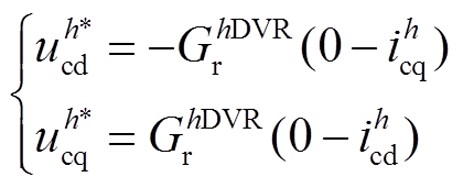 (10)
(10)
式中, 与
与 分别为谐波电压补偿量参考值的dq分量;
 为PI控制器,
 、
、 分别为比例系数与积分系数。然后采用典型电压电流双环对该参考值进行跟随。对应的并网电流与电网电压传递函数如式(11)所示。
 (11)
(11)
式中,khDVR pwm为调制比;GDVR f与GDVR c分别为流控电压补偿器的电感与电容;GhDVR u与GhDVR i为PI控制器, ;G g为并网线路,
 ,
,
 。
。
对比有、无流控电压补偿器的等效并网导纳伯德图如图11所示。可见,在本文所提方法下的等效并网导纳在h次谐波频率处的幅值显著减小,说明电网电压畸变量 所引起的并网电流谐波将能够被有效抑制。
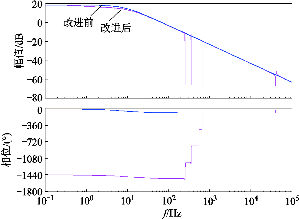
图11 有无所提流控电压补偿环路下Yg的伯德图
Fig.11 Bode plots of Yg with and without the proposed method
综上所述,本文所提方法分别通过重塑逆变器等效输出阻抗与并网导纳,实现同时对逆变器本地电压谐波与并网电流谐波的有效抑制。本文所设计的谐波电压反馈控制环与流控电压补偿环中不涉及线路参数,算法复杂度较低,且具有一定的控制鲁棒性与适应性,在电网电压畸变量、本地非线性负载与并网线路阻抗变化下仍具有良好谐波抑制效果。值得注意的是,基于叠加原理,所提谐波抑制环路具有良好的兼容性,不会对逆变器原有基波的控制环路产生影响。
本节建立系统的小信号模型并分析参数摄动对系统稳定性的影响。所述小信号模型包括逆变器、并网线路与控制器三个部分。首先,建立逆变器h次谐波等效电路在dq坐标系下的模型为
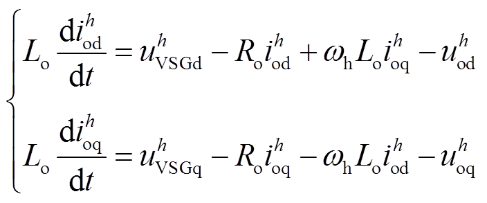 (12)
(12)
式中, 与
与 分别为逆变器输出电流谐波与本地电压谐波的dq分量;R o与L o分别为逆变器的等效输出电阻与电感。本地电压谐波参考值为
 (13)
(13)
式中,xd、xq为PI控制器的状态变量; 分别为比例系数与积分系数。流控电压补偿器的补偿电压为
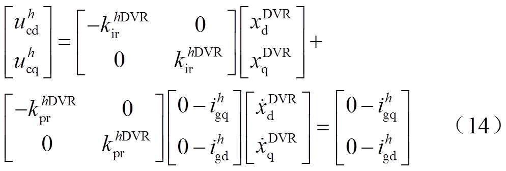
式中, 为PI控制器的状态变量。建立并网线路谐波域dq坐标系模型,有
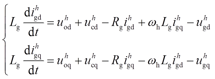 (15)
(15)
式中, 分别为并网电流谐波
 的d、q分量。联立式(12)~式(15),并线性化得到系统小信号模型,有
 (16)
(16)
式中, ;A为系统状态矩阵。基于系统小信号模型可研究参数对系统动态特性的影响。因实际中并网线路参数容易变化,本文主要研究并网线路电感Lg的影响。基于表1所示参数,得到Lg在0.5~3.1 mH之间变化时系统特征根轨迹如图12所示。
表1 系统与控制参数
Tab.1 System and control parameters

参数数值参数数值 额定容量SN/(kV·A)30并网线路电感Lg/mH2.3 VSG直流电压Udc/V800 采样周期Ts/ms50 滤波电感Lf /mH2 非线性负载电阻Rnl/Ω25 滤波电容Cf /mF50 非线性负载电容Cnl/mF400 并网线路电阻Rg/Ω0.12 非线性负载电感Lnl/mH0.6 谐波控制器参数h=5h=7 kh pu, kh iu, kh pi1, 100, 201, 80, 15 khDVR pr, khDVR ir, khDVR pu, khDVR iu, khDVR pi0.5, 150, 2, 100, 180.5, 100, 2, 100, 15
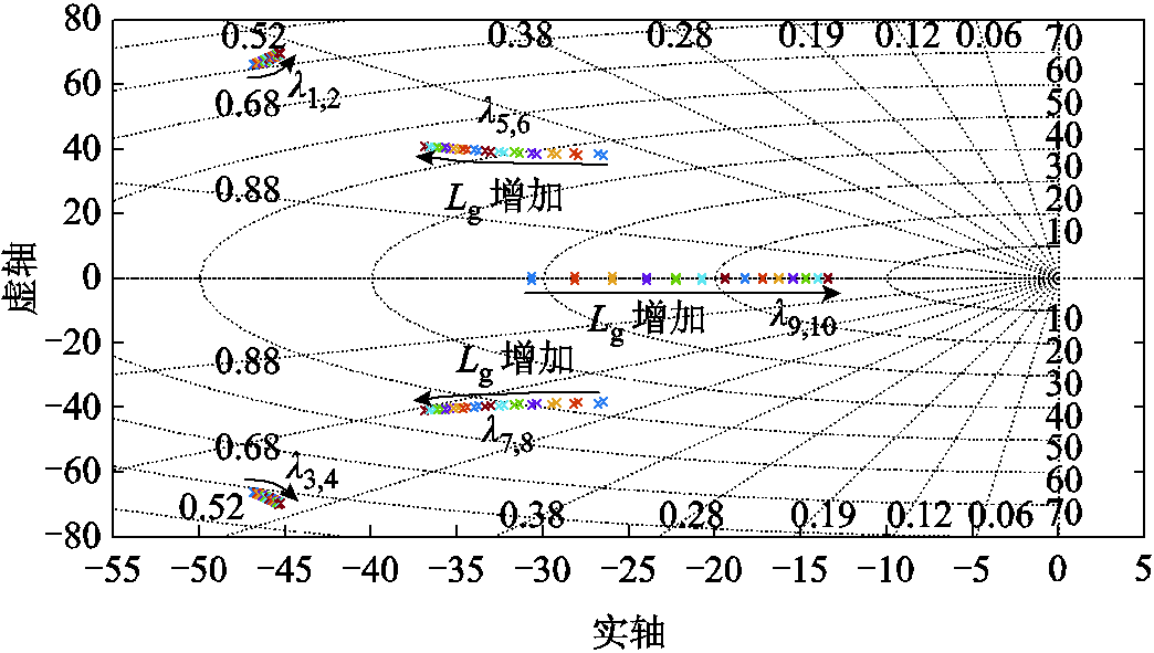
图12 并网线路电感Lg从0.5 mH增加至3.1 mH时系统特征根轨迹
Fig.12 Eigenvalues locus with grid impedance: 0.5 mH ≤Lg≤3.1 mH
由图12可见,随着Lg增加,主导特征根λ5,6,7,8朝向远离虚轴方向移动,显示出更好的系统稳定性。然而,特征根λ9,10在相同情况下却朝着虚轴方向靠近,表明所提控制策略对参数Lg的摄动具有一定的鲁棒性。因此,在实际中Lg的取值不应过大或者过小,否则都不利于系统的稳定。
为验证所提控制策略的有效性,搭建了如图13所示基于RT-LAB的半实物仿真系统进行仿真测试。在OPAL-RT仿真主机中运行图1所示主电路部分,基于TMS320F28377 DSP编程实现逆变器控制策略部分,仿真主机与控制器间通过模拟与数字板卡实现模拟量采集与控制指令下达。系统电路参数与主要控制参数见表1。本文假设电网畸变电压中5、7次谐波占主要成分,其幅值分别为基波电压的20%与10%。仿真中的波形通过仿真主机模拟接口外接Tektronix MDO3020示波器进行观察。
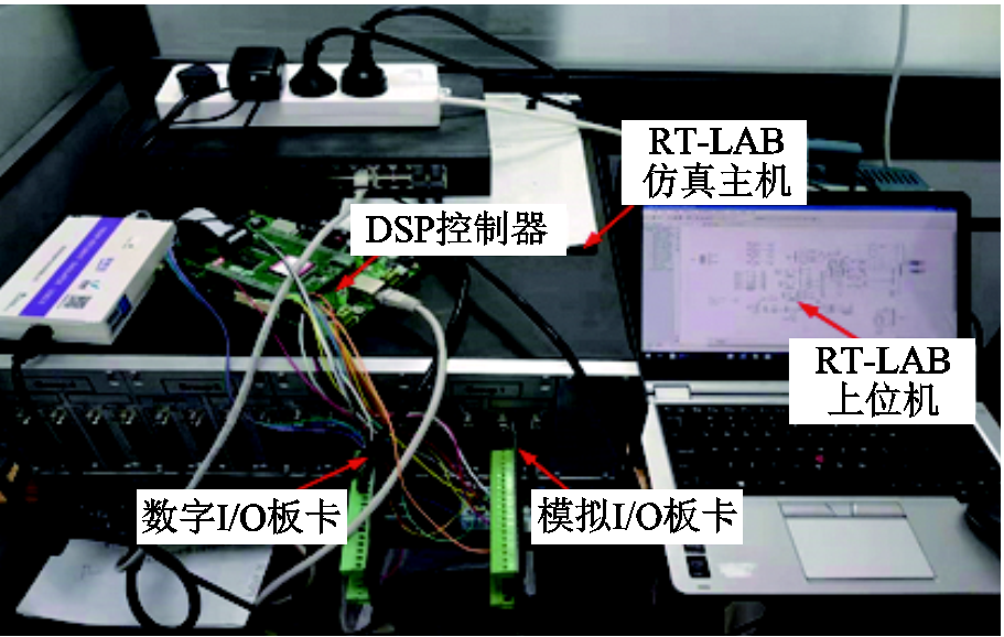
图13 基于RT-LAB的半实物仿真系统
Fig.13 Hardware in the loop simulation system based on RT-LAB
该实验场景下,本文所提谐波电压反馈控制环在t=4 s投入,随后在t=4.5 s投入所提电网流控电压补偿环,仿真结果如图14所示。

图14 本地电压谐波与并网电流谐波抑制实验结果
Fig.14 Simulation results of voltage and current harmonics suppression
图14a显示,在投入所提控制策略之前,VSG的本地电压与并网电流发生严重畸变,其畸变率分别达到了8.90% 与15.35%。理论上,在仅加入谐波电压反馈控制环时,即仅减小等效输出谐波阻抗 ,如图5中曲面图所示,对于5、7、11或13次任意次谐波而言,当令
 为0,仅通过减小等效输出谐波阻抗
 来抑制PCC电压谐波
 时,理想状态下当
 时可达到
时可达到 ,但并网电流谐波
 反而会呈现增加的趋势(见图5中任意曲面图的
  断面)。在实验中,如图14b所示,当仅加入谐波电压反馈控制环时,5、7次电压谐波
 分别从7.5%Uf、4.8%Uf下降至0.5%Uf、1%Uf,而5、7次并网电流谐波
 却从15%If、3.5%If上升到了25%If、7.5%If。理论与实验差异在于
 并没有被完全抑制至0,且
 已经远远超出5%的上限,这是由于实验中模拟量采样产生的量化噪声、数学运算的截断误差等固有影响所致,且实验中叠加的电网畸变电压中5、7次谐波的幅值分别为20%Uf与10%Uf,大于理论部分设置的5%Uf。实验中当同时加入谐波电压反馈控制环与电网流控电压补偿环之后,
 与
与 分别被抑制至2.42%与2.24%,如图14c所示。这是由于在本文控制策略下等效输出谐波阻抗
 与等效并网谐波导纳
 同时接近于0,如图10、图11所示,而
 与
与 没有完全等于0,是因为本文实验中只投入了对主要的5、7次谐波的控制环路,因此在抑制5、7次谐波时,11、13次谐波会稍有上升。
为分析本文所提控制策略对并网线路电感Lg的鲁棒性,对Lg从2.3 mH减小至1.8 mH的控制效果进行了实验,实验结果如图15所示。对比图14a与图15a可见,在无谐波抑制策略下,由于Lg的减小使得VSG本地电压与并网电流的THD分别从8.90%上升至10.14%、15.35%上升至17.17%。当投入所提谐波电压反馈控制环后,本地电压下降至 2.41%,如图15b所示,与图14b结果接近。然而,并网电流THD却上升到了32.25%,比图14b明显恶化。当投入电网流控电压补偿环后,本地电压与并网电流THD分别下降至2.69%与2.83%,偏低于5%的阈值要求,表明所提控制策略对电网线路参数变化具有一定的鲁棒性。同时注意到本算例中将Lg从2.3 mH减小至1.8 mH,谐波源大小不变,稳定时uh s与ih g虽仍能被抑制至2.69%与2.83%,但相比于Lg=2.3mH时却有所增加,这是受控制器参数整定及误差放大等因素的影响所致。

图15 并网线路电感Lg变化时谐波抑制实验结果
Fig.15 Simulation results of the robustness against Lg variation
为验证所提控制策略应对负载变化的适应性,当t=5 s时在PCC接入10 kW线性负载,随后在t=5.3 s切除,同时本地非线性负载增加一倍。本文方法与常规基于阻抗重塑方法的谐波抑制[23]效果分别如图16、图17所示。
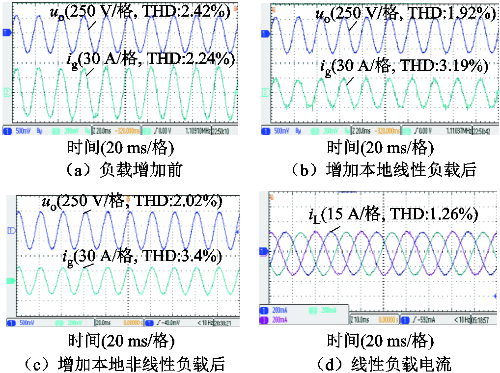
图16 负载变化时所提谐波抑制策略的实验结果
Fig.16 Simulation results of the robustness to load variation of the proposed method
实验结果对比见表2。当PCC增加10 kW本地线性负载时,本地线性负载比例增加会使PCC电压畸变量下降,同时流向电网的电流基波成分减小会导致并网电流THD上升。在此情形下,采用本文方法本地电压THD下降比率为20.7%,比常规方法更大,且并网电流THD上升比率为42.4%,比常规方法更小。当PCC非线性负载增加一倍时,本地非线性负载比例的增加会使得PCC电压畸变量上升,并增加并网电流的谐波含量。在此情形下,常规方法相比于本文方法,本地电压与并网电流THD上升比率均明显较高,且其并网电流THD已经超出5%的上限。该实验结果对比说明了本文方法能够实现对本地电压谐波与并网电流谐波的并发抑制,且在负载波动时具有更好的负载适应性。

图17 负载变化时常规谐波抑制策略的实验结果
Fig.17 Simulation results of the robustness to load variation of the comparison method
表2 实验结果对比
Tab. 2 Comparison of experimental results (%)

对比变量对比方法初始线性负载增加波动比非线性负载增加波动比 THD1THD2THD2-THD1THD3THD3-THD2 THD1THD2 本地电压常规方法3.082.67-13.33.6536.7 本文方法2.421.92-20.72.025.2 并网电流常规方法2.885.3585.86.317.8 本文方法2.243.1942.43.46.6
本文针对分布式电源并网逆变器本地电压谐波与并网电流谐波的并发治理问题,提出一种混合谐波抑制策略。通过理论分析、实验研究得到以下结论:
1)提出的混合谐波抑制策略分别通过谐波电压反馈控制环与电网流控电压补偿环实现对本地电压谐波与并网电流谐波的协同抑制,可保证电压与电流THD在5%以内。
2)减小并网线路阻抗Zg,或施加本地负载扰动,电压与电流THD仍被抑制在较低水平,具有一定的控制适应性与鲁棒性。
3)本文理论部分并未就谐波调节容量的制约性进行研究,但实际中其谐波调节容量会受到分布式电源实时输出功率的影响,需权衡输出基波功率与谐波调节容量之间的关系。
参考文献
[1] 李文番, 张国钢, 钟浩杰, 等. 一种高频率分辨率的谐波、间谐波分析模型[J]. 电工技术学报, 2022, 37(13): 3372-3379, 3403. Li Wenfan, Zhang Guogang, Zhong Haojie, et al. A high frequency resolution harmonic and interharmonic analysis model[J]. Transactions of China Electrotechnical Society, 2022, 37(13): 3372-3379, 3403.
[2] 李勇, 刘珮瑶, 胡斯佳, 等. 基于感应滤波的光伏电站谐波谐振抑制方法[J]. 电工技术学报, 2022, 37(15): 3781-3793. Li Yong, Liu Peiyao, Hu Sijia, et al. Harmonic resonance damping method of photovoltaic power station based on inductive filtering[J]. Transactions of China Electrotechnical Society, 2022, 37(15): 3781-3793.
[3] IEEE Recommended Practices and Requirements for Harmonic Control in Electrical Power Systems: 519-1992[S]. Institute of Electrical and Electronics Engineers, 1992.
[4] 国家技术监督局. 电能质量公用电网谐波: GB/T 14549—1993[S]. 北京: 中国标准出版社, 1994.
[5] Hashempour M M, Savaghebi M, Vasquez J C, et al. A control architecture to coordinate distributed generators and active power filters coexisting in a microgrid[J]. IEEE Transactions on Smart Grid, 2016, 7(5): 2325-2336.
[6] He Jinwei, Li Yun wei, Wang Ruiqi, et al. A measurement method to solve a problem of using DG interfacing converters for selective load harmonic filtering[J]. IEEE Transactions on Power Electronics, 2016, 31(3): 1852-1856.
[7] Campos-Gaona D, Peña-Alzola R, Monroy-Morales J L, et al. Fast selective harmonic mitigation in multifunctional inverters using internal model controllers and synchronous reference frames[J]. IEEE Transactions on Industrial Electronics, 2017, 64(8): 6338-6349.
[8] 耿乙文, 田芳芳, 孙帅, 等. 一种基于虚拟同步发电机的电流谐波抑制方法[J]. 电工技术学报, 2018, 33(5): 1040-1050. Geng Yiwen, Tian Fangfang, Sun Shuai, et al. A method of current harmonics suppression based on VSG[J]. Transactions of China Electrotechnical Society, 2018, 33(5): 1040-1050.
[9] 陈杰, 章新颖, 闫震宇, 等. 基于虚拟阻抗的逆变器死区补偿及谐波电流抑制分析[J]. 电工技术学报, 2021, 36(8): 1671-1680. Chen Jie, Zhang Xinying, Yan Zhenyu, et al. Dead-time effect and background grid-voltage harmonic suppression methods for inverters with virtual impedance control[J]. Transactions of China Electrotechnical Society, 2021, 36(8): 1671-1680.
[10] 徐健, 曹鑫, 郝振洋, 等. 基于电网谐波电压前馈的虚拟同步整流器电流谐波抑制方法[J]. 电工技术学报, 2022, 37(8): 2018-2029. Xu Jian, Cao Xin, Hao Zhenyang, et al. A harmonic-current suppression method for virtual synchronous rectifier based on feedforward of grid harmonic voltage[J]. Transactions of China Electrotechnical Society, 2022, 37(8): 2018-2029.
[11] 孟令辉, 舒泽亮, 闫晗, 等. 基于特征次谐波补偿的单相统一电能质量调节器并联变换器控制策略[J].电工技术学报, 2020, 35(24): 5125-5133. Meng Linghui, Shu Zeliang, Yan Han, et al. Control strategy for single-phase unified power quality conditioner of parallel converter based on specific order harmonics compensation[J]. Transactions of China Electrotechnical Society, 2020, 35(24): 5125-5133.
[12] Zhong Qingchang. Harmonic droop controller to reduce the voltage harmonics of inverters[J]. IEEE Transactions on Industrial Electronics, 2013, 60(3): 936-945.
[13] Micallef A, Apap M, Spiteri-Staines C, et al. Mitigation of harmonics in grid-connected and islanded microgrids via virtual admittances and impedances[J]. IEEE Transactions on Smart Grid, 2017, 8(2): 651-661.
[14] 戴喜良. 基于虚拟电容补偿的级联型有源电力滤波器控制策略[J]. 电气技术, 2021, 22(6): 49-53. Dai Xiliang. Cascaded active power filter control strategy based on virtual capacitor compensation[J]. Electrical Engineering, 2021, 22(6): 49-53.
[15] He Jinwei, Li Yunwei, Munir M S. A flexible harmonic control approach through voltage-controlled DG–grid interfacing converters[J]. IEEE Transactions on Industrial Electronics, 2012, 59(1): 444-455.
[16] 涂春鸣, 杨义, 肖凡, 等. 非线性负载下微电网主逆变器输出侧电能质量控制策略[J]. 电工技术学报, 2018, 33(11): 2486-2495. Tu Chunming, Yang Yi, Xiao Fan, et al. The output side power quality control strategy for microgrid main inverter under nonlinear load[J]. Transactions of China Electrotechnical Society, 2018, 33(11): 2486-2495.
[17] 石荣亮, 张兴, 刘芳, 等. 不平衡与非线性混合负载下的虚拟同步发电机控制策略[J]. 中国电机工程学报, 2016, 36(22): 6086-6095. Shi Rongliang, Zhang Xing, Liu Fang, et al. A control strategy for unbalanced and nonlinear mixed loads of virtual synchronous generators[J]. Proceedings of the CSEE, 2016, 36(22): 6086-6095.
[18] 张辉, 张瑞雪. 非线性负载下虚拟同步发电机的控制策略[J]. 电气传动, 2019, 49(10): 48-50. Zhang Hui, Zhang Ruixue. Control strategy for the nonlinear load of virtual synchronous generator[J]. Electric Drive, 2019, 49(10): 48-50.
[19] Sou W K, Choi W H, Chao Chiwa, et al. A deadbeat current controller of LC-hybrid active power filter for power quality improvement[J]. IEEE Journal of Emerging and Selected Topics in Power Electronics, 2020, 8(4): 3891-3905.
[20] Yan Qingzeng, Wu Xiaojie, Yuan Xibo, et al. An improved grid-voltage feedforward strategy for high-power three-phase grid-connected inverters based on the simplified repetitive predictor[J]. IEEE Transactions on Power Electronics, 2016, 31(5): 3880-3897.
[21] 赵强松, 陈莎莎, 周晓宇, 等. 用于并网逆变器谐波抑制的重复-比例复合控制器分析与设计[J]. 电工技术学报, 2019, 34(24): 5189-5198. Zhao Qiangsong, Chen Shasha, Zhou Xiaoyu, et al. Analysis and design of combination controller based on repetitive control and proportional control for harmonics suppression of grid-tied inverters[J]. Transactions of China Electrotechnical Society, 2019, 34(24): 5189-5198.
[22] Peng Yunjian, Sun Weijie, Deng Feiqi. Internal model principle method to robust output voltage tracking control for single-phase UPS inverters with its SPWM implementation[J]. IEEE Transactions on Energy Conversion, 2021, 36(2): 841-852.
[23] Zhou Leming, Shuai Zhikang, Chen Yandong, et al. Impedance-based harmonic current suppression method for VSG connected to distorted grid[J]. IEEE Transactions on Industrial Electronics, 2020, 67(7): 5490-5502.
[24] 钟庆昌. 虚拟同步机与自主电力系统[J]. 中国电机工程学报, 2017, 37(2): 336-349. Zhong Qingchang. Virtual synchronous machines and autonomous power systems[J]. Proceedings of the CSEE, 2017, 37(2): 336-349.
[25] 吕志鹏, 盛万兴, 刘海涛, 等. 虚拟同步机技术在电力系统中的应用与挑战[J]. 中国电机工程学报, 2017, 37(2): 349-360. Lü Zhipeng, Sheng Wanxing, Liu Haitao, et al. Application and challenge of virtual synchronous machine technology in power system[J]. Proceedings of the CSEE, 2017, 37(2): 349-360.
[26] Bidram A, Davoudi A, Lewis F L, et al. Distributed cooperative secondary control of microgrids using feedback linearization[J]. IEEE Transactions on Power Systems, 2013, 28(3): 3462-3470.
[27] Quan Xiangjun, Dou Xiaobo, Wu Zaijun, et al. A concise discrete adaptive filter for frequency estimation under distorted three-phase voltage[J]. IEEE Transactions on Power Electronics, 2017, 32(12): 9400-9412.
[28] 刘华吾, 胡海兵, 邢岩. 有限字长对滑动窗DFT稳定性的影响研究[J]. 电工技术学报, 2016, 31(11): 22-31. Liu Huawu, Hu Haibing, Xing Yan. Research of finite-word-length effects on the stability of the sliding DFT[J]. Transactions of China Electrotechnical Society, 2016, 31(11): 22-31.
Abstract Nowadays, more and more power-electronics-interfaced distributed generations (DGs) and new loads are connected to the distribution network, which endows the electricity grids superior flexibility and controllability. However, with the penetration of DGs and intensive utilization of nonlinear loads, the resulting grid distortion will seriously threaten the grid current quality of DGs and deteriorates the voltage of critical loads in the distribution network. Recently, few researches geared toward the quantitative analysis of the fundamental limitation in the dual harmonics suppression, nor the adaptability improvement of DGs in the presents of both the local nonlinear loads and distorted grid. To address these issues, this paper proposes a hybrid harmonic suppression scheme, which leads to substantially lower total harmonic distortion for both the local load voltage and the grid current at the same time.
First, the constraint involved in the simultaneous elimination of distortion for both the inverter local voltage and the grid current is quantitatively analyzed. The conventional method to restrain local voltage harmonic  was to abate the inverter output harmonic impedance
  via a negative feedforward. However, the suppression of grid current harmonic
  might be compromised since
  is also nonlinear with
  from the numerical expression. Therefore, the restriction of the two distortions entirely and simultaneously appears infeasible for the intrinsic contradiction by using one control variable
  Then, a hybrid harmonic suppression based on multiple harmonic sequence component observer (MHSCO) is proposed, which mainly consists of a local voltage harmonic control loop and a grid current-controlled voltage compensator. MHSCO is introduced rather than conventional DFT for the accurate and exhaustive extraction of individual harmonics simultaneously, so that individual harmonic components in grid current and local voltage are extracted respectively and with superior time-varying response characteristics. A local voltage harmonic control loop is designed to scale down
  , while a grid current-controlled compensator is elaborated to reduce the harmonic admittance
  via an additional voltage. The system small-signal model is deduced and the adaptability of proposed strategy to the perturbation of grid impedance Lg is studied. The eigenvalue locus indicates Lg should be maintained neither too large nor too small to ensure system stability.
Hardware in the loop simulation is performed subsequently. The local voltage harmonic control loop and grid current-controlled compensator of the proposed strategy are activated successively in the first simulation scenario. When the local voltage harmonic control loop is first operated,  decrease from 8.9% and to 2.29%, while
  increase from 15.35% to 26.13% because of constraint of the two harmonics. When the grid current-controlled compensator is added at the same time,
 and
and are suppressed to 2.42% and 2.24% respectively. In the subsequent simulation scenario, Lg is decreased from 2.3 mH to 1.8 mH to investigated the robust against the variation of grid impedance. The THDs of us and ig are maintained low at 2.69% and 2.83% in this scenario, respectively. In the case of load fluctuations, the effectiveness of proposed strategy and conventional strategy is compared and evaluated. When the proportion of linear load at PCC increases, the THD of us drops by 20.7% with the proposed method, which is greater than that of the conventional method 13.3%, while the THD of ig increases by 42.4% with the proposed method, lower than the that of the conventional method 85.8% . When nonlinear load doubles, the THD of us and igof the conventional method rise by 36.7% and 17.8%, which are significantly higher than those of the proposed method 5.2% and 6.6%.
The following conclusions can be drawn from the simulation analysis: (1) The concurrent suppression of voltage harmonics and grid current harmonics can be achieved with the proposed strategy, thus ensuring the power quality of the inverter and the local critical loads. (2) The THD of local voltage and grid current maintained low with a small grid impedance. In this sense, the proposed control strategy is robust to the perturbation of grid impedance to a certain extent. (3) Compared with conventional control methods, proposed method exhibits lower volatility of THD under load variation, which indicate superior adaptability against load fluctuation.
keywords:Distributed generations, nonlinear loads, distorted grid, harmonic suppression, grid-connected inverter
DOI:10.19595/j.cnki.1000-6753.tces.221907
中图分类号:TM464
广东电网有限责任公司2019年营销费资助项目(031900MY62190054)。
收稿日期 2022-10-08
改稿日期 2022-12-29
杨 权 男,1994年生,硕士研究生,研究方向为分布式发电技术、大功率电力电子技术。E-mail:1056911024@qq.com(通信作者)
梁永昌 男,1974年生,教授级高级工程师,研究方向为用电检查、电能质量治理。E-mail:13480080624@qq.com
(编辑 赫蕾)