 、损耗等效电阻R*和电流等效占空比D三个参数的数学模型。根据速度趋肤效应引入速度频率,将电枢动态运动模型转化为静态扫频模型并进行涡流场扫频分析,建立了全系统电气仿真模型。与试验结果进行对比,结果表明:电路模型、系统仿真与试验三者之间系统效率的误差小于3%。利用建立的等效电路模型和仿真模型对发射效率的影响因素进行分析,为发射效率优化设计提供了研究方法。
摘要 在发射装置串联电路模型的基础上,根据能量等效原理,提出了直流脉冲等效电路模型,建立了系统能量效率ηe与能量等效电阻、损耗等效电阻R*和电流等效占空比D三个参数的数学模型。根据速度趋肤效应引入速度频率,将电枢动态运动模型转化为静态扫频模型并进行涡流场扫频分析,建立了全系统电气仿真模型。与试验结果进行对比,结果表明:电路模型、系统仿真与试验三者之间系统效率的误差小于3%。利用建立的等效电路模型和仿真模型对发射效率的影响因素进行分析,为发射效率优化设计提供了研究方法。
关键词:电磁轨道发射 发射效率 等效电路模型 动态参数 系统仿真
电磁轨道发射装置是利用电磁力推动电枢在膛内高速运动的新型电磁发射装置,由于没有传统火药武器的声滞制约,可以突破传统火药武器的出口速度限制,实现超高速发射[1-2]。同时,由于结构简单、出口动能可控等优势,其已成为国内外军事装备领域的研究热点[3]。电磁轨道发射系统主要由脉冲电源和发射装置两部分组成,受限于电容储能密度、导轨电导率及导磁材料深度饱和等多种因素的影响,全系统的能量密度较低,体积和质量较大[4-5]。因此建立包括脉冲电源和发射装置的全系统电路模型,分析研究影响系统发射效率的因素,对电磁发射装置小型化、高效率具有非常重要的意义。
由于电磁发射过程中存在电流扩散和速度趋肤效应,导轨中的电流分布和空间磁场分布具有时变的特点,所以,系统参数也均为非线性时变参数。因此,准确地获得系统时变参数并建立有效的理论模型和仿真模型是进行系统分析的关键[6]。文献[7]建立了发射装置的数学模型,但没有从数学分析角度给出影响发射效率的各参数之间的关系。文献[8-10]给出了恒流和零出口电流两种工况下的效率计算方法,但没有建立全系统电气模型。文献[11]采用参数扫描的方式分析了系统发射效率,并进行了单目标最优解和双目标Pareto前沿分析,但该模型中没有考虑电感梯度等为时变参数的情况。本文通过引入能量等效电阻、损耗等效电阻R*及电流等效占空比D,建立了直流脉冲等效电路模型,通过有限元模型提取系统时变参数后建立全系统仿真模型,将电路模型、系统仿真和试验结果进行对比分析,检验了等效电路模型和仿真系统的正确性和有效性,为电磁轨道发射装置系统的效率研究和优化设计提供了方法。
电磁轨道发射装置工作原理如图1所示。图中,B1和B2分别指导轨内、外侧空间区域的磁感应强度。通电电枢在磁场中产生电磁推力从而推动电枢直线运动。根据图1并考虑系统杂散阻抗Zs可以得到发射装置串联电路原理图如图2所示。其中,Uc为外部供电电源,Us为电路杂散阻抗压降,Ua为电枢压降,Ur为导轨电阻电压,E为导轨磁链ψ变化所产生的感应电动势。
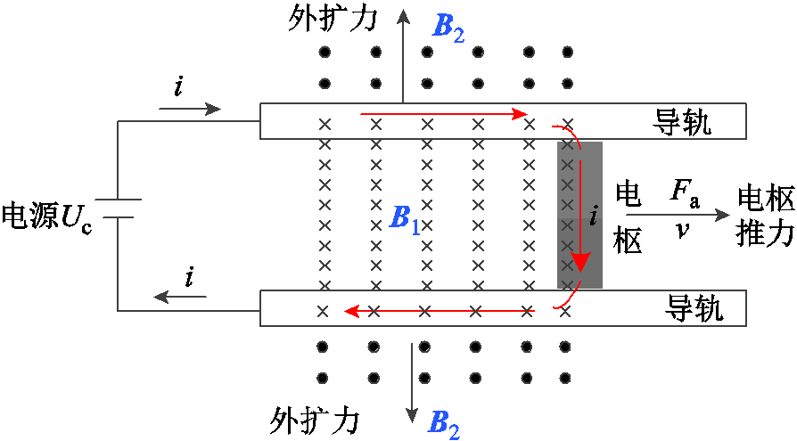
图1 电磁轨道发射装置工作原理
Fig.1 Principle of EML system
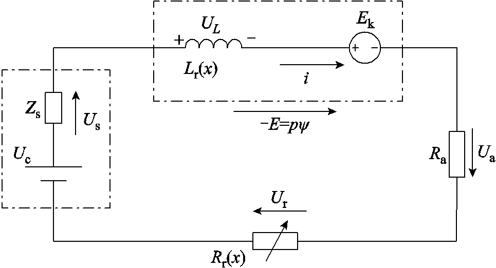
图2 发射装置串联电路原理图
Fig.2 Electrical series circuit of the EML
由于电枢在运动过程中,接入电气回路中的导轨电阻Rr和电感Lr不断增加,可见Rr和Lr随电枢位置x不断变化。则感应电动势E为
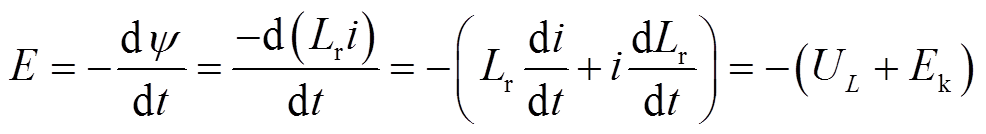 (1)
(1)
式中,UL为导轨电感电压;Ek为运动电动势。其可以分别表示为
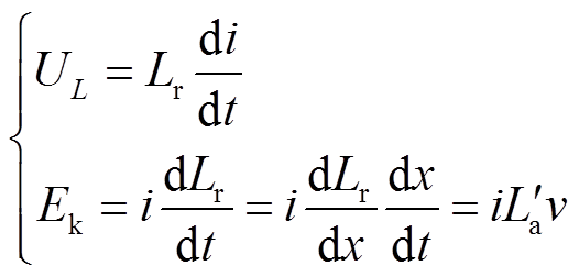 (2)
(2)
式中, 为电感梯度,定义为导轨电感Lr对电枢位移x的导数,即=dLr/dx;i为导轨电流;v为电枢速度。
设导轨电感Lr磁场储能为Wm,磁能随时间的变化率为
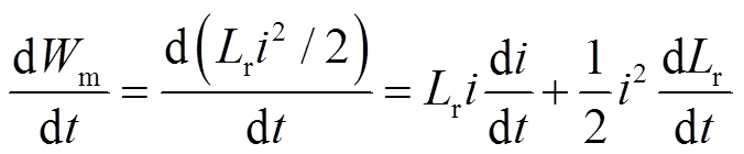 (3)
(3)
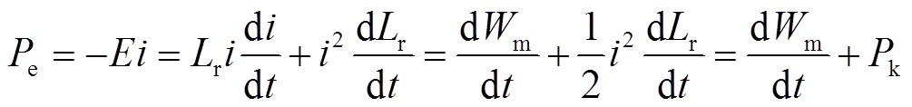
根据式(1)~式(3)可以得到感应电动势E吸收的电功率Pe为
 (4)
(4)
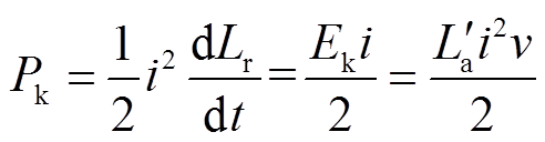
根据功率平衡原理,式(4)表明感应电动势E吸收的电功率一部分转换为磁能变化率dWm/dt,另一部分转换为电枢的机械功率Pk,且其值为运动电动势Ek吸收功率的一半,即
 (5)
(5)
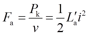
根据式(5)可以得到电枢电磁推力Fa为
 (6)
(6)
在电流i一定的条件下,电感梯度越大表明装置产生电枢推力的能力越强,这也是电感梯度是电磁轨道发射装置核心参数的主要原因[12]。将机械功率Pk用电阻消耗功率等效,定义动能电阻Rk,根据式(6)可以得到动能电阻Rk为
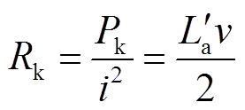 (7)
(7)
可见,动能电阻Rk除了与电感梯度成正比外,也与电枢速度成正比,即出口动能速度越高,动能电阻Rk越大。在串联电路中,Rk越大表示其耗能占比更高,系统效率更高。
导轨可以采用变化的电感Lr和电阻Rr表示,电枢电阻为Ra,采用脉冲电容C、晶闸管SCR、续流二极管VD以及调波电感器(Ls-Rs)构成的脉冲功率单元(Pulse Forming Unit, PFU)供电,能量效率是系统核心指标之一。由单个PFU供电的电磁发射装置等效电气原理图如图3所示,发射过程波形示意图如图4所示。
如图3、图4所示,Ts时刻为电枢出膛时刻。在[0, Ts]阶段,开关S闭合,电弧电阻Rh没有接入电路,此为电枢加速阶段;[Ts, Te]区间为电枢出膛阶段,开关S断开,电弧电阻Rh接入电路中。其中在[0, Tc]区间,电容能量经过晶闸管SCR放电,发射装置将电能转化为电枢动能,电容电压在Tc时刻降为零,晶闸管SCR电流过零关断;[Tc, Ts]区间,调波电感器经过续流二极管VD继续向装置输出能量,推动电枢运动直到出膛[13];[Ts, Te]区间为电枢出膛后拉弧阶段,电枢出膛后上下导轨被电弧短路,系统中剩余的电感储能被系统电阻和电弧电阻共同吸收[14-15]。
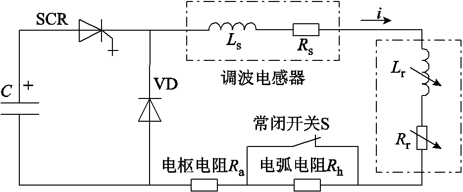
图3 发射装置原理电气原理图
Fig.3 Electrical circuit of the launcher system
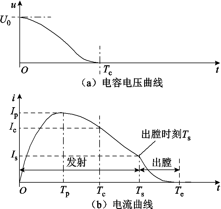
图4 发射过程波形示意图
Fig.4 Waveform of the transmission process
根据发射装置工作过程,可以得到电枢加速阶段和电枢出膛拉弧两个阶段的电路模型如图5所示。
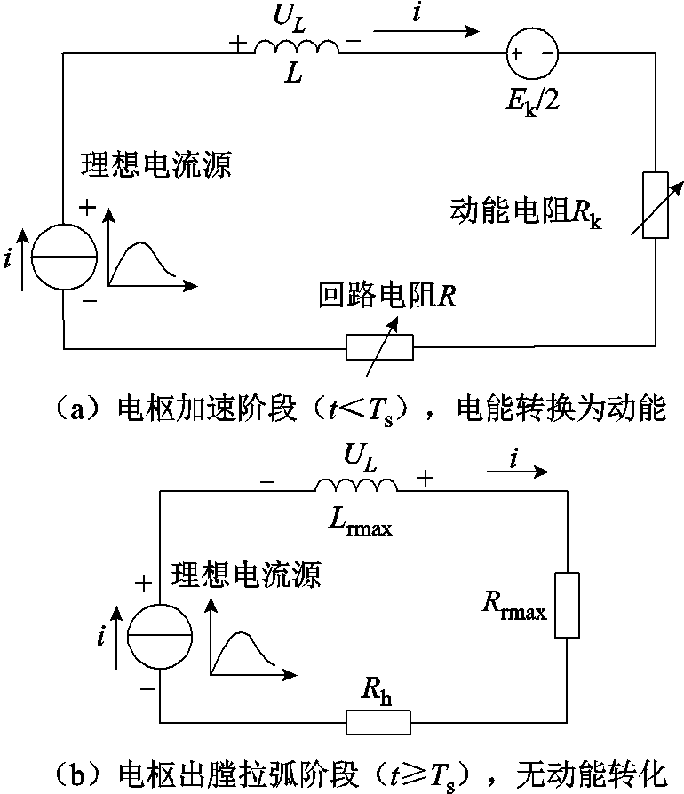
图5 分段工作电路模型
Fig.5 Electrical circuit model in different phases
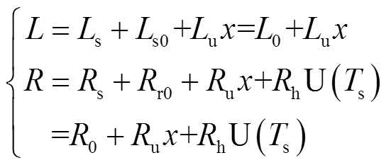
图5a为电枢加速阶段电路模型,电流源、回路电阻R、回路电感L、电动势Ek/2以及动能电阻Rk等串联,其中电流源电流按照图4b所示的电流曲线输出,电能转换为电枢动能。从图5b可以看出,当电枢出膛后电弧电阻Rh接入电路中,同时导轨电阻、电感均达到了最大值Rrmax和Lrmax,导轨电感不再随电枢位置x而变化,因此电感梯度=0,进而动能电阻Rk=0、电动势Ek/2=0,此时,系统无动能转化过程,系统剩余电感储能被导轨电阻Rrmax和电弧电阻Rh消耗。回路电感L、回路电阻R计算公式分别为
 (8)
(8)
式中,Rr0、Ls0分别为电枢初始位置对应的导轨电阻值和电感值;R0为系统杂散电阻;L0为系统杂散电感;Rs和Ls为调波电感器参数;电阻系数Ru和电感系数Lu为导轨单位长度的电阻值和电感值;U(·)为单位阶跃函数。
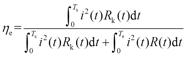
根据图5,可以得到系统能量效率ηe表达式为
 (9)
(9)
根据积分中值定理,闭区间连续函数的积分可表示为该区间某函数值与区间长度的乘积,所以有
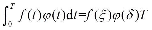 (10)
(10)
对式(9)进行化简,得到
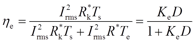 (11)
(11)
式中,Irms为[0, Te]区间内输入电流的有效值; 为能量等效电阻,其消耗的能量表示电枢出口动能;R*为损耗等效电阻,其消耗的能量表示系统损耗;参数Ke=
 ;D为电流等效占空比,D=Ts/Te。
根据式(9)、式(11),能量等效电阻 和损耗等效电阻R*可以分别表示为
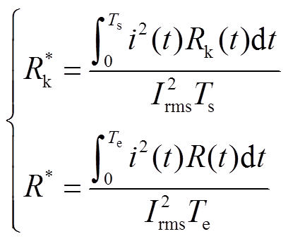 (12)
(12)
为了直观地分析系统能量效率影响因素,在图5所示电路模型基础上,根据能量等效原则和式(11),建立直流脉冲等效电路模型如图6所示。
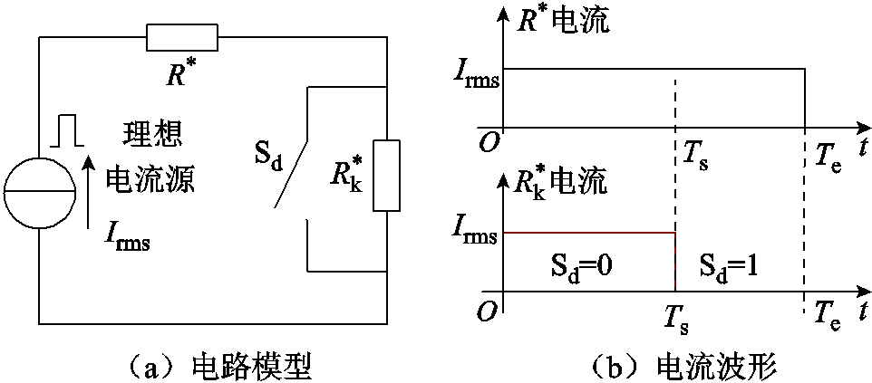
图6 直流脉冲等效电路模型
Fig.6 DC pulse equivalent circuit
图6a中的理想电流源为脉冲直流电源,在[0, Te]内幅值恒为Irms。在[0, Ts]区间内,开关Sd断开(Sd=0),接入电路中,电枢在膛内加速;在[Ts,Te]区间内,开关Sd闭合(Sd=1),短路,表示电枢出膛后无机械能的转换。从电阻消耗能量的物理原理可知,参数Ke反映了动能功率与损耗功率的比例关系,而参数D为动能转化时长Ts与系统时长Te之间的比例。
从图6所示的直流等效电路可知,当D=0(Ts=0)时,即开关Sd一直为闭合状态(Sd=1),类似于电枢堵转且无机械动能输出,称为电枢堵转模式,此时系统能量效率ηe=0;当D=1(Ts=Te)时,开关Sd一直为断开状态(Sd=0),电枢一直处于加速状态直到出膛,且出膛时刻Ts时电流为零,系统剩余磁场储能为零,类似于出口零电流模式。
式(11)表明系统能量效率ηe与占空比D和Ke的乘积呈正相关关系,令效率因子Kη=KeD,其表达式为
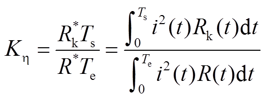 (13)
(13)
在电感梯度典型值为0.5 μH/m,以及最大速度为2 km/s的工况下,根据式(7)可知,式(13)分子中Rk(t)的最大值为0.5 mΩ,而实际系统中调波电感电阻、传输电缆电阻及导轨电阻之和往往远超过0.5 mΩ,因此Rk(t)≤R(t)且Ts≤Te,可见实际系统的效率因子Kη≤1。式(11)所表示的系统能量效率ηe与效率因子Kη的关系如图7所示。
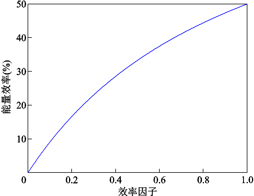
图7 能量效率ηe与效率因子Kη曲线
Fig.7 Energy efficiency ηecurve with Kη
从图7可知,系统能量效率ηe≤50%。分析可知,在不考虑系统损耗且恒流供电的理想工况下,系统效率因子Kη=1,能量效率ηe=50%[9]。由于实际发射装置存在杂散电阻、杂散电感以及出口电流不为零的工况,因此其能量效率不会超过50%。
受电流扩散和速度趋肤效应的影响,运动过程中,导轨电感系数Lu、电阻系数Ru和电感梯度是时变参数,为了准确地得到这些参数的动态变化过程,需要采用有限元仿真进行参数提取[16-17]。
电枢在膛内运动过程中,由于电枢速度影响新接入导轨中电流的扩散时间,因此导轨电流扩散深度同样受到电枢速度v的影响,这种与电枢速度相关的趋肤效应称为速度趋肤效应。由于电流频率会使导轨电流产生趋肤效应,根据趋肤深度等效原则,电枢以速度v运动时产生的趋肤效应,可以用电枢静止时的正弦激励工况进行等效,此时的频率fv称为速度频率。根据参考文献[18-19],速度频率fv计算式为
 (14)
(14)
式中,λ为电枢与导轨接触面的长度,即电枢长度。可见电枢速度v越大,对应的速度频率fv越大。
根据式(14)及其物理含义可知,引入速度频率fv后,可以将电枢运动过程转换为静止扫频等效模型(即通过涡流场扫频提取参数与频率的函数关系的三维静态仿真模型),可以大大降低运动模型的分析和求解难度。可见速度频率成为了动态运动模型和静态扫频模型之间的桥梁,三者之间的逻辑关系和数据交互关系如图8所示。
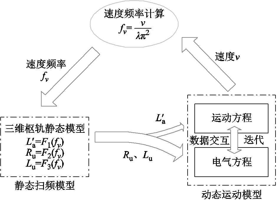
图8 速度频率与静态扫频模型、动态运动模型关系
Fig.8 Relationship between velocity frequency and static sweep model、dynamic motion model
从图8可知,首先利用Ansys有限元仿真软件对静态扫频模型进行有限频率点的涡流场扫频分析,并利用插值法获得相应的电磁参数(如Lu、Ru和)随频率f变化的函数;其次,在全系统动态仿真中,根据当前的输入电气量,结合运动方程获得电枢速度v,根据式(14)计算速度频率fv,并代入第一步的函数关系中,获得相应的电磁参数后;然后,将获得的电磁参数代入电气方程中以计算更新下个步长的电气量,并将其再次代入到运动方程中;如此循环迭代即可得到电枢运行的动态过程。

设定轨道厚度w=10 mm,轨道高度h=15 mm,轨道间距s=20 mm;电枢静止不动,电枢壁厚度 d=4 mm,电枢长度λ=30 mm,电枢喉部半径r=1 mm,电枢尾部距导轨尾部距离x=100 mm。装置的三维模型如图9所示。采用Ansys软件的三维涡流场对电枢静止不动的模型进行扫频分析,以获得相应的电磁参数,即静止扫频模型。结合输入电流基波频率(约为250 Hz)和速度频率(最高为10 kHz),涡流场扫描频率范围为100 Hz~10 kHz,电流峰值为100 kA,有效值为70.7 kA,仿真的空气域采用磁场强度切向分量恒为零(zero tangential H field)的边界条件。同时,考虑到10 kHz高频条件下的电流趋肤深度为0.75 mm左右,为了准确地仿真出电流趋肤效应和邻近效应,仿真模型中的四面体网格最大边长不大于0.5 mm。
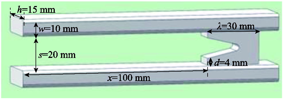
图9 装置三维模型结构
Fig.9 The 3D structure of the launcher
电流频率为500 Hz和10 kHz情况下的导轨电流密度分布仿真结果如图10所示。从图10可以看出,由于趋肤效应和邻近效应,电流主要分布在导轨四个边和电枢C形喉部区域,且更集中在导轨内侧。频率越高,电流越趋于导轨表面,同时也更集中在导轨内表面。电流密度在导轨中的分布影响了导轨电阻数值,同时也影响了导轨电感值。
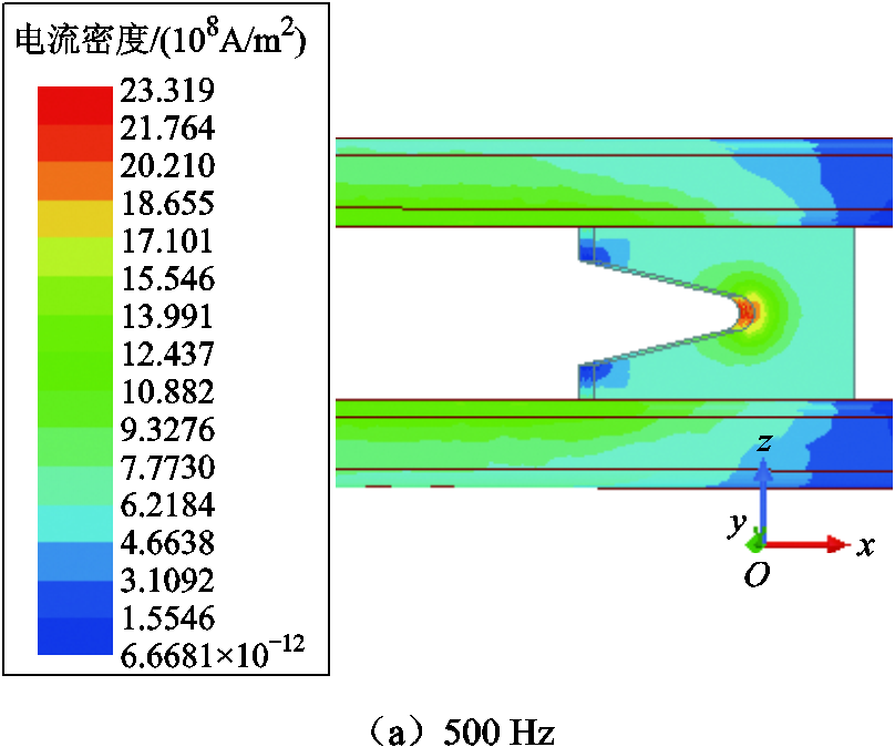
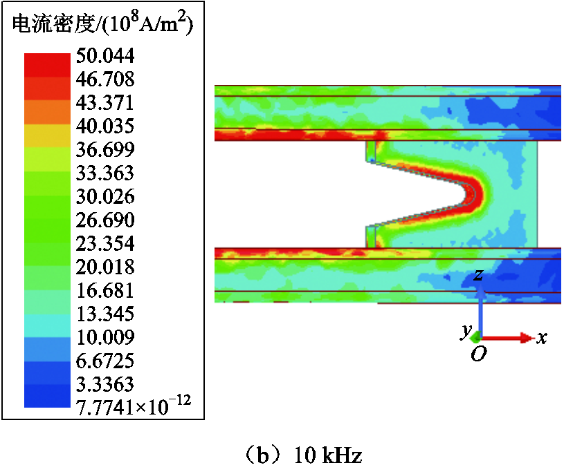
图10 涡流场电流密度分布
Fig.10 Eddy current density distribution
在三维涡流场仿真模型中可以获得不同频率下的回路电阻R和回路电感L,相应的数值除以电枢位置x就可以计算出Ru和Lu,同时通过电枢推力Fa和电流i可以反推出电感梯度,这些参数均随频率变化而变化。三维涡流场仿真和计算数据汇总见表1,图11给出了有限元模型获得的Ru、Lu、电枢推力Fa和电感梯度随频率f的变化曲线。
表1 三维涡流场仿真和计算数据汇总表
Tab.1 Summary table of simulation calculation data
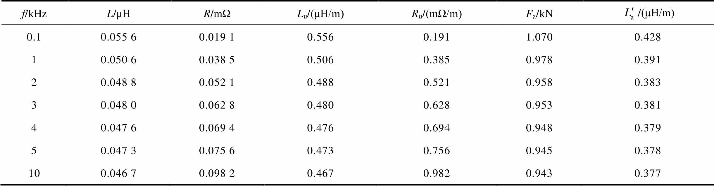
f/kHzL/μHR/mΩLu/(μH/m)Ru/(mΩ/m)Fa/kN/(μH/m) 0.10.055 60.019 10.5560.1911.0700.428 10.050 60.038 50.5060.3850.9780.391 20.048 80.052 10.4880.5210.9580.383 30.048 00.062 80.4800.6280.9530.381 40.047 60.069 40.4760.6940.9480.379 50.047 30.075 60.4730.7560.9450.378 100.046 70.098 20.4670.9820.9430.377
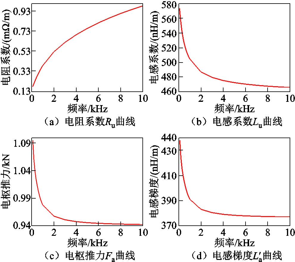
图11 Ru、Lu、Fa和 随频率f变化曲线
Fig.11 Curves of Ru, Lu, Fa and with frequency f
随着频率f增加,趋肤深度减小,导轨等效导流面积减小,等效电阻增大,同时电流回路面积不断减小而引起等效电感减小,因此出现电感系数Lu随着频率f不断减小,而电阻系数Ru随着频率f不断增加的变化趋势。同理,由于频率引起的趋肤效应,推力Fa和电感梯度均随着频率f增加而不断减小。
结合单个PFU供电的电气系统和运动方程,根据图8中所示各模型之间的逻辑关系,建立系统仿真框图如图12所示。

图12 系统电气仿真模型框图
Fig.12 Block diagram of simulation system
在图12中,可变电感L为回路总电感,包括杂散电感L0(同轴电缆、调波电感等固定电感)以及随电枢位置x变化的导轨电感Lr。可变电阻R为回路总电阻,包括杂散电阻R0(同轴电缆电阻、调波电感电阻、电枢电阻及出膛后的电弧电阻)以及随电枢位置x变化的导轨电阻Rr。仿真系统中使用插值拟合方法,获得了静态扫频模型中参数Lu和Ru及电感梯度随频率f变化的函数关系。参数Lu和Ru用于导轨电感Lr和电阻Rr的计算,而电感梯度用于电枢推力Fa的计算[20-21]。发射装置实物照片如图13所示,图14给出了一次发射过程的仿真和试验对比波形。
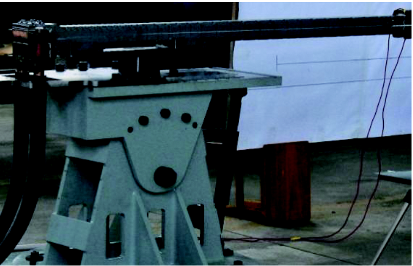
图13 发射装置实物
Fig.13 Photograph of the launcher
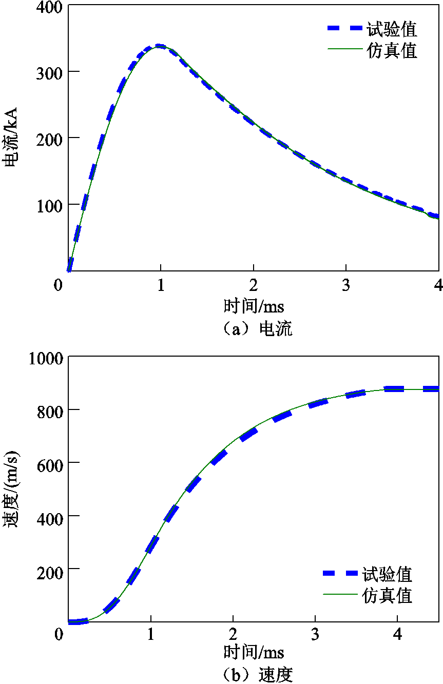
图14 仿真和试验数据对比
Fig.14 Comparison of simulation and test data
储能电容为240 mF,初始电压为DC1 200 V,总储能为172.8 kJ,试验电枢质量m为57.56 g。试验电流峰值为338.7 kA,仿真电流峰值为334.1 kA,仿真和试验的电流峰值误差为1.37%;试验出口速度为877.6 m/s,仿真出口速度为868.8 m/s,两者误差为1.01%;试验出口动能22.16 kJ,试验的能量效率为12.82%,仿真出口动能为21.72 kJ,对应的系统效率为12.57%,与试验得到的能量效率误差为-1.95%,而根据直流脉冲等效电路模型得到系统能量效率为13.04%,与试验能量效率误差为2.57%,可见仿真计算与试验误差在3%以内。直流脉冲等效电路模型具体数据见表2。
表2 直流脉冲等效电路模型中具体数据
Tab.2 Parameters of DC pulse equivalent circuit
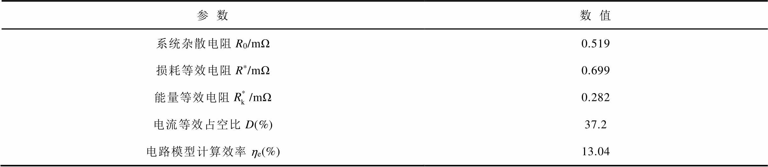
参数数值 系统杂散电阻R0/mΩ0.519 损耗等效电阻R*/mΩ0.699 能量等效电阻/mΩ0.282 电流等效占空比D(%)37.2 电路模型计算效率ηe(%)13.04
根据表2可知,能量等效电阻 仅为系统损耗等效电阻R*的40.3%(即Ke=0.403),同时电流波形等效占空比D较小,仅为37.2%,可见系统损耗远大于转换的动能,系统效率较低。由于导轨截面较小,加上趋肤效应对导轨电阻和调波电感电阻的影响,系统杂散电阻R0=0.519 mΩ,占到损耗等效电阻R*(0.699 mΩ)的74.3%,可见杂散电阻R0过大引起R*过大,即引起系统损耗过大,从而导致装置效率较低。
导轨电阻是系统欧姆损耗的一部分,其导电特性对系统效率有着直接的影响,是装置效率性能优化的重点因素之一。导轨采用三种不同电导率铜材料(黄铜(30%IACS)、铬镐铜(45%IACS)、纯铜(90%IACS),IACS为国际退火铜标准,在此标准下,标准退火纯铜的电导率为100%IACS),在电容初始电压为DC 1 500 V的条件下,利用系统建立的仿真模型,得到出口速度及能量效率的仿真结果对比如图15所示。
从图15所示的仿真结果对比可以看出,随着导轨电导率的提高,回路电阻会降低、输入电流会增加,出现了电枢出口速度和系统效率增加的结果。主要原因包括两个方面:一方面增加导轨电导率会降低系统损耗电阻等效R*;另一方面出口速度增加提高了系统能量等效电阻。从直流脉冲等效电路模型可以看出,这两方面均有利于系统效率增加,可见仿真与电路模型分析结论是一致的。
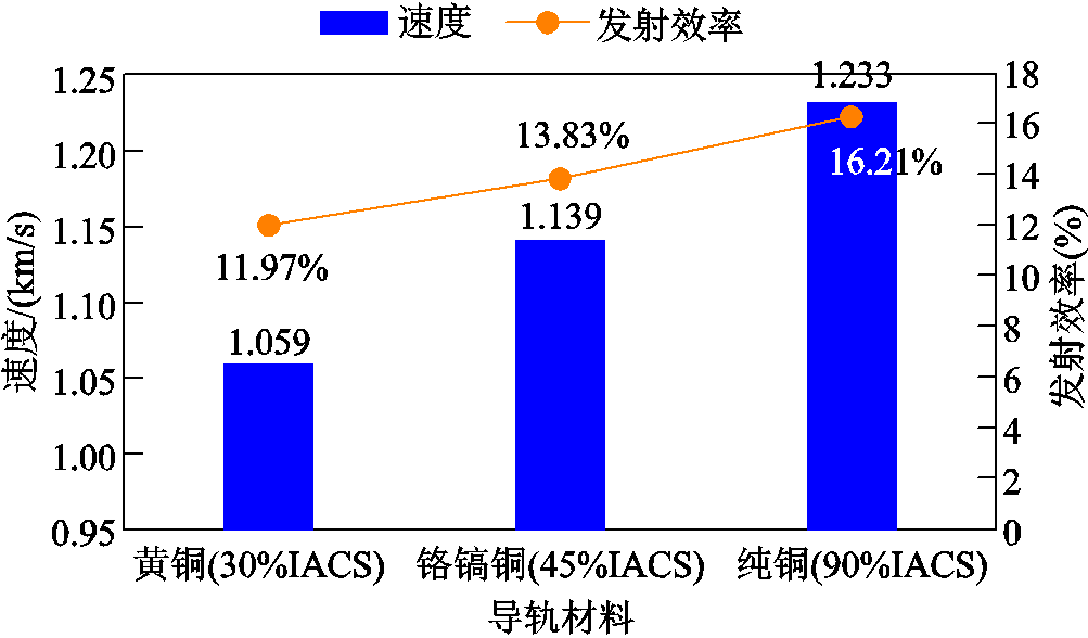
图15 不同电导率导轨的仿真性能对比
Fig.15 Comparison of simulation performance with different conductivity rails
本文提出了直流脉冲等效电路模型和系统效率分析方法以及全系统电气仿真模型,仿真计算与试验数据相比误差小于3%,证明了文中所提等效模型及效率分析方法的准确性,为电磁轨道发射系统的效率优化设计提供了重要的分析方法。
从直流脉冲等效电路模型及其参数计算公式可知,从增加系统能量等效电阻和减小系统损耗等效电阻R*两个方面,可获得一些效率优化设计的措施和方法。
1)优化设计导轨截面形状和空间尺寸,以提高电感梯度,并在满足导轨强度前提下选择高电导率的合金铜材料从而减小导轨损耗。
2)减小供电电缆长度[22],尽可能地增加电缆和调波电感器的有效通流面积,减小器件的欧姆损耗。
3)通过多个PFU联合供电,优化放电时序实现对电流波形调节,减小出口电流可以减小系统剩余磁场能量,从而提高系统效率。
参考文献
[1] 王莹, 肖峰. 电炮原理[M]. 北京: 国防工业出版社, 1995.
[2] 马伟明, 鲁军勇, 李湘平. 电磁发射超高速一体化弹丸[J]. 国防科技大学学报, 2019, 41(4): 1-10. Ma Weiming, Lu Junyong, Li Xiangping. Electromagnetic launch hypervelocity integrated projectile[J]. Journal of National University of Defense Technology, 2019, 41(4): 1-10.
[3] Ma Weiming, Lu Junyong, Liu Yingquan. Research progress of electromagnetic launch technology[J]. IEEE Transactions on Plasma Science, 2019, 47(5): 2197-2205.
[4] 彭之然, 刘华, 汪光森, 等. 基于多模块分时放电半解析模型的脉冲电源触发策略[J]. 电工技术学报, 2021, 36(增刊1): 54-61. Peng Zhiran, Liu Hua, Wang Guangsen, et al. Trigger strategy of pulsed power supply based on the semi-analytical model of sequentially-triggered power units[J]. Transactions of China Electrotechnical Society, 2021, 36(S1): 54-61.
[5] 马伟明. 关于电工学科前沿技术发展的若干思考[J].电工技术学报, 2021, 36(22): 4627-4636. Ma Weiming. Thoughts on the development of frontier technology in electrical engineering[J]. Transactions of China Electrotechnical Society, 2021, 36(22): 4627-4636.
[6] Li Chengxian, Chen Lixue, Wang Zengji, et al. Influence of armature movement velocity on the magnetic field distribution and current density distribution in railgun[J]. IEEE Transactions on Plasma Science, 2020, 48(6): 2308-2315.
[7] 刘旭堃, 于歆杰, 刘秀成. 电容储能型脉冲电源分时分段触发策略自动计算方法[J]. 电工技术学报, 2016, 31(11): 186-193. Liu Xukun, Yu Xinjie, Liu Xiucheng. An automatic calculation method for the triggering strategy of the capacitive pulsed-power supply[J]. Transactions of China Electrotechnical Society, 2016, 31(11): 186-193.
[8] Engel T G, Neri J M, Nunnally W C. Efficiency and scaling of constant inductance gradient DC electromagnetic launchers[J]. IEEE Transactions on Magnetics, 2006, 42(8): 2043-2051.
[9] Engel T G. The high-efficiency mode of electrom-agnetic launcher operation[J]. IEEE Transactions on Plasma Science, 2020, 48(4): 1106-1110.
[10] Engel T G, Neri J M, Veracka M J. Characterization of the velocity skin effect in the surface layer of a railgun sliding contact[J]. IEEE Transactions on Magnetics, 2008, 44(7): 1837-1844.
[11] 刘旭堃, 于歆杰, 刘秀成, 等. 电磁轨道炮运行阶段系统发射效率和电枢出膛动能研究[J]. 电工技术学报, 2017, 32(3): 210-217. Liu Xukun, Yu Xinjie, Liu Xiucheng, et al. Researches on the system launch efficiency and the armature muzzle kinetic energy of a constructed electromagnetic railgun[J]. Transactions of China Electrotechnical Society, 2017, 32(3): 210-217.
[12] 彭之然, 汪光森, 翟小飞, 等. 电磁轨道发射装置时变电感梯度建模与分析[J]. 电工技术学报, 2020, 35(23): 4843-4851. Peng Zhiran, Wang Guangsen, Zhai Xiaofei, et al. Modeling and analysis of time-varying inductance gradient for electromagnetic rail launcher[J]. Transactions of China Electrotechnical Society, 2020, 35(23): 4843-4851.
[13] Yang Fan, Zhai Xiaofei, Zhao Zhihua, et al. Research on the armature–rail dynamic contact characteristics of the series enhanced electromagnetic rail launcher[J]. IEEE Transactions on Plasma Science, 2022, 50(4): 1040-1047.
[14] Sun Jian, Cheng Junsheng, Wang Qiuliang, et al. Research on arc suppression parameter matching of augmented electromagnetic launcher[J]. IEEE Transactions on Plasma Science, 2021, 49(12): 3988-3993.
[15] 李湘平, 鲁军勇, 张晓, 等. 电磁发射弹丸膛口磁场分布特性分析[J]. 电工技术学报, 2021, 36(3): 525-531. Li Xiangping, Lu Junyong, Zhang Xiao, et al. Analysis of distribution characteristics of electromagnetic launcher projectile muzzle magnetic field[J]. Transactions of China Electrotechnical Society, 2021, 36(3): 525-531.
[16] Tosun N, Ceylan D, Polat H, et al. A comparison of velocity skin effect modeling with 2-D transient and 3-D quasi-transient finite element methods[J]. IEEE Transactions on Plasma Science, 2021, 49(4): 1500-1507.
[17] An S, Lee B, Bae Y, et al. Numerical analysis on the transient inductance gradient of the resistive overlay rail on the sliding electrical contact[J]. IEEE Transactions on Plasma Science, 2019, 47(5): 2339-2342.
[18] Lü Qingao, Xiang Hongjun, Lei Bin, et al. Physical principle and relevant restraining methods about velocity skin effect[J]. IEEE Transactions on Plasma Science, 2015, 43(5): 1523-1530.
[19] 翟小飞, 李鑫航, 刘华, 等. 电磁轨道发射装置动态电感梯度分析[J]. 国防科技大学学报, 2022, 44(3): 156-163. Zhai Xiaofei, Li Xinhang, Liu Hua, et al. Analysis of dynamic inductance gradient of electromagnetic rail launcher[J]. Journal of National University of Defense Technology, 2022, 44(3): 156-163.
[20] An S, Lee B, Bae Y, et al. Numerical analysis of the transient inductance gradient of electromagnetic launcher using 2-D and 3-D finite-element methods[J]. IEEE Transactions on Plasma Science, 2017, 45(7): 1635-1638.
[21] Zhai Xiaofei, Liu Hua, Peng Zhiran. Research on armature thrust inductance gradient of the electromagnetic rail launcher[J]. IEEE Transactions on Plasma Science, 2022, 50(3): 754-760.
[22] Vaskovskyi Y M, Raichev P O. Improvement of the energy efficiency of the railgun[C]//2019 IEEE 2nd Ukraine Conference on Electrical and Computer Engineering (UKRCON), Lviv, Ukraine, 2019: 261-264.
Abstract The electromagnetic rail launch system was mainly composed of a pulse power supply and a launch device. It was limited by the saturation of the magnetic material, the low conductivity of the rail, the current skin effect and proximity effect. So, the inductance gradient of the device was low and the resistance gradient of the rail was high, resulting in low launch efficiency of the system. The system also had the characteristics of time-varying parameters, multi-field coupling, and short-duration pulse operation, so it was difficult to carry out accurate dynamic simulation calculation of the whole system. In order to improve the launch efficiency of the device, this paper established an equivalent circuit model of the system including the pulse power supply and the launch device, and given the extraction method of dynamic parameters, and analyzed the factors affecting the launch efficiency.
Firstly, the concept of kinetic energy resistance Rk was introduced through theoretical derivation, and the kinetic energy of the armature was converted into resistance loss. According to the working characteristics in the launching process, the circuit model of two working stages of armature acceleration and armature arcing at the time of exiting the bore was established. Secondly, based on the series circuit model, according to the energy equivalent principle, a mathematical model of the system energy efficiency ηe, energy equivalent resistance , loss equivalent resistance R* and current equivalent duty cycle D was established. According to the mathematical model, a DC pulse equivalent circuit model was established. In addition, considering the change of the barrel parameters during the armature movement, the velocity equivalent frequency was introduced, and using finite element simulation software to perform frequency sweep analysis of eddy current field to convert armature motion model into static frequency sweep model. Then, the curves of the rail inductance Lu, the resistivity Ru and the inductance gradient  as a function of frequency were obtained. The whole system electrical simulation model was established for simulation analysis, and the theoretical model, simulation model and experiment were compared, the results showed that the error between the three launch efficiency was less than 3%. Finally, the factors affecting the efficiency of the single launch experiment was analyzed, and it showed that the energy equivalent resistance was too small and the loss equivalent resistance R* was too large, which was the main reason for the low launch efficiency of the device: One was that due to the low gradient of the system inductance, the energy equivalent resistance was only 40.3% of the system loss resistance R*. In addition, the inherent loss of the system other than the loss of the rails accounted for 74.3% of the loss equivalent resistance R*. At the same time, the excessive outlet current leaded to a large residual magnetic field energy of the system, which further aggravated the additional energy consumption of the system. The design direction of launch efficiency optimization was given: increasing the inductance gradient, reducing the system loss resistance, and reducing the outlet current to reduce the residual magnetic field energy.
The DC pulse equivalent circuit model was established by introducing the concept of kinetic energy resistance and the energy equivalence principle. The simulation model of the whole system was established after extracting time-varying parameters from the finite element model. The equivalent circuit model, system simulation and test results are compared and analyzed to verify the correctness and effectiveness of the equivalent circuit and simulation system. Finally, it provides a research method for the efficiency analysis and optimal design of electromagnetic launcher system.
Keywords:Electromagnetic rail launch, launch efficiency, equivalent circuit model, dynamic parameter, simulation system
DOI:10.19595/j.cnki.1000-6753.tces.220328
中图分类号:TM153.2
国家自然科学基金(92266104)和军科委卓越青年科学基金(2021-JCJQ-ZQ-004)资助项目。
收稿日期 2022-03-08
改稿日期 2022-08-25
翟小飞 男,1982年生,博士,副研究员,硕士生导师,研究方向为电磁发射技术。Email:smartnavy@126.com
刘 华 男,1987年生,博士,助理研究员,研究方向为电磁发射技术。Email:627386936@qq.com(通信作者)
(编辑 李冰)