 (1)
(1)
摘要 非晶合金用于电机铁心可极大地提高电机效率,然而,其较大的磁致伸缩系数和极强的应力敏感性(即磁致伸缩逆效应)在增大铁心振动噪声的同时,限制电信号对铁心磁性能的精确控制能力。该文提出采用磁致伸缩逆效应对铁心磁化状态进行调制,以抑制非晶合金开关磁阻电机电磁振动的减振思路。首先,基于宏观热力学理论,建立考虑磁致伸缩及其逆效应的非晶合金材料力-磁耦合本构关系;其次,提出非晶合金开关磁阻电机的定子齿加压结构,并考虑静态预应力、脉动电磁应力对非晶合金磁特性的影响,构建开关磁阻电机力-磁双向动态耦合模型并求解;最后,计算应力作用前后定子铁心的磁通密度分布。通过实验与仿真对比发现,定子齿加压结构的径向电磁应力可减小44.5 %,因此该减振方法具有可行性。
关键词:磁致伸缩逆效应 磁致伸缩效应 电磁振动 开关磁阻电机减振方法 非晶合金
开关磁阻电机具有结构简单、起动转矩大、调速范围宽、成本低等优势,近年来在新能源电动汽车、航天和机械制造等领域得到了广泛应用。然而,由于开关磁阻电机的双凸极结构和开关性的供电电源,使得传统开关磁阻电机的效率较低且振动和噪声较高,这限制了其进一步的推广应用[1-2]。
非晶合金作为一种新型的导磁材料,具有高磁导率、低矫顽力、高饱和磁通密度、低损耗等特 点[3]。铁基非晶合金替代传统硅钢应用于电机铁心,可显著降低铁心的损耗和温升,在电机设计领域具有良好的应用前景[4-5]。然而,非晶合金相较于硅钢材料有着较大的磁致伸缩系数和应力敏感性,增大铁心电磁振动噪声的同时,限制电信号对铁心磁性能的精确控制能力,成为限制非晶合金开关磁阻电机广泛应用的瓶颈[6]。
非晶合金开关磁阻电机(Switched Reluctance Motor with amorphous Alloy cores, SRMA)电磁噪声的主要来源为切向电磁力引起的转矩脉动和径向电磁力引起的振动。目前,抑制转矩脉动和降低电磁振动的方法分别为控制策略和电机本体结构的优化。转矩脉动的抑制方法为通过电压、电流及转矩控制策略,寻找最优控制参数,优化电流波形以达到抑制转矩脉动的效果[7-8]。转矩脉动控制策略算法较为复杂,驱动系统的成本较高。
结构优化多为设计新型定转子或绕组结构并优化其设计参数,以达到减小径向磁通、减小径向电磁力的目的。文献[9]提出在转子齿两侧开槽,通过改变转子表面磁通密度方向,削弱转子表面的径向磁通密度,减小电机的电磁振动;文献[10]通过比较在转子齿顶部位和齿根部位开孔时的转矩脉动,发现靠近齿顶开孔可以降低电机的转矩脉动;文献[11]提出转子极由嵌入铝转子中的分段硅钢组成梯形结构来减小径向电磁力。然而,上述减振方法均以材料的基本磁化曲线为数据基础,电机运行中脉动的激励会在铁心不同位置产生脉动电磁应力,铁心材料的磁化状态会随着脉动电磁应力发生动态变化(即磁致伸缩逆效应),其磁导率也会以应力为变量发生改变,而上述方法均未考虑脉动电磁应力和磁致伸缩力对材料磁导率的反向动态影响,这将限制减振设计的精确性。
在SRMA的减振方法中考虑非晶合金应力敏感性,其关键问题为建立非晶合金的力-磁耦合本构关系。目前,线性压磁方程是应用较广的计及磁致伸缩逆效应的材料本构关系方程。其中,应力引起的磁感应强度变化用压磁系数d(恒应力作用下)和应力s 的乘积ds 表示,线性压磁方程表述简单,适用于硅钢铁心材料建模,原因为硅钢铁心的外部夹件作用力可与定转子间产生的动态径向电磁力抵消,且硅钢应力敏感性差,应力引起的磁感应强度变化较小或近似为恒应力工况[12-16]。对于非晶合金材料本构关系,文献[17-18]基于线性压磁方程分析磁致伸缩对非晶合金铁心振动的影响,其在材料本构关系中忽略了外加应力项,即未对外加应力下的磁致伸缩逆效应进行模拟。然而,非晶合金应力敏感性强,压应力会使材料导磁能力下降,且下降值随应力的增加而增大[19-20],即压磁系数为非线性,因此线性压磁方程不适用于SRMA铁心的材料建模。
综上所述,解决SRMA减振结构设计精度问题的关键为:构建准确的考虑磁致伸缩及其逆效应的非晶合金材料力-磁耦合本构关系,并考虑应力对材料磁导率的非线性影响。首先,基于宏观热力学理论,建立考虑磁致伸缩及其逆效应的非晶合金非线性力-磁耦合本构关系,模型同时考虑了静态的外加应力和动态的电磁力、磁致伸缩力对材料磁导率的影响;其次,耦合非晶合金材料力-磁耦合本构关系与有限元方法,建立力-磁双向耦合模型,对本文提出的SRMA定子齿加压结构进行电磁振动仿真;最后,对比SRMA改进前后的电磁振动特性,结合实验测量结果验证了减振方法的可行性。
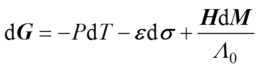
首先,基于宏观热力学理论,本文对非晶合金材料在应力作用下的应变进行分析。非晶合金材料单位体积内的Gibbs自由能G的全微分[20]可表示为
(1)
式中,P为熵密度;T为温度; 为应变;
为应变; 为应力;H为磁场强度;M为磁化强度;
 为空气磁导率
 的倒数,=4p×10-7 H/m。
当温度恒定时,非晶合金材料的应变可表示为
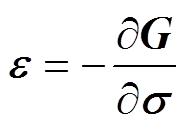 (2)
(2)
将Gibbs自由能表达式进行泰勒级数展开后,式(2)可表示为
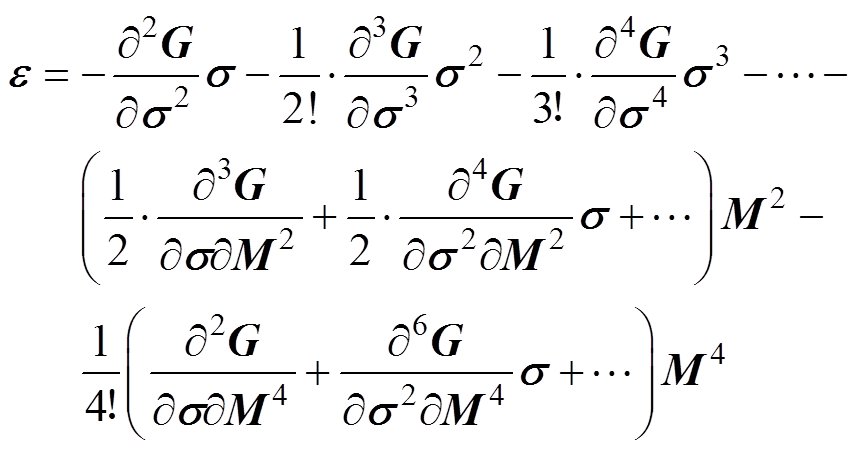 (3)
(3)
由式(3)可知,非晶合金在应力和磁场共同作用下产生的应变为应力和磁化强度的多项式,其中,与应力相关项为弹性应变,与磁化强度相关项为磁致伸缩应变。忽略高次项,并在磁化二次方项中引入应力和磁场强度H的磁通密度耦合项 ,则应力和磁场共同作用下,考虑磁致伸缩效应的非晶合金应变可简化为
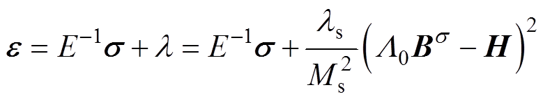 (4)
(4)
式中,E为非晶合金材料的杨氏模量,取120 GPa; 为磁致伸缩应变;
 为非晶合金材料的饱和磁致伸缩系数,取18 mm/m;Ms为非晶合金材料的饱和磁化强度。
其次,从能量角度分析材料的磁致伸缩逆效应并构建模型。磁致伸缩及其逆效应原理如图1所示。当非晶合金材料在磁场作用下,其长度会伸长或缩短,伸长或缩短量与原长度的比值即为磁致伸缩应变,如图1a和图1b所示。当非晶合金材料同时受到磁场和应力作用时,相比于磁场单独作用,一方面,应力的施加使磁致伸缩应变产生增量 ;另一方面,材料的磁特性发生改变,磁通密度由B变为,即磁场能量产生增量,如图1c所示。从能量角度分析,材料磁场能增量是由外加的应力能引起的,因此,材料的磁致伸缩逆效应即为应力能完全转化为磁场能的过程。
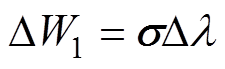
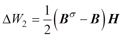
由于应力施加引起的材料磁致伸缩应变增量为,因此,单位体积内产生的应力能 可表示为磁致伸缩应变的增量与应力的乘积,即
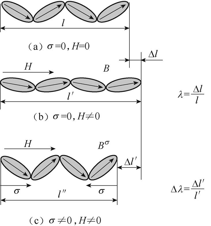
图1 磁致伸缩及其逆效应原理
Fig.1 Schematic of magnetostriction and inverse-magnetostriction effect
 (5)
(5)
将式(4)中的磁致伸缩应变表达式代入式(5),并化简得
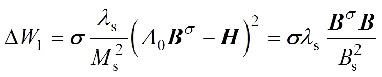 (6)
(6)
式中,Bs为饱和磁通密度。
材料单位体积的磁场能增量 可以表示为
可以表示为
 (7)
(7)
由于材料磁场能增量是由应力能提供的,即=,联立式(6)、式(7)得到应力下的磁通密度表达式为
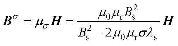 (8)
(8)
式中, 为应力下非晶合金材料的相对磁导率;
 为无应力作用下非晶合金材料的相对磁导率。其中,Bs、的数值本文通过实验测量。
综上所述,考虑磁致伸缩及其逆效应的非晶合金力-磁耦合本构关系表示为
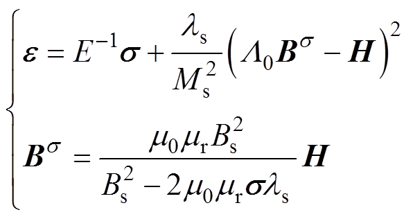 (9)
(9)
由于非晶合金材料的磁特性具有非线性和饱和性,需对特定型号的非晶合金进行磁特性测试。待测的非晶合金材料本构关系参数为相对磁导率和饱和磁通密度Bs,本文搭建非晶合金磁特性测量平台,如图2所示。平台以IEC 60404-2为标准,包括LabVIEW嵌入式软件的控制系统、NI-PXIe6124多功能数据采集系统、AE7224功率放大器、SR560信号调理模块及爱泼斯坦方圈。非晶合金样片为1K101铁基非晶合金,实验测得的磁化曲线及相对磁导率曲线如图3所示,根据测量结果,饱和磁通密度Bs取1.56 T。
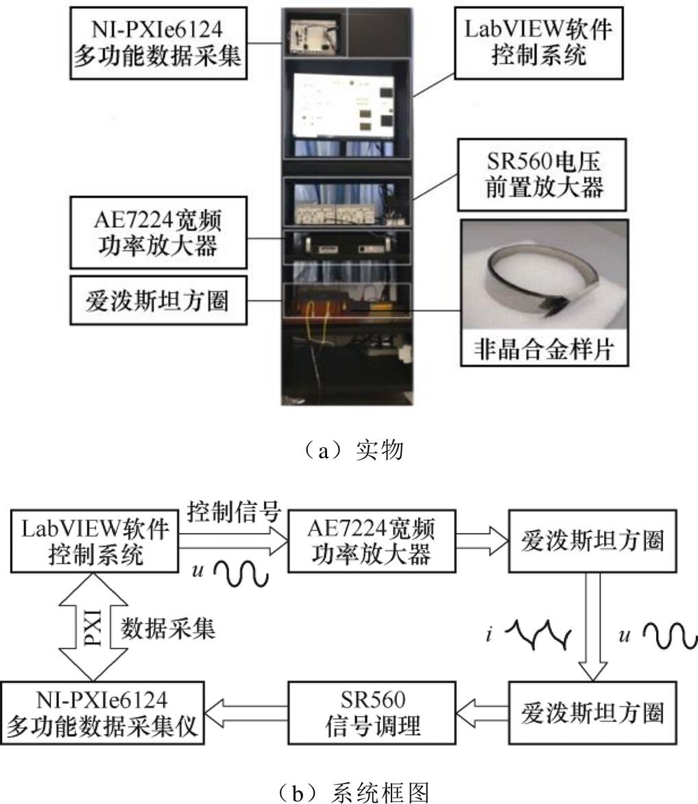
图2 磁特性测量系统
Fig.2 Magnetic properties measurement system
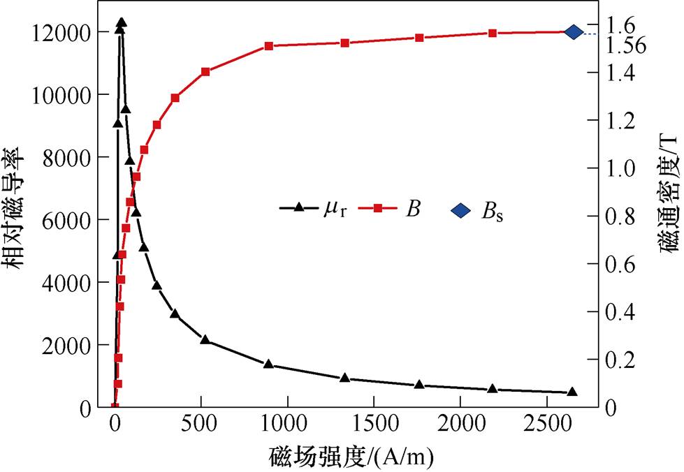
图3 1K101非晶合金磁化曲线
Fig.3 Magnetization curves of amorphous alloy 1K101
结合测量参数,对考虑磁致伸缩及其逆效应的非晶合金力-磁耦合本构关系进行模拟,得到磁致伸缩应变和相对磁导率曲线,如图4所示。可知,非晶合金材料的磁致伸缩应变和相对磁导率与外加磁场呈非线性关系,且应变和相对磁导率随着压应力的增加而逐渐减小。
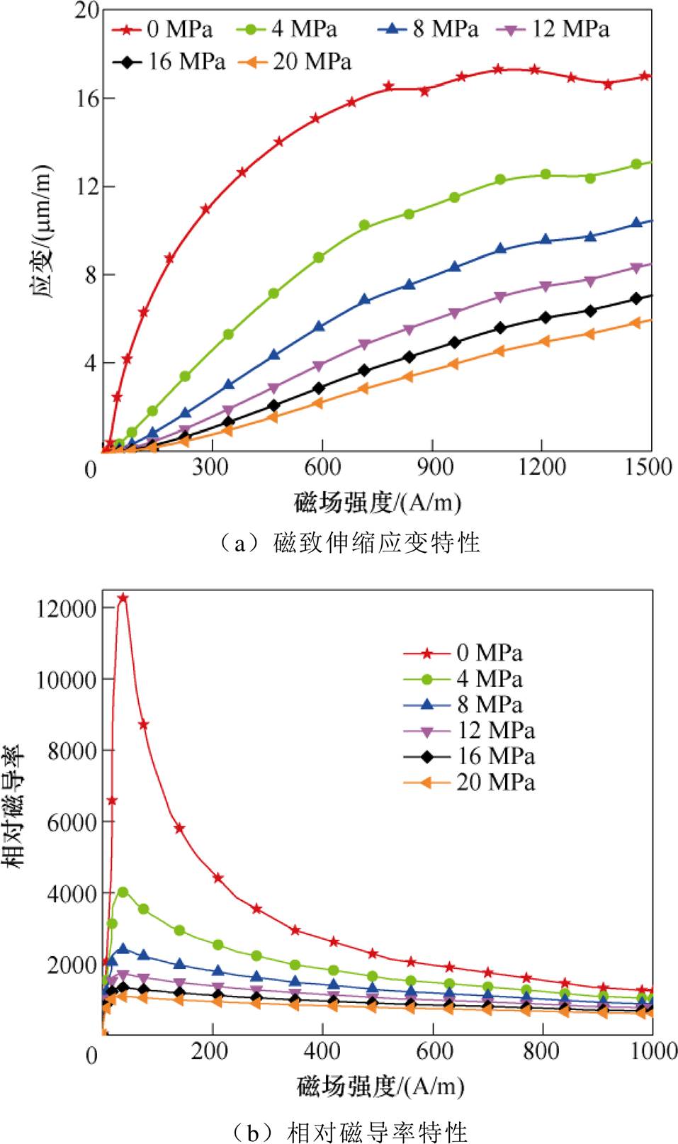
图4 不同应力下非晶合金磁致伸缩和相对磁导率特性
Fig.4 Characteristics of magnetostriction and relative permeability of amorphous alloys under different stresses
磁导率畸变特性如图5所示。根据模拟的磁特性曲线,若励磁磁场为正弦量,如图5c所示,则磁导率随时间变化波形如图5a所示,可知,在磁场强度的一个时间周期0~t3中,当H<H1时,磁场未达到饱和状态,磁导率在时间0~t1和t2~t3内与H成正比;当H>H1时磁场达到饱和状态,磁导率随着H的增大而减小,即在时间t1~t2内与H成反比。根据图5可知,压应力会使磁特性曲线下移,则磁导率也将下降,使材料磁化状态由饱和区到线性区,因此,可利用非晶合金材料的磁致伸缩逆效应,设计电机的定子减振结构。
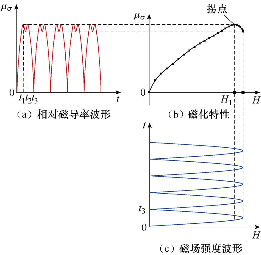
图5 磁导率畸变特性
Fig.5 The characteristic of permeability distortion
SRMA电磁振动的主要来源为定转子铁心间的径向电磁力,本文利用非晶合金的磁致伸缩逆效应,通过对定子铁心径向施加压应力,降低定子铁心的磁饱和程度,达到减小电磁振动的目的。据此,本文提出定子齿加压结构,采用螺栓给定子齿施加径向压应力,整体结构如图6所示。
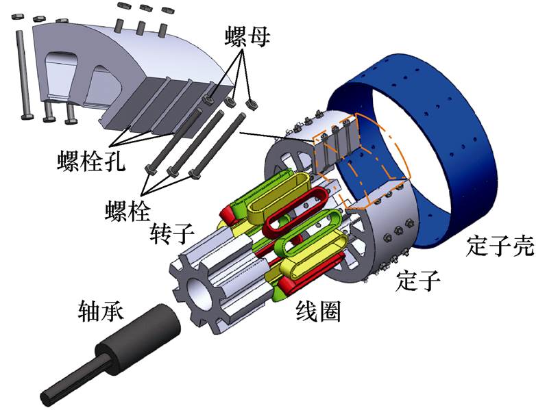
图6 SRMA定子加压结构
Fig.6 The compressive stress applied structure of SRMA stator
螺栓选材为45号钢,GB/T 699-2015标准规定其抗拉强度为600 MPa,屈服强度为355 MPa。螺栓在定子铁心的叠片方向上等距居中分布,一方面均匀分布的应力可以保证磁致伸缩逆效应对定子铁心的磁特性调制均匀,避免了因转子两端受力不均而对旋转平衡造成的破坏,且定子齿螺栓孔两侧的材料磁特性在静态压应力作用下可保持一致,使得电机在正反转时具有相同的动态特性,可满足实际应用中电机的正反转需求;另一方面,中间位置开孔时定子齿不会承受来自于螺栓的切向弯曲应力,保证了定子铁心的机械强度,在工业上具有更可靠的应用价值。
为了确定螺栓施加应力的范围,同时,保证螺栓结构不会影响电机定转子的齿槽配合,需对SRMA定子齿加压结构进行有限元结构分析。螺栓根数较少难以满足磁致伸缩逆效应下应力对定子铁心的磁特性调制要求,根数较多则大大增加了工艺难度。当只考虑由螺栓压应力产生的SRMA定子齿形变时,叠片方向上每个螺栓所在截面的形变分布相同,因此,本文建立了包含螺栓结构的二维SRMA有限元模型,在简化计算量的同时该模型也适用于不同螺栓数量的定子齿加压结构,SRMA二维有限元模型如图7所示,主要参数见表1。
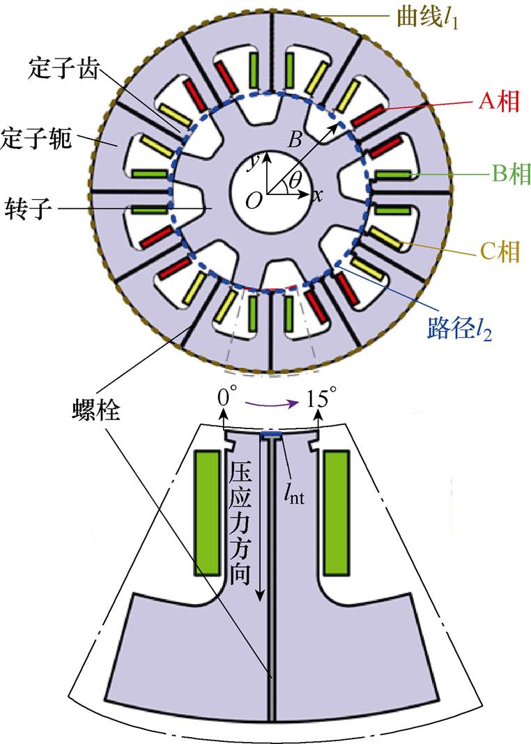
图7 SRMA二维有限元模型
Fig.7 Two-dimensional finite element model of SRMA
表1 SRMA电机参数
Tab.1 The parameters of SRMA
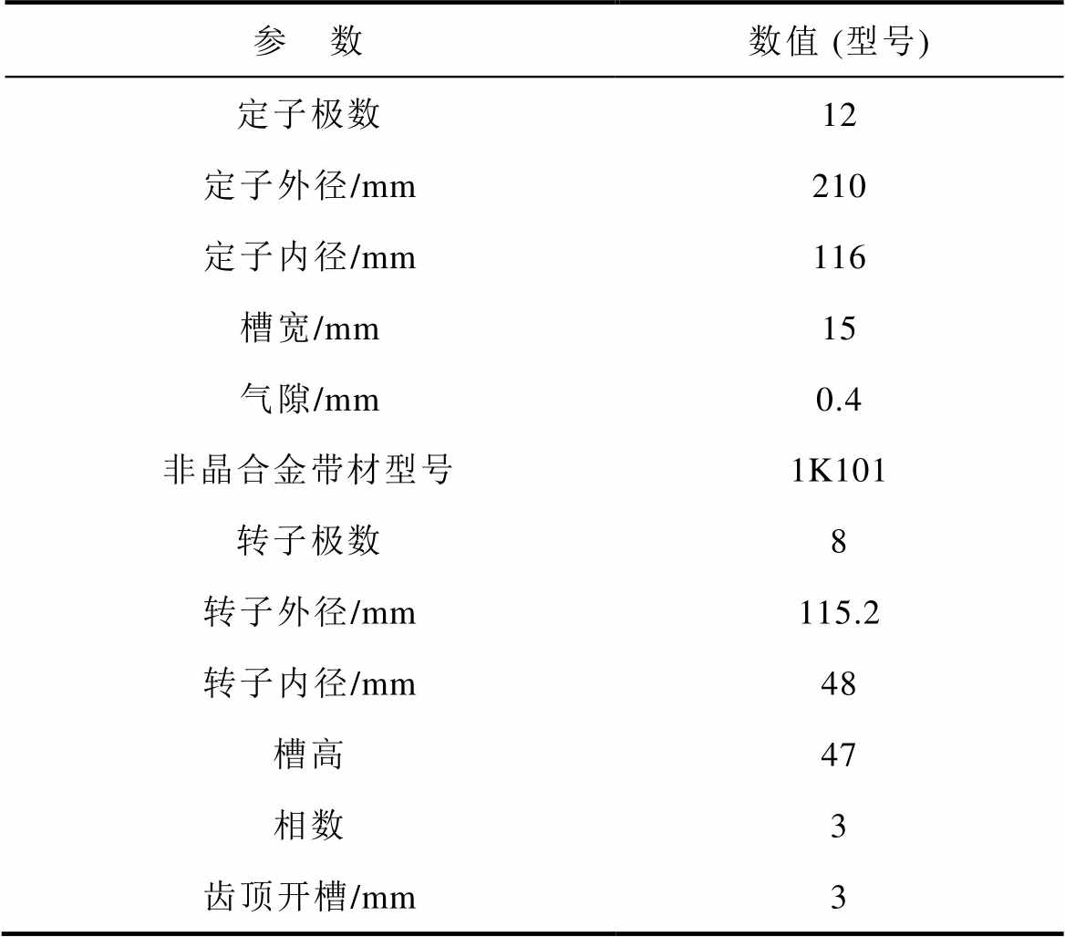
参 数数值 (型号) 定子极数12 定子外径/mm210 定子内径/mm116 槽宽/mm15 气隙/mm0.4 非晶合金带材型号1K101 转子极数8 转子外径/mm115.2 转子内径/mm48 槽高47 相数3 齿顶开槽/mm3
在有限元模型中,通过边界lnt施加垂直于边界的载荷,边界位置及应力方向如图7所示,则定子齿的形变 可以表示为
可以表示为
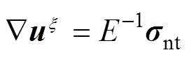 (10)
(10)
式中, 为边界载荷的预应力。
设置螺栓的材料属性,其密度为7.85 g/cm3,弹性模量为210 GPa,泊松比为0.31。当边界载荷为压应力16 MPa时,SRMA定子的应力分布如图8所示,可知,应力作用下定子铁心应力呈不均匀分布,且变形主要集中在定子齿部。
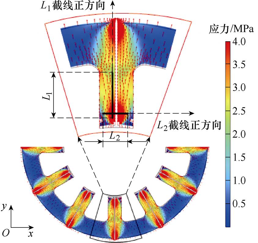
图8 16 MPa压应力下定子铁心应力分布
Fig.8 Stress distribution of stator core under 16 MPa compressive stress
不同压应力下定子齿顶部的形变曲线如图9所示,可知,随着压应力的增加,齿顶形变逐渐变大且螺栓所在位置形变最大。不同压应力下齿顶形变的极值相对于气隙长度(0.4 mm)的占比见表2,当压应力为20 MPa时,螺栓选材满足工艺要求,齿顶的最大形变量为0.738 mm,仅占气隙的0.184 %。因此,螺栓对定子的压应力不会影响SRMA的定转子齿槽配合,定子齿加压结构可以保证电机正常运行。
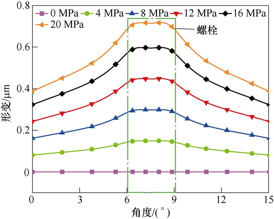
图9 不同压应力下定子齿顶形变
Fig.9 Deformation of the stator tooth top under different compressive stresses
表2 定子齿形变的气隙占比
Tab.2 The ratio of air gap to stator tooth deformation
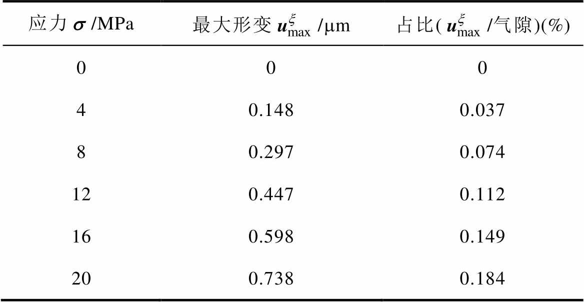
应力/MPa最大形变/mm占比(/气隙)(%) 000 40.1480.037 80.2970.074 120.4470.112 160.5980.149 200.7380.184
为了准确地模拟应力对SRMA定子非晶合金材料磁特性的影响,即磁致伸缩及其逆效应,本文建立SRMA的力-磁双向耦合模型,流程如图10所示。
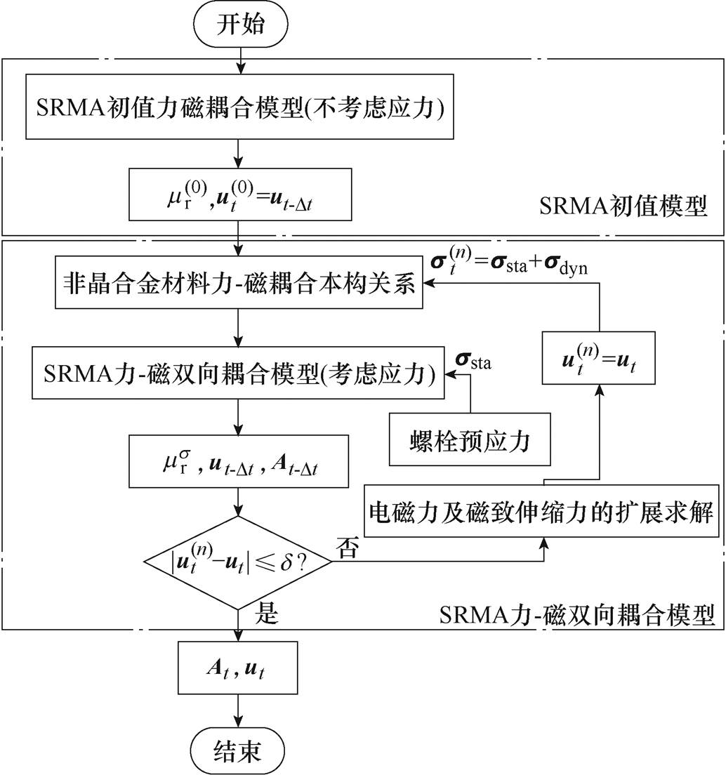
图10 SRMA力-磁双向耦合模型流程
Fig.10 Flow chart of SRMA force-magnetic two-way coupling model
首先,对模型进行初始化,获得非晶合金材料力-磁耦合本构关系中的非线性初始相对磁导率mr,计算不考虑应力作用的力-磁耦合模型初值。
由于SRMA工作于低频的运行状态,可忽略位移电流的影响,因此,初值化模型磁场求解域中的泊松方程为
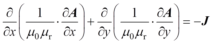 (11)
(11)
式中,J为电流密度;A为矢量磁位,满足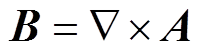 。
。
其次,以初始化模型参数为初值,更新非晶合金材料本构关系,并计算SRMA铁心的动态电磁力和磁致伸缩力初始值。为了实现应力对磁特性的反向耦合,即考虑磁致伸缩逆效应,需对SRMA铁心的动态电磁力和磁致伸缩力进行扩展求解。
采用麦克斯韦张量法计算电磁力,可表示为


 (12)
(12)
式中,S1为包围定转子铁心的环形曲线l1所围成的曲面,如图7所示;T为应力张量,可以表示为
 (13)
(13)
式中, 和
和 分别为磁通密度
 在x方向和y方向上的分量。
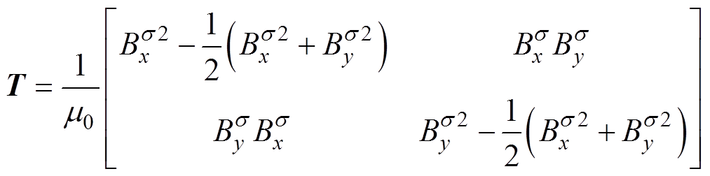
将式(12)所示电磁力进行正交分解,可得到考虑应力对磁特性反向耦合时定子齿顶处的径向电磁力Fn和切向电磁力Ft,即
 (14)
(14)
式中, 为磁通密度与x方向的夹角;l2为积分路径,本文选取位于定转子气隙中间位置处的环形曲线为电磁力积分路径,如图7所示。
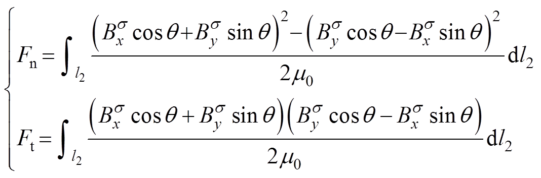
考虑应力对磁特性反向耦合的磁致伸缩应变可表示为
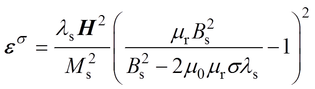 (15)
(15)
则考虑应力对磁特性反向耦合的磁致伸缩力可表 示为
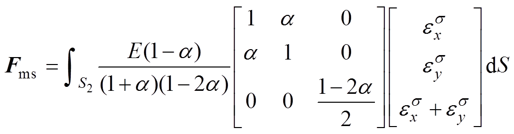 (16)
(16)
式中,S2为电机的定子区域面积; 和
和 分别为磁致伸缩应变
 的x方向和y方向分量;
 为泊松比,取0.25。
再次,根据电磁力和磁致伸缩力的扩展求解,建立考虑磁致伸缩及其逆效应的SRMA力-磁双向耦合模型,则耦合模型磁场求解域的泊松方程为
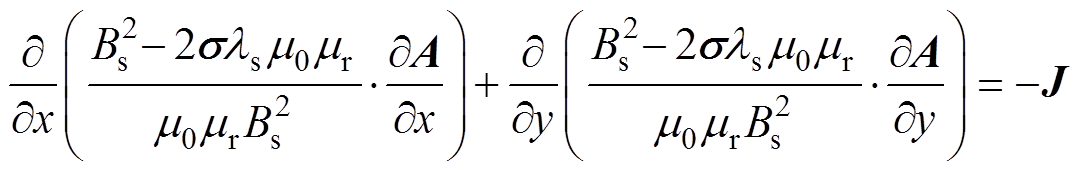 (17)
(17)
模型的磁机械耦合方程为
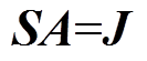 (18)
(18)
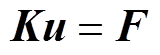 (19)
(19)
式中,S为电磁刚度矩阵;K为机械刚度矩阵;u为位移矩阵;F为力矩阵。
最后,基于上述模型进行迭代求解。将t~Dt时刻的位移值 作为t时刻迭代的初始值
 代入至非晶合金本构关系方程,通过力-磁双向耦合模型计算t时刻的位移矢量ut和磁矢势At,比较ut与的大小,满足以下条件时
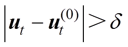 (20)
(20)
式中, 为设定的误差允许值。令
 =ut,并将预应力ssta和动态应力sdyn(电磁应力及磁致伸缩应力)代入非晶合金本构关系方程,重复双向动态耦合的迭代过程,在经过n次迭代后得到t时刻的磁矢势
 和
和 ,如果满足式(21)收敛条件,则计算结束。
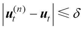 (21)
(21)
为分析定子侧的电磁振动特性,搭建SRMA的等效驱动电路以得到力-磁双向动态耦合有限元模型A、B、C三相绕组的励磁电流。等效驱动回路电路如图11所示。图中,LA~LC、L1a~L1c、RA~RC分别为等效SRMA的绕组电感、漏感及电阻,VD1~VD12为二极管,UDC为直流电压源,VSA~VSC为电压检测元件,R1~R3为限流电阻。
驱动回路电路中使用续流二极管和可控电压开关来等效实际SRMA控制回路中的可控器件,即通过设置脉冲电压VA~VC的大小给开关管提供动作电压,来控制可控电压开关S1~S6的工作状态以实现电路的开通和关断。在可控开关作用下,励磁电流按照A-B-C相的顺序循环导通,同时定义各向的开通角、关断角及导通周期。设置转速为1 500 r/min,对驱动电路仿真得到各相励磁电流波形,如图12所示。对A相电流进行频谱分析,如图13所示,等效驱动电路所得励磁电流的直流分量含量较高,谐波主要为2次和3次谐波。
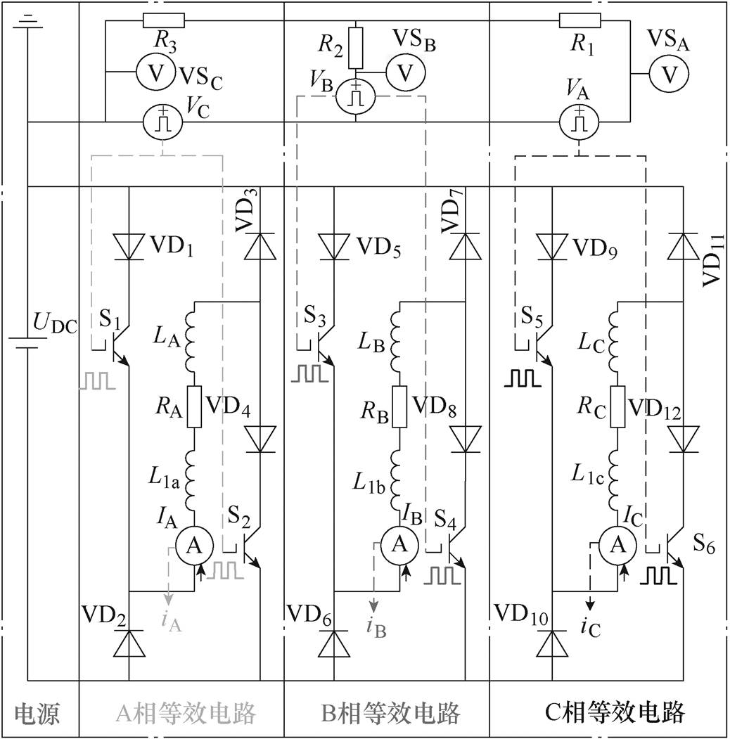
图11 SRMA等效驱动电路
Fig.11 Equivalent drive circuit of SRMA
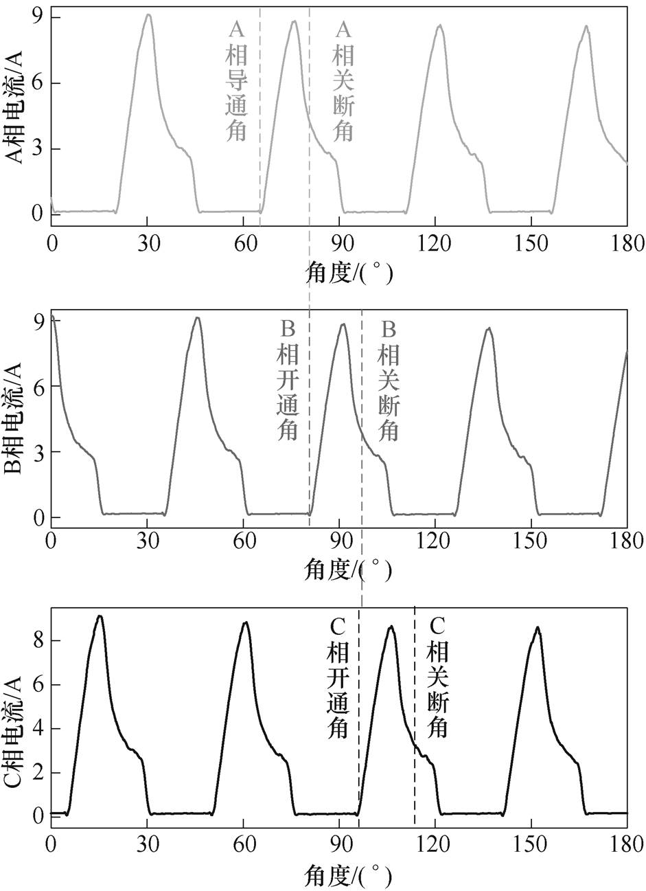
图12 SRMA三相电流曲线
Fig.12 Three-phase currents curves of SRMA
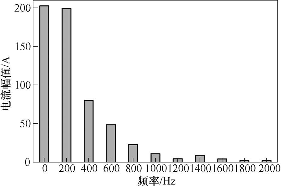
图13 励磁电流频谱
Fig.13 Spectrum of excitation current
因1K101铁基非晶合金材料自身磁特性优于45号钢,因此在定子铁心打孔加装螺栓会引起铁心打孔处的磁特性下降。为充分探究磁特性下降是否会对SRMA的工作状态产生影响,以图12所示的三相电流作为SRMA力-磁双向耦合模型的激励,对改进前后的电机定转子磁场分布进行模拟,如图14所示。可知,在同一时刻,改进前后电机定子轭部的磁通密度均为0.3 T左右,由于电机的主磁路主要分布于定子轭部,因此,改进结构不影响SRMA正常工作时的磁化状态;同时,改进前定子齿与转子齿重合时,齿顶位置磁通密度相对集中并出现磁通密度饱和现象,约为1.92 T,改进后,在相同位置的饱和磁通密度变小,约为1.71 T,因此,改进的定子齿加压结构可抑制电机铁心磁通密度的局部饱和问题。此外,在满足应力、工艺要求的前提下,采用高导磁材料制作螺栓可有效削弱定子铁心打孔对铁心磁特性的影响。
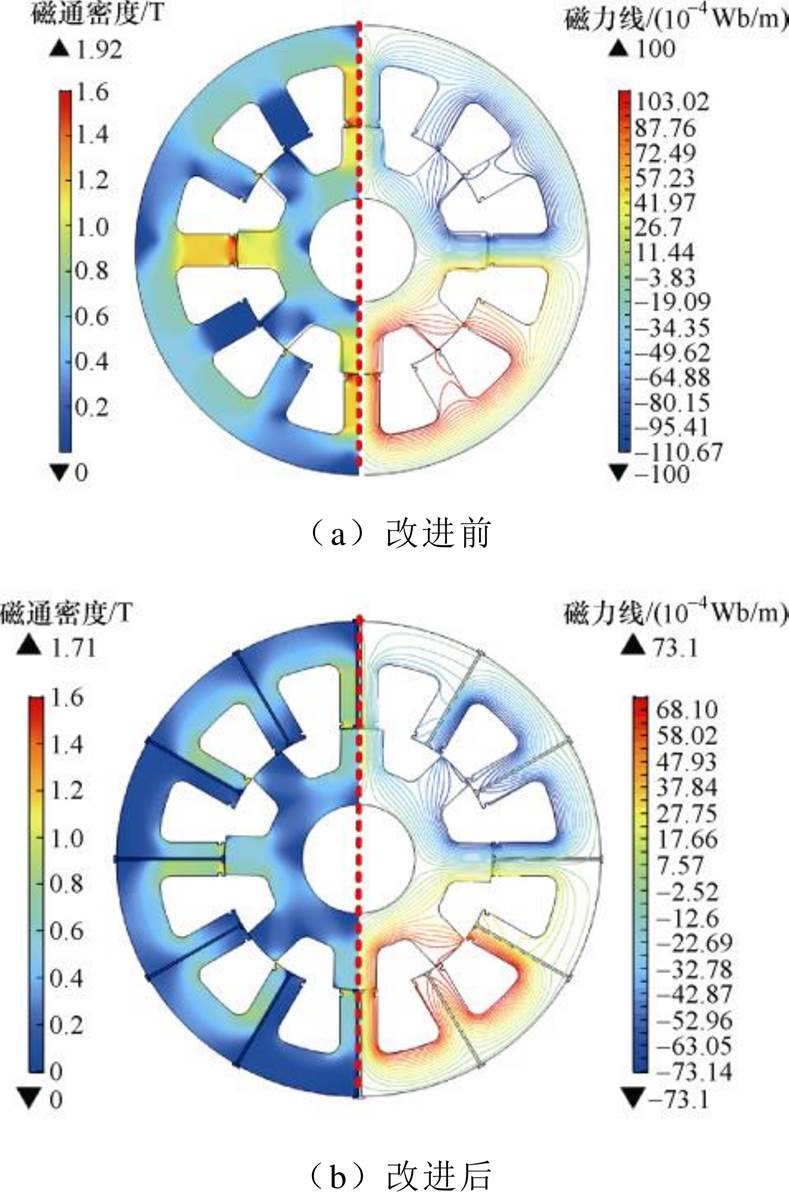
图14 改进前后SRMA磁通密度及磁力线分布
Fig.14 Magnetic flux density and magnetic field line distribution of SRMA before and after improvement
为了研究磁致伸缩效应对SRMA定子铁心振动的影响,分别对SRMA力-磁双向耦合模型考虑和不考虑磁致伸缩效应进行仿真,不同时刻SRMA定子铁心的应力及形变分布如图15所示,对比可知,SRMA定子铁心齿部形变较大,且考虑磁致伸缩效应时定子齿部的应力和形变更大,磁致伸缩力在动态力中的占比最高可达42.4 %。
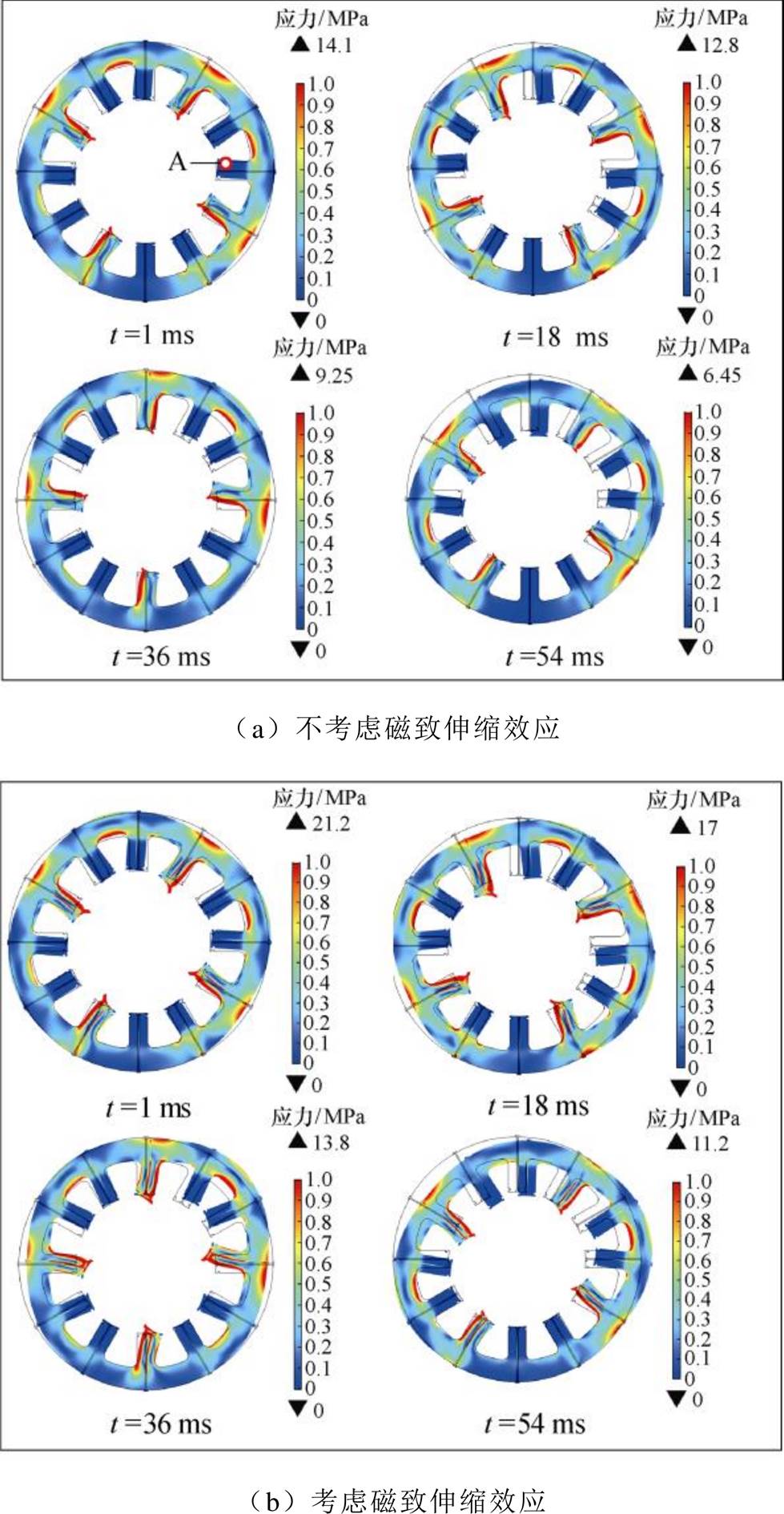
图15 SRMA定子铁心应力及形变
Fig.15 Stress and deformation of SRMA stator core
为了分析SRMA定子铁心振动随时间的变化特性以及磁致伸缩效应对其影响,选定子齿区域的A点(见图15)进行分析,A点应力随时间变化曲线如图16所示,可知,应力随时间变化的周期为5 ms,即振动频率包含200 Hz,是电源频率的基频,因此,电磁振动主要来源为磁致伸缩效应和电磁力;同时,当模型考虑磁致伸缩效应时,A点最大应力值相比于模型不考虑磁致伸缩效应时增加了52.8 %。因此,在分析SRMA的减振方法时,磁致伸缩效应对振动的影响不可忽略。
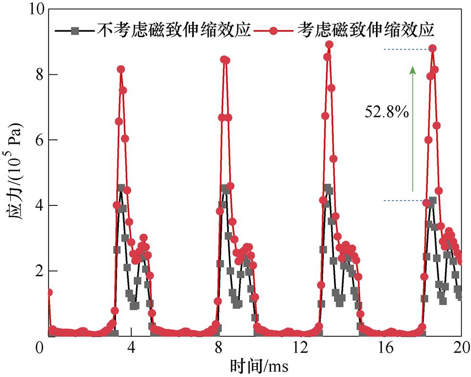
图16 采样点A处应力曲线
Fig.16 Stress curves at sampling point A
在SRMA运行过程中,由于铁心中力-磁双向耦合作用,应力会影响电机铁心中的磁通密度分布,为了分析其影响,在施加24 MPa的定子齿压应力后,从定子齿顶部选取纵向截线L1和横向截线L2(截线分布如图8所示),沿截线正方向计算截线各点的径向磁通密度,分布如图17和图18所示。
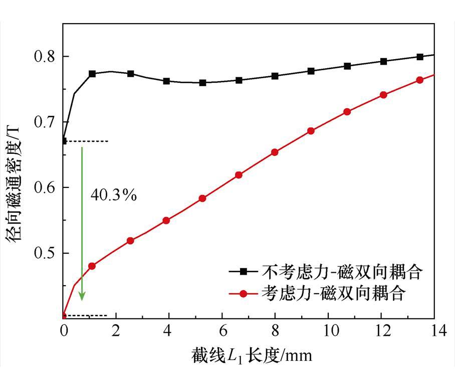
图17 纵向截线上径向磁通密度分布
Fig.17 Distribution of radial magnetic flux density on longitudinal section
由图17和图18可知,考虑力-磁双向耦合作用后,在电机定子加压结构的螺栓区域,磁通密度变小,其中,在电机定子齿的纵向方向上,径向磁通密度最大减小40.3 %,在定子齿的横向方向上,径向磁通密度最大减小32.1 %,且随着距螺栓距离的增大,力-磁耦合作用减小,这是由于在远离螺栓区域,其施加给铁心的应力减小造成的。
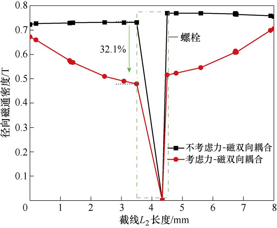
图18 横向截线上径向磁通密度分布
Fig.18 Distribution of radial magnetic flux density on transverse section
为了分析SRMA定子齿加压结构的减振效果,计算沿气隙路径l2(l2分布如图7所示)的径向磁通密度和径向电磁应力分布,分别如图19和图20所示。可以看出,通过螺栓给定子齿施加大小为24 MPa的压应力后,螺栓孔处的径向磁通密度和径向电磁应力显著降低,非螺栓区域的气隙径向磁通密度的最大值减小26.3 %,气隙径向电磁应力减小44.5 %。
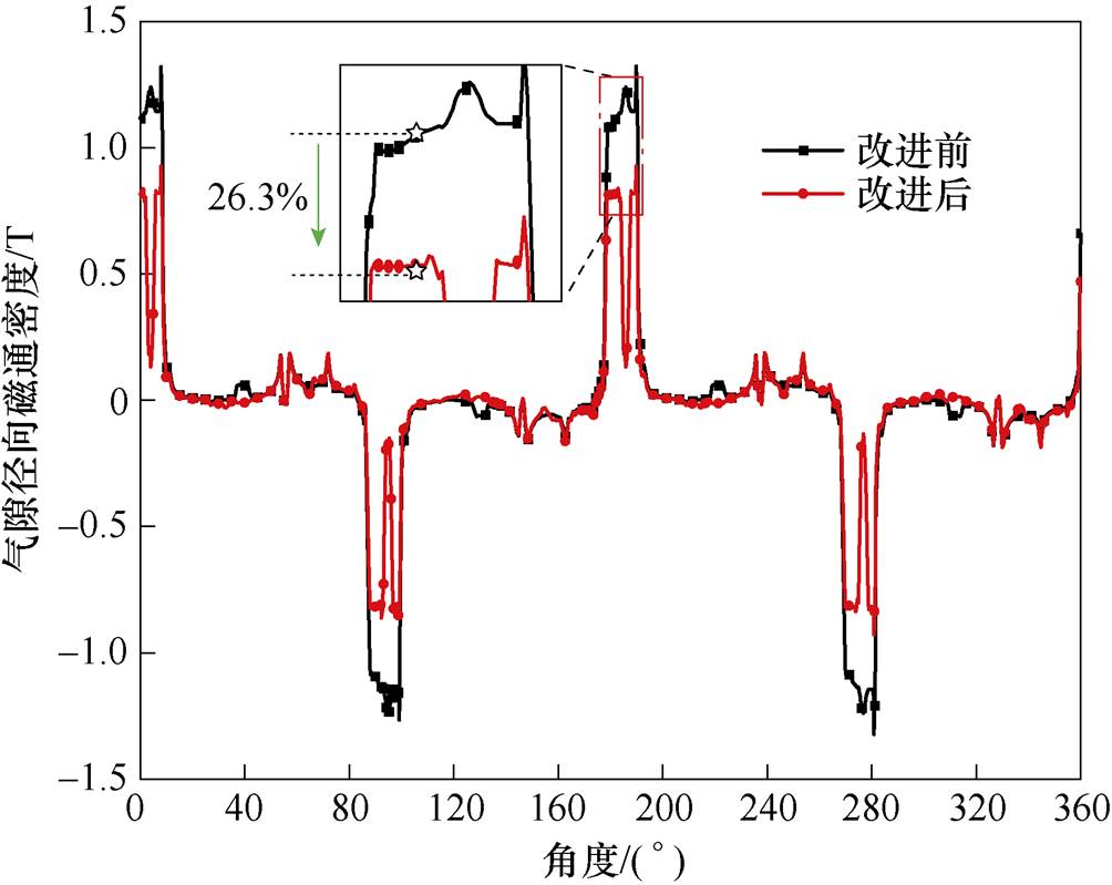
图19 气隙径向磁通密度分布
Fig.19 Distribution of radial magnetic flux density in the air gap
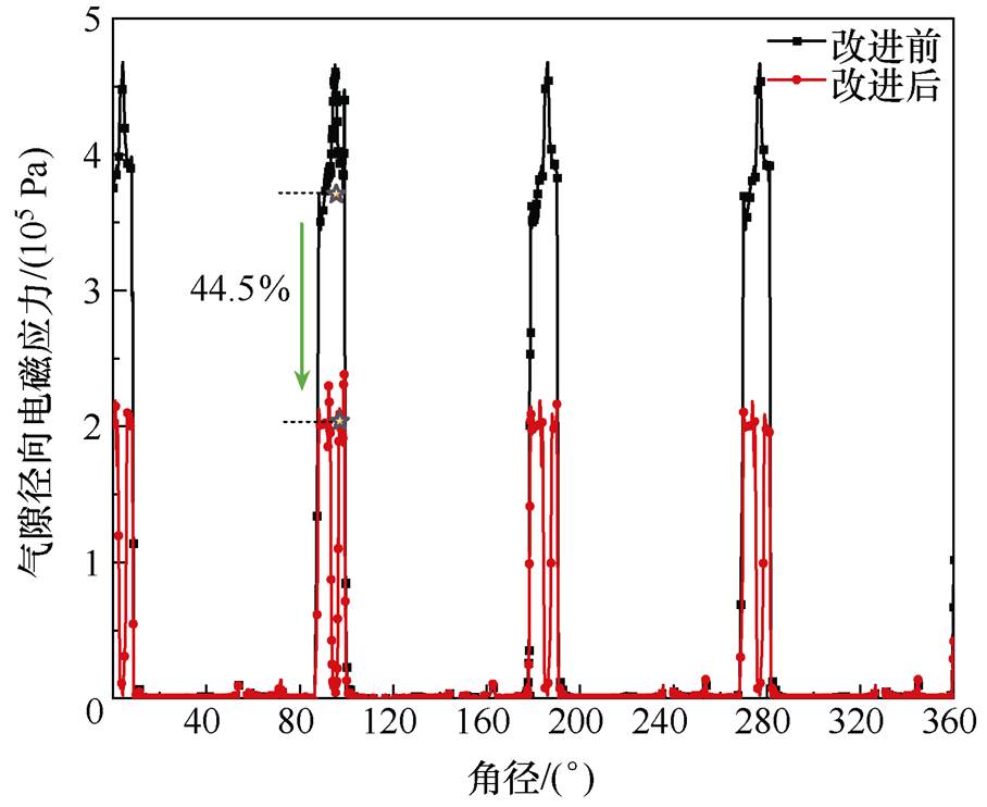
图20 气隙径向电磁应力分布
Fig.20 Distribution of radial electromagnetic stress in the air gap
为验证仿真结果的准确性,制作与仿真参数一致的SRMA样机并搭建振动位移测量平台,如图21a所示。其中,选用0~25 N·m规格的磁粉制动器作为实验负载,其大小由张力控制器调节至5 N·m;实验中,样机的底部固定,实验样机的激励、转速(1 500 r/min)等参数与仿真样机相同;选择测量点位置在正对定子齿的铁心上表面,即在SRMA内部的定子铁心上径向粘贴单轴应变片,如图21b所示,通过动态应变仪(型号:DPM-911B)测量电机铁心的径向应变;使用NI-PXIe6124多功能采集卡进行信号采集,振动位移测量结果如图22所示。
由图22a可知,仿真结果略小于实验结果,主要原因为:实验样机的实际转速并非恒定在1 500 r/min,而是在1 497~1 504 r/min的范围内上下浮动,实验样机的制造与安装存在不可避免的机械偏差等,但仿真与实验结果的误差在合理的范围内;由图22b可知,实验结果的频谱主要分布在200、400、600、800 Hz,为励磁电流主要频率的一次项及二次方项,因此,虽然仿真与实验结果存在误差,但其频谱分布一致,且误差在合理的范围内;可验证本文提出的考虑磁致伸缩及其逆效应的非晶合金开关磁阻电机模型的准确性。
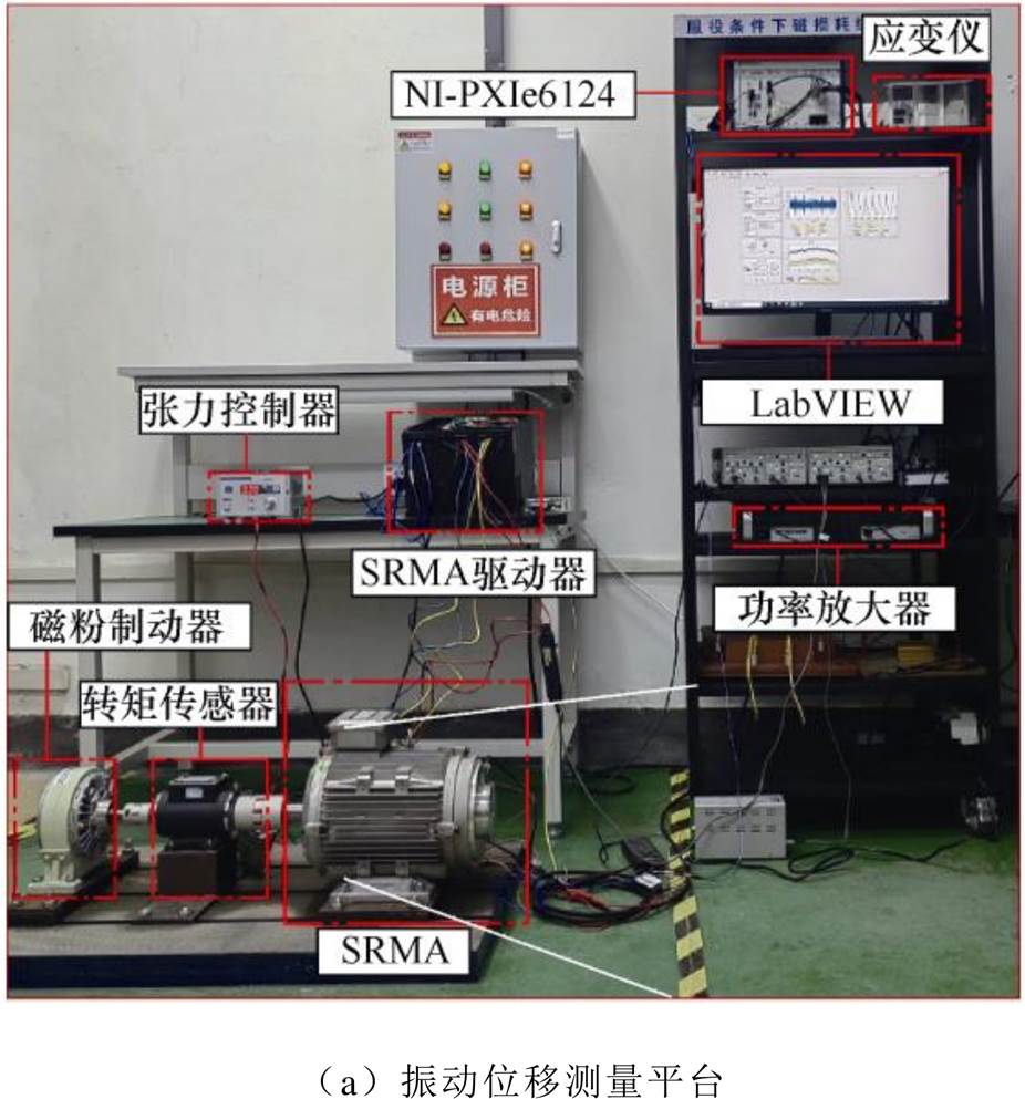
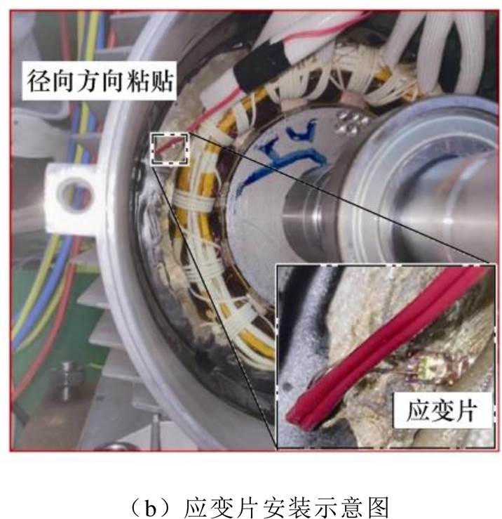
图21 SRMA振动测量实验
Fig.21 Vibration measurement experiment of SRMA
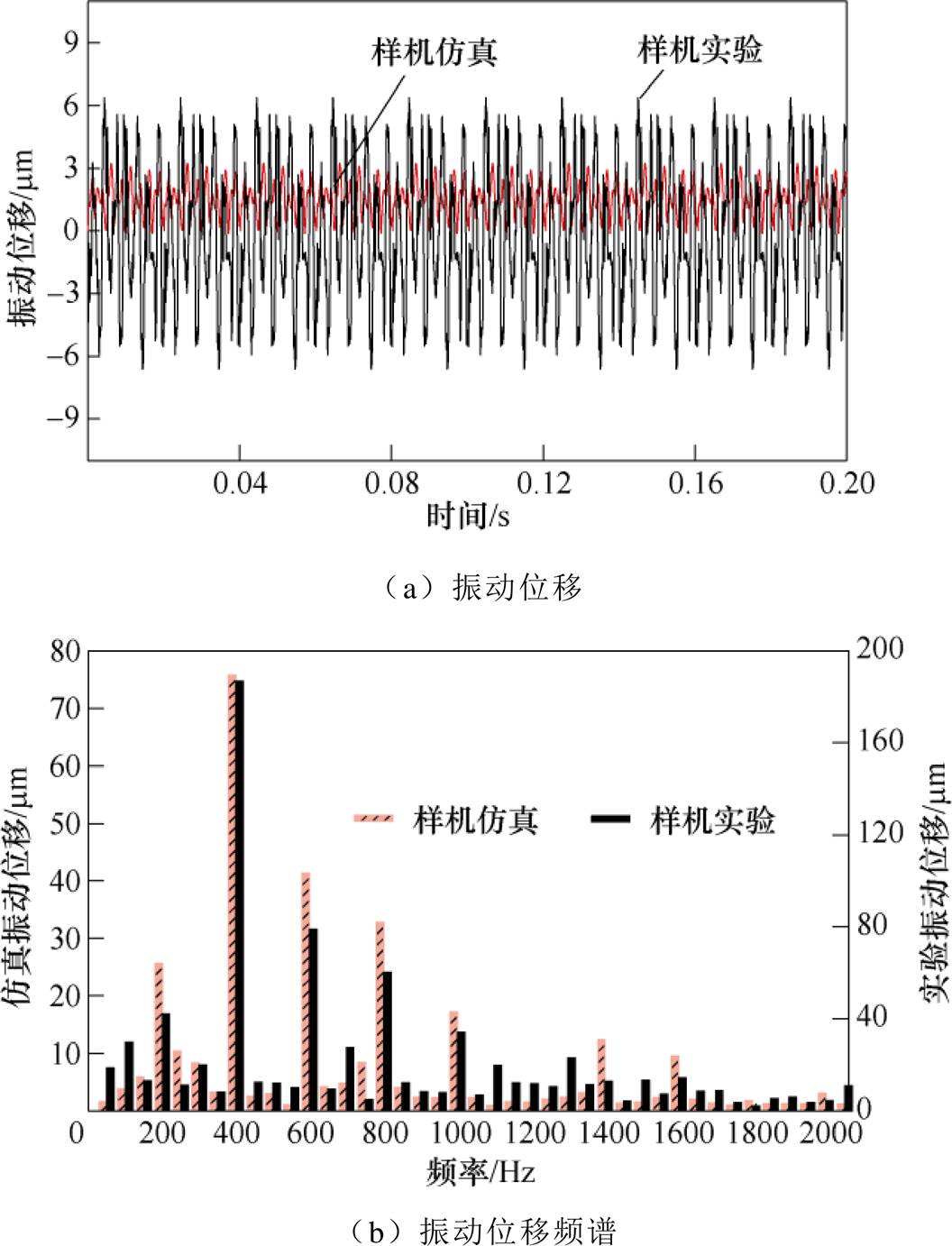
图22 径向振动位移
Fig.22 The vibration displacement in radial direction
本文提出非晶合金材料的力-磁耦合本构关系,并设计一种新型的开关磁阻电机定子齿加压结构,利用非晶合金的磁致伸缩逆效应,对开关磁阻电机进行减振研究,得出以下结论:
1)提出的非晶合金材料力-磁耦合本构关系,可描述应力对材料相对磁导率的非线性影响,能够用于模拟非晶合金的磁致伸缩及其逆效应。
2)提出考虑开关磁阻电机的力-磁双向动态耦合模型,模型仿真结果表明:磁致伸缩力在电机动态力中的占比最高可达42.4 %,其对开关磁阻电机电磁振动的影响不可忽略。
3)提出的定子齿加压结构相较于传统电机,气隙的径向磁通密度和电磁应力分别减小26.3 %、44.5 %,为非晶合金开关磁阻电机的减振研究提供了新思路。
参考文献
[1] 闫文举, 陈昊, 马小平, 等. 不同转子极数下磁场解耦型双定子开关磁阻电机的研究[J]. 电工技术学报, 2021, 36(14): 2945-2956.
Yan Wenju, Chen Hao, Ma Xiaoping, et al. Develop- ment and investigation on magnetic field decoupling double stator switched reluctance machine with different rotor pole numbers[J]. Transactions of China Electrotechnical Society, 2021, 36(14): 2945-2956.
[2] 闫文举, 陈昊, 刘永强, 等. 一种用于电动汽车磁场解耦型双定子开关磁阻电机的新型功率变换器[J]. 电工技术学报, 2021, 36(24): 5081-5091.
Yan Wenju, Chen Hao, Liu Yongqiang, et al. A novel power converter on magnetic field decoupling double stator switched reluctance machine for electric vehicles[J]. Transactions of China Electrotechnical Society, 2021, 36(24): 5081-5091.
[3] 王立军, 张广强, 李山红, 等. 铁基非晶合金应用于电机铁芯的优势及前景[J]. 金属功能材料, 2010, 17(5): 58-62.
Wang Lijun, Zhang Guangqiang, Li Shanhong, et al. Advantages and prospects of Fe-based amorphous alloy materials applied in motor iron core[J]. Metallic Functional Materials, 2010, 17(5): 58-62.
[4] Ismagilov F R, Papini L, Vavilov V E, et al. Design and performance of a high-speed permanent magnet generator with amorphous alloy magnetic core for aerospace applications[J]. IEEE Transactions on Industrial Electronics, 2020, 67(3): 1750-1758.
[5] 杨庆新, 李永建. 先进电工磁性材料特性与应用发展研究综述[J]. 电工技术学报, 2016, 31(20): 1-29.
Yang Qingxin, Li Yongjian. Characteristics and developments of advanced magnetic materials in electrical engineering: a review[J]. Transactions of China Electrotechnical Society, 2016, 31(20): 1-29.
[6] 张国忠, 李艳辉, 吴立成, 等. Fe基纳米晶软磁合金退火脆性的研究进展[J]. 材料导报, 2020, 34(3): 171-177.
Zhang Guozhong, Li Yanhui, Wu Licheng, et al. Research progress on annealing embrittlement of Fe-based nanocrystalline soft magnetic alloys[J]. Materials Reports, 2020, 34(3): 171-177.
[7] 匡斯建, 张小平, 刘苹, 等. 基于相电感非饱和区定位的开关磁阻电机无位置传感器控制方法[J]. 电工技术学报, 2020, 35(20): 4296-4305.
Kuang Sijian, Zhang Xiaoping, Liu Ping, et al. Sensorless control method for switched reluctance motors based on locations of phase inductance characteristic points[J]. Transactions of China Elec- trotechnical Society, 2020, 35(20): 4296-4305.
[8] 卿龙, 王惠民, 葛兴来. 一种高效率开关磁阻电机转矩脉动抑制方法[J]. 电工技术学报, 2020, 35(9): 1912-1920.
Qing Long, Wang Huimin, Ge Xinglai. A high effi- ciency torque ripple suppression method for switched reluctance motor[J]. Transactions of China Electro- technical Society, 2020, 35(9): 1912-1920.
[9] 张鑫, 王秀和, 杨玉波. 基于改进磁场分割法的开关磁阻电机径向力波抑制能力解析计算[J]. 电工技术学报, 2015, 30(22): 9-18.
Zhang Xin, Wang Xiuhe, Yang Yubo. The com- putation of vibration reduction capacity for switched reluctance motor based on improved magnetic field partition method[J]. Transactions of China Electro- technical Society, 2015, 30(22): 9-18.
[10] Sahin C, Amac A E, Karacor M, et al. Reducing torque ripple of switched reluctance machines by relocation of rotor moulding clinches[J]. IET Electric Power Applications, 2012, 6(9): 753.
[11] Yang Yubo, Yang Xiaotong, Chen Peng, et al. Electromagnetic performance analysis of hybrid excited segmental rotor flux switching machine[J]. IEEE Transactions on Magnetics, 2018, 54(11): 1-5.
[12] 张欣, 解超群, 祝丽花, 等. 考虑磁致伸缩效应的电机应力数值仿真与实验[J]. 电工技术学报, 2017, 32(增刊2): 50-55.
Zhang Xin, Xie Chaoqun, Zhu Lihua, et al. Numerical simulation and experimental research on stress of motor including magnetostriction effects[J]. Transa- ctions of China Electrotechnical Society, 2017, 32(S2): 50-55.
[13] 张鹏宁, 李琳, 聂京凯, 等. 考虑铁心磁致伸缩与绕组受力的高压并联电抗器振动研究[J]. 电工技术学报, 2018, 33(13): 3130-3139.
Zhang Pengning, Li Lin, Nie Jingkai, et al. Study on the vibration of high voltage shunt reactor considering of magnetostriction and winding force[J]. Transa- ctions of China Electrotechnical Society, 2018, 33(13): 3130-3139.
[14] 吴胜男, 于慎波, 佟文明, 等. 磁致伸缩引起的径向磁通电机定子铁心振动精确解析模型[J]. 电工技术学报, 2019, 34(2): 226-235.
Wu Shengnan, Yu Shenbo, Tong Wenming, et al. A precise analytical model of stator core vibration due to magnetostriction for radial flux motors[J]. Transa- ctions of China Electrotechnical Society, 2019, 34(2): 226-235.
[15] Wang Zhen, Zhang Yanli, Ren Ziyan, et al. Modeling of anisotropic magnetostriction under DC bias based on an optimized BP neural network[J]. IEEE Transa- ctions on Magnetics, 2020, 56(3): 1-4.
[16] Zhang Pengning, Li Lin, Cheng Zhiguang, et al. Study on vibration of iron core of transformer and reactor based on maxwell stress and anisotropic magneto- striction[J]. IEEE Transactions on Magnetics, 2019, 55(2): 1-5.
[17] 迟青光, 张艳丽, 陈吉超, 等. 非晶合金铁心损耗与磁致伸缩特性测量与模拟[J]. 电工技术学报, 2021, 36(18): 3876-3883.
Chi Qingguang, Zhang Yanli, Chen Jichao, et al. Measurement and modeling of lossand magneto- strictive properties for the amorphous alloy core[J]. Transactions of China Electrotechnical Society, 2021, 36(18): 3876-3883.
[18] 韩雪岩, 赵森磊, 周挺, 等. 非晶合金电机振动噪声影响因素的研究[J]. 电工技术学报, 2015, 30(14): 531-538.
Han Xueyan, Zhao Senlei, Zhou Ting, et al. Research on vibration and noise of a amorphous metal motor[J]. Transactions of China Electrotechnical Society, 2015, 30(14): 531-538.
[19] Zivotsky O, Hendrych A. Influence of tensile stress on the surface magneto-optical hysteresis loops in amorphous and (nano) crystalline ribbons[J]. IEEE Transactions on Magnetics, 2014, 50(4): 1-4.
[20] 贲彤, 陈芳媛, 陈龙, 等. 考虑力-磁耦合效应的无取向电工钢片磁致伸缩模型的改进[J]. 中国电机工程学报, 2021, 41(15): 5361-5371.
Ben Tong, Chen Fangyuan, Chen Long, et al. An improved magnetostrictive model of non-oriented electrical steel sheet considering force-magnetic coupling effect[J]. Proceedings of the CSEE, 2021, 41(15): 5361-5371.
Abstract Switched reluctance motors are applied in electric vehicles due to their simple structure and low cost. The amorphous alloy used in the switched reluctance motor core can greatly improve the efficiency of the motor. However, its large magnetostrictive coefficient and strong stress sensitivity (i.e. inverse-magnetostriction effect) will increase the core vibration and limit the precise control ability of electrical signals. Therefore, a new approach is proposed to use the inverse-magnetostriction effect to control the electromagnetic vibration of switched reluctance motors with amorphous alloy cores (SRMA). Then, the compressive stress applied structure of the SRMA stator teeth is proposed. The simulation and experimental results show that the vibration reduction method is feasible.
Firstly, a nonlinear magnetostriction and inverse-magnetostriction effect force-magnetic coupling con- stitutive relation of the amorphous alloy is proposed based on the macroscopic thermodynamics to analyze the vibration of a SRMA. The parameters are measured by magnetic properties measurement system. Thus, the magnetostrictive strain and relative permeability of amorphous alloys with a magnetic field and compressive stress applied can be calculated. Secondly, the compressive stress applied structure of the SRMA is proposed according to the inverse-magnetostriction effect, and a finite element model of the structure is established to verify its stability. Then, according to the extended solution of the electromagnetic stress and magnetostrictive stress, a two-way dynamic electromagnetic-force coupling model of the SRMA considering the magnetostriction and inverse-magnetostriction effects is established. Finally, experiments and finite element calculations are carried out on the vibration characteristics of SRMA. The magnetic flux density in the stator yoke area remained at about 0.3 T before and after the improvement, which shows that the SRMA can still maintain the original running state after the improvement. Furthermore, the finite element calculation results before and after considering the magnetostriction of the SRMA stator are compared. It is shown that the main sources of vibration are magnetostrictive stress and electromagnetic stress. Among them, the proportion of magnetostrictive stress in dynamic stress can reach up to 42.4 %. Besides, after the stator teeth are applied to 24 MPa compressive stress, the radial magnetic flux density near the bolt is significantly reduced due to the force-magnetic coupling, and the radial magnetic flux density and electromagnetic stress in the air gap are reduced by 26.3 % and 44.5 %, respectively. By comparing the experimental and simulation results of the vibration displacement, the spectral distribution is consistent, which verifies the accuracy of the proposed SRMA model.
The following conclusions can be drawn from the simulation and experiment analysis: (1) The proposed force-magnetic coupling constitutive relation of the amorphous alloy can simulate the magnetostriction and the inverse-magnetostriction effect, and the nonlinear effect of stress on the relative permeability of amorphous alloys can be described more accurately. (2) By solving the two-way dynamic electromagnetic-force coupling model of the SRMA, the magnetostriction effect cannot be ignored in the vibration analysis of SRMA. (3) The compressive stress applied structure of the stator teeth can reduce vibrations while maintaining the original operation of the SRMA. It provides a new idea for research on the vibration reduction of SRMAs.
keywords:Inverse-magnetostriction effect, magnetostriction effect, electromagnetic vibration, vibration reduction method of switched reluctance motor, amorphous alloy
DOI: 10.19595/j.cnki.1000-6753.tces.220493
中图分类号:TM352
国家自然科学基金(52007102, 52207012)和省部共建电工装备可靠性与智能化国家重点实验室(河北工业大学)开放课题基金(EERI_KF2021015)资助项目。
收稿日期 2022-04-02
改稿日期 2022-08-23
贲 彤 女,1991年生,博士,副教授,硕士生导师,研究方向为开关磁阻电机电磁综合效应。E-mail: bentong@ctgu.edu.cn
陈 龙 男,1989年生,博士,讲师,硕士生导师,研究方向为磁性材料磁特性模拟、全局优化设计。E-mail: chenlong@ctgu.edu.cn(通信作者)
(编辑 崔文静)