 (1)
(1)
摘要 该文提出一种基于动态无功补偿技术的磁平衡式电流互感器设计方法,其应用能够实现对大范围波动电流的精确测量。通过对电流互感器工作原理及其测量误差的分析,提出基于动态无功补偿的磁平衡式电流互感器控制算法,即采用自适应扰动法实现对电流互感器二次侧测量电流的最大电流跟踪。建立了基于Comsol和Simulink联合仿真的磁平衡式电流互感器场-路耦合模型,仿真和实验验证了所提出磁平衡式电流互感器模型的有效性以及控制算法的可行性。
关键词:无功补偿 磁平衡式电流互感器 场-路耦合模型 自适应扰动法
为了监测电网的运行状况,常使用电流互感器(Current Transformer, CT)等装置检测电力系统中的电流[1-4]。其中,CT是基于电磁感应原理的测量器件,在测量过程中,由于CT一次电流中的一部分用于铁心励磁,而铁心中存在铁磁损耗,因此,励磁电流不仅是CT正常工作的必要条件,同时也是CT测量误差的主要来源[5-6]。如何消除励磁电流的影响是提高CT测量精度的关键。目前,降低CT测量误差的主要措施是对励磁电流进行补偿,补偿方法可分为有源补偿法和无源补偿法两类。
有源补偿法是通过外部施加激励来补偿励磁电流,进而提高CT的测量精度[7]。该类方法包括电动势补偿法和磁动势补偿法等。电动势补偿法是在CT二次绕组串联一个外加电动势,从而增大二次绕组上的电流,但该方法稳定性差,容易出现能量倒灌等情况,因此无法实际应用。磁动势补偿法通常采用双级铁心,在主铁心的测量绕组上串接一个测量仪表,而利用辅助铁心上的补偿绕组来补偿CT中的励磁磁动势,该方法结构复杂,而测量仪表在实际工作时会引入测量误差。
无源补偿法包括匝数补偿法和电容补偿法等[8-9]。匝数补偿法是在原CT匝数比不变的前提下,通过减小CT二次侧匝数来提高二次电流,从而使其逼近理想CT的二次电流,但该方法测量精度低、实用性差。电容补偿法是在CT二次侧并联电容用于CT等效电感的无功补偿,但CT铁心的励磁过程是非线性的,固定参数电容难以实现准确的无功补偿。此外,大容量的电容价格昂贵,其经济性较差。
本文在容性补偿方法的基础上,提出了一种基于动态无功补偿技术的磁平衡式电流互感器设计方法,将其用于大范围波动电流的实时监测。通过在CT二次侧并联动态无功补偿电路,补偿CT中的励磁磁动势,从而提高CT的测量精度[10-13]。
CT一般由闭合铁心、一次和二次绕组组成,该器件可用于测量或保护等。对于理想电流互感器而言,电流与绕组匝数成反比,即
(1)
式中, 和
和 分别为CT一次和二次电流有效值;
 和
和 分别为一次和二次绕组匝数。
CT在实际应用中,一次和二次绕组的电阻电压和漏抗电压相比于其感应电动势均小很多,因此可忽略其影响,此时CT带载运行的磁动势平衡关系为
 (2)
(2)
式中, 、
、 和
和 分别为CT一次电流、二次电流和励磁电流。从式(2)可以看出,CT的测量误差主要由励磁磁动势
 引入。该误差通常可表示为
 (3)
(3)
式中, 为角差,是指次级磁动势
 逆时针旋转
逆时针旋转 与
与 的夹角;
的夹角; 为比差,有
为比差,有
 (4)
(4)
若CT的励磁电流可以被完全补偿,即 ,则CT可被看作理想电流互感器并可消除其测量误差。
磁平衡式CT的电路原理如图1所示,该CT主要由铁心、一次和二次绕组及二次侧电路组成。 为测量电阻,
 为动态无功补偿电路。其中,CT铁心采用铁基纳米晶材料,铁心内径、外径和高度分别为0.05m、0.1m和0.1m,一次和二次绕组匝数N1和N2分别为1和80。如图1所示,CT工作时的磁动势平衡方程为
 (5)
(5)
式中, 为CT二次侧流过的电流。式(5)整理后,可得
 (6)
(6)
式中, 为磁平衡式CT的等效励磁电流。
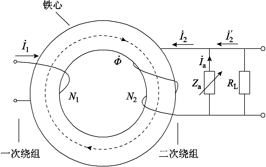
图1 磁平衡式CT电路原理
Fig.1 Circuit schematic of the flux balance CT
由图1和式(6)可知,调节CT二次侧可调阻抗用于模拟容抗,而且其与CT二次侧等效励磁感抗并联谐振时,等效励磁电流 近似为零,则CT可看作理想电流互感器,其测量误差最小。此时,CT一次电流
 与二次侧测量电流
 相位相差,流过测量电阻
 的电流为最大二次电流
 ,即满足
,即满足 。
。
本文选用电压型单相全桥脉冲宽度调制(Pulse Width Modulation, PWM)整流电路作为动态无功补偿电路的主电路,它是一种交、直流可控的电力电子变换器,其电路结构由交流侧回路、功率开关管桥路、直流侧回路构成,如图2所示。其中,交流侧回路包含交流电感 ,直流侧回路则包含直流电阻
 和直流储能电容
 。通过对整流桥进行开关控制,可以实现PWM整流电路的四象限运行,使交流侧电流在相位上超前或滞后交流侧电压
 ,从而对外呈现不同的负载特性[14],其交流侧相量关系如图3所示。
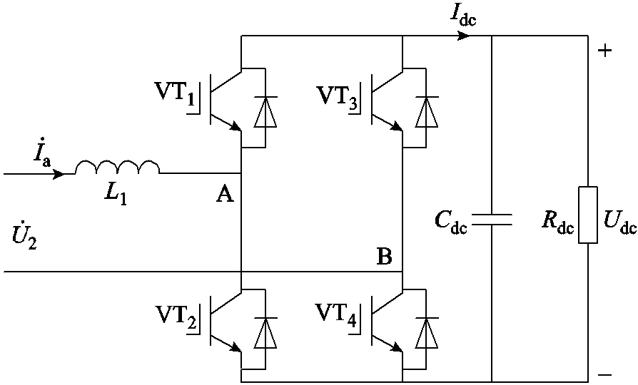
图2 电压型单相全桥PWM整流电路
Fig.2 Voltage type single-phase full-bridge PWM rectifier circuit

图3 无功补偿电路工作相量
Fig.3 Phasor diagram of reactive power compensation circuit
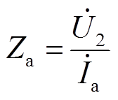
无功补偿电路工作相量如图3所示,为CT二次电压, 为交流侧电压,
 为交流侧电感两端电压,为交流侧电流,
 为和的功率因数角。控制相位超前
 ,使工作在容性负载模式下,其等效容抗可表示为
 (7)
(7)
故可通过调节的伏安关系,使其等效容抗始终与CT二次侧的等效感抗模值相等,从而实现对励磁磁动势的无功补偿。
当无功补偿电路的等效容抗与CT二次侧励磁电感并联谐振时,流过CT二次侧测量电阻的电流最大为,即
 (8)
(8)
CT一次电流大范围变化时,为了始终使二次电流有效值 跟踪
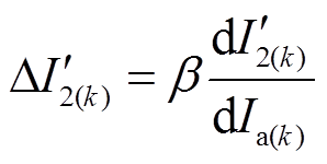
跟踪 ,本文依据最大功率跟踪算法[15-17],提出了一种跟踪最大电流的变步长自适应扰动法,其控制算法为
 (9)
(9)
式中, 为第k+1次无功补偿电路电流
 的参考值;
的参考值; 为第k次的电流值;
 为扰动步长。自适应扰动法原理如图4所示。

图4 自适应扰动法原理
Fig.4 Schematic diagram of adaptive disturbance method
由图4可知,当的工作点越接近于电流最大值时,电流变化的斜率越小,此时应减小扰动步长,使以较小的速度接近;当的工作点距离较远时,电流变化的斜率较大,此时应增大扰动步长,使以更快的速度接近。故扰动步长 的计算方法为
 (10)
(10)
式中, 为扰动步长调节因子。越大,则控制算法收敛速度越快,但其稳定性会降低;而越小,则收敛速度越慢,但其系统稳定性与控制精度越高[18-22]。针对不同系统及其控制要求,的取值亦不相同,其取值范围为0~1。根据磁平衡式CT测量电流时的动态特性及其准确性,自适应扰动法中的步长调节因子取为0.3。
基于以上对无功补偿电路的工作原理与控制算法分析,得出图5所示的控制算法流程以及图6所示的控制策略。采用准比例谐振(Quasi-Proportional Resonant, QPR)控制器控制,并用三角波调制法生成正弦波脉冲宽度调制(Sinusoidal PWM, SPWM)开关信号控制整流桥的工作状态[23-25]。
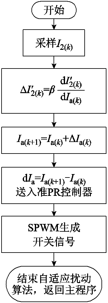
图5 算法流程
Fig.5 Algorithm flowchart
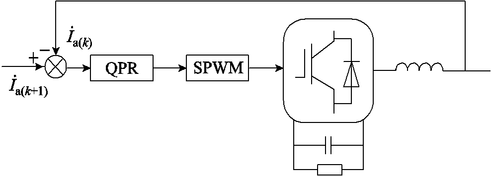
图6 控制策略
Fig.6 Control strategy
QPR控制器可以实现对正弦信号的无静差跟踪,其传递函数为
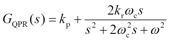 (11)
(11)
式中, 为比例系数;
 为谐振系数;
 为角频率;
为角频率; 为谐振角频率。
经QPR控制器处理后的信号在SPWM模块中与三角波进行调制,生成整流桥上功率开关管的控制信号。当SPWM模块中的载波比一定时,整流桥可以近似地看作一个比例环节,又因调制过程中存在一定的延时,故可将调制和整流桥整体看作惯性环节来分析,即
 (12)
(12)
式中, 为惯性时间常数;
 为放大倍数,且通常取值为
 ,
, 为三角载波的峰值。
此外,忽略线路阻抗的可调电子负载交流侧电路的传递函数可以表示为
 (13)
(13)
因此,电流环控制框图如图7所示。
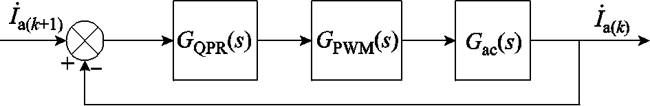
图7 电流环控制框图
Fig.7 Block diagram of current loop control
由图7可知,电流环闭环特征方程为
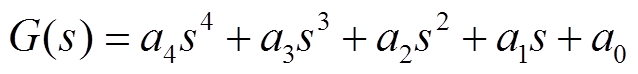 (14)
(14)
其中
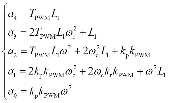 (15)
(15)
式中,控制参数取值分别为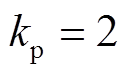 ;
; ;
; ;
; ;
; ;
; ;
; 。根据特征方程的系统构造劳斯阵列,其第一列元素为
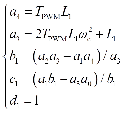 (16)
(16)
将控制参数值和特征方程系数式(15)代入到式(16)中,可得劳斯阵列第一列元素系数均为正,故动态无功补偿电路是稳定的。
本文建立了Comsol和Simulink联合仿真的磁平衡式电流互感器场-路耦合模型。
根据全电流定律,可得出CT仿真模型的磁场变化规律,CT绕组区域的控制方程为
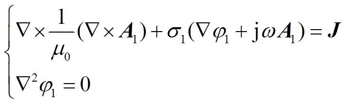 (17)
(17)
式中, 和
和 分别为导体区域的矢量位函数和标量位函数;
 为导体的电导率;
 为外施电流密度,可表示为
 (18)
(18)
式中, 和
和 分别为CT的
 (i=1,2)次绕组流过的电流和绕组导线的横截面积。
CT铁心区域的控制方程为
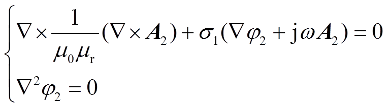 (19)
(19)
式中, 和
和 分别为铁心区域的矢量位函数和标量位函数;
 为铁心的电导率;
 为铁心材料的相对磁导率。
根据电磁感应定律可得CT二次绕组的感应电动势 有效值表达式为
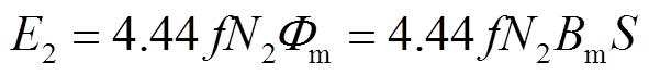 (20)
(20)
式中, 和
和 分别为CT铁心内磁通量和磁通密度的最大值;
 为铁心的有效截面积。
基于式(17)~式(20)建立了CT的磁场模型。接下来,基于Comsol与Simulink联合仿真搭建磁平衡式电流互感器的场-路耦合模型,如图8所示。
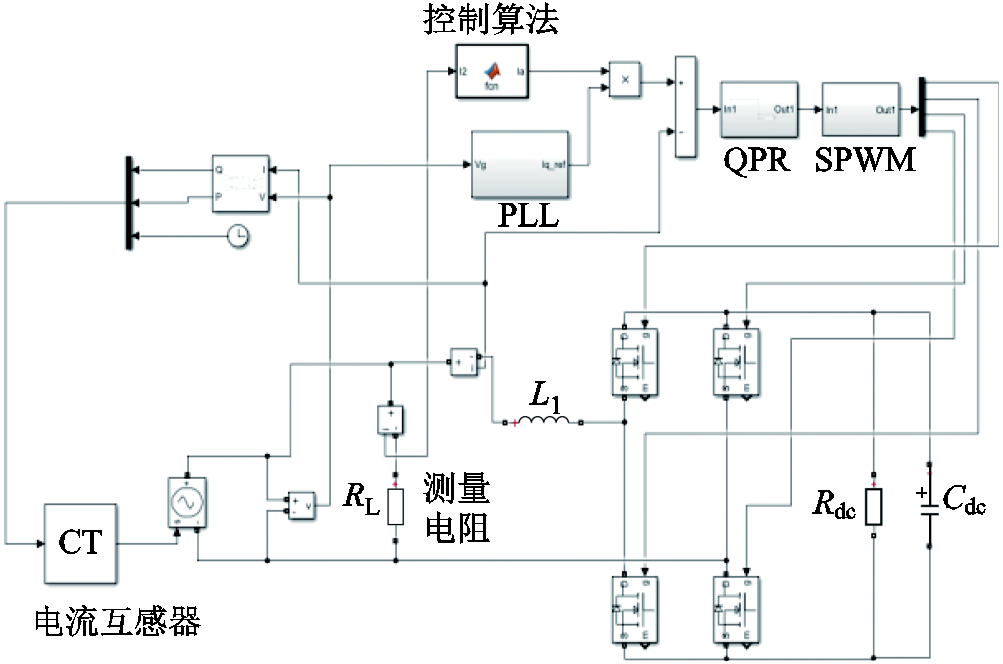
图8 Simulink仿真模型
Fig.8 Model diagram in Simulink
在S-Function模块中,建立了铁心的磁场模型。利用Matlab Function模块编写基于自适应扰动法的电流控制算法以实现对二次电流的最大电流跟踪。仿真参数与仿真结果见表1和表2,其中IN为CT的一次额定电流,CT几何结构、一次侧匝数、二次侧匝数和控制算法的设计参数均与第2节和3.2节保持一致。
表1 Simulink仿真参数
Tab.1 Simulation parameters
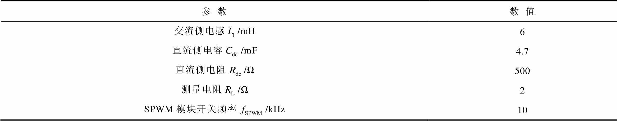
参数数值 交流侧电感/mH6 直流侧电容/mF4.7 直流侧电阻/Ω500 测量电阻/Ω2 SPWM模块开关频率/kHz10
表2 仿真结果
Tab.2 Simulation results

补偿前补偿后 5-2.465+76-0.56+28 10-1.394+48-0.43+21 20-0.859+30-0.24+14 80-0.523+23-0.15+9 100-0.374+18-0.09+7 120-0.321+14-0.09+8
从仿真结果可以看出,磁平衡式CT对比差补偿为正值,对角差补偿为负值,具有典型的电容无功补偿的特点[8]。在CT一次电流大范围波动时,与传统CT相比,磁平衡式CT测量精度有明显提高,具有0.2级精度。
本文搭建了磁平衡式电流互感器的实验电路,其原理如图9所示。采用大电流发生器作为待测电源,输出50Hz、30A(幅值)的正弦电流信号。CT铁心材料为铁基纳米晶,其内径、外径和高度分别为0.05m、0.1m和0.1m。CT的一次侧和二次侧匝数分别为1和80。动态无功补偿电路中,交流侧使用XDLK-10A型号的电抗器,用电桥表测得其电感值为6.3mH;直流侧使用4 700μF的铝电解电容器和144Ω的大功率电阻并联作为阻抗 ;整流桥选用FF300R17ME4型号的IGBT模块。二次侧实际测量电阻为1.7Ω。利用霍尔传感器对CT二次侧测量电流实时采样,并将采样后的电流信号通过A-D转换输入到dSPACE控制器中进行跟踪控制,依据图5所示的算法流程,生成动态无功补偿电路整流桥的开关控制信号。其中,系统控制参数与仿真参数一致。利用AP2008L-1-4手持式电能质量分析仪测量电流的实验结果。在示波器中得到CT一次电流以及补偿后的CT二次电流波形,如图10所示。
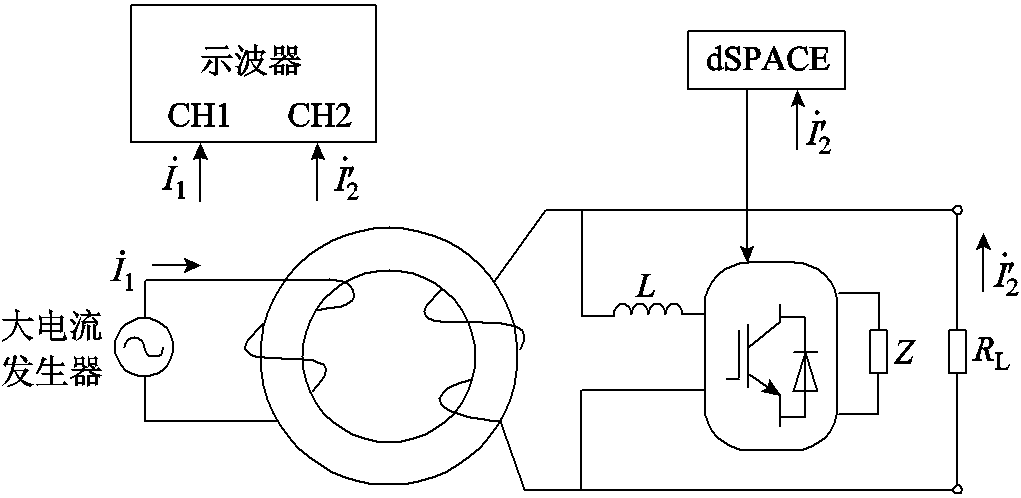
图9 磁平衡式电流互感器实验原理
Fig.9 Experimental schematic of flux balanced current transformer
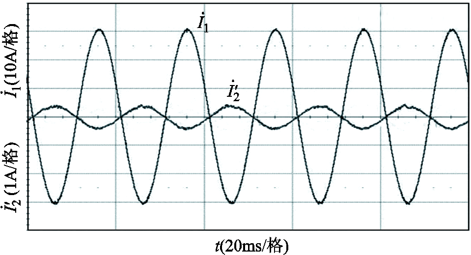
图10 电流波形
Fig.10 Current waveforms
由图10可知,补偿后的二次侧测量电流与一次电流相位相差接近。且利用电能质量分析仪可测得二次侧测量电流幅值为0.386A,故比差 。通过对比一次电流和二次侧测量电流的相位,可得出角差
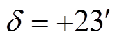 。可能导致测量误差的原因有:二次电流谐波、CT漏磁、绕组损耗、电阻电感等器件老化、开关电源对采样环节有噪声干扰等。但总体而言,磁平衡式CT仍有较高的测量精度。
本文提出了基于动态无功补偿技术的磁平衡式电流互感器设计方法,并对其工作原理进行了分析,提出了自适应扰动控制算法跟踪CT二次侧的最大电流,由理论推导到仿真分析与实验结果,可以得出所提出的磁平衡式电流互感器能准确地补偿CT中的励磁磁动势,实现大范围波动电流的实时监测,且其测量误差较小。
参考文献
[1] 李鹏, 黄新波, 赵隆, 等. 智能输电线路状态监测代理的研究与设计[J]. 中国电机工程学报, 2013, 33(16): 153-161.
Li Peng, Huang Xinbo, Zhao Long, et al. Research and design of transmission line condition monitoring agent[J]. Proceedings of the CSEE, 2013, 33(16): 153-161.
[2] 金能, 梁宇, 邢家维, 等. 提升配电网线路保护可靠性的远方保护及其与就地保护优化配合方案研究[J]. 电工技术学报, 2019, 34(24): 5221-5233.
Jin Neng, Liang Yu, Xing Jiawei, et al. Research on remote protection and the optimized coordination scheme of local-remote protection to enhance the protection reliability of the line in distribution network[J]. Transactions of China Electrotechnical Society, 2019, 34(24): 5221-5233.
[3] 任磊, 龚春英. 一种电力电子变换器功率 MOSFET 阈值电压在线监测方法[J]. 电工技术学报, 2018, 33(15): 3627-3634.
Ren Lei, Gong Chunying. An on-line monitoring method for threshold voltage of the power MOSFET in power electronic converters[J]. Transactions of China Electrotechnical Society, 2018, 33(15): 3627-3634.
[4] 张鹏, 王玮, 徐丙垠, 等. 基于自适应功率输出控制的电流互感器取能电源设计方法[J]. 电力系统自动化, 2020, 44(3): 194-200.
Zhang Peng, Wang Wei, Xu Bingyin, et al. Design method of energy-gaining power supply for current transformer based on self-adaptive power output control[J]. Automation of Electric Power Systems, 2020, 44(3): 194-200.
[5] 贺小艳. 降低电流互感器误差的措施分析[J]. 仪器仪表用户, 2019, 26(6): 23-25.
He Xiaoyan. Analysis of measures to reduce the error of current transformer[J]. Instrumentation, 2019, 26(6): 23-25.
[6] 刘杰, 裴杰, 田明, 等. 基于支持向量机的电流互感器非线性校正方法研究[J]. 电机与控制学报, 2020, 24(10): 130-138.
Liu Jie, Pei Jie, Tian Ming, et al. Research on nonlinear correction method of current transformer based on support vector machine[J]. Electric Machines and Control, 2020, 24(10): 130-138.
[7] 鲍海, 艾欣, 杨以涵. 双级零磁通电流互感器状态反馈控制研究[J]. 电工技术学报, 2000, 15(2): 12-14.
Bao Hai, Ai Xin, Yang Yihan. Research on states feedback control of two-stage zero flux current transformer[J]. Transactions of China Electrotechnical Society, 2000, 15(2): 12-14.
[8] 李培艳. 基于零磁通的无源单匝穿心式小电流互感器的研究[D]. 哈尔滨: 哈尔滨工业大学, 2006.
[9] 刘刚, 熊小伏, 廖瑞金, 等.泄漏电流对电流互感器误差特性的影响及分析[J]. 电工技术学报, 2018, 33(3): 697-704.
Liu Gang, Xiong Xiaofu, Liao Ruijin, et al. Effect and analysis of leakage current on error characteristics of current transformer[J]. Transactions of China Electrotechnical Society, 2018, 33(3): 697-704.
[10] 李华峰, 李苏楠, 张本锋. 压电作动器用无源可控电抗器及其动态补偿系统[J]. 中国电机工程学报, 2015, 35(5): 1237-1242.
Li Huafeng, Li Sunan, Zhang Benfeng. A dynamic compensation system of passive controllable reactor for piezoelectric actuator[J]. Proceedings of the CSEE, 2015, 35(5): 1237-1242.
[11] 单任仲, 尹忠东, 肖湘宁. 电压源型快速动态无功补偿器[J]. 中国电机工程学报, 2009, 29(24): 1-5.
Shan Renzhong, Yin Zhongdong, Xiao Xiangning. Rapidly dynamic var compensator based on voltage source converter[J]. Proceedings of the CSEE, 2009, 29(24): 1-5.
[12] 钱峰, 郑健超, 汤广福, 等. 利用经济压差确定动态无功补偿容量的方法[J]. 中国电机工程学报, 2009, 29(1): 1-6.
Qian Feng, Zheng Jianchao, Tang Guangfu, et al. New approach to determine capacity of dynamic reactive power compensation using economic voltage difference[J]. Proceedings of the CSEE, 2009, 29(1): 1-6.
[13] 刘文华, 宋强, 滕乐天, 等. 暂态电压稳定与新型动态无功补偿装置[J]. 电工技术学报, 2007, 22(7): 18-23.
Liu Wenhua, Song Qiang, Teng Letian, et al. Transient voltage stability and static synchronous compensator[J]. Transactions of China Electrotechnical Society, 2007, 22(7): 18-23.
[14] 武琳, 杨林, 姜远, 等. 一种改进的单相整流器控制策略研究[J]. 电机与控制学报, 2017, 21(11): 97-102.
Wu Lin, Yang Lin, Jiang Yuan, et al. Improved control strategy of single phase rectifier[J]. Electric Machines and Control, 2017, 21(11): 97-102.
[15] 黄铮, 杨大力. 一种变步长因子及变动量因子的自适应算法[J]. 北京邮电大学学报, 1994, 17(3): 90-94.
Huang Zheng, Yang Dali. An adaptive algorithm with a variable step and variable momentum factor[J]. Journal of Beijing University of Posts and Telecommunications, 1994, 17(3): 90-94.
[16] 丁浩, 魏艳君, 漆汉宏, 等. 基于自适应有功电流扰动的孤岛检测[J]. 电工技术学报, 2014, 29(8): 294-300.
Ding Hao, Wei Yanjun, Qi Hanhong, et al. A novel islanding detection based on adaptive active current disturbance[J]. Transactions of China Electrotechnical Society, 2014, 29(8): 294-300.
[17] 李振华, 田斌, 胡蔚中, 等. 基于变步长原理的改进型高精度数字积分算法[J]. 电力系统自动化, 2018, 42(2): 136-142.
Li Zhenhua, Tian Bin, Hu Weizhong, et al. Improved high-precision digital integral algorithm based on variable step principle[J]. Automation of Electric Power Systems, 2018, 42(2): 136-142.
[18] 王硕禾, 郑俊观, 张国驹, 等. 基于改进型变步长扰动观察法的光伏系统MPPT研究[J]. 广西大学学报(自然科学版), 2018, 43(3): 1032⁃1043.
Wang Shuohe, Zheng Junguan, Zhang Guoju, et al. MPPT study of photovoltaic system based on improved variable step-size perturb and observe algorithm[J]. Journal of Guangxi University(Natural Science Edition), 2018, 43(3): 1032-1043.
[19] Yüksek G, Mete A N. A hybrid variable step size MPPT method based on P&O and INC methods[C]//2017 10th International Conference on Electrical and Electronics Engineering (ELECO), Bursa, Turkey, 2017: 949-953.
[20] Zhang Chao, Zhao Dean, Wang Jinjing, et al. A modified MPPT method with variable perturbation step for photovoltaic system[C]//2009 IEEE 6th International Power Electronics and Motion Control Conference, Wuhan, China, 2009: 2096-2099.
[21] Wang Jilong, Li Shengmin. Research on PV maximum power point tracking based on improved perturbation and observation method[C]//2015 Chinese Automation Congress (CAC), Wuhan, China, 2015: 1344-1348.
[22] Liu Na, Zhang Demin. Research on MPPT control based on combined algorithm of perturbation observation[C]//2017 29th Chinese Control And Decision Conference (CCDC), Chongqing, China, 2017: 6989-6994.
[23] 刘建强, 刘传铎, 王轶欧, 等. 单相 PWM 整流器 IGBT 及直流侧电容故障诊断方法[J]. 电工技术学报, 2019, 34(增刊1): 244-257.
Liu Jianqiang, Liu Chuanduo, Wang Yiou, et al. Fault diagnosis method for IGBT and DC-link capacitor of single-phase PWM Rectifier[J]. Transactions of China Electrotechnical Society, 2019, 34(S1): 244-257.
[24] 刘博, 贲洪奇, 白银龙, 等. PWM 整流器轻载条件下网侧电流谐波分析与抑制[J]. 电工技术学报, 2016, 31(增刊1): 162-168.
Liu Bo, Ben Hongqi, Bai Yinlong, et al. Analysis and suppression of current harmonics in grid side of PWM rectifiers during light load[J]. Transactions of China Electrotechnical Society, 2016, 31(S1): 162-168.
[25] 魏川翔, 罗全明, 俎阿倩, 等. 一种有源电容变换器的分析与设计[J]. 电工技术学报, 2019, 34(12): 2539-2548.
Wei Chuanxiang, Luo Quanming, Zu Aqian, et al. Analysis and design of an active capacitor converter[J]. Transactions of China Electrotechnical Society, 2019, 34(12): 2539-2548.
Design of Flux Balanced Current Transformer Based on Dynamic Reactive Power Compensation Technology
Abstract A design method of flux balanced current transformer based on dynamic reactive power compensation technology is designed in the paper, and its application can achieve accurate measurement of a wide range of fluctuating current.Through the analysis of the working principle and measurement error of the current transformer, the control algorithm of the flux balance current transformer based on dynamic reactive power is proposed, that is, the maximum current tracking on the secondary side of the current transformer is realized by the adaptive disturbance method.Field-circuit coupling model of flux balance current transformer based on Comsol and Simulink co-simulation is established. The effectiveness of the proposed flux balance current transformer model and the feasibility of the control algorithm are verified by simulation and experiment.
keywords:Reactive power compensation, flux balanced current transformer, field-circuit coupling model,adaptive perturbation method
DOI:10.19595/j.cnki.1000-6753.tces.L90319
中图分类号:TM452
中央高校基本科研业务费专项资金资助项目(xzy012019025)。
收稿日期 2020-07-09
改稿日期 2020-10-10
国智博 男,1996年生,硕士研究生,研究方向为电力系统与电磁计算。E-mail:gzb1690607837@163.com
陈 锋 男,1979年生,副教授,博士生导师,研究方向为电力设备的优化设计和特性分析。E-mail:chenf@mail.xjtu.edu.cn(通信作者)
(编辑 崔文静)