Fig.1 Rotor structures of conventional PMASynRMs
Abstract The inherent feature of high efficiency over wide speed range positions permanent-magnet-assisted synchronous reluctance machine (SynRM) as an appealing contender for high-performance variable speed applications. Though the magnets are for assistance only, their characteristics have a significant effect on the machines, e.g., the rare-earth magnet encounters high cost and volatile supply chain issues while the ferrite one faces low energy product and demagnetization problems. This paper proposes a new hybrid PM-assisted SynRM by taking into consideration the effect from the large magnetic characteristic difference between the rare-earth and ferrite magnet materials. The anti-demagnetization capability of the machine can be significantly improved by allocating rare-earth magnets in the barriers adjacent to rotor outer periphery. Comprehensive analysis results have indicated an optimal ratio of slightly above 5% between rare earth and ferrite magnet volumes strikes a balance between the anti-demagnetization capability and the cost per Newton-Meter for such hybrid machine. A hybrid prototype with 5.5% rare-earth magnet volume ratio is designed to compare with its existing conventional counterparts which employ ferrite and rare-earth magnets individually. Both the finite element analysis and experimental results have revealed that all three machines have almost identical performance, but the hybrid machine has evidently enhanced the demagnetization withstanding capability over the ferrite PM-assisted SynRM and significantly reduced the magnet cost over the rare-earth one.
Keywords: Permanent-magnet-assisted synchronous reluctance machine, demagnetization, ferrite magnet, rare-earth magnet, hybrid effect
With the ever-increasing energy consumption, electric machines which use up half the electricity produced globally have been relentlessly in quest for high efficiency[1]. Due to the distinctive merits of low cost and robust structure, induction machines have been widely deployed for variable-speed applications such as pump units. However, induction machines are well recognized to normally have lower efficiency than their synchronous counterparts in such applications[2]. The nature of the variable-speed applications require the machine drive with characteristics of low cost, robustness, and high efficiency over wide operational speed range[3-5]. Therefore, synchronous reluctance machine (SynRM) is a potential candidate for such applications thanks to its various merits such as robust rotor structure, low rotor loss, simple manufacture, low cost and high temperature tolerance[6-7]. However, SynRM suffers from its demerits such as inferior torque density, low power factor and efficiency.
With the assistance from a fair amount of permanent magnet, the machine turns into permanent-magnet-assisted synchronous reluctance machine (PMASynRM) and the performance can be significantly improved[8-13]. The inherent distinctive features make PMASynRM a strong contender for variable-speed applications. The rare-earth PMASynRM has been widely examined to have excellent efficiency, high power density, and strong anti-demagnetization ability[9-10, 14-17]. However, the high cost and volatile supply chain issues of the rare-earth magnet material have hindered the extensive deployment of such machine in variable-speed applications. An alternative solution is to adopt low-cost and abundant ferrite magnet in PMASynRM to achieve very similar performance as rare-earth one[18-23]. Howbeit, the poor magnetic property of the ferrite magnet brings about potential demagnetization problems in such machine[24-25]. Ferrite magnet with stronger magnetic characteristics and high cost is employed to enhance the demagnetization withstanding capability[26].
On the other hand, hybridization of ferrite and rare-earth magnets has been extensively investigated and employed to minimize the cost of interior permanent magnet synchronous machines (IPMSMs) by maintaining the same performance level as rare-earth one[27-32]. As the magnetic characteristics of ferrite and rare-earth magnets are of great difference, the rotor magnetic circuit topology has to be carefully elaborated in order to avoid irreversible demagnetization of the ferrite material from the strong magnetic field generated by rare-earth material[30]. Generally, there are three main hybrid arrangements of the magnetic sources from ferrite and rare-earth magnets in the rotor magnetic circuit: series, parallel, and combination of series and parallel. The permanent magnet (PM) flux level in such machine with series configuration which is normally limited by the ferrite magnets, is relatively low and quite challenging to match the one in rare-earth machine. As a consequence, parallel configurations of ferrite and rare-earth magnetic sources are mostly implemented in hybrid IPMSMs so that reasonable PM flux and hence high performance can be achieved. However, the existence of parallel configuration can easily cause irreversible demagnetization of the ferrite magnets in the stand-alone rotor. As a consequence, either the assembly of such machine becomes cumbersome and costly, or the design options of rotor structure are very limited.
However, PMASynRMs normally require relatively low PM flux level thanks to its high rotor saliency so that series configurations of ferrite and rare-earth magnetic sources can be comfortably put into practice. This paper proposes a new hybrid PMASynRM with both ferrite and rare-earth magnets to address the aforementioned issues of the conventional PMASynRMs for variable-speed applications by utilizing the strong magnetic property of the rare-earth magnet and low cost of ferrite magnet. In SectionⅠ, two existing conventional PMASynRMs with sole ferrite and rare-earth magnet materials for variable-speed pump application are introduced and the pros and cons of such machines are properly appraised. In SectionⅡ, a comprehensive investigation of a hybrid PMASynRM topology with series configuration has been carried out to reveal a general design guideline for such machine and a hybrid PMASynRM is readily designed to achieve high demagnetization withstanding capability as well as low magnet cost, and the performance comparisons between the newly designed hybrid PMASynRM with the two existing conventional counterparts are readily presented. Furthermore, in Section Ⅲ, comprehensive experimental results are presented to validate that the proposed hybrid PMASynRM can deliver very similar performance with the right balance between the anti-demagnetization ability and material cost, followed by concluding remarks in Section Ⅳ.
The distinctive merits of PMASynRM lend itself a strong contender for variable-speed applications. Two conventional PMASynRM prototypes with mere ferrite and rare-earth magnet materials are designed and produced for variable-speed application. The integral-slot configuration is of particular preference in such machine type to minimize the spatial harmonic leakages and maximize the machine saliency. The torque density of the machine generally increases along with the slot number per phase per pole (q). However, excessive q number will complicate the stator geometry and make manufacture cumbersome and even impractical. Hence, q=3 is chosen for the proposed two PMASynRMs. On the other hand, the main linkage inductances are about reverse-proportional to the square of rotor pole pair number (p) while the leakage inductances are nearly reverse-proportional to a value between p and its square value. Consequently, the percentage of the leakage inductance over the whole inductance will be aggrandized and hence the saliency of the machine attenuates as p increases[33]. By taking all these aspects into account, the prototypes employ 36 stator slots and 4 rotor poles.
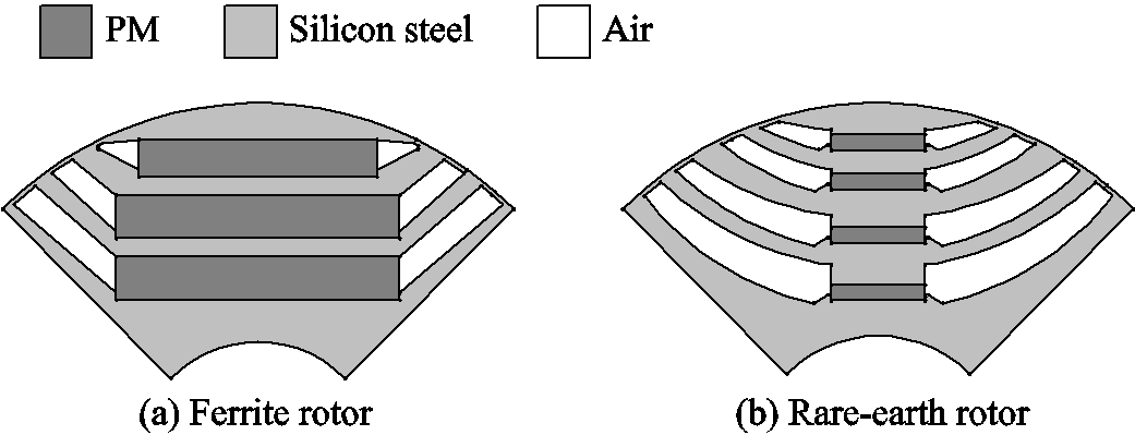
Although the two prototypes adopt different magnet materials, they are designed to have almost identical performance. The rotor structures of the prototypes are depicted in Fig.1, and the main design parameters of the prototypes are given in Tab.1. The identical stators with single-layer short-pitch two prototypes share the same envelope and have distributed windings. On the other hand, the prototypes employ three and four flux barriers in the rotors to accommodate the corresponding thick and wide ferrite, thin and narrow rare-earth magnets, respectively. The rotors are elaborately designed to achieve very similar air-gap flux density and rotor saliency despite the huge geometrical difference, the characteristics of the prototypes are very close.
Fig.1 Rotor structures of conventional PMASynRMs
Tab.1 Main parameters of the PMASynRM prototypes
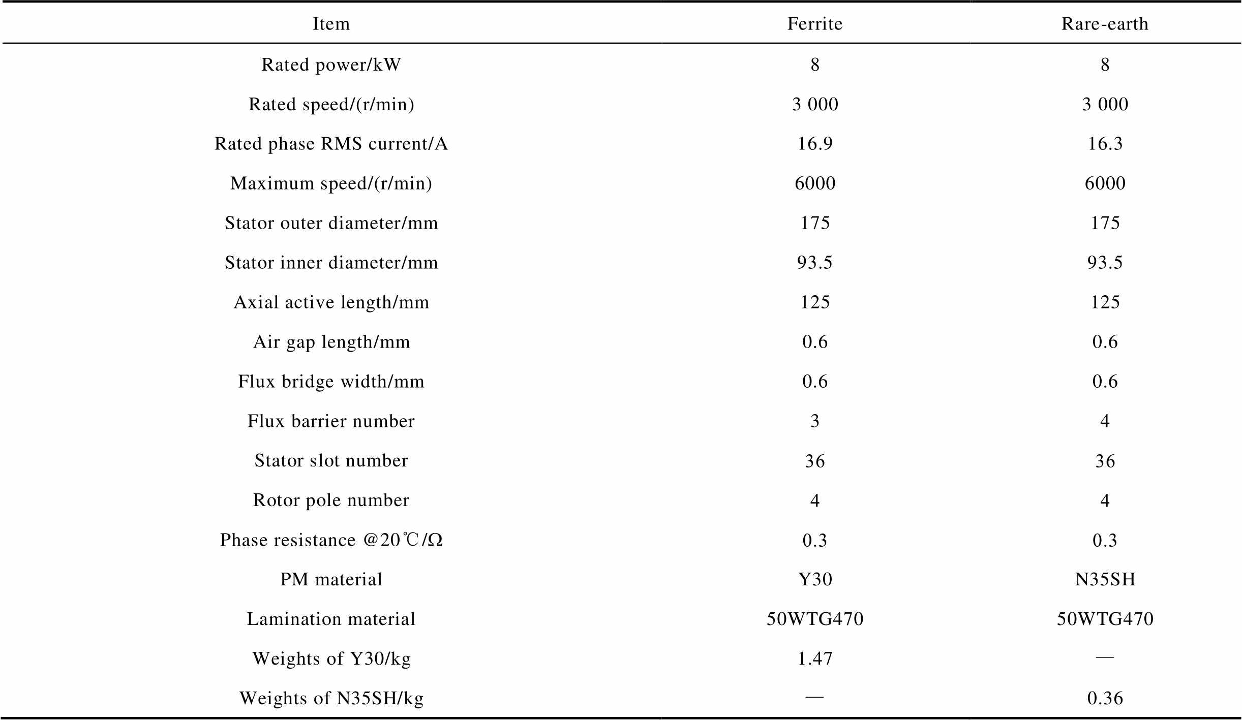
ItemFerriteRare-earth Rated power/kW88 Rated speed/(r/min)3 0003 000 Rated phase RMS current/A16.916.3 Maximum speed/(r/min) 60006000 Stator outer diameter/mm175175 Stator inner diameter/mm93.593.5 Axial active length/mm125125 Air gap length/mm0.60.6 Flux bridge width/mm0.60.6 Flux barrier number34 Stator slot number3636 Rotor pole number44 Phase resistance @20℃/W0.30.3 PM materialY30N35SH Lamination material50WTG47050WTG470 Weights of Y30/kg1.47— Weights of N35SH/kg—0.36
The 2-D mechanical FEA is carried out to evaluate the Von Mises stress distributions on the rotors at the maximum rotational speed of 6 000r/min, and the results is illustrated in Fig.2. It shows that the maximum stress occurs on the circumferential bridges of the innermost flux barrier for both rotors and the values are well under the maximum allowable stress of the lamination material 50WTG470. The integrity of the rotors against the centrifugal force at maximum rotational speed has been confirmed. The root-mean-square (RMS) values of the phase current at rated-load condition are 16.9A and 16.3A, respectively for the prototypes with ferrite and rare-earth magnets. Comprehensive 2-D magnetic FEA simulations are implemented to reveal and compare the performances of the two prototypes. The maximum-torque-per-ampere (MTPA) traces of the machines are derived and shown in Fig.3, in which the current values are normalized to the respective rated currents. It can be observed from the figure that the traces of the two machines are nearly identical as the prototypes have very close PM flux level and saliency. Moreover, the efficiency maps over the operational envelope of the two prototypes are compiled and illustrated in Fig.4, which shows both machines operate with above 90% efficiency over most of the operational range. It unequivocally underpins the suitability of PMASynRM for high-performance variable-speed applications. It can be found from the figure that the rare-earth machine has somewhat greater efficiency than the ferrite counterpart due to its slightly higher torque coefficient.
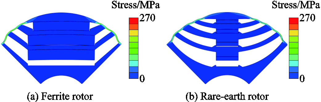
Fig.2 Rotor von mises stress distributions at maximum speed
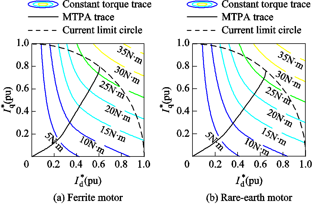
Fig.3 MTPA traces of prototypes
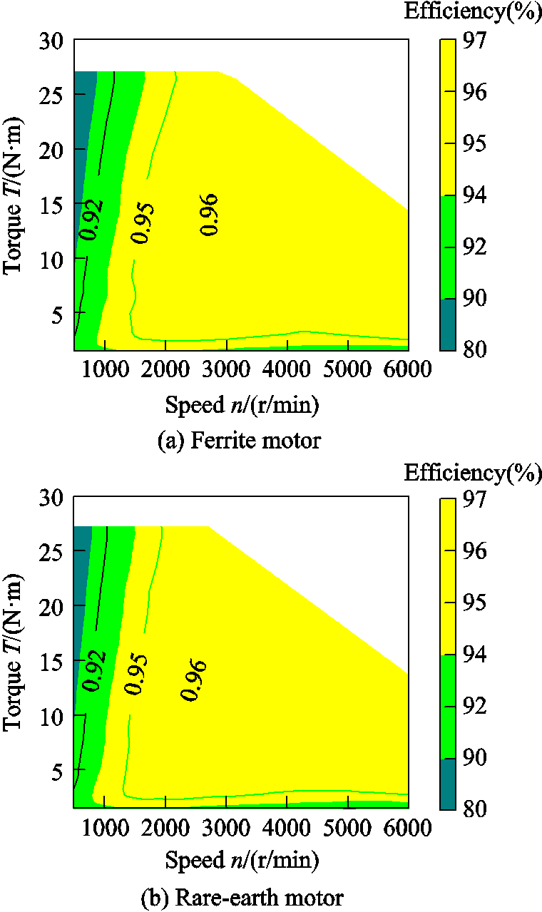
Fig.4 Efficiency maps of prototypes
Furthermore, the demagnetization rate as a function of the phase current with PMs in different flux barriers for both prototypes are evaluated by 2-D magnetic FEA. In the analysis, the phase current ranges from 2 to 3.2 times the rated phase current with the current phase angle which turns the armature reaction magnetic field fully against the PM magnetic field. Without loss of generality, it is assumed the PM temperature range during operation is from 0℃ to 100℃considering the particular application of the machines. In order to consider the worst case scenario of demagnetization, the temperature of ferrite and rare-earth magnets during analysis are set as 0℃ and 100oC, respectively. The results reveal that no demag-netization occurs in the rare-earth PMASynRM prototype with the proposed current and temperature ranges. Whilst, the ferrite PMASynRM prototype suffers severe demagnetization in general as shown in Fig.5a. The total demagnetization rate reaches 35.4% with the PM temperature of 0℃ as the phase current runs up to 3.2 times the rated one. The ferrite PM in the outermost flux barrier suffers the most serious demagnetization issue while the one in the innermost flux barrier has the best demagnetization withstanding capability. As the phase current increases, the demagnetization rate of ferrite PM in outermost flux barrier gradually rises, and starts to increase sharply after 2.3 times the rated current to nearly 10% at 2.5 times the rated current, annotated as stageⅠ in Fig.5a, then maintains flat till 2.9 times the rated current as stageⅡ, after which it grows again as stage Ⅲ. There are two contribution factors for demagnetization during stageⅠ. First, the PM fluxes flow primarily through the circumferential flux brides[8]. The edges of magnet have smaller reluctance than the middle section so that they are more susceptible to magnetization. Second, the armature-reaction fluxes run through the outermost flux barrier mainly in two paths shown as A and B in Fig.5b. Path A has much lower reluctance than Path B so that demagnetization expands rapidly in the PM edge area as current rises in stageⅠ. At the beginning of stageⅡ, most of the PM edge area has been irreversibly demagnetized and the armature-reaction magnetic field are not strong enough to overcome the larger reluctance for middle section demagnetization. In stageⅢ, critical point has been exceeded with the ever-increasing current and the middle section starts demagnetization. The demag-netization characteristics of ferrite PMs in other flux barriers follow the same pattern merely with larger phase current.
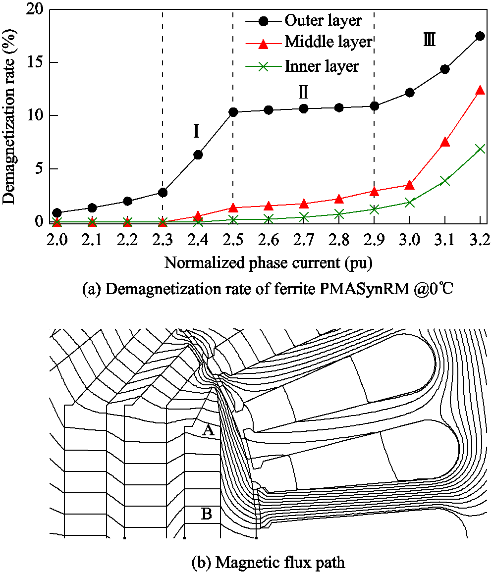
Fig.5 Demagnetization rate characteristics of ferrite PMASynRM prototype
The experimental tests under rated load condition are carried out with both PMASynRM prototypes for four hours and the temperature rises of the PMASynRM cases are 38.6℃ and 35.3℃ for ferrite and rare-earth prototypes, respectively. The difference between the temperature rises are somewhat larger than expected as the rated efficiency of the two prototypes are nearly the same shown in Fig.4. The phase current waveforms are constantly monitored during the tests for both machines and the discrepancy between the waveforms at the beginning and finishing of the tests for ferrite prototype is quite evident. Occurrence of demagnetization in ferrite prototype is suspected. Therefore, the measured phase back electromotive forces (EMFs) before and after the experimental tests are compared and shown in Fig.6 for both prototypes. In order to show the changes of waveforms before and after the experiment clearly, the Back-EMF with different starting positions is intercepted. It reveals that the fundamental phase back EMF values of both machines at 600r/min are very close before the rated experimental tests, 19.5V and 20.1V for ferrite and rare-earth prototypes, respectively. However, the corresponding fundamental back EMF value of the ferrite prototype drops by 47.7% to 10.2V after the test while the rare-earth one keeps unchanged. Although the demagnetization analysis of the ferrite PMASynRM prototype shows there are hardly demagnetization at rated current condition, the experi-mental results confirm irreversible demagnetization. Demagnetization is intolerable in practice and becomes apparently a critical issue for ferrite PMASynRM. On the other side, rare-earth PMASynRM has much stronger demagnetization withstanding capability but the material cost and supply chain volatility are also formidable problems. Consequently, it is of practical necessity to form a scheme which can resolve these issues.
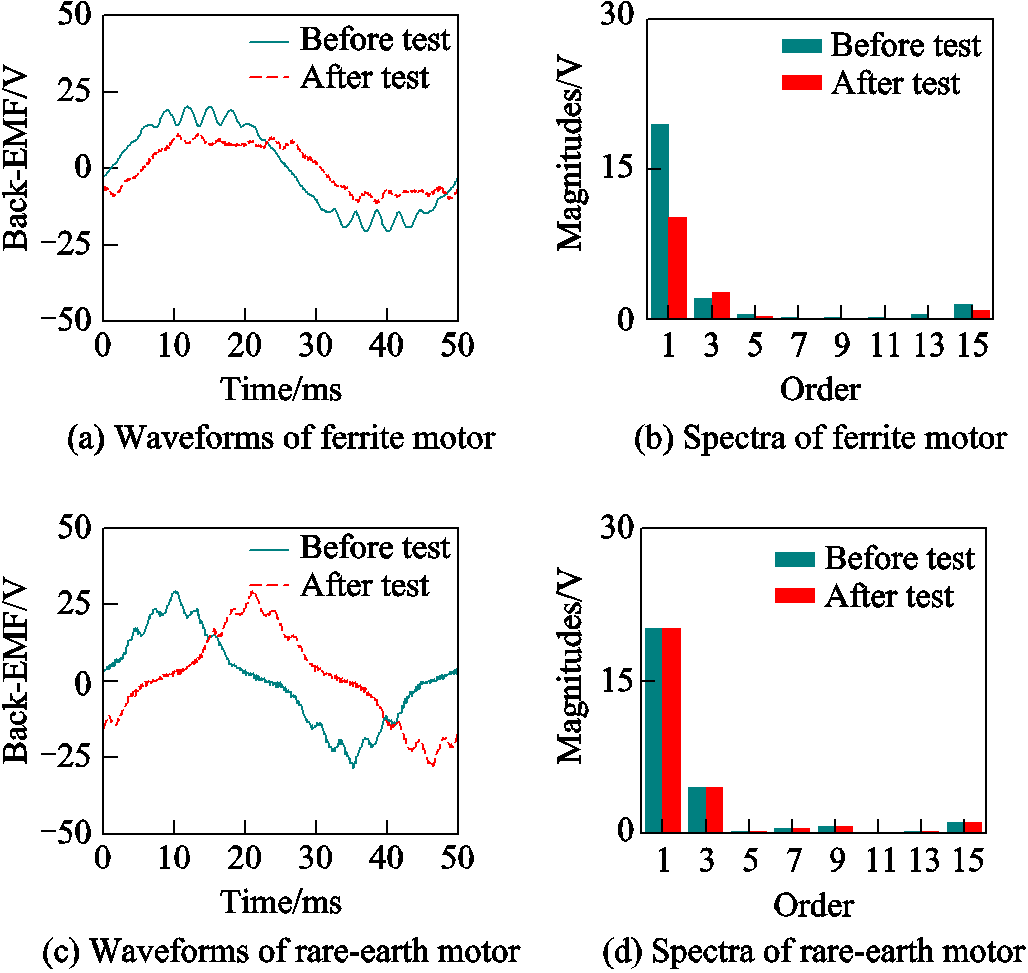
Fig.6 Experimental phase back EMF waveforms and spectra of PMASynRM prototypes at 600r/min
Hybrid PMASynRM with both ferrite and rare-earth PM material is a feasible solution to improve anti-demagnetization capability and minimize material cost. Thus, such option has been explored and a new hybrid PMASynRM is designed to match the two aforementioned conventional counterparts. The new machine will deliver nearly identical electromagnetic performance with the same stator, air-gap length, and flux bridge width. The goal is to minimize the rare-earth PM volume but still deliver similar demagnetization withstanding capability as its rare-earth counterpart. Since the ferrite PM in the outermost flux barrier is the most vulnerable to irreversible demagnetization as shown in Fig.5a, it is equitable to form a series hybridization by replacing it with rare-earth PM. As a result, the new rotor has exactly the same middle and innermost flux barriers together with ferrite PMs as the ferrite one.
As the magnetic properties of ferrite and rare-earth PMs are of wide difference, severe local saturations which reduce rotor saliency and lead to performance deterioration, can potentially occur in the rotor. Therefore, the width of the rare-earth PM needs special attentions. The magnetic flux path in such hybrid configuration with open-circuit and load conditions are depicted in Fig.7. As the magnetic field inside rare-earth PM is much stronger than the one inside ferrite PM, the outermost flux barrier tends to accommodate more magnetic fluxes than the other two under open-circuit condition as shown in Fig.7a. As a result, there are noticeable magnetic fluxes through region A and A' but hardly magnetic fluxes in region D and D'. Moreover, the magnetic fluxes under the edges of rare-earth PM in region B and B' are bent and distinct from the ones in region C and C' due to the different widths between rare-earth and ferrite PMs. Such phenomena incur potential severe magnetic saturations in region A and B (A' and B') as the armature-reaction magnetic field rises under load conditions as shown in Fig.7b. The magnetic fluxes in region D and D' are mostly contributed by the armature-reaction magnetic field and almost the same. Whilst, there are apparently more magnetic fluxes in region A and B than the respective region A' and B'. As a result, region A and B have much higher tendency towards severe magnetic saturations, which will reduce machine saliency, introduce cross-coupling effect between direct- (d-) and quadrature- (q-) axes, and hence degrade the machine performance. In order to alleviate such hybrid effect, some general design guidelines can be introduced. The magnetic fluxes induced by the rare-earth PM should be very close to that by the ferrite PM so that a downward tendency of magnetic saturation in position A and A' can be achieved. Furthermore, thin and wide rare-earth PM are preferred to reduce the saturation tendency in region B and B'. However, thin PM will reduce the corresponding reluctance of the flux barrier and increase the risk of magnetic saturations in region A, A' B, and B' in general so that the reluctance torque decreases. Moreover, exceedingly thin PM can also risk manufacturablity. So the rare-earth PM in the outermost flux barrier in the proposed new hybrid PMASynRM has the same thickness of 2mm as the rare-earth one.
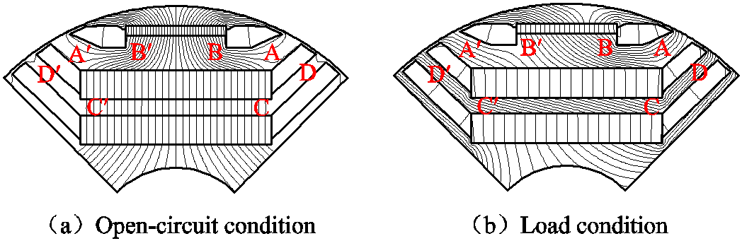
Fig.7 Magnetic flux path in hybrid PMASynRM rotor
The influences of the rare-earth PM width on electromagnetic performances with particular emphasis on torque characteristics and demagnetization withstanding capability are comprehensively investigated by 2-D magnetic FEA for the proposed new hybrid PMASynRM. With the rated phase current (RMS value 16.6A) excitation, the corresponding current phase angles are obtained through extensive simulations for the machines with different PM widths to achieve MTPA operations. The resultant overall torque values with their compositions of reluctance and PM torque values are compiled and illustrated with the magnet widths in Fig.8a. It can be observed from the figure that the reluctance torque is the dominant component compared with the PM one as expected. The PM torque gradually increases as the rare-earth PM widens, while the reluctance torque first mildly inclines to reach its maximum at PM width of around 10mm and then start to gradually declines. Overall, the total electromagnetic torque gently rises along with PM width. Furthermore, the demagnetization analysis of the machines with different PM widths are carried out with 3.2 times the rated phase current with the current phase angle which turns the armature reaction magnetic field fully against the PM magnetic field. The results show that there is no demagnetization in the rare-earth PM in outermost flux barrier, and the demagnetization rates of the ferrite PMs are obtained and plotted with rare-earth PM widths in Fig.8b. The demagnetization rate declines sharply at first and reaches nearly 0 at width of 17mm and then start to slightly increases and gradually decreases as the rare-earth PM width increases. The rare-earth PM width of 12mm is chosen for the proposed new hybrid PMASynRM to achieve an appropriate balance of torque performance, anti-demagnetization capability, and cost. The rotor structure of the newly designed hybrid PMASynRM is shown in Fig.9a, while the Von Mises stress distribution on the rotor at maximum rotational speed from 2-D mechanical FEA is illustrated in Fig.9b. It can be observed the stress distributions are very close to the conventional ferrite and rare-earth PMASynRM prototypes in Fig.2. It is noteworthy that the rated phase current RMS value of the hybrid machine is 16.6A. The demagnetization rate profiles of the PMs in different flux barriers with the phase current ranged from 2 to 3.2 times the rated one at 0℃ and 100℃ is derived. There is no demagnetization occurs at 100℃ in the rare earth permanent magnet, while the demagnetization rate at 0℃is shown in Fig.10a. It has revealed that the hybrid prototype has significantly improve the anti-demagnetization ability compared with the ferrite one in Fig.5a. The MTPA trace of the hybrid PMASynRM prototype is derived and depicted in Fig.10b. By comparing with Fig.3, the MTPA traces of the three prototypes are very close and nearly identical, which indicates they deliver similar PM, reluctance, and overall torque values. The efficiency map of the hybrid prototype over the operational envelope is also derived and shown in Fig.10c. The efficiency map in the figure shows very similar results as Fig.4.
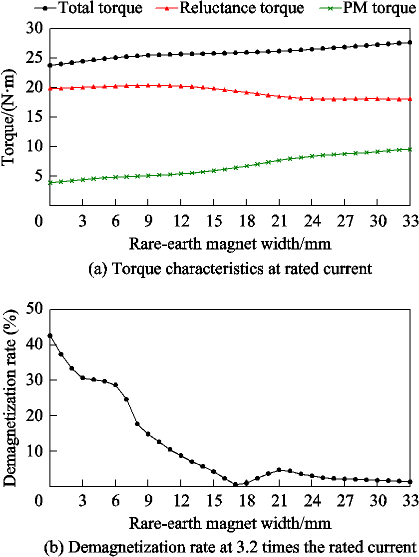
Fig.8 Influences of rare-earth PM width on performances of new Hybrid PMASynRM
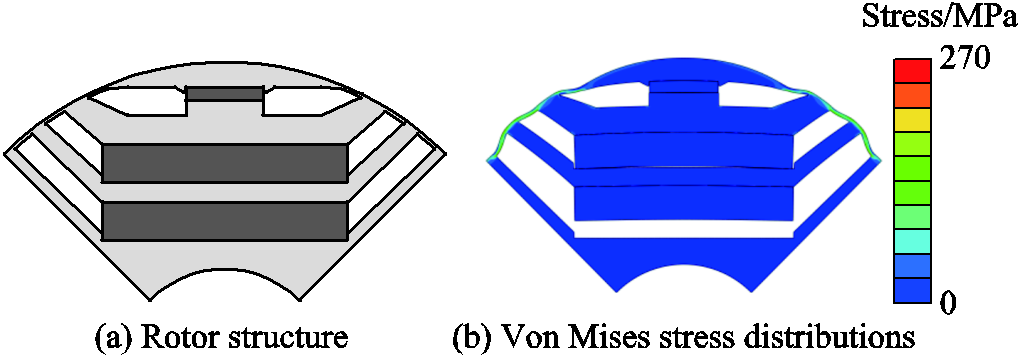
Fig.9 Rotor structures of new hybrid PMASynRM and Von Mises stress distribution in the rotor at 6 000r/min
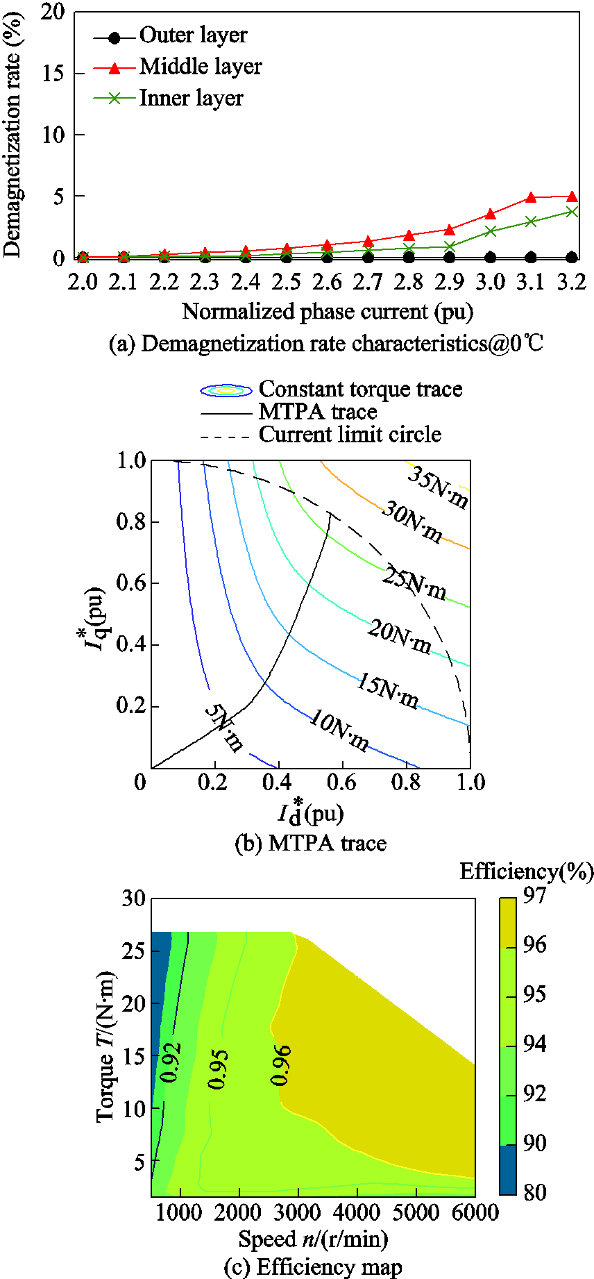
Fig.10 Electromagnetic performances of new hybrid PMASynRM
Since the three machines share the identical stator, the weight of the stator copper wires is exactly the same. Moreover, the three prototypes have similar lamination weights. On the other hand, the rare-earth N35SH material currently is almost 15 times more expensive than the ferrite Y30 in terms of cost per kilograms. Moreover, the price of the rare-earth materials used in N35SH are constantly fluctuating while the ferrite price is relatively very stable. The ferrite PMASynRM prototype has the lowest material cost, and rare-earth one suffers the highest cost. The weights of Y30 and N35SH in the newly proposed hybrid PMASynRM prototype is 1.08kg and 0.09kg, respectively. The hybrid PMASynRM reduces the rare-earth PM usage by 75% compared with the conventional rare-earth counterpart. All the aforementioned results have confirmed the hybrid solution a very promising alternative.
The PMASynRM prototypes with three different rotor configurations are built for experimental validations of the FEA results. Fig.11 shows the photos of the wound stator and three proposed rotors. The experimental setup of the test rig for load experiments is shown in Fig.12, in which a torque sensor sandwiched by the tested prototype PMASynRM and the load machine can provide accurate torque measurement on the shaft. The load machine is controlled by programmable controller to deliver desired load. The prototype machines are powered by an off-the-shelf commercial three-phase voltage-source-inverter (VSI) drive with space vector pulse-width-modulation (SVPWM) technique. Similarly, the experimental test on the new hybrid under rated load condition of 8kW power output at 3 000r/min is performed for four hours and temperature rise of the stator case is 36.2℃ which is quite close to the rare-earth prototype. The phase back EMF waveforms of the hybrid prototype before and after such load test are measured at rotational speed of 600r/min and illustrated together with their spectra in Fig.13. The phase back EMF keeps unchanged before and after the rated load endurance test, which indicates there is no irreversible demagnetization occurring in the hybrid prototype. The fundamental component of the phase back EMF of the new hybrid prototype at 600r/min is 20.2V, which is very close to the ones of the ferrite and rare-earth counterparts. An astounding improvement on demagnetization withstanding capability has been achieved and experimentally confirmed for the new hybrid PMASynRM over its conventional ferrite counterpart.
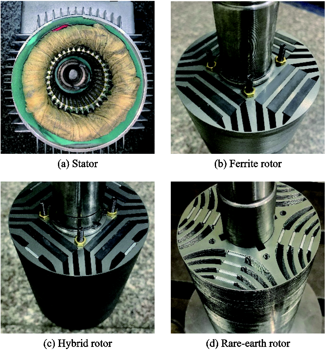
Fig.11 Stator and rotors of three PMASynRM prototypes under tests

Fig.12 Experimental setup
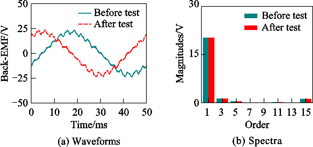
Fig.13 Experimental phase back EMF waveforms and spectra of hybrid PMASynRM prototype at 600r/min
Furthermore, extensive experiments have been carried out on the proposed three prototypes to validate the simulation results and compare the performances. In order to avoid unexpected potential demagnetization in ferrite PMASynRM prototype, all the three prototypes are excited with half the rated phase current and different current phase angles and the rotational speeds are regulated at 3000r/min by the speed controller. The corresponding output torque waveforms are measured and their average values are derived and plotted versus the current phase angle together with the FEA results in Fig.14 for all three machines. It can be found from the figure that the output torque versus the current phase angle of three machines follows the same profile from both simulation and experimental results. All three machines reach their MTPA operations at current phase advanced angle of about 40 electrical degrees and deliver very close output torque values. The simulation results slightly overestimate the output torque values with the maximum prediction errors near the MTPA region. The maximum discrepancies are 2.4%, 3.5%, and 2.8% for ferrite, hybrid, and rare-earth prototypes, respectively. With the MTPA and flux weakening (modulation index reaches its maximum) control scheme, three prototypes are excited with phase current values ranged from 0 to 1.2 times the rated value at the rated speed of 3 000 r/min. The output torque characteristics are captured by the accurate torque sensor and the resultant average torque values are compiled with different current values and depicted in Fig.15, which shows the three machines have very similar torque output characteristics versus phase current and reaches their maximum torque constants near rated current conditions. The experimental results are noticeably smaller than the predicted ones as the current gets larger, but the discrepancies are still quite mild. The measured average output torque values of the ferrite, hybrid, and rare-earth PMASynRM prototypes are 25.08N∙m, 25.04N·m, and 25.01N·m, respectively. The corresponding estimate errors are 2.1%, 2.6%, and 2.6%. Moreover, the experimental tests on the three prototypes with the rated current and MTPA and flux weakening (modulation index reaches its maximum) control scheme are performed with different rotational speeds from 300r/min to 3 000r/min. Both the output and input powers are captured and the efficiencies are obtained and compared with the simulation results in Fig.16. Again, the figure reveals the three machines have very close characteristics of high efficiency in general. As the stator winding copper losses are the dominant one of the machines operating below rated speed, the efficiencies increase as the speeds pick up. The efficiencies of the ferrite, hybrid, and rare-earth PMASynRM prototypes under rated condition are 93.6%, 94.0%, and 94.3%, respectively, indeed very close. It comports quite well with that the ferrite prototype has the largest rated current while the rare-earth one enjoys the smallest rated current. The corresponding differences between simulation andexperimental results are 2.0%, 1.6%, and 1.7%. It is noteworthy that the mechanical frictional loss and stray loss are not included in the simulation results.
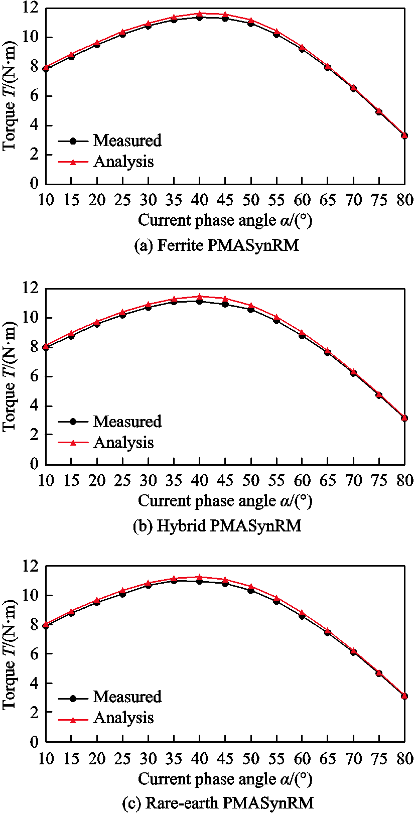
Fig.14 Torque output versus current phase angle of three prototypes with half the rated current at 3 000r/min
The simulation results presented are derived from the 2-D FEA simulations which do not account for the manufacture tolerance and material property defects. More importantly, the end effects are inherently neglected in the simulations. Taking the aforementioned factors into account and allowing for errors due to measurement and instrumentation, the agreements between the predicted and measured results are considered very well. Overall, the three proposed PMASynRM prototypes have very close performances, the new hybrid machine has shown very appealing anti-demagnetization capability over its ferrite counterpart and effective cost reduction on its rare-earth counterpart. The experimental results have underpinned that the hybrid PMASynRM is well suited for high-performance variable-speed applications.
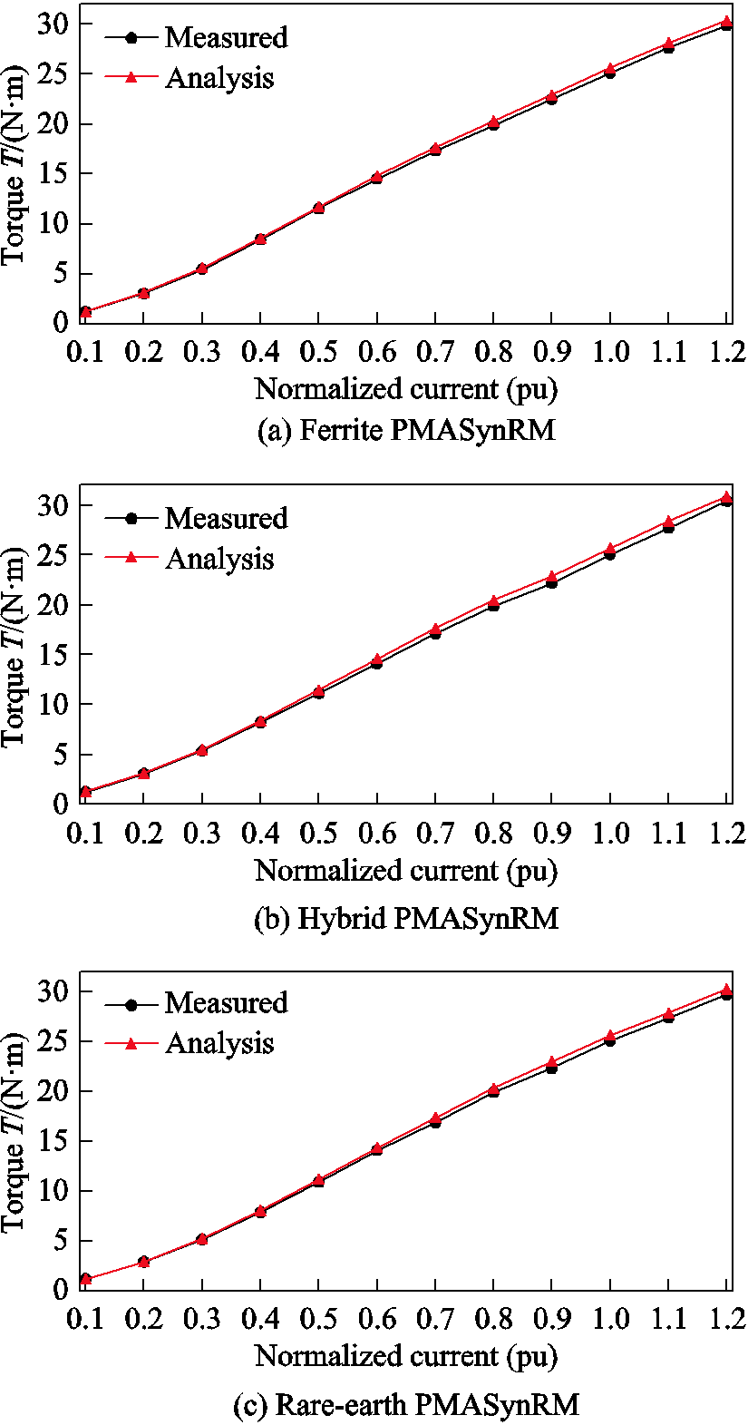
Fig.15 Torque output versus phase current of three prototypes with MTPA and flux weakening control scheme at 3 000r/min
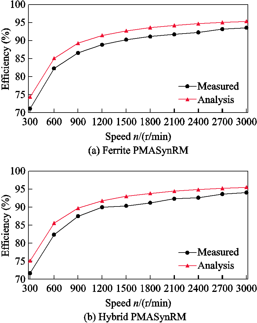
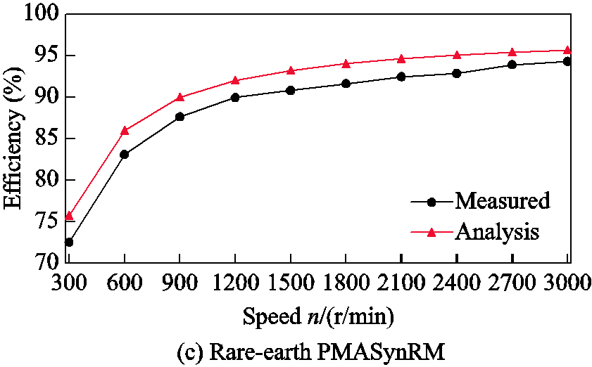
Fig.16 Machine efficiencies versus operational speed of three prototypes with the rated current and MTPA and flux weakening control scheme
A new hybrid PMASynRM with series configuration is proposed in this paper to overcome the demagnetization issue of ferrite one and meantime resolve the high cost matter of rare-earth one. The demagnetization withstanding capability can be drastically improved by replacing the ferrite PMs in the flux barriers close to the rotor outer periphery with rare-earth ones while the performance of the machine still keeps the same. The width and thickness of the rare-earth PMs in the hybrid machine ought to be carefully designed to balance the manufacturability, anti-demagnetization ability, and cost. Both the simulation and experimental results have confirmed that the new hybrid machine have nearly the same performance as the conventional ferrite and rare-earth ones with enhanced demagnetization withstanding capability over ferrite counterpart and reduced cost compared with rare-earth counterpart. Finally, it can be envisaged from the experimentally validated performance results that the PMASynRM with such hybrid configuration can be widely deployed for high-performance variable-speed applications.
Reference
[1] Bose B K. Global warming: energy, environmental pollution, and the impact of power electronics[J]. IEEE Industrial Electronics Magazine, 2010, 4(1): 6-17.
[2] Boztas G, Aydogmus O, Caner M, et al. Design, optimisation and implementation of low-voltage synchronous reluctance motor for solar-powered systems[J]. IET Power Electronics, 2019, 12(7): 1679-1685.
[3] Gedıkpinar M. Design and implementation of a self-starting permanent magnet hysteresis synchronous motor for pump applications[J].IEEE Access, 2019, 7: 186211-186216.
[4] Bottauscio O, Casaro F, Chiampi M, et al. High-speed drag-cup induction motors for turbo-molecular pump applications[J]. IEEE Transactions on Magnetics, 2006, 42(10): 3449-3451.
[5] Miah M S. Fault-tolerant BLDC motor-driven pump for fluids with unknown specific gravity: an experimental approach[J]. IEEE Access, 2020, 8: 30160-30173.
[6] Kim K C, Ahn J S, Won S H, et al. A study on the optimal design of SynRM for the high torque and power factor[J]. IEEE Transactions on Magnetics, 2007, 43(6): 2543-2545.
[7] Xu Xinyuan, Wang Yunchong, Shen Jianxin. Direct torque control-space vector modulation control strategy of synchronous reluctance motor based on maximum torque per-ampere[J]. Transactions of China Electrotechnical Society, 2020, 35(2): 246-254.
[8] Sun Yi, Lin Yingqian, Cai Shun, et al. Active saturation method for rotor magnetic bridges in synchronous reluctance machines[C]//2018 21st International Conference on Electrical Machines and Systems (ICEMS), Hamamatsu, Japan, 2018: 21-26.
[9] Niazi P, Toliyat H A, Goodarzi A. Robust maximum torque per ampere (MTPA) control of PM-assisted SynRM for traction applications[J]. IEEE Transactions on Vehicular Technology, 2007, 56(4): 1538-1545.
[10] Armando E, Guglielmi P, Pellegrino G, et al. Accurate modeling and performance analysis of IPM-PMASR motors[J]. IEEE Transactions on Industry Applications, 2009, 45(1): 123-130.
[11] Wang Jin, Li Yan, Jia Jianguo, et al. Analysis of the influence of back-EMF and saliency ratio on steady-state characteristics of a high efficiency permanent magnet synchronous reluctance motor[J]. Transactions of China Electrotechnical Society, 2020, 35(22): 4688-4698.
[12] Barcaro M, Pradella T, Furlan I. Low-torque ripple design of a ferrite-assisted synchronous reluctance motor[J]. IET Electric Power Applications, 2016, 10(5): 319-329.
[13] Yang Chen, Bai Baodong, Chen Dezhi, et al. Design and analysis of a variable flux permanent magnet assisted synchronous motor[J]. Transactions of China Electrotechnical Society, 2019, 34(3): 489-496.
[14] Guglielmi P, Boazzo B, Armando E, et al. Permanent-magnet minimization in PM-assisted synchronous reluctance motors for wide speed range[J]. IEEE Transactions on Industry Applications, 2012, 49(1): 31-41.
[15] Boldea I, Tutelea L, Pitic C I. PM-assisted reluctance synchronous motor/generator (PM-RSM) for mild hybrid vehicles: electromagnetic design[J]. IEEE Transactions on Industry Applications, 2004, 40(2): 492-498.
[16] Bonthu S S R, Arafat A K M, Choi S. Comparisons of rare-earth and rare-earth-free external rotor permanent magnet assisted synchronous reluctance motors[J]. IEEE Transactions on Industrial Electronics, 2017, 64(12): 9729-9738.
[17] Maroufian S S, Pillay P. Design and analysis of a novel PM-assisted synchronous reluctance machine topology with AlNiCo magnets[J]. IEEE Transactions on Industry Applications, 2019, 55(5): 4733-4742.
[18] Ooi S, Morimoto S, Sanada M, et al. Performance evaluation of a high-power-density PMASynRM with ferrite magnets[J]. IEEE Transactions on Industry Applications, 2013, 49(3): 1308-1315.
[19] Huang H, Hu Y S, Xiao Y, et al. Research of parameters and antidemagnetization of rare-earth-less permanent magnet-assisted synchronous reluctance motor[J]. IEEE Transactions on Magnetics, 2015, 51(11): 1-4.
[20] Morimoto S, Ooi S, Inoue Y, et al. Experimental evaluation of a rare-earth-free PMASynRM with ferrite magnets for automotive applications[J]. IEEE Transactions on Industrial Electronics, 2014, 61(10): 5749-5756.
[21] Obata M, Morimoto S, Sanada M, et al. Performance of PMASynRM with ferrite magnets for EV/HEV applications considering productivity[J]. IEEE Transactions on Industry Applications, 2013, 50(4): 2427-2435.
[22] Zhao Wenliang, Chen Dezhi, Lipo T A, et al. Performance improvement of ferrite-assisted synchronous reluctance machines using asymmetrical rotor configurations[J]. IEEE Transactions on Magnetics, 2015, 51(11): 1-4.
[23] Liu Huaicong, In-Gun Kim, Ye Jun Oh, et al. Design of permanent magnet-assisted synchronous reluctance motor for maximized back-EMF and torque ripple reduction[J]. IEEE Transactions on Magnetics, 2017, 53(6): 1-4.
[24] Cai Haiwei, Guan Bo, Xu Longya. Low-cost ferrite PM-assisted synchronous reluctance machine for electric vehicles[J]. IEEE Transactions on Industrial Electronics, 2014, 61(10): 5741-5748.
[25] Kral C, Sprangers R, Waarma J, et al. Modeling demagnetization effects in permanent magnet synchronous machines[C]//TheⅩⅠⅩInternational Conference on Electrical Machines, Rome, Italy, 2010: 1-6.
[26] Kong Yong, Lin Mingyao, Yin Ming, et al. Rotor structure on reducing demagnetization of magnet and torque ripple in a PMa-synRM with ferrite permanent magnet[J]. IEEE Transactions on Magnetics, 2018, 54(11): 1-5.
[27] Zhang Peng, Sizov G Y, Ionel D M, et al. Establishing the relative merits of interior and spoke-type permanent-magnet machines with ferrite or NdFeB through systematic design optimization[J]. IEEE Transactions on Industry Applications, 2015, 51(4): 2940-2948.
[28] Masuko T, Miki I. A novel rotor structure of IPMSM with rare earth and ferrite magnets[C]//2016 19th International Conference on Electrical Machines and Systems (ICEMS), Chiba, Japan, 2016: 1-5.
[29] Yu Dong, Huang Xiaoyan, Zhang Xiaochen, et al. Optimal design of outer rotor interior permanent magnet synchronous machine with hybrid permanent magnet[J]. IEEE Transactions on Applied Super-conductivity, 2019, 29(2): 1-5.
[30] Jeong C L, Kim Y K, Hur J. Optimized design of PMSM with hybrid-type permanent magnet for improving performance and reliability[J]. IEEE Transactions on Industry Applications, 2019, 55(5): 4692-4701.
[31] Ma Qingqing, El-Refaie A, Lequesne B. Low-cost interior permanent magnet machine with multiple magnet types[J]. IEEE Transactions on Industry Applications, 2020, 56(2): 1452-1463.
[32] Du Zhentao S, Lipo T A. Cost-effective high torque density bi-magnet machines utilizing rare earth and ferrite permanent magnets[J]. IEEE Transactions on Energy Conversion, 2020, 35(3): 1577-1584.
[33] Zhang Xiaolong, Qu Ronghai, Chen Hong, et al. Analysis of d- and q-axis inductances and saliency ratios in interior permanent magnet machines with fractional-slot concentrated-windings considering harmonic effects[C]//2013 International Conference on Electrical Machines and Systems (ICEMS), Busan, 2013: 1080-1085.
摘要 永磁辅助同步磁阻电机在宽转速范围内的高效率优点,使其成为高性能调速驱动应用的重要方案。虽然永磁体仅用于辅助目的,但其特性仍然对电机产生重要影响。例如,稀土永磁体辅助的同步磁阻电机面临着成本高、供应链波动大的问题,而铁氧体辅助的同步磁阻电机面临永磁体磁性能较差、易退磁等问题。本文在综合考虑稀土和铁氧体特性差异的基础上,提出了一种新型混合永磁辅助同步磁阻电机。通过在靠近转子外围的磁障中放置少量稀土永磁体,可显著提高电机的抗退磁能力。分析结果表明,稀土与铁氧体的体积比例在略高于5%时,即可在抗退磁能力、单位转矩的成本等因素之间取得很好的平衡。本文设计了一台稀土体积占比为5.5%的混用永磁辅助同步磁阻电机样机,并与两台已有的常规电机(分别是铁氧体辅助和稀土辅助)进行了对比研究。有限元分析和实验结果表明:在三台电机电磁性能基本相同的前提下,混用永磁辅助电机的抗退磁能力显著高于铁氧体辅助电机,而成本明显低于稀土辅助电机。
关键词:永磁辅助同步磁阻电机 退磁 铁氧体 稀土永磁 混用效应
中图分类号:TM352
DOI: 10.19595/j.cnki.1000-6753.tces.210330
This work was supported by the Natural Science Foundation of China under the grants of 51837010 and 51690182.
Received Mar.11,2021;
Revised May 25, 2021.
Note brief
Lin Yingqian, male, born in 1994, Ph.D. candidate, major research interests include design of high efficiency and low noise synchronous reluctance machines.E-mail: linyingqian2007@163.com
Shen Jian-xin, male, born in 1969, professor, major research interests include topologies, control and applications of permanent magnet machines and drives, and renewable energies. E-mail: J_X_Shen@zju.edu.cn (Corresponding author)
(编辑 郭丽军)