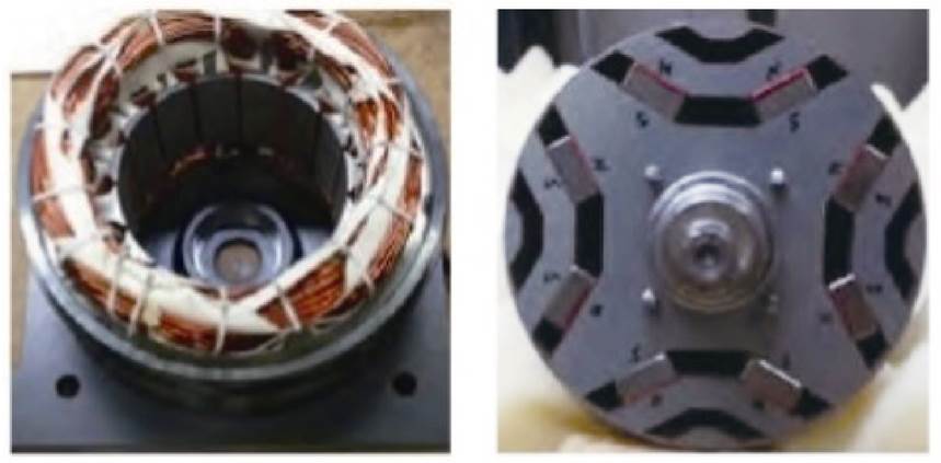
永磁辅助同步磁阻电机研究现状及发展趋势
曹恒佩1 艾萌萌1,2 王延波1
(1. 哈尔滨理工大学电气与电子工程学院 哈尔滨 150080 2. 哈尔滨理工大学大型电机电气与传热技术国家地方联合工程研究中心 哈尔滨 150080)
摘要 永磁辅助同步磁阻电机(PMaSynRM)以其高功率密度、高效率、高性价比及宽调速范围的优点,近年来已成为行业的研究热点,特别是在家用电器、电动汽车及工业电机等领域。在国内外研究现状的基础上,该文详细介绍了永磁辅助同步磁阻电机的优化设计、转矩提升、转矩脉动抑制、机械强度、温升分布计算以及容错设计等方面的最新研究进展。分析了辅助槽与气隙等设计对转矩特性的提升;总结了中心肋与磁障等设计对机械强度的优化;解释了PMaSynRM在不同工况下的温升分布并总结了多相、绕组等设计对永磁辅助同步磁阻电机容错能力的提高。最后,考虑电机行业的发展趋势,对永磁辅助同步磁阻电机的研究发展进行展望。
关键词:永磁辅助同步磁阻电机 转矩特性 机械强度 温度分布 容错设计
0 引言
永磁辅助同步磁阻电机(Permanent Magnet assisted Synchronous Reluctance Motor, PMaSynRM)最初由意大利学者A. Vagati首次提出[1]。PMaSynRM结合了同步磁阻电机(Synchronous Reluctance Motor, SynRM)和内置式永磁同步电机(Interior Permanent Magnet Synchronous Motor, IPMSM)的特点,该电机充分利用磁阻转矩和永磁转矩,具有功率密度高、效率高、调速范围宽及体积小、质量轻等显著优点[2-6]。因工艺水平和材料的限制,当时对PMaSynRM的研究和应用并未获得足够重视。近年来,由于稀土永磁体使用量大,价格不断提升,为减轻永磁电机对稀土的依赖,减少稀土开采对环境的破坏,并在保证电机高性能的同时降低电机成本,PMaSynRM这一少稀土乃至无稀土的高效电机再次被提出,并在电动汽车和空调、洗衣机等家电领域被广泛应用[7-9]。
PMaSynRM由同步磁阻电机发展而来,通过在磁障中添加永磁材料来提供直轴永磁磁通,既能增大其交、直轴来提升磁阻转矩,又因转子磁障中添加永磁材料产生永磁转矩,增大电机的转矩密度,从而有效克服了同步磁阻电机本身低功率因数和低转矩密度的缺点。这一改变使得原有同步磁阻电机设计方法也不再完全适用于PMaSynRM,尤其需要重新对其磁障形状、尺寸、层数以及永磁体的材料、尺寸和用量进行优化设计,以使电机获得更佳的电磁性能。另外,添加永磁体后,PMaSynRM运行时的转子受力情况、损耗分布以及温度变化也将随之改变,需要对其转子机械强度和电机温升进行深入研究,以确保电机长期可靠运行。
相比于IPMSM,PMaSynRM可在保证电磁性能的同时减少永磁体用量,极大地提高了电机的性价比。尽管PMaSynRM有诸多优点,但其转矩脉动较高、损耗较大、机械强度较低的劣势也不容忽视。高转矩脉动使电机稳定性降低,影响电机甚至系统的可靠性;相比同等条件下的永磁同步电机,其效率更低;较低的机械强度会使电机高速运行时转子发生形变,从而引发事故。非多相PMaSynRM本身不具有容错性,限制了其在更广阔领域内的应用。
综上所述,PMaSynRM在设计、分析等方面存在许多常规电机所不具有的关键问题,因此不能照搬常规电机的相关设计及分析方法,而需要进行深入的研究。目前,PMaSynRM的优化设计、转矩提升、转矩脉动抑制、机械强度、温升分布预测以及容错设计及控制等方面逐渐成为国内外学者的研究热点。基于此,本文归纳总结了上述方面国内外的最新研究进展,并对其发展趋势与前景进行展望。
1 PMaSynRM与其他类型电机的对比
本文对国内外PMaSynRM的发展现状进行不完全统计,见表1。可以看出,PMaSynRM的最高转速已达60 000r/min,采用U型磁障转子结构。
表1 永磁辅助同步磁阻电机的发展
Tab.1 Development of PMaSynRM
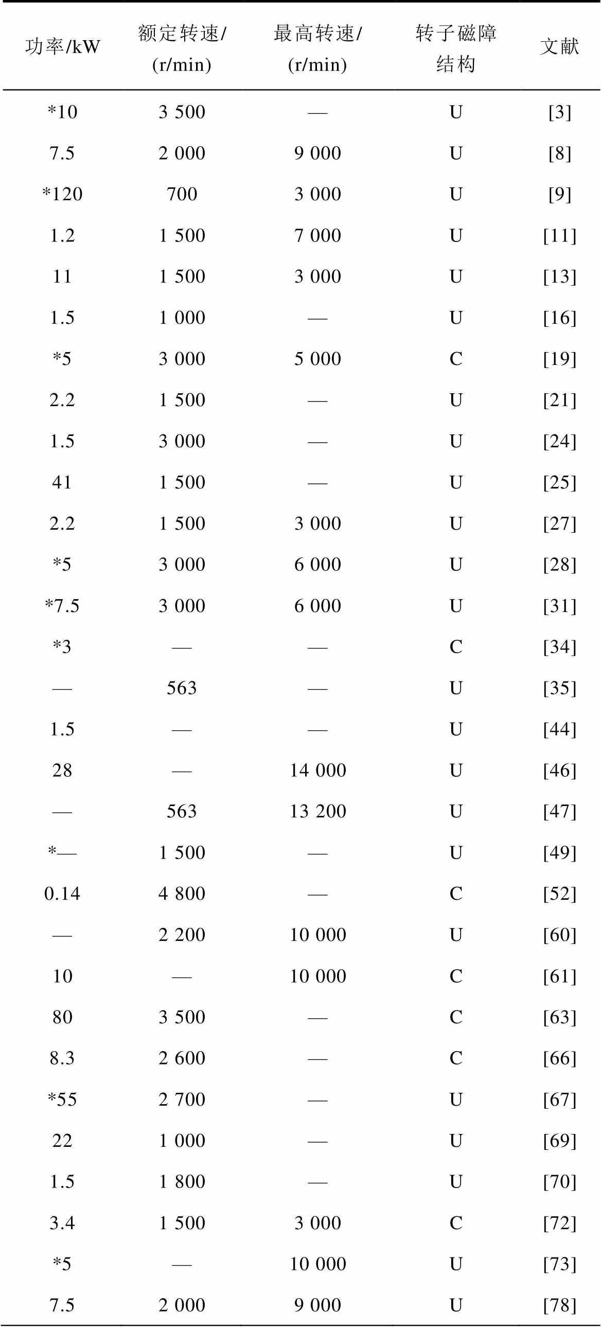
功率/kW额定转速/ (r/min)最高转速/ (r/min)转子磁障结构文献 *103 500—U[3] 7.52 0009 000U[8] *1207003 000U[9] 1.21 5007 000U[11] 111 5003 000U[13] 1.51 000—U[16] *53 0005 000C[19] 2.21 500—U[21] 1.53 000—U[24] 411 500—U[25] 2.21 5003 000U[27] *53 0006 000U[28] *7.53 0006 000U[31] *3——C[34] —563—U[35] 1.5——U[44] 28—14 000U[46] —56313 200U[47] *—1 500—U[49] 0.144 800—C[52] —2 20010 000U[60] 10—10 000C[61] 803 500—C[63] 8.32 600—C[66] *552 700—U[67] 221 000—U[69] 1.51 800—U[70] 3.41 5003 000C[72] *5—10 000U[73] 7.52 0009 000U[78]
(续)
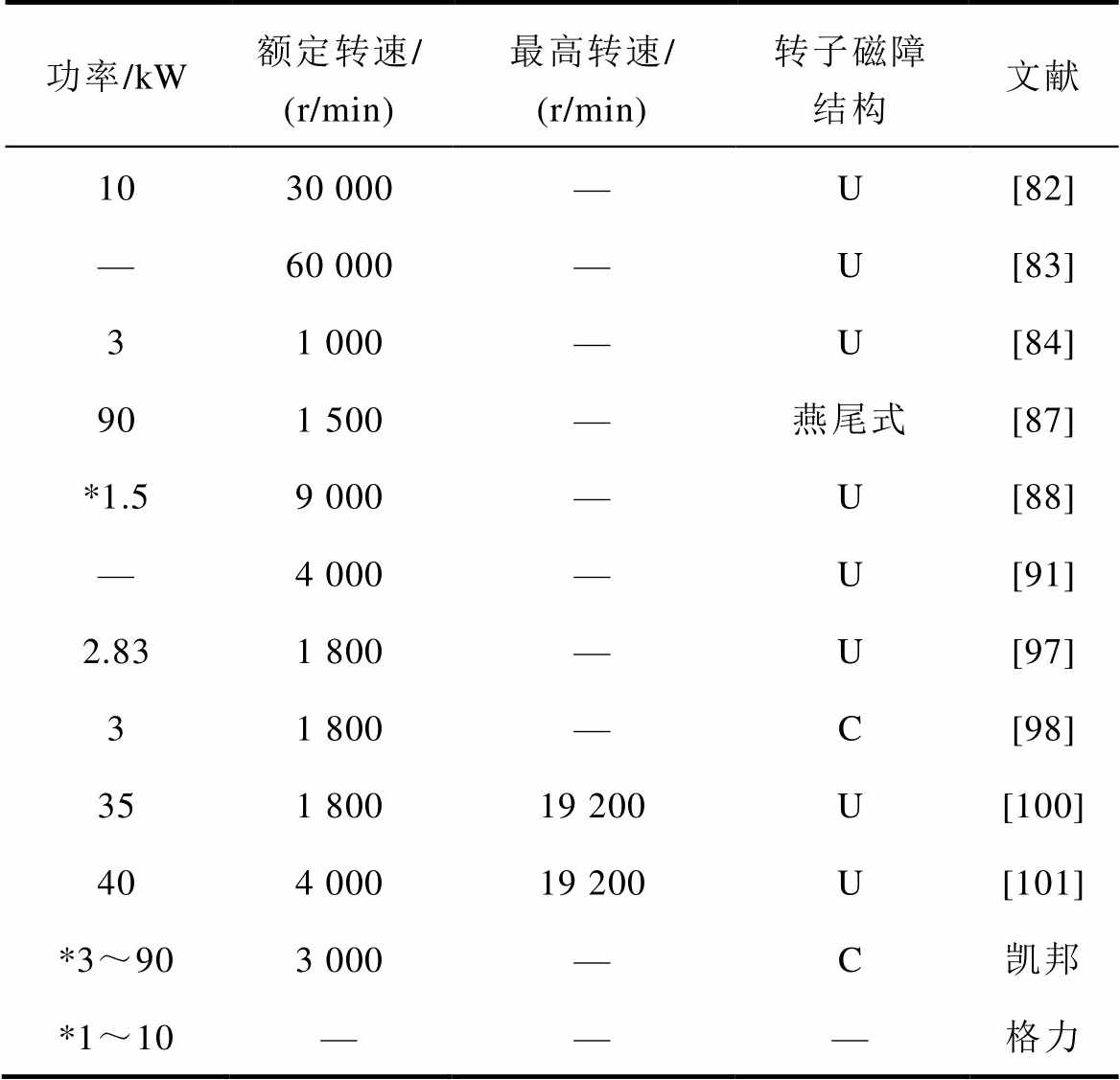
功率/kW额定转速/ (r/min)最高转速/ (r/min)转子磁障结构文献 1030 000—U[82] —60 000—U[83] 31 000—U[84] 901 500—燕尾式[87] *1.59 000—U[88] —4 000—U[91] 2.831 800—U[97] 31 800—C[98] 351 80019 200U[100] 404 00019 200U[101] *3~903 000—C凯邦 *1~10———格力
注:*表示国内永磁辅助同步磁阻电机的发展状况。
PMaSynRM通过在SynRM的转子中添加永磁体,使永磁体磁场与定子磁场相互作用产生永磁转矩,相比于SynRM,PMaSynRM在相同电流下产生的电磁转矩更大[10]。PMaSynRM吸取了IPMSM和SynRM的优点,具有高功率密度、高效率和宽调速范围等优点。
文献[11-15]对比分析了PMaSynRM与SynRM的电磁性能与优缺点。文献[16]在前者基础上应用铁氧体材料建立了IPMSM、SynRM和PMaSynRM三种电机的统一的数学模型,详细地对比分析了三种电机主要应用铁氧体时的性能。表2给出了三种电机的主要数据。
表2 三种电机设计参数
Tab.2 Three kinds of motor design parameters
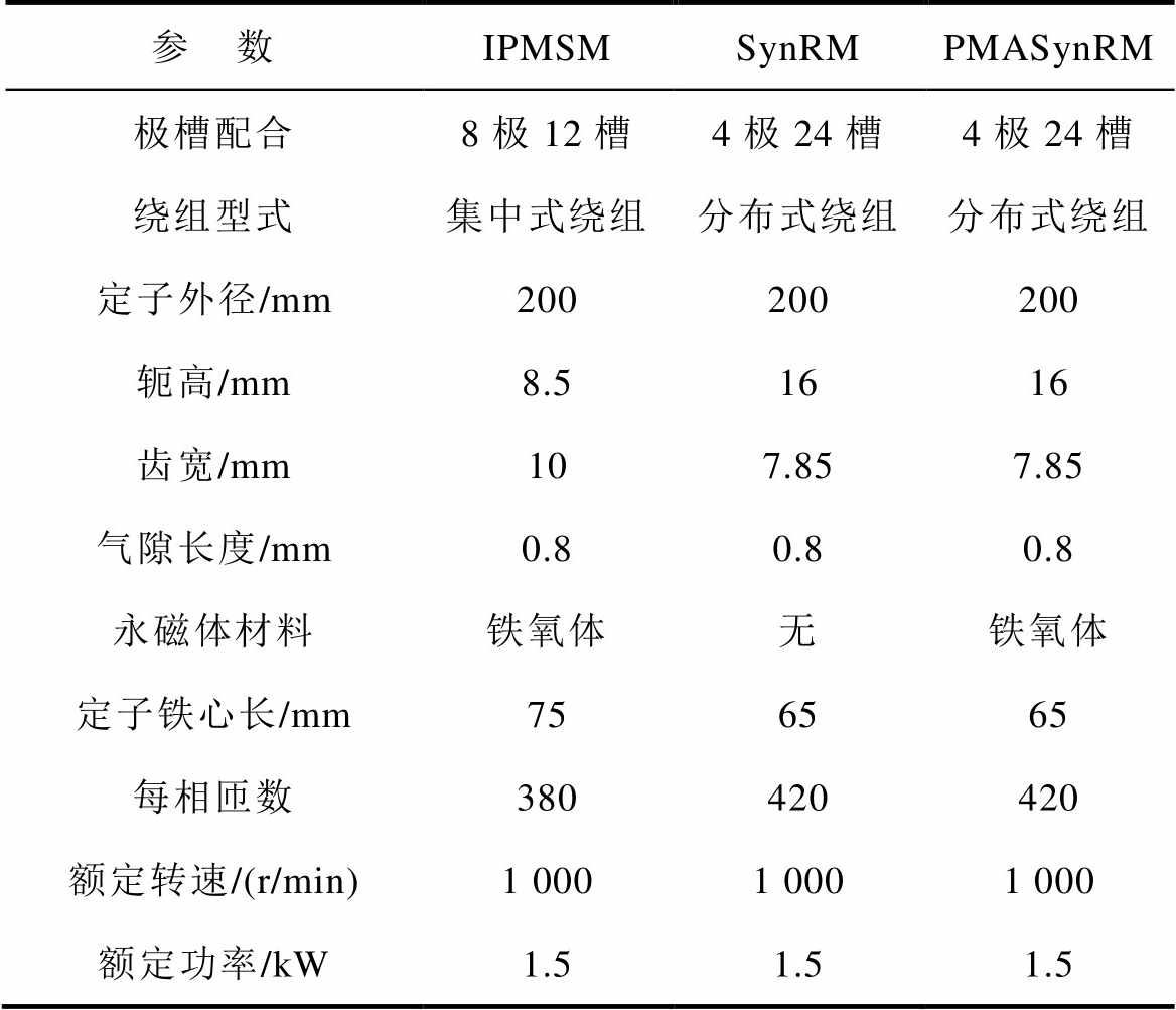
参 数IPMSMSynRMPMASynRM 极槽配合8极12槽4极24槽4极24槽 绕组型式集中式绕组分布式绕组分布式绕组 定子外径/mm200200200 轭高/mm8.51616 齿宽/mm107.857.85 气隙长度/mm0.80.80.8 永磁体材料铁氧体无铁氧体 定子铁心长/mm756565 每相匝数380420420 额定转速/(r/min)1 0001 0001 000 额定功率/kW1.51.51.5
图1为三种电机绕组联结形式、磁力线分布和磁通密度分布。对于IPMSM,d轴置于磁化方向,q轴置于d轴后90°电角度。对于SynRM,d轴置于无磁障方向,q轴置于d轴后90°电角度。PMaSynRM的d、q轴方向与SynRM相同。图2为三种电机的电流与电压的相量。由图2可知,通过在SynRM中添加永磁体形成的PMaSynRM会增大原有的凸极比,进而增大电压与电流的相位差,提高功率因数。图中, 为定子电流,Id、Iq分别为
 的直、交轴分量,Ld、Lq分别为直、交轴电感分量,q 为
 和d轴的夹角,j 为定子电压
 与
与 的夹角,w 为电角速度。
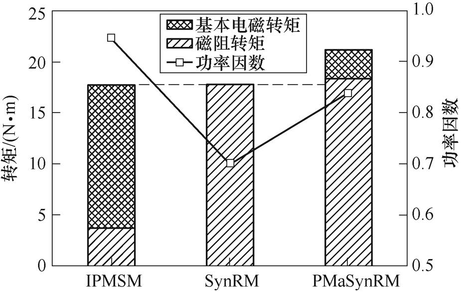
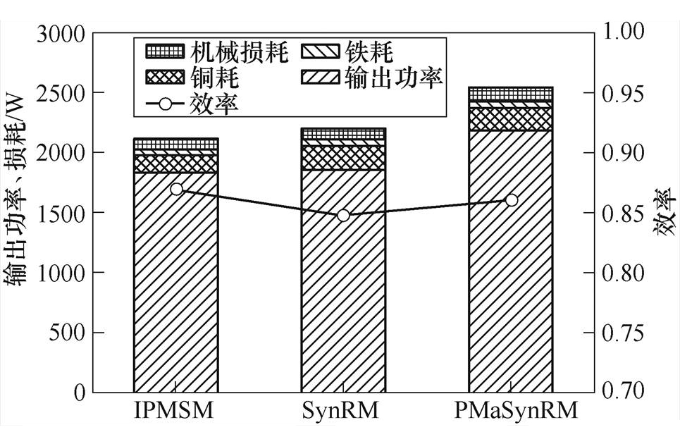
三种电机额定工作点的转矩性能和功率因数如图3所示。可见,尽管IPMSM转子具有被认为有较高的转矩特性的V型永磁体,但SynRM的额定转矩与其相同。而PMaSynRM因永磁转矩和磁阻转矩的叠加使得额定转矩最大。就功率因数而言,PMaSynRM高于SynRM,但略低于IPMSM。图4为三种电机额定工作点的输出功率、损耗和效率。电机转速相同时,输出功率与输出转矩成正比;损耗主要由铁耗、机械损耗和定子铜耗组成,文中未考虑杂耗。三种电机的机械损耗和铁耗基本相同,但PMaSynRM铜耗大于SynRM和IPMSM,IPMSM的铜耗最小,而SynRM和PMaSynRM因采用分布式绕组结构,线圈端部长,铜耗也较大,且基本相同;SynRM和IPMSM的输出功率相同,明显小于PMaSynRM;PMSM的效率略高于PMaSynRM,SynRM的效率最低。这也证明了PMaSynRM的优点。
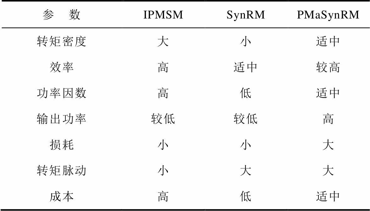
文献[17-23]给出了IPMSM、SynRM和PMaSynRM等电机的性能对比,见表3,同时表明,PMaSynRM应用铁氧体永磁体时的成本远低于应用钕铁硼的IPMSM,且PMaSynRM在较低的成本中具有较优的电磁性能。
表3 IPMSM、SynRM和PMaSynRM性能对比
Tab.3 Performance comparison of IPMSM, SynRM and PMaSynRM
参 数IPMSMSynRMPMaSynRM 转矩密度大小适中 效率高适中较高 功率因数高低适中 输出功率较低较低高 损耗小小大 转矩脉动小大大 成本高低适中
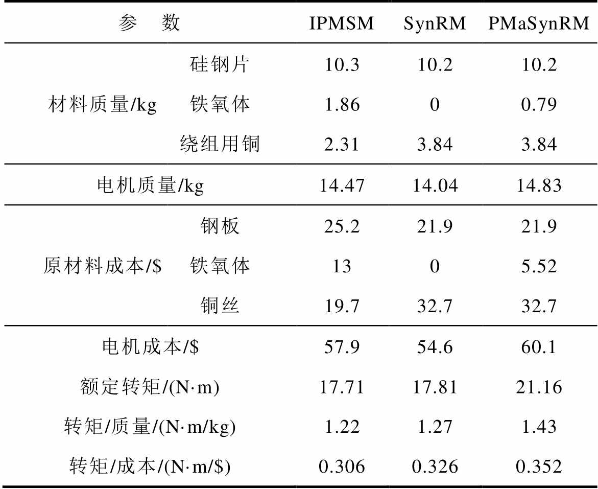
在电磁性能分析的基础上,进一步对比了同为铁氧体时的三种电机质量、有效材料成本和转矩密度,并参考了文献[24-27]中各类电机的成本、体积及经济性能,见表4。
表4 电机质量和材料成本
Tab.4 Motor weight and material cost
参 数IPMSMSynRMPMaSynRM 材料质量/kg硅钢片10.310.210.2 铁氧体1.8600.79 绕组用铜2.313.843.84 电机质量/kg14.4714.0414.83 原材料成本/$钢板25.221.921.9 铁氧体1305.52 铜丝19.732.732.7 电机成本/$57.954.660.1 额定转矩/(N·m)17.7117.8121.16 转矩/质量/(N·m/kg)1.221.271.43 转矩/成本/(N·m/$)0.3060.3260.352
由表4可见,在永磁材料均为铁氧体时,SynRM与IPMSM的额定转矩大致相同,SynRM的电机质量和成本更低。PMaSynRM应用成本更低的铁氧体材料时,尽管成本略高于SynRM与IPMSM,但性能更好、转矩密度更高。
2 永磁辅助同步磁阻电机转矩特性
目前,对PMaSynRM的研究成果中转矩提升和转矩脉动抑制首屈一指。转矩的提升是通过合理选择永磁体放置位置、改变转子的结构和形状等措施以提高电机的永磁转矩和磁阻转矩;而转矩脉动的抑制主要是针对永磁转矩脉动、磁阻转矩脉动以及齿槽转矩脉动,通过采取相邻磁极下磁障宽度不对称设计、非均匀气隙,选择合适的磁障位置、尺寸、形状以及定子开设辅助槽等措施来实现[28]。
根据电机的运行原理,PMaSynRM电磁转矩简化公式[29]为
式中,Tem为电磁转矩;p为电机极对数; 为永磁体产生的磁链;is为定子电流空间矢量;
 为is与d轴的夹角。
式(1)第一项为永磁磁场与定子磁场相互作用产生的永磁转矩;第二项为由于电机交直轴电感差而产生的磁阻转矩,增大交直轴电感的差可有效提高PMaSynRM的转矩[30]。因此,交、直轴电感以及磁链是影响PMaSynRM转矩特性的3个重要参数。
2.1 转矩提升
文献[31-37]分别对集中绕组和分布绕组等绕组形式和分数槽、整数槽下的PMaSynRM电磁性能进行了对比分析,通过数值模拟发现,分数槽集中绕组的PMaSynRM具有更大的电磁转矩,但由于集中绕组时电机转矩脉动较大,功率因数和效率较低,因此目前应用较广泛的是分布式绕组。
2.1.1 裂比对转矩的影响
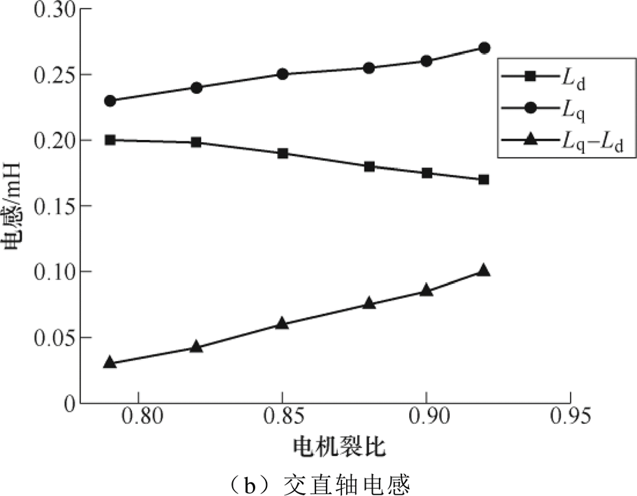
文献[38]根据解析法和有限元法分别研究了PMaSynRM裂比即定子内外径之比对电机转矩的影响,得到平均转矩和电感随裂比的变化曲线,如图5所示。其中,图5a为电机平均转矩随裂比的变化曲线,图5b为电机交直轴电感随裂比的变化曲线。研究发现,电机的交直轴电感随裂比变化进而引起转矩的变化。裂比在0.85~0.90范围内时电机性能较优。当裂比增加时,交轴磁路饱和导致其电感减小,且直轴电感也略微减少,凸极比以及电感差会变大,此时电机的输出转矩达到最大;之后随着裂比的进一步增加,电机定子冲片更加紧凑,相同条件下磁路饱和加剧,尽管电感差增大,但此时永磁转矩减小,二者共同作用使得转矩减小。文献[39]研究发现,当电机极数较大时,可适当降低轭部尺寸,裂比应选择大些;而极数较小时,为避免磁路饱和以及降低铁心中的磁通密度,应使齿宽适当大些,尤其是轭部尺寸较为厚实,因此裂比适当选择小些。
2.1.2 永磁体的位置和材料对转矩的影响
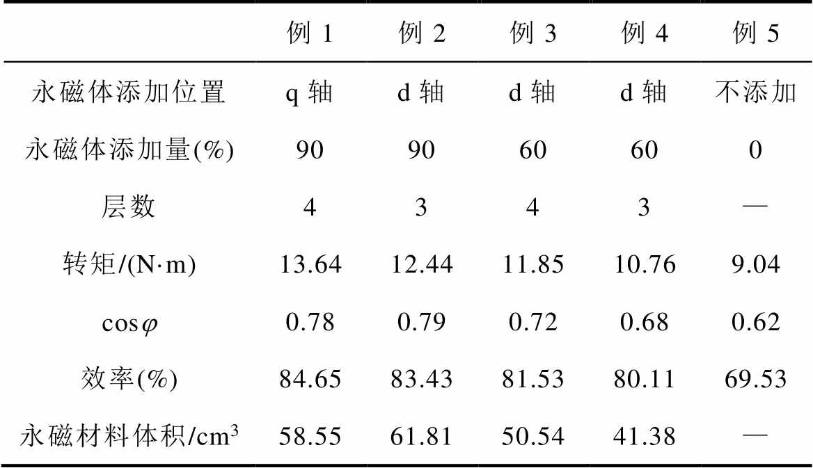
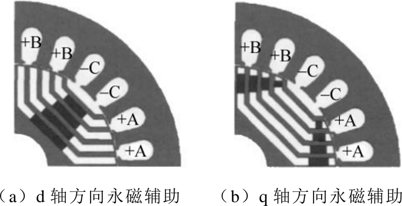
文献[40-43]为获得较大的交直轴电感差以提高电机电磁转矩,对比分析了V型、C型和U型三种转子磁障结构对PMaSynRM电磁性能的影响,表明C型磁障电机的转矩密度略大,而U型磁障的局部饱和和漏磁现象更为严重,其功率因数和效率略低。文献[44-49]比较了在U型磁障中向d、q轴正负方向添加永磁体和永磁体添加位置对电磁性能的影响,如图6所示。表5给出了在不同位置添加永磁体以及所添加永磁体占磁障总体积不同比例时的电机性能对比。从表5中可以看出,在永磁材料用量大致相同,位置在q轴时,电机效率和转矩更佳。
表5 不同永磁体添加方案下的电机性能对比
Tab.5 Comparison of motor performance under different permanent magnet adding schemes
例1例2例3例4例5 永磁体添加位置q轴d轴d轴d轴不添加 永磁体添加量(%)909060600 层数4343— 转矩/(N·m)13.6412.4411.8510.769.04 cosj0.780.790.720.680.62 效率(%)84.6583.4381.5380.1169.53 永磁材料体积/cm358.5561.8150.5441.38—
文献[50]对磁障内的永磁体的材料进行研究,将记忆电机的理念应用到了PMaSynRM上,重新对转子进行设计,采用铁氧体和铝镍钴混合永磁与多层磁障结构,有效发挥了铝镍钴高剩磁的特性,实现了电机弱磁区转矩的提高和损耗的降低。
2.1.3 转子结构对转矩的影响
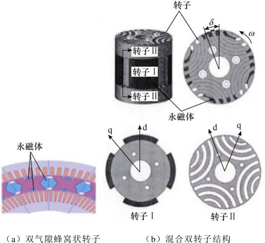
文献[51]提出一种双气隙蜂窝状转子PMaSynRM,在SynRM单气隙的基础上逐步细化转子形状,最终优化得到如图7a所示的双气隙蜂窝状转子结构,该结构具有更优的转矩特性。文献[52-54]给出了混合双转子结构,如图7b所示,转子Ⅰ为永磁转子,转子Ⅱ为磁阻转子,通过转子轴向配置角度的设计,达到最佳内功率因数角,使得永磁转矩和磁阻转矩的最大值在相同的电流相位处叠加而实现最优的转矩特性。
2.2 转矩脉动抑制
PMaSynRM运行时除了磁阻转矩与永磁转矩外,还有齿槽转矩,并产生附加的转矩脉动,尽管转矩脉动不影响平均输出转矩,却会造成振动和噪声。PMaSynRM的转矩脉动的主要原因是齿槽转矩、永磁转矩脉动和磁阻转矩脉动。
2.2.1 辅助槽对齿槽转矩的抑制
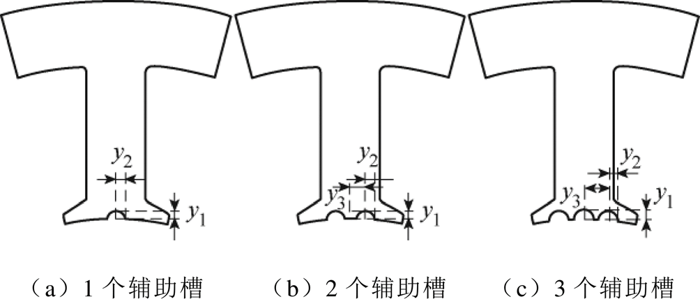
为削弱齿槽转矩引起的转矩脉动,文献[55]对比研究了4极18槽分数槽集中绕组时定子齿顶开辅助槽对转矩脉动的削弱效果,图8为齿顶开1~3个辅助槽的示意图。发现开2个辅助槽时每个槽距下等距齿槽效应周期数从2增加到6,能有效削弱齿槽效应引起的齿槽转矩,但文献[55]表明,对于4极12槽整数槽分布绕组开2个辅助槽对转矩脉动的影响较小,且有可能恶化转矩脉动,所以在不同极槽配合下需要选择不同个数的辅助槽来降低齿槽转矩对转矩脉动造成的影响。其中,y1为辅助槽的高度,y2为辅助槽的半径,y3为两个辅助槽之间的距离。
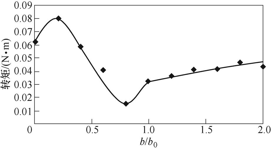
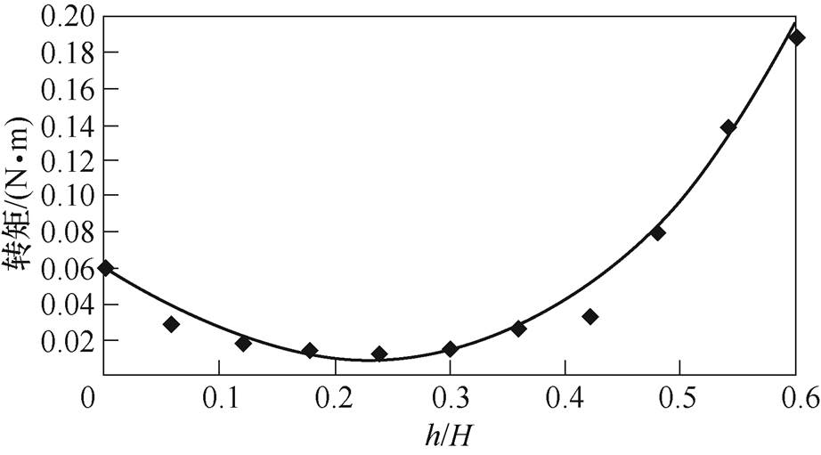
文献[56-58]进一步研究了辅助槽的尺寸对转矩脉动的影响,图9、图10分别为齿槽转矩幅值随辅助槽槽宽及槽深的变化曲线,图中,b为实际槽宽,b0为假定槽宽,h为槽深,H为槽肩到槽口距离。
由图9、图10可知,适当的辅助槽尺寸可有效抑制PMaSynRM转矩脉动,但所开辅助槽过大或过小反而会增加齿槽转矩,研究表明,实际槽宽b在0.5b0~0.8b0范围内,槽深h在0.2H附近时辅助槽效果最优。
2.2.2 磁障结构对转矩脉动的抑制
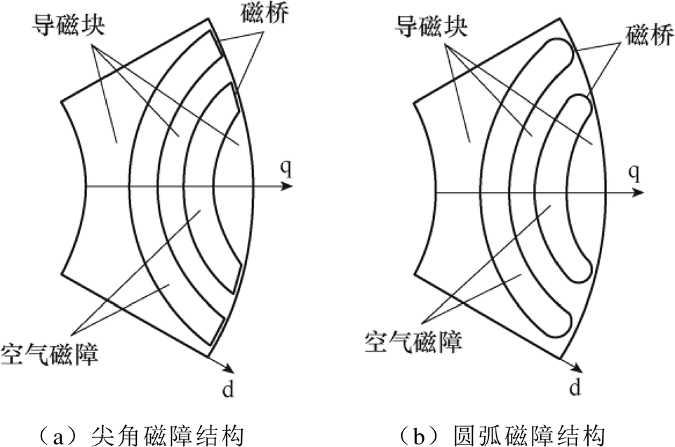
针对PMaSynRM转矩脉动抑制,现有成果多聚焦于对磁障的研究,发现其形状、尺寸和位置等参数对转矩特性有较大的影响。文献[59]对比分析了转子磁障末端是尖角和圆弧两种结构时的转矩特性,图11给出两种磁障端部结构。研究发现,尖角型磁障结构能减小q轴漏磁,对磁障层数较多的转子,端部采用尖角时转矩脉动更小;而磁障层数较少时则是圆弧磁桥转矩脉动更小。
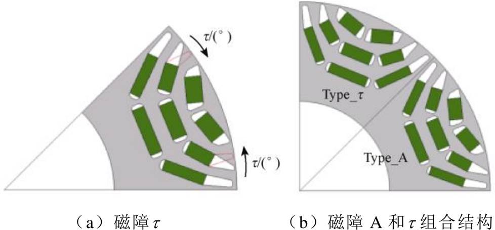
文献[60-63]进一步将磁障端部尖角改为锥形,之后向极中心线旋转每极所对磁障两端的中间隔磁桥。转子磁障端部向极中心线旋转如图12所示。图12a的“t ”型结构是将图12b中A型结构中的第
二层磁障张角改变,进而改变瞬时转矩相位,实现谐波转矩的相互抵消,从而降低转矩脉动。
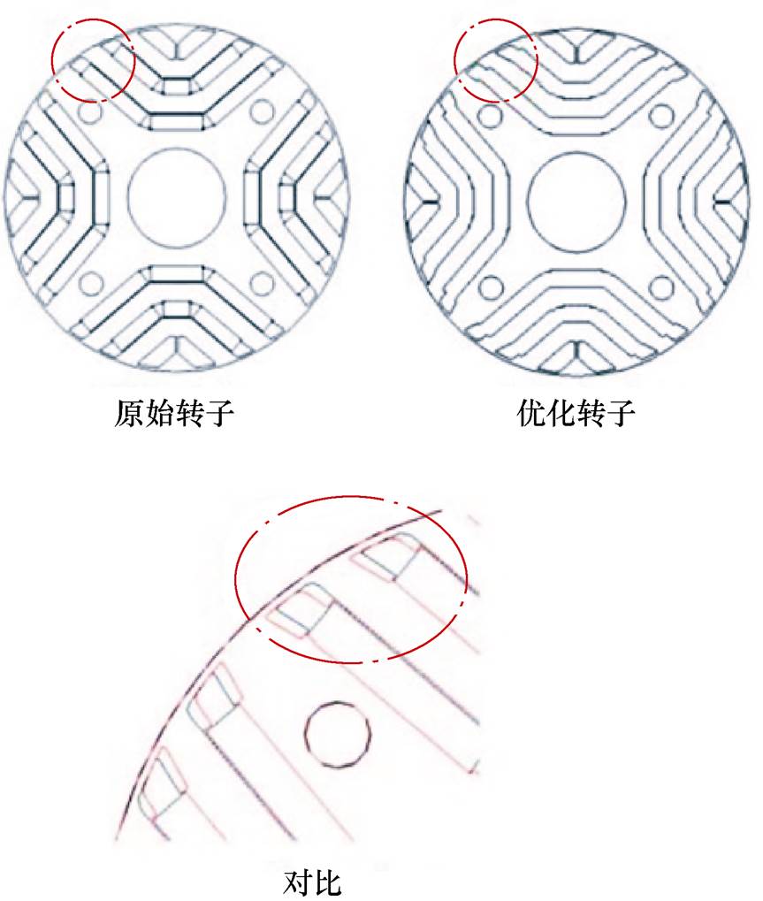
文献[64-65]是对每极所对尖角型磁障两端中间的隔磁桥分别背离极中心线偏移,如图13所示,通过错位的磁障尖端减小转矩脉动。
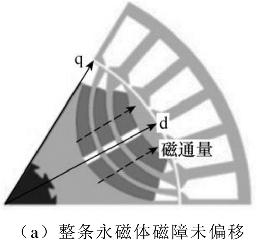
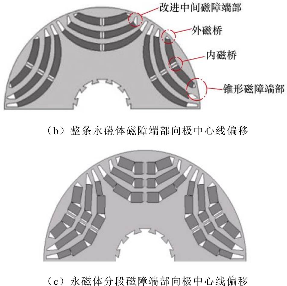
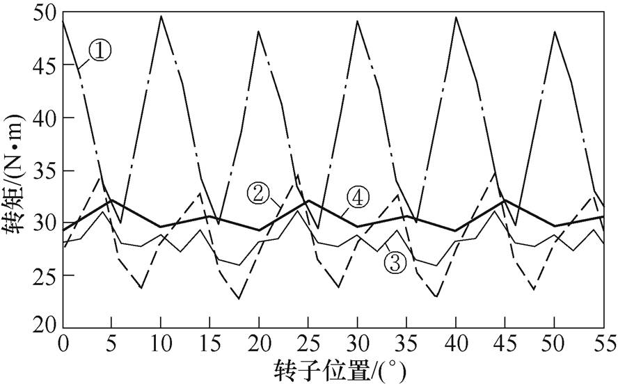
文献[66]对比分析了三种转子结构下的PMaSynRM转矩脉动情况,图14给出转子几何结构。图14a为磁障未偏移,整条永磁体仅有与磁障适型的结构,图14b为磁障端部向极中心线偏移,整条永磁体与磁障适型的结构,图14c为磁障端部向极中心线偏移,永磁体分段且与磁障适型的结构。
图15为这三种转子结构的PMaSynRM和轮辐式永磁同步电机的脉动转矩对比。图中,①轮辐式永磁同步电机;②整条永磁体且具有磁障未偏移的PmaSYnRM;③整条永磁体且除磁障端部向极中心线偏移的PmaSynRM;④永磁体分段且除磁障端部向极中心线偏移的PmaSynRM。由图15可知,磁障端部向极中心线偏移有效削弱了转矩脉动,永磁体分段后,最大转矩略有增加,转矩脉动也进一步被削弱,图14c的转子结构的转矩脉动最小。
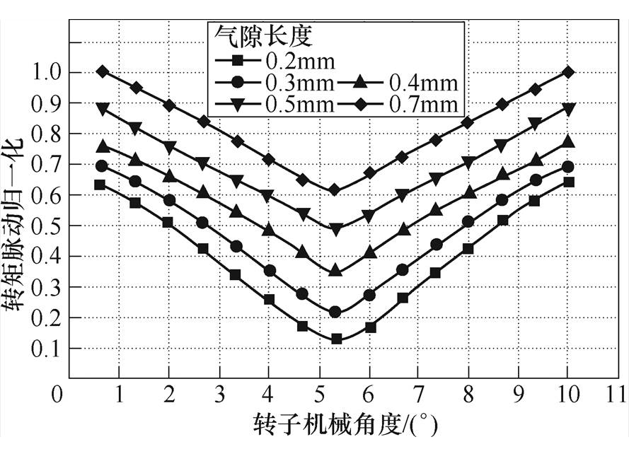
文献[67-68]研究了气隙对PMaSynRM电磁性能的影响,图16为不同转子机械角度下单边气隙长
对PMaSynRM转矩脉动的影响曲线族。设转矩脉动归一化为转矩最大值与平均值的差和转矩最大值的比。由图可知,转子机械角度不变时,转矩脉动随单边气隙长的减小而减小,不同气隙长时转矩脉动的最小值均出现在转子机械角度为5.4°时;单边气隙长一定时,转矩脉动随转子机械角度的变化趋势呈现先减少后增大,转子机械角度为5.4°时转矩脉动最小。由此可见,在保证装配工艺及运行可靠的条件下,PMaSynRM应尽可能选择较小的气隙来削弱转矩脉动。
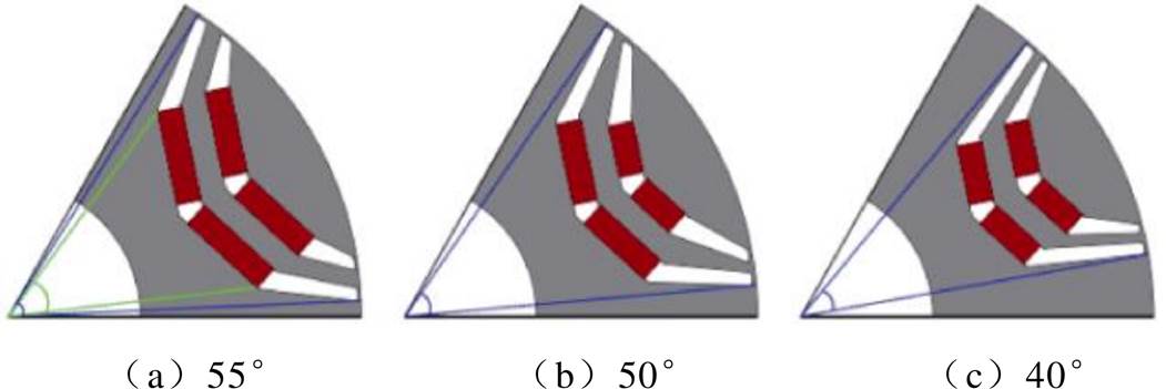
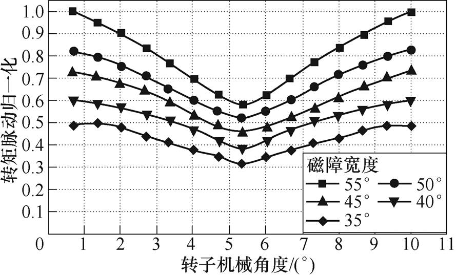
文献[69]进一步研究了每极磁障宽度(即转子每极磁障对应转子冲片圆心的圆心角)对转矩脉动的影响,图17为不同的磁障宽度示意图,图18为磁障宽度对PMaSynRM转矩脉动的影响曲线。可知,转矩脉动随着每极磁障宽度的减小而减小;而在不同磁障宽度下,转矩脉动随转子机械角度先减小后增大,当前转子机械角度为5.4°时,转矩脉动达到最小。
文献[70]探讨了相邻两极之间的磁障距离对PMaSynRM转矩脉动的影响,发现随着极间磁障距离的减小,转矩脉动先减小后增加,所以选择合适的磁障位置可以实现相对更小的转矩脉动。
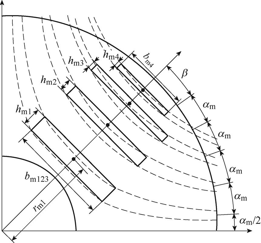
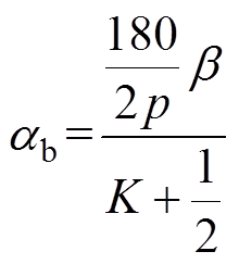
文献[71-73]提出当虚拟张角b、磁障间夹角ab以及磁障层数K满足式(2)时,转矩脉动的抑制效果最好。而b 的变化也影响磁障与轴线距离的变化,会对转矩脉动产生一定的影响[74]。如图19所示为转子磁障设计参数。图中,hm1~hm4依次为第一~四层磁障宽度,第一~三层磁障长度相同为bm123,第四层磁障长度为bm4,转子半径为rm1。
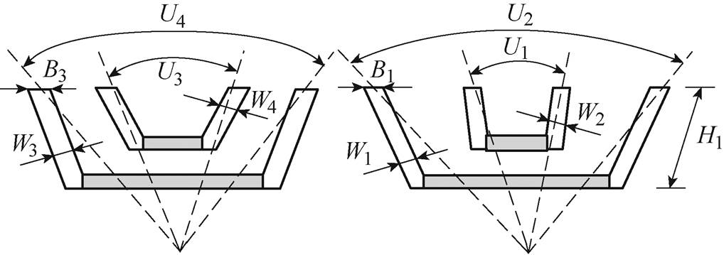
除此之外,对转子进行不对称设计,也可达到削弱转矩脉动的效果。转子不对称方法有多种,文献[75]重新设计每层磁障张角,非对称转子磁障如图20所示,得到两种不同磁障张角的转子冲片,其主要谐波幅值相等而相位相差180°。将两种磁障结构交替使用,叠加后以实现削弱转矩脉动的效果。图中,U1、U3为第一层磁障开角角度,U2、U4为第二层磁障开角角度,W2、W4为第一层磁障宽度,W1、W3为第二层磁障宽度,B1、B3为第二层磁障末端宽度,H1为磁障的长度。
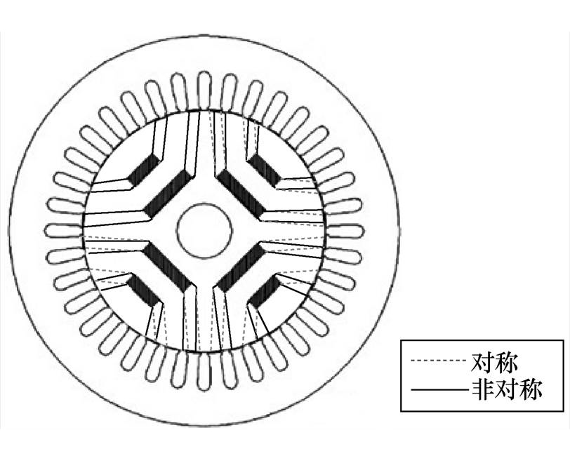
文献[76]采用完全不对称转子结构来抑制电机转矩脉动,其特点是转子每极永磁体槽所跨角度均不相同。文献[77]以某一极为基准,将每极下磁障端部位置逐一偏离某一特定角度,如图21所示,达到转子不对称效果,同时也避免了定转子槽对齐时的齿槽效应,从而抑制转矩脉动。
3 强度、温升及容错研究
目前,对PMaSynRM的研究除上述电磁设计、转矩特性外,研究人员还对其转子机械强度、温度预测以及容错性能等方面进行了探讨。
3.1 转子机械强度
PMaSynRM运行中受离心力、单边磁拉力等力作用,可能使转子薄弱位置尤其是隔磁桥处发生形变,甚至断裂引发事故[78-79]。如何在保证电磁性能的同时提高其转子机械强度也是PMaSynRM的研究热点之一。
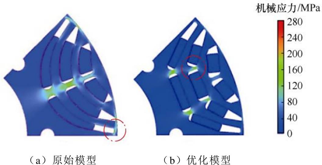
文献[80-83]针对图22所示的两种转子结构进行了应力分析,从图中可以发现,在中心肋和外磁桥处所受应力较大,通过增加中心肋(即内磁桥)数量,并就形状进行适当优化,可使最大应力点由外磁桥分散到多个磁桥上,能有效降低外磁桥的机械应力,提升转子强度。
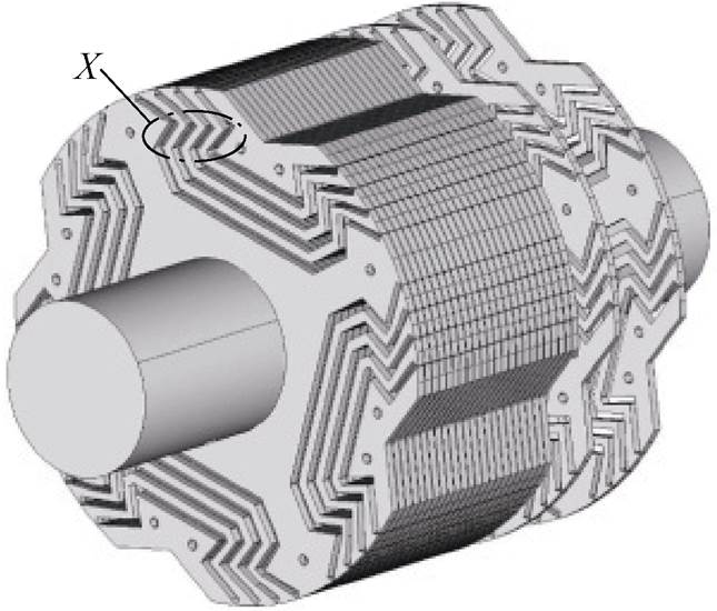
另外,将磁障边界调整为圆形,可适当降低机械应力[84],亦或改变磁障夹角的半径或形状来提高机械强度[85-86],也有研究将磁障设计为燕尾式,并通过增加等效磁障厚度来提高其机械强度,燕尾型磁障如图23所示[87]。
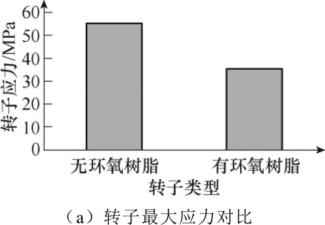
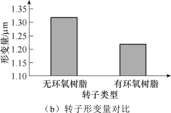
文献[88]比较了转子磁障中有无环氧树脂填充物时转子应力的变化,磁障中环氧树脂填对转子应力结的影响如图24所示,实验表明,在转子磁障中添加环氧树脂填充物后,提高了电机永磁体与硅钢片的整体性,也增强了电机转子的机械强度。
3.2 温度预测
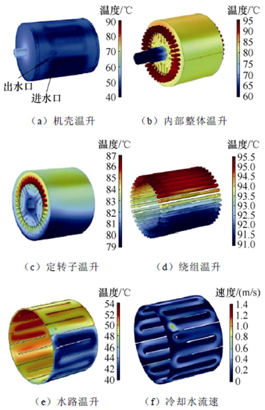
运行时的温度和温升分布对电机性能有显著影响,因此,发热和冷却一直是电机的重点研究领域。与其他电机相比,PMaSynRM的热分析文献相对较少,主要集中于冷却水道、电机稳态温升分布以及多物理场耦合分析等方面。文献[89]对一台轴向折返式水冷结构的PMaSynRM采用流固耦合方法计算得到电机最大损耗时的温升分布,以确保定子绕组和永磁体的最高温度都在允许范围内。图25所示为应用轴向折返式水冷结构的最大损耗下的PMaSynRM流固耦合温升计算。
图25中机壳温升较小,电机内部整体温升较大,在电机内部绕组的温升最高,永磁体温升次之,图25f为轴向折返式水冷结构。由图25e可知,电机的进出口温差大致为8℃,证明水冷系统能够带走一定的热量来达到电机散热的要求。
文献[90]对PMaSynRM样机进行了磁-热耦合研究,对其单边气隙长、永磁体体积等参数进行优化,获取电机在稳态温升时具有最佳的电磁性能。样机优化前后温度对比见表6,由表6可知,优化后绕组和铁氧体的温度大幅下降,同时铁氧体的剩磁也有所提升,可使电机在正常运行中具有较低的温升和更好的性能,保证了电机的可靠性。
表6 样机优化前后温度对比
Tab.6 Temperature comparison of prototype before and after optimization
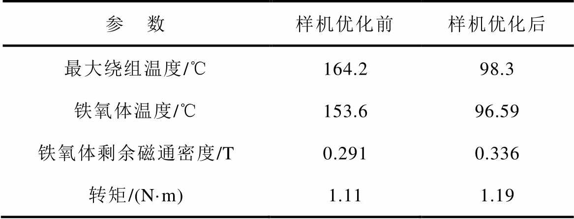
参 数样机优化前样机优化后 最大绕组温度/℃164.298.3 铁氧体温度/℃153.696.59 铁氧体剩余磁通密度/T0.2910.336 转矩/(N·m)1.111.19
文献[91-92]建立了九相PMaSynRM的三维瞬态热模型和集总参数热模型预测电机在故障条件下的不对称温度分布,为PMaSynRM在容错设计中建立电磁热耦合模型提供了参考。
3.3 容错设计
PMaSynRM多是三相电机,发生缺相故障时,容错性能较差。近年来,有学者将PMaSynRM和容错电机相结合,用于提升PMaSynRM的容错性能,使其在故障时能持续运行。PMaSynRM的容错设计大致可分为三类:一是在电驱动系统增加裕度,利用资源的重复配置达到容错能力的提升,如并联多个电机,容错运行时切除故障电机即可[93];二是将PMaSynRM设计成多相电机;三是综合前两类进行模块化设计,使整个系统兼具独立驱动和多自由度的特点。
文献[94-95]设计了一台五相PMaSynRM,样机定转子结构如图26所示,并对其在不同开路故障下的转矩特性进行了分析计算,提出适当的电流控制策略,保证故障后的电机安全运行,实现平稳的电机转矩。通过在每个健康相电流引入一个适当的角位移达到减小故障后转矩谐波的目的。文献[96-97]对五相PMaSynRM在不同运行状态下的温升进行了研究,指出电机在容错控制时也应考虑热效应的影响,并进一步采用对称分量分析方法提取故障条件的特征,判断故障类型。通过由正序、负序、零序的峰值相比得到的两个信号比指标,总结出不同故障状态下的信号比指标的变化规律,达到初步确认故障类型,再通过故障后相位的变化规律,最终确认故障类型。文献[98]为提高PMaSynRM在容错状态下的电磁性能,采用动态超前电流相位的容错控制方法,以获得更大的转矩。当发生故障时,转矩脉动会发生严重畸变,所以文献[99]以转矩误差为目标,建立模型预测控制系统,以过去的状态作为输入,生成对未来状态的预测,达到预测故障的作用。
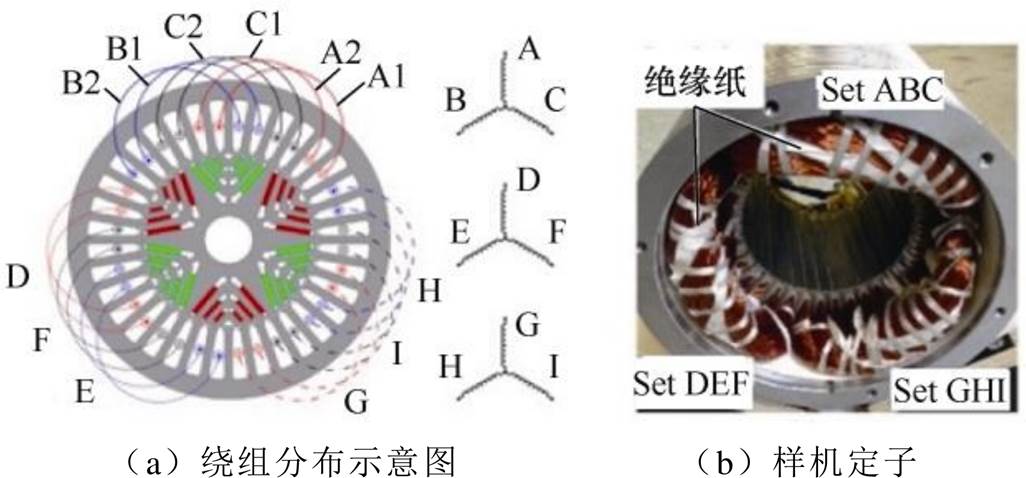
为确保电机在某相发生故障时健康相仍正常工作,需尽可能减少故障相对健康相的影响。文献[100-102]对绕组进行模块化设计,采用三倍冗余九相PMaSynRM,通过改变绕组得联结型式,得到空间上相对独立的三套三相绕组,从而实现每套绕组之间有一定的物理隔离、磁隔离、电隔离和热隔离。
图27所示为三倍冗余九相PMaSynRM绕组分布示意图,每套绕组由标准三相逆变器驱动,当电机某相发生故障时,直接切断故障相电流,此时另外两套独立的三相绕组使电机仍能在故障状态时保持一定的电磁性能。文献[103-104]使用电磁热耦合模拟仿真对不同故障条件下故障区域温度变化进行了对比,预测出最坏情况下故障检测和缓解的最大允许时间,为故障运行时采取相应措施提供了参考时间。
4 结论
近年来,PMaSynRM发展迅速,国内外对其研究取得了丰硕的成果,产业化势头良好。但国内与国外相比仍有较大的差距,对PmaSynRM的研制多集中在小功率和低转速。综合国内外研究现状看,尽管目前在电动汽车、家用电器等领域有了较广泛的应用,但PMaSynRM仍存在亟需深入研究的关键技术问题,主要包括:
1)损耗与温升。随着PMaSynRM新的应用场合不断出现,对其最大功率需求日趋增加,使得电机电磁负荷和功率密度不断提高,加之转子磁障结构对其运行磁场的影响,尤其是高速应用环境,PMaSynRM损耗的准确计算仍值得深入研究。在此基础上,研究不同工况、不同冷却条件、不同转子结构对电机温升分布规律的影响和多物理场双向耦合方法预测电机全域温升也是该类电机电磁设计、结构优化甚至扩大应用范围必须解决的关键问题之一。
2)高转速化、高功率密度化或高转矩密度化。对PMaSynRM进行更合理的结构设计和电磁设计,充分利用永磁转矩和磁阻转矩,实现更高的功率密度或转矩密度,达到更好的电磁性能。充分发挥PMaSynRM高功率密度、高效率等优势向高速领域发展,以期在航空航天领域发挥更大作用。
3)多目标优化设计。PMaSynRM的优化设计涉及到电磁、流体流动及传热、应力场、转子动力学以及容错控制等方面的多约束条件下的多目标综合优化设计。目前,PMaSynRM的优化设计多为单一性能如电磁性能的优化,多目标协同优化正逐渐成为其优化设计的主要方向,借助多物理场双向耦合分析,实现电机的损耗控制、转矩脉动抑制、转子强度、冷却结构及全域温升预测及抑制等多目标系统优化。
4)容错电机与故障诊断。对PMaSynRM进行更合理的容错设计,并研究其容错控制策略。合理设计PMaSynRM的转子结构、绕组型式及连接方式、永磁体设置位置及形状等,进一步提升其抗短路能力和电磁性能,准确诊断系统的故障类型、故障位置等也是今后研究的重点。
参考文献
[1] Vagati A, Pastorelli M, Francheschini G, et al. Design of low-torque-ripple synchronous reluctance motors[J]. IEEE Transactions on Industry Applications, 1998, 34(4): 758-765.
[2] 狄冲, 鲍晓华, 潘晋, 等. 基于Elmer开源有限元平台的铁氧体辅助同步磁阻电机的建模和分析[J]. 电工技术学报, 2022, 37(5): 1136-1144.
Di Chong, Bao Xiaohua, Pan Jin, et al. Modelling and analysis of a ferrite assisted synchronous reluctance machine based on the open-source platform Elmer[J]. Transactions of China Electrotechnical Society, 2022, 37(5): 1136-1144.
[3] 李岱岩. 新型非对称转子永磁辅助式同步磁阻电机研究[D]. 沈阳: 沈阳工业大学, 2019.
[4] 张清枝, 牛联波, 艾永乐. 永磁辅助磁阻同步电机性能分析[J]. 电力系统保护与控制, 2011, 39(22): 129-132.
Zhang Qingzhi, Niu Lianbo, Ai Yongle. Performance analysis of permanent magnet assisted reluctance synchronous machine[J]. Power System Protection and Control, 2011, 39(22): 129-132.
[5] 王瑾, 李岩, 贾建国, 等. 反电动势和凸极率对高效永磁同步磁阻电机稳态特性影响分析[J]. 电工技术学报, 2020, 35(22): 4688-4698.
Wang Jin, Li Yan, Jia Jianguo, et al. Analysis of the influence of back-EMF and saliency ratio on steady- state characteristics of a high efficiency permanent magnet synchronous reluctance motor[J]. Transa- ctions of China Electrotechnical Society, 2020, 35(22): 4688-4698.
[6] 李新华, 汪思敏, 易梦云, 等. 钕铁硼永磁磁阻同步电机及其仿真分析[J]. 微特电机, 2018, 46(8): 49-51.
Li Xinhua, Wang Simin, Yi Mengyun, et al. Simu- lation analysis of NdFeB permanent magnet relu- ctance synchronous motor[J]. Small & Special Electrical Machines, 2018, 46(8): 49-51.
[7] 柴凤, 史妍雯, 刘越. 永磁同步磁阻电动机综述[J]. 微特电机, 2015, 43(10): 81-87.
Chai Feng, Shi Yanwen, Liu Yue. Research review of permanent magnet assisted synchronous reluctance motor[J]. Small & Special Electrical Machines, 2015, 43(10): 81-87.
[8] Nicorici A M, Oprea C, Martis C. Performance evaluation of a 7.5kW permanent magnet assisted synchronous reluctance machine for light electric vehicles[C]//IEEE 2018 International Conference and Exposition on Electrical and Power Engineering (EPE), Iasi, Romania, 2018: 129-132.
[9] 李新华, 阮波, 徐竟成, 等. 电动大巴永磁辅助磁阻同步电动机仿真分析[J]. 微特电机, 2014, 42(3): 1-3.
Li Xinhua, Ruan Bo, Xu Jingcheng, et al. Simulation analysis of PMaSynRM used in electrical bus[J]. Small & Special Electrical Machines, 2014, 42(3): 1-3.
[10] 黄辉, 胡余生. 永磁辅助同步磁阻电机设计与应用[M]. 北京: 机械工业出版社, 2017.
[11] Nattuthurai S, Neelamegham R. Design and perfor- mance evaluation of SynRM and ferrite assisted- SynRM for EV application using FEA[C]//IEEE 2017 International Conference on Smart Technologies for Smart Nation (SmartTechCon), Bengaluru, India, 2017: 492-497.
[12] Aghazadeh H, Afjei E, Siadatan A. Comparative analysis of permanent magnet assisted synchronous reluctance motor with external-rotor[C]//IEEE 2019 10th International Power Electronics, Drive Systems and Technologies Conference (PEDSTC), Shiraz, Iran, 2019: 22-27.
[13] Neusüs S, Binder A. Experimental comparison of synchronous reluctance motors with and without ferrite magnet assistance[C]//IEEE 2019 IEEE International Electric Machines & Drives Conference, San Diego, CA, USA, 2019: 1464-1471.
[14] Bottesi O, Alberti L. Comparison of small-size generator for high-efficiency hydroelectric energy production[C]//2017 IEEE International Electric Machines and Drives Conference, Miami, FL, USA, 2017: 1-8.
[15] 黄辉, 胡余生, 陈东锁, 等. 变频压缩机用无稀土永磁辅助同步磁阻电机的研究[J]. 微电机, 2014, 47(4): 9-12.
Huang Hui, Hu Yusheng, Chen Dongsuo, et al. Research of rare-earthless permanent-magnet-assisted synchronous reluctance motor for variable speed compressor[J]. Micromotors, 2014, 47(4): 9-12.
[16] Shen Jianxin, Cai Shun, Shao Hang, et al. Evaluation of low-cost high-performance synchronous motors for ventilation application[C]//IEEE 2015 International Conference on Sustainable Mobility Applications, Renewables and Technology (SMART), Kuwait, 2015: 1-6.
[17] 喻琦, 王心坚, 章桐. 永磁同步电机与同步磁阻电机能量转换特性对比[J]. 机电一体化, 2017, 23(11): 27-33.
Yu Qi, Wang Xinjian, Zhang Tong. Comparison of energy conversion characteristics between permanent magnet synchronous motor and synchronous relu- ctance motor[J]. Mechatronics, 2017, 23(11): 27-33.
[18] 丁娟, 朱江源, 常久鹏, 等. 纯电动车中永磁同步电机的研究[J]. 汽车电器, 2016(1): 13-16.
Ding Juan, Zhu Jiangyuan, Chang Jiupeng, et al. Research on PMSM for pure EV[J]. Auto Electric Parts, 2016(1): 13-16.
[19] 蔡顺. 同步磁阻电机性能分析与结构优化[D]. 杭州: 浙江大学, 2017.
[20] 沈建新, 蔡顺, 郝鹤, 等. 同步磁阻电机分析与设计(连载之十) 同步磁阻电机与开关磁阻电机定转子的组合应用[J]. 微电机, 2017, 50(2): 71-76.
Shen Jianxin, Cai Shun, Hao He, et al. Analysis and design of synchronous reluctance machines part Ⅹ: combination of stators and rotors of synchronous reluctance machine and switched reluctance machine[J]. Micromotors, 2017, 50(2): 71-76.
[21] Jia Shaofeng, Zhang Ping, Liang Deliang, et al. Design and comparison of three different types of IE4 efficiency machines[C]//IEEE 2019 22nd Inter- national Conference on Electrical Machines and Systems (ICEMS), Harbin, China, 2019: 1-4.
[22] Kobayashi M, Morimoto S, Sanada M, et al. Perfor- mance comparison between PMASynRM with Dyfree bonded magnets and IPMSM with sintered magnets for automotive applications under various temperature conditions[C]//IEEE 2019 21st European Conference on Power Electronics and Applications (EPE '19 ECCE Europe), Genova, Italy, 2019: 1-9.
[23] 沈建新, 蔡顺, 袁赛赛. 同步磁阻电机分析与设计(连载之一)概述[J]. 微电机, 2016, 49(10): 72-79, 83.
Shen Jianxin, Cai Shun, Yuan Saisai. Analysis and design of synchronous reluctance machines part Ⅰ: an overview[J]. Micromotors, 2016, 49(10): 72-79, 83.
[24] Prakht V, Dmitrievskii V, Kazakbaev V. Theoretical performance analysis of ultra premium efficiency PM assisted synchronous reluctance motor with ferrite magnets[C]//IEEE 2018 International Conference on Industrial Engineering, Applications and Manu- facturing (ICIEAM), Moscow, Russia, 2018: 1-6.
[25] Cai Haiwei, Guan Bo, Xu Longya. Low-cost ferrite PM-assisted synchronous reluctance machine for electric vehicles[J]. IEEE Transactions on Industrial Electronics, 2014, 61(10): 5741-5748.
[26] Prakht V, Dmitrievskii V, Kazakbaev V. Mathema- tical modeling ultra premium efficiency (IE5 class) PM assisted synchronous reluctance motor with ferrite magnets[C]//IEEE 2018 25th International Workshop on Electric Drives: Optimization in Control of Electric Drives (IWED), Moscow, Russia, 2018: 1-6.
[27] Zimmermann M, Schupp L, Piepenbreier B. Operating strategy and iron loss model of a permanent magnet assisted synchronous reluctance machine with a ribless rotor[C]//IEEE 2018 21st International Conference on Electrical Machines and Systems (ICEMS), Jeju, 2018: 338-343.
[28] 沈建新, 蔡顺, 郝鹤, 等. 同步磁阻电机分析与设计(连载之十二)永磁辅助同步磁阻电机的设计研究[J]. 微电机, 2017, 50(3): 79-84, 88.
Shen Jianxin, Cai Shun, Hao He, et al. Analysis and design of synchronous reluctance machines part Ⅻ: investigation of permanent magnet assisted syn- chronous reluctance machines[J]. Micromotors, 2017, 50(3): 79-84, 88.
[29] 魏超, 孙德强, 任延生, 等. 基于Maxwell 2D的永磁辅助同步磁阻电机的参数化建模及分析[J]. 电机与控制应用, 2019, 46(12): 55-60.
Wei Chao, Sun Deqiang, Ren Yansheng, et al. Para- metric modeling and analysis of permanent magnet assisted synchronous reluctance motor on Maxwell 2D software[J]. Electric Machines & Control Appli- cation, 2019, 46(12): 55-60.
[30] 张景峰, 倪瑞林, 申春艳, 等. 磁阻转矩对永磁电机性能的影响分析[J]. 电子世界, 2016(22): 157- 158.
Zhang Jingfeng, Ni Ruilin, Shen Chunyan, et al. Analysis of the effect of permanent magnet resistance on the performance of permanent magnet motor[J]. Electronics World, 2016(22): 157-158.
[31] 年恒震. 电动汽车分数槽永磁同步磁阻电机设计[D]. 沈阳: 沈阳工业大学, 2019.
[32] 沈建新, 蔡顺, 郝鹤, 等. 同步磁阻电机分析与设计(连载之四)绕组形式的分析与选择[J]. 微电机, 2016, 49(11): 93-97.
Shen Jianxin, Cai Shun, Hao He, et al. Analysis and design of synchronous reluctance machines part Ⅳ: analysis and utility of winding configurations[J]. Micromotors, 2016, 49(11): 93-97.
[33] 沈建新, 蔡顺, 郝鹤, 等. 同步磁阻电机分析与设计(连载之六)转子均匀分布磁障的参数优化[J]. 微电机, 2016, 49(12): 84-88.
Shen Jianxin, Cai Shun, Hao He, et al. Analysis and design of synchronous reluctance machines part Ⅵ: parameter optimization of evenly distributed rotor barriers[J]. Micromotors, 2016, 49(12): 84-88.
[34] 肖勇, 黄辉, 胡余生, 等. 绕组形式对永磁辅助同步磁阻电机影响研究[J]. 日用电器, 2017(7): 66-68.
Xiao Yong, Huang Hui, Hu Yusheng, et al. Research on the influence of windings on permanent-magnet- assisted synchronous reluctance motor[J]. Electrical Appliances, 2017(7): 66-68.
[35] Tap A, Xheladini L, İmeryüz M, et al. Effects of the stator design parameters on the torque performance of a PMaSynRM[C]//IEEE 2017 11th IEEE International Conference on Compatibility, Power Electronics and Power Engineering, Cadiz, Spain, 2017: 346-351.
[36] Huang Hui, Hu Yusheng, Xiao Yong, et al. Research of parameters and antidemagnetization of rare-earth- less permanent magnet-assisted synchronous relu- ctance motor[J]. IEEE Transactions on Magnetics, 2015, 51(11): 1-4.
[37] Bianchi N, Bolognani S, Frare P. Design criteria for high-efficiency SPM synchronous motors[J]. IEEE Transactions on Energy Conversion, 2006, 21(2): 396-404.
[38] 胡慧莹. 永磁同步磁阻电机参数化设计方法及转矩优化研究[D]. 哈尔滨: 哈尔滨工业大学, 2018.
[39] 沈建新, 蔡顺, 郝鹤, 等. 同步磁阻电机分析与设计(连载之三)极对数与裂比的优化设计[J]. 微电机, 2016, 49(11): 90-92, 97.
Shen Jianxin, Cai Shun, Hao He, et al. Analysis and design of synchronous reluctance machines part Ⅲ: optimization of number of pole-pairs and split ratio[J]. Micromotors, 2016, 49(11): 90-92, 97.
[40] 王风华. 车用永磁同步电机拓扑结构比较研究[J]. 电气传动, 2019, 49(6): 93-96.
Wang Fenghua. Comparative research on topology of vehicle permanent magnet synchronous motor[J]. Electric Drive, 2019, 49(6): 93-96.
[41] 李威扬, 黄鹏程, 孟曙光, 等. 永磁同步电机转子磁钢拓扑结构与运行工况匹配性分析[J]. 防爆电机, 2018, 53(2): 19-22.
Li Weiyang, Huang Pengcheng, Meng Shuguang, et al. Matching analysis of rotor magnet steel topology structure with operation condition of permanent- magnet synchronous motor[J]. Explosion-Proof Electric Machine, 2018, 53(2): 19-22.
[42] 沈建新, 蔡顺, 郝鹤, 等. 同步磁阻电机分析与设计(连载之七)转子不均匀分布磁障的对比分析[J]. 微电机, 2017, 50(1): 83-86.
Shen Jianxin, Cai Shun, Hao He, et al. Analysis and design of synchronous reluctance machines part Ⅶ: comparative analysis of unevenly distributed rotor barriers[J]. Micromotors, 2017, 50(1): 83-86.
[43] 董新伟, 王一飞, 杨磊. 车用高性能永磁同步电机磁极设计综述[J]. 微电机, 2019, 52(11): 97-100.
Dong Xinwei, Wang Yifei, Yang Lei. A survey of magnetic pole design for high performance permanent magnet synchronous motors[J]. Micromotors, 2019, 52(11): 97-100.
[44] 李新华, 黄启振, 刘天知. 正负凸极永磁辅助式磁阻同步电动机研究[J]. 微特电机, 2015, 43(7): 1-3, 9.
Li Xinhua, Huang Qizhen, Liu Tianzhi. Research on permanent magnet assisted synchronous reluctance motor with the positive and negative salient pole[J]. Small & Special Electrical Machines, 2015, 43(7): 1-3, 9.
[45] Zhao Wenliang, Chen Dezhi, Lipo T A, et al. Perfor- mance improvement of ferrite-assisted synchronous reluctance machines using asymmetrical rotor configurations[J]. IEEE Transactions on Magnetics, 2015, 51(11): 1-4.
[46] Hu Yaohua, Liu Chuang, Zhu Shushu, et al. Opti- mized design of rotor structure in ferrite-assisted synchronous reluctance machines for electric vehicle application[C]//IEEE 2016 Eleventh International Conference on Ecological Vehicles and Renewable Energies (EVER), Monte Carlo, Monaco, 2016: 1-7.
[47] Tap A, Xheladini L, Asan T, et al. Effects of the rotor design parameters on the torque production of a PMaSynRM for washing machine applications[C]// IEEE 2017 International Conference on Optimization of Electrical and Electronic Equipment (OPTIM) & 2017 Intl Aegean Conference on Electrical Machines and Power Electronics (ACEMP), Brasov, Romania, 2017: 370-375.
[48] Tap A, Xheladini L, Yilmaz M, et al. Comprehensive design and analysis of a PMaSynRM for washing machine applications[J]. IET Electric Power Appli- cations, 2018, 12(9): 1311-1319.
[49] 梅柏杉, 张翔建, 冯江波, 等. U型多磁障式永磁辅助同步磁阻电机转子分析与设计[J]. 微特电机, 2017, 45(5): 11-14.
Mei Baishan, Zhang Xiangjian, Feng Jiangbo, et al. Analysis and design on PM assist synchronous reluctance motor with U-shaped barriers rotor[J]. Small & Special Electrical Machines, 2017, 45(5): 11-14.
[50] 杨晨, 白保东, 陈德志, 等. 可变磁通永磁辅助同步磁阻电机设计与性能分析[J]. 电工技术学报, 2019, 34(3): 489-496.
Yang Chen, Bai Baodong, Chen Dezhi, et al. Design and analysis of a variable flux permanent magnet assisted synchronous motor[J]. Transactions of China Electrotechnical Society, 2019, 34(3): 489-496.
[51] Morimoto S, Asano Y, Kosaka T, et al. Recent technical trends in PMSM[C]//IEEE 2014 Inter- national Power Electronics Conference (IPEC- Hiroshima 2014-ECCE ASIA), Hiroshima, Japan, 2014: 1997- 2003.
[52] 申海振. 新型混合转子永磁同步磁阻电机设计与分析[D]. 济南: 山东大学, 2019.
[53] 杜锦华, 薛运田. 新型永磁磁阻电机的结构和电磁参数关系分析[J]. 中国科技论文, 2016, 11(23): 2640-2644.
Du Jinhua, Xue Yuntian. Analysis of the relationship between the structure and the electromagnetic para- meters for permanent magnetic reluctance machines[J]. China Sciencepaper, 2016, 11(23): 2640-2644.
[54] Zhang Yue, Yu Siyang, Liu Guangwei, et al. Com- parative research for a novel dual-stator synchronous machine with permanent magnet-reluctance com- posite rotor[J]. IEEE Transactions on Applied Superconductivity, 2020, 30(4): 1-5.
[55] 沈建新, 蔡顺, 郝鹤, 等. 同步磁阻电机分析与设计(连载之五)定子铁心的优化设计[J]. 微电机, 2016, 49(12): 80-83.
Shen Jianxin, Cai Shun, Hao He, et al. Analysis and design of synchronous reluctance machines part Ⅴ: stator core optimization[J]. Micromotors, 2016, 49(12): 80-83.
[56] 刘伟, 陈丽香, 唐任远. 定子齿顶开辅助槽削弱永磁电机齿槽转矩的方法[J]. 电气技术, 2009, 10(8): 51-53.
Liu Wei, Chen Lixiang, Tang Renyuan. Reducing the cogging torque in permanent magnet machines by introducing auxiliary slot in the top of stator teeth[J]. Electrical Engineering, 2009, 10(8): 51-53.
[57] Wang Xiuhe, Yang Yubo, Fu Dajin. Study of cogging torque in surface-mounted permanent magnet motors with energy method[J]. Journal of Magnetism and Magnetic Materials, 2003, 267(1): 80-85.
[58] Zhu Z Q, Howe D. Analytical prediction of the cogging torque in radial-field permanent magnet brushless motors[J]. IEEE Transactions on Magnetics, 1992, 28(2): 1371-1374.
[59] 沈建新, 蔡顺, 郝鹤, 等. 同步磁阻电机分析与设计(连载之八)转子磁桥分析[J]. 微电机, 2017, 50(1): 87-90.
Shen Jianxin, Cai Shun, Hao He, et al. Analysis and design of synchronous reluctance machines part Ⅷ: analysis of rotor flux bridge ribs[J]. Micromotors, 2017, 50(1): 87-90.
[60] Obata M, Morimoto S, Sanada M, et al. Performance evaluation of high power and low torque ripple structure of rare-earth free PMASynRM with ferrite magnet[C]//IEEE 2013 10th International Conference on Power Electronics and Drive Systems, Kitakyushu, Japan, 2013: 714-719.
[61] Morimoto S, Ooi S, Inoue Y, et al. Experimental evaluation of a rare-earth-free PMASynRM with ferrite magnets for automotive applications[J]. IEEE Transactions on Industrial Electronics, 2014, 61(10): 5749-5756.
[62] Sanada M, Morimoto S, Inoue Y. Development of high-power PMASynRM using ferrite magnets for reducing rare-earth material use[C]//IEEE 2014 Inter- national Power Electronics Conference (IPEC- Hiroshima 2014-ECCE ASIA), Hiroshima, Japan, 2014: 3519-3524.
[63] Chai Feng, Hu Huiying, Geng Lina. Theoretical analysis of torque performance in permanent magnet- assisted synchronous reluctance motor[C]//IEEE 2017 20th International Conference on Electrical Machines and Systems (ICEMS), Sydney, NSW, Australia, 2017: 1-6.
[64] Liu Wanzhen, Liu Guangqiang, Yao Li, et al. Rotor design optimization of permanent magnet-assisted synchronous reluctance motor with ferrite magnets[C]// IEEE 2016 19th International Conference on Electrical Machines and Systems (ICEMS), Chiba, Japan, 2016: 1-5.
[65] 刘万振, 刘广强, 林岩, 等. 铁氧体辅助同步磁阻电机转子优化设计[J]. 微电机, 2017, 50(2): 17-20.
Liu Wanzhen, Liu Guangqiang, Lin Yan, et al. Rotor optimization design of ferrite magnet-assisted syn- chronous reluctance motor[J]. Micromotors, 2017, 50(2): 17-20.
[66] Montalvo-Ortiz E E, Foster S N, Cintron-Rivera J G, et al. Comparison between a spoke-type PMSM and a PMASynRM using ferrite magnets[C]//IEEE 2013 International Electric Machines & Drives Conference, Chicago, IL, USA, 2013: 1080-1087.
[67] 梁杰尚. 永磁辅助型同步磁阻电机电磁性能分析[D]. 沈阳: 沈阳工业大学, 2019.
[68] 郭伟, 赵争鸣. 新型同步磁阻永磁电机的结构与电磁参数关系分析[J]. 中国电机工程学报, 2005, 25(11): 124-128.
Guo Wei, Zhao Zhengming. Analysis of the relation between the electro-magnetic parameters and the structure of synchronous reluctance permanent mag- netic motors[J]. Proceedings of the CSEE, 2005, 25(11): 124-128.
[69] 方磊. 新能源车用永磁辅助式同步磁阻电机设计与控制方法研究[D]. 徐州: 中国矿业大学, 2018.
[70] Niazi P, Toliyat H A, Cheong D H, et al. A low-cost and efficient permanent-magnet-assisted synchronous reluctance motor drive[J]. IEEE Transactions on Industry Applications, 2007, 43(2): 542-550.
[71] 董砚, 颜冬, 荆锴, 等. 磁障渐变同步磁阻电机低转矩脉动转子优化设计[J]. 电工技术学报, 2017, 32(19): 21-31.
Dong Yan, Yan Dong, Jing Kai, et al. Rotor optimal design of the gradient flux-barrier for torque ripple reduction in synchronous reluctance motor[J]. Transa- ctions of China Electrotechnical Society, 2017, 32(19): 21-31.
[72] Zimmermann M, Piepenbreier B. Design of a per- manent magnet assisted synchronous reluctance machine enhanced for saliency based sensorless control[C]//IEEE 2017 IEEE International Electric Machines and Drives Conference, Miami, FL, USA, 2017: 1-7.
[73] 杨晨. 永磁辅助同步磁阻电机设计及转矩脉动抑制研究[D]. 沈阳: 沈阳工业大学, 2019.
[74] Ibrahim M N, Sergeant P, Rashad E M. Influence of rotor flux-barrier geometry on torque and torque ripple of permanent-magnet-assisted synchronous reluctance motors[C]//IEEE 2016 XXII International Conference on Electrical Machines (ICEM), Lausanne, Switzerland, 2016: 398-404.
[75] Piña A J, Cai Haiwei, Alsmadi Y, et al. Analytical model for the minimization of torque ripple in permanent magnets assisted synchronous reluctance motors through asymmetric rotor poles[C]//IEEE 2015 IEEE Energy Conversion Congress and Expo- sition, Montreal, QC, Canada, 2015: 5609-5615.
[76] 任武. 永磁同步伺服电动机转矩脉动抑制方法研究[D]. 武汉: 华中科技大学, 2016.
[77] Sanada M, Hiramoto K, Morimoto S, et al. Torque ripple improvement for synchronous reluctance motor using an asymmetric flux barrier arrangement[J]. IEEE Transactions on Industry Applications, 2004, 40(4): 1076-1082.
[78] Varaticeanu B D, Minciunescu P, Matei S. Design of permanent magnet assisted synchronous reluctance motor for light urban electric vehicle[C]//IEEE 2014 International Symposium on Fundamentals of Elec- trical Engineering (ISFEE), Bucharest, Romania, 2014: 1-6.
[79] 徐媚媚, 刘国海, 陈前, 等. 永磁辅助同步磁阻电机设计及其关键技术发展综述[J]. 中国电机工程学报, 2019, 39(23): 7033-7043, 7116.
Xu Meimei, Liu Guohai, Chen Qian, et al. Design and key technology development of permanent magnet assisted synchronous reluctance motor[J]. Pro- ceedings of the CSEE, 2019, 39(23): 7033-7043, 7116.
[80] Obata M, Morimoto S, Sanada M, et al. Performance of PMASynRM with ferrite magnets for EV/HEV applications considering productivity[J]. IEEE Transactions on Industry Applications, 2014, 50(4): 2427-2435.
[81] Ooi S, Morimoto S, Sanada M, et al. Performance evaluation of a high-power-density PMASynRM with ferrite magnets[C]//2011 IEEE Energy Conversion Congress and Exposition, Phoenix, AZ, 2011: 4195- 4200.
[82] Bin Tarek M T, Choi S. Center post and rib length optimization of a high speed permanent magnet assisted synchronous reluctance motor[C]//2017 IEEE International Electric Machines and Drives Con- ference, Miami, FL, USA, 2017: 1-6.
[83] Islam M Z, Arafat A, Choi S. Design of five-phase bearingless permanent magnet assisted synchronous reluctance motor for high speed applications[C]//2018 IEEE Energy Conversion Congress and Exposition. Portland, OR, USA, 2018: 4419-4424.
[84] Islam M Z, Arafat A, Bonthu S S R, et al. Design of a robust five-phase ferrite-assisted synchronous relu- ctance motor with low demagnetization and mechanical deformation[J]. IEEE Transactions on Energy Conversion, 2019, 34(2): 722-730.
[85] Jung J W, Lee B H, Kim D J, et al. Mechanical stress reduction of rotor core of interior permanent magnet synchronous motor[J]. IEEE Transactions on Mag- netics, 2012, 48(2): 911-914.
[86] Bremner R D. Bridge stresses and design in IPM machines[C]//IEEE EUROCON, StPetersburg, Russia, 2009: 655-662.
[87] Kolehmainen J. Synchronous reluctance motor with form blocked rotor[J]. IEEE Transactions on Energy Conversion, 2010, 25(2): 450-456.
[88] 娄利岗. 真空泵用永磁辅助式同步磁阻电动机设计与分析[D]. 沈阳: 沈阳工业大学, 2019.
[89] 王晓远, 杜静娟. 应用CFD流固耦合热分析车用高功率密度电机的水冷系统[J]. 电工技术学报, 2015, 30(9): 30-38.
Wang Xiaoyuan, Du Jingjuan. Design and analysis of water cooling system for HEVs high-power-density motor using CFD and thermal technology[J]. Transa- ctions of China Electrotechnical Society, 2015, 30(9): 30-38.
[90] Xheladini L, Tap A, Imeryuz M, et al. Thermal and mechanical analysis of PM assisted synchronous reluctance motor for washing machines[J]. 10th International Conference on Electrical and Electronics Engineering (ELECO), Bursa, 2017: 227-232.
[91] Shi Yanwen, Wang Jiabin, Wang Bo. Lumped- parameter and 3D thermal model of a PMASynRM under fault conditions with asymmetric temperature distribution[C]//2018 IEEE Energy Conversion Congress and Exposition, Portland, OR, USA, 2018: 6521-6528.
[92] Shi Yanwen, Wang Jiabin, Wang Bo. Transient 3-D lumped parameter and 3-D FE thermal models of a PMASynRM under fault conditions with asymmetric temperature distribution[J]. IEEE Transactions on Industrial Electronics, 2021, 68(6): 4623-4633.
[93] Ertugrul N, Soong W, Dostal G, et al. Fault tolerant motor drive system with redundancy for critical applications[C]//2002 IEEE 33rd Annual IEEE Power Electronics Specialists Conference. Proceedings (Cat. No.02CH37289), Cairns, QLD, Australia, 2002: 1457- 1462.
[94] Bonthu S S R, Arafat A, Choi S. Comparisons of rare-earth and rare-earth-free external rotor per- manent magnet assisted synchronous reluctance motors[J]. IEEE Transactions on Industrial Electro- nics, 2017, 64(12): 9729-9738.
[95] Bianchi N, Bolognani S, PrÉDai Pre M D. Impact of stator winding of a five-phase permanent-magnet motor on postfault operations[J]. IEEE Transactions on Industrial Electronics, 2008, 55(5): 1978-1987.
[96] Arafat A K M, Herbert J, Bin Tarek M T, et al. Study of the thermal effects of a five-phase permanent magnet assisted synchronous reluctance motor under fault tolerant control[C]//2017 IEEE International Electric Machines and Drives Conference, Miami, FL, USA, 2017: 1-6.
[97] Arafat A, Choi S, Baek J. Open-phase fault detection of a five-phase permanent magnet assisted syn- chronous reluctance motor based on symmetrical components theory[J]. IEEE Transactions on Indu- strial Electronics, 2017, 64(8): 6465-6474.
[98] Arafat A K M, Choi S. Fault tolerant control of five-phase permanent magnet assisted synchronous reluctance motor based on dynamic current phase advance[C]//2015 IEEE Energy Conversion Congress and Exposition, Montreal, QC, Canada, 2015: 1208- 1214.
[99] Dharmasena S, Choi S. Model predictive control of five-phase permanent magnet assisted synchronous reluctance motor[C]//2019 IEEE Applied Power Electronics Conference and Exposition, Anaheim, CA, USA, 2019: 1885-1890.
[100] Wang Bo, Wang Jiabin, Griffo A, et al. A general modeling technique for a triple redundant 3×3-phase PMA SynRM[J]. IEEE Transactions on Industrial Electronics, 2018, 65(11): 9068-9078.
[101] Wang Bo, Wang Jiabin, Griffo A, et al. A fault- tolerant machine drive based on permanent magnet- assisted synchronous reluctance machine[J]. IEEE Transactions on Industry Applications, 2018, 54(2): 1349-1359.
[102] Wang Bo, Wang Jiabin, Griffo A, et al. Experimental assessments of a triple redundant nine-phase fault- tolerant PMA SynRM drive[J]. IEEE Transactions on Industrial Electronics, 2019, 66(1): 772-783.
[103] Shi Yanwen, Wang Jiabin, Wang Bo. Electromagnetic- thermal coupled simulation under various fault con- ditions of a triple redundant 9-phase PMASynRM[J]. IEEE Transactions on Industry Applications, 2020, 56(1): 128-137.
[104] Shi Yanwen, Wang Jiabin, Wang Bo. EM-thermal coupled simulation under various fault conditions of a triple redundant 9-phase PMASynRM[C]//2018 IEEE Energy Conversion Congress and Exposition, Portland, OR, USA, 2018: 5757-5764.
Research Status and Development Trend of Permanent Magnet Assisted Synchronous Reluctance Motor
Cao Hengpei1 Ai Mengmeng1,2 Wang Yanbo1
(1. School of Electrical and Electronic Engineering Harbin University of Science and Technology Harbin 150080 China 2. The Key Lab of National and Local United Engineering for Electric & Heat Transfer Technology of Large Electrical Machine Harbin University of Science and Technology Harbin 150080 China)
Abstract Permanent magnet assisted synchronous reluctance motor (PMaSynRM) has become a research hotspot in the industry in recent years, especially in the fields of household appliances, electric vehicles and industrial motors, due to its advantages of high power density, high efficiency, high cost performance and wide speed range. Based on the research status at home and abroad, this paper introduces the latest research progress in PMaSynRM's optimization design, torque boost, torque ripple suppression, mechanical strength, temperature rise distribution calculation, and fault-tolerant design. This paper also analyzes the improvement of auxiliary slot and air gap design on torque characteristics, summarizes the optimization of mechanical strength by the design of central ribs and magnetic barriers; and explains the temperature rise distribution of PMaSynRM under different working conditions, and summarizes the effects of multi-phase and winding design on the fault tolerance of PMaSynRM. Finally, considering the development trend of the motor industry, the research and development of PMaSynRM are prospected.
keywords:Permanent magnet assisted synchronous reluctance motor (PmaSynRM), torque characteristics, mechanical strength, temperature distribution, fault-tolerant design
DOI: 10.19595/j.cnki.1000-6753.tces.210434
中图分类号:TM352
国家自然科学基金(52077047)和黑龙江省自然基金(LH2020E092)资助项目。
收稿日期 2021-04-01
改稿日期 2021-12-31
作者简介
曹恒佩 男,1997年生,硕士研究生,研究方向为永磁辅助同步磁阻电机设计。E-mail: 870152819@qq.com
艾萌萌 男,1991年生,讲师,研究方向为特种电机及电力变压器设计。E-mail: aimengmeng@hrbust.edu.cn(通信作者)
(编辑 崔文静)


 为定子电流,I
 与
与 的夹角,
的夹角,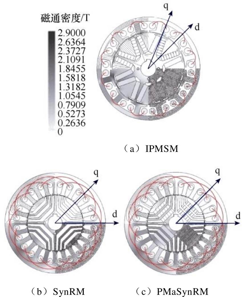



 (1)
(1)
 为永磁体产生的磁链;i
 为i
为i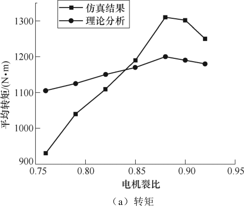

 (2)
(2)
