 (1)
(1)摘要 在电机的径向力波调制中,谐波电流注入法是行之有效的方法,实现谐波电流注入法的关键是建立谐波电流注入补偿模型及参数辨识。该文根据麦克斯韦应力张量法,首先,推导出表贴式三相永磁同步电机由电磁作用产生的极槽径向力波的时空分布模型,判断具有补偿作用的谐波电流频次;其次,推导出单频次谐波电流注入补偿模型,并采用最小二乘法和牛顿迭代法进行参数辨识;再次,推导出双频次谐波电流同时注入时产生的耦合径向力波模型,并采用最小二乘法进行参数辨识;最后,推导出多频次谐波电流注入补偿模型。通过Ansys仿真和样机实验验证模型的正确性和有效性。
关键词:表贴式永磁同步电机 谐波电流注入 径向力波 参数辨识
永磁同步电机在水下航行器驱动中应用越来越广泛,电机通过机座向航行器壳体传递结构振 动[1-2],在这些振动中,低频振动是最重要的因素[3],它不容易被减振器吸收,能通过航行器壳体传递到水中,是影响水下航行器隐蔽性的主要原因。水下航行器常用的表贴式永磁同步电机,在卧式安装时,电机的气隙磁场作用在定子上的径向电磁力波形成的振动是对外传播的主要成分。国内外对径向电磁振动的抑制多是通过对材料和结构进行优化来实现的,但是极槽引起的径向振动是无法用结构优化来消除的,这就需要用控制方法来实现对极槽振动的抑制。
目前,抑制电机振动的控制方法有滤波器[4]、电压补偿[5]、脉宽调制[6-7]、特定次谐波消除调制[8-9]、混合空间调制策略[10-11]、前馈补偿[12]、谐振控制 器[13-17]和重复控制[18]等,这些控制方法的研究目标主要是抑制电机转矩脉动引起的切向振动,而在抑制径向振动方面,相关研究[19-20]是通过减小励磁电流中的谐波成分来减小电机的径向振动,没有对极槽效应引起的径向振动实现主动抑制。且上述研究多是对电流波形的目标进行优化,没有建立起行之有效的电流与特征力的补偿模型。
本文主要对表贴式三相永磁同步电机的极槽径向力波的谐波电流补偿模型及参数辨识进行研究。首先,判断具有补偿作用的谐波电流频次;其次,推导出单频次谐波电流注入补偿模型及参数辨识;再次,推导出双频次谐波电流同时注入时产生的耦合径向力波模型及参数辨识;最后,推导出多频次谐波电流注入补偿模型。通过Ansys仿真和样机实验验证所建模型的正确性和有效性。
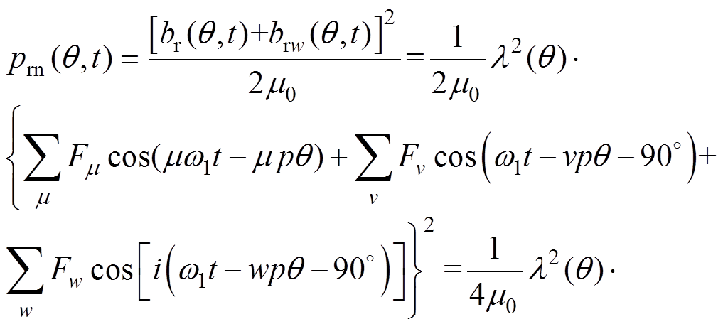
永磁同步电机的气隙磁场由永磁磁场和电枢反应磁场两部分组成。忽略磁路饱和,永磁电机的气隙磁场[21-23]可表示为
(1)式中,q 为空间机械角度; 为径向气隙磁通密度;
 和
和 分别为永磁磁动势和径向电枢磁动势;
 为只考虑定子开槽,转子表面平滑时的气隙磁导,所以气隙磁导只随空间角度变化,不随时间变化,记为
 ,可得
,可得
 (2)
(2)
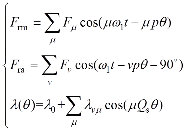
式中,m 为磁动势谐波的次数,m=2r+1(r=1, 2, 3, ×××);v为电枢反应磁场谐波次数; 为m 次径向永磁磁动势谐波幅值;
 为v次径向电枢磁动势谐波幅值;
 为谐波磁导幅值;p为极对数;Qs为定子槽数;w1为基波角频率。
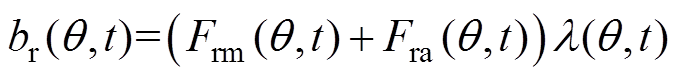
气隙中的径向电磁力是永磁电机径向力的主要来源,可用麦克斯韦应力张量法求得,有
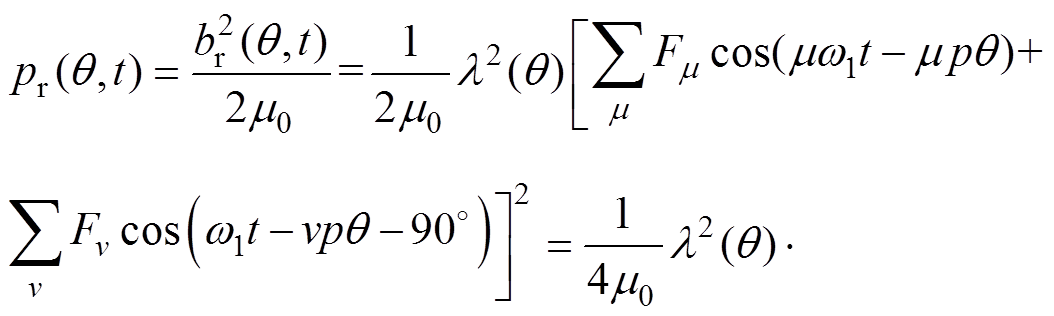
 (3)
(3)
因为 ,所以通过式(3)可知,永磁同步电机极槽径向力波频率是
 (
( )的偶数倍。
三相电流分别注入i次谐波电流,有
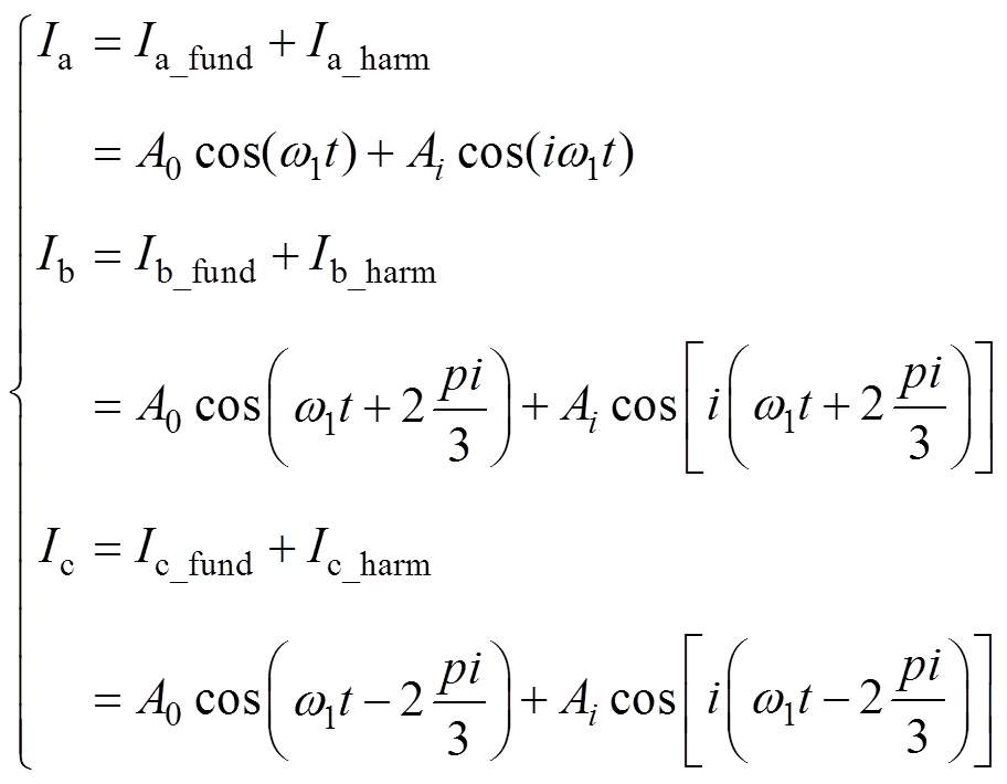 (4)
(4)式中, 为三相电流;
 为三相基波电流;
 为三相i次谐波电流;
 分别为基波电流幅值和i次谐波电流幅值。
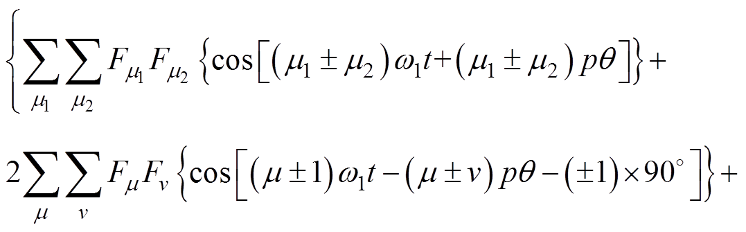
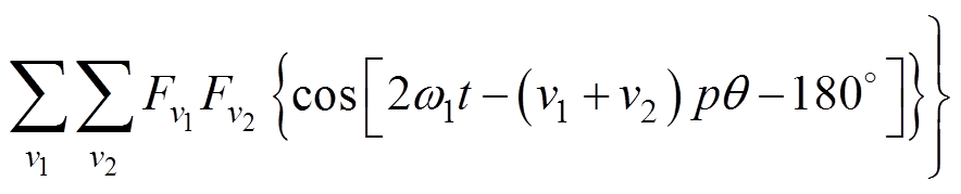
产生的总径向力波为
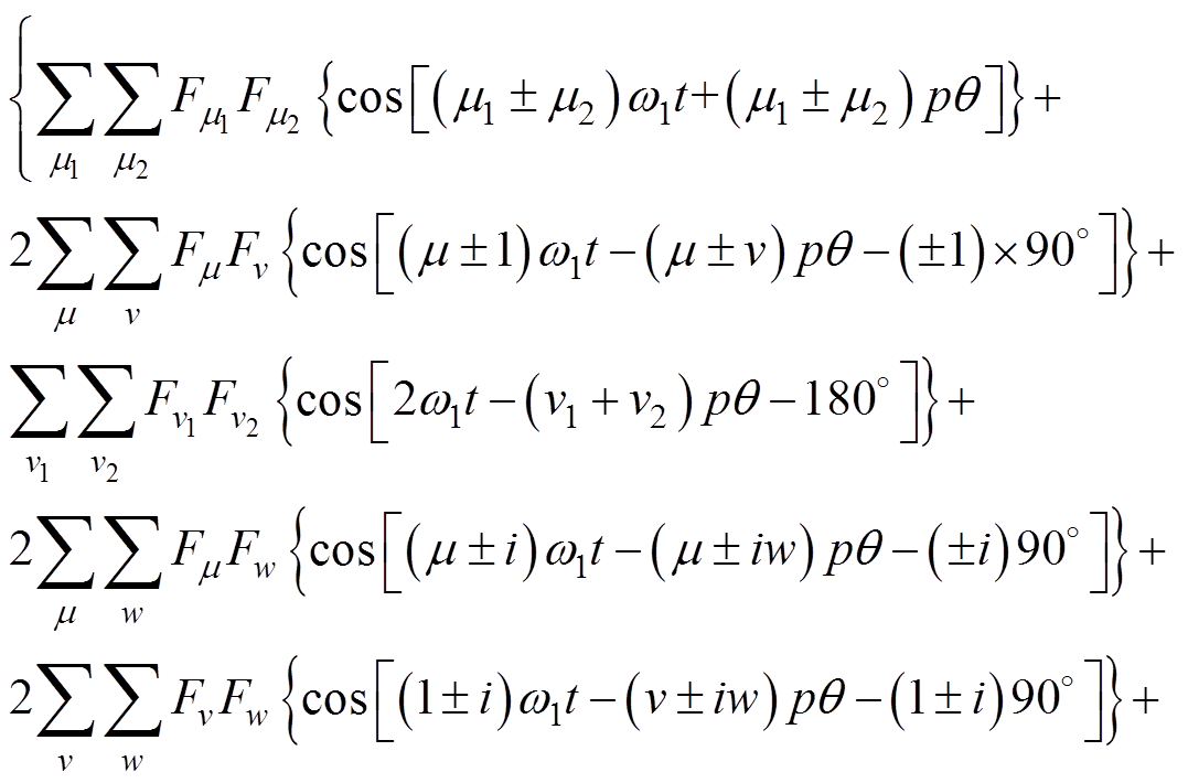
 (5)
(5)
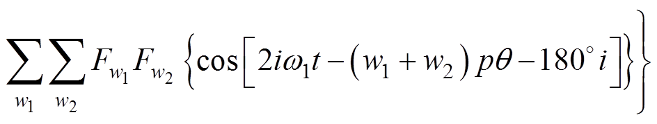
式(5)减式(3)得到i次谐波电流产生的补偿径向力波为
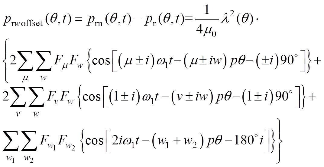 (6)
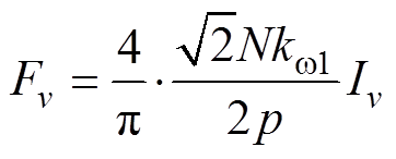
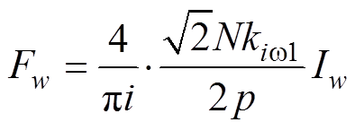
(6)如果不考虑偏心和材料的不均匀,通入的三相电流是对称的,当电机匀速稳态运行时,式(6)中三个系数[24-25]分别为
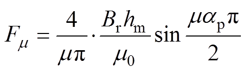 (7)
(7)
 (8)
(8) (9)
(9)
式中,Br为永磁体剩磁;ap为永磁磁极的极弧系数;m0为空气磁导率;hm为永磁体充磁方向厚度;N为每相串联匝数;Iv为电流幅值;kw1为基波磁动势的绕组因数;Iw为i次谐波电流幅值;kiw1为i次谐波电流磁动势的绕组因数。
则式(6)可以表示为
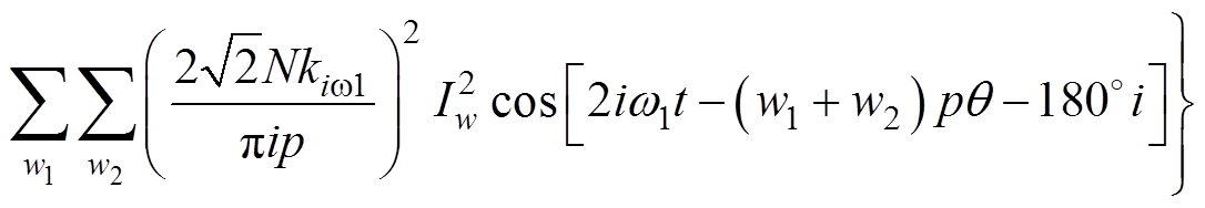 (10)
(10)要想注入谐波电流来抑制极槽振动,就必须使得注入谐波电流所产生的补偿力波与基波产生的极槽径向力波的频率相同、幅值相同、相位相差180°,所以式(10)中所有分量的频率都应该是f1的偶数倍,即注入的谐波电流频率只能是f1的奇数倍。
如果只考虑定子圆周上某固定点的振动,不考虑偏心和材料的不均匀,注入的三相电流是对称的,则式(10)中除谐波电流幅值Iw和频率iw1需要给定,其他各参数都是与电机的材料和空间结构有关的不变的量,所以当基波电流不变,注入2i+1(i= 1, 2, …)次谐波,且初始相位为0时,从式(10)得到以下结论:
(1)谐波电流幅值的大小不改变谐波电流所产生的各偶数倍频补偿力波的相位。
(2)谐波电流引起的各偶数倍频(除2iw1)补偿力波幅值与谐波电流的幅值是线性关系,由于式(10)前两项的2iw1次力波的幅值大于第三项的幅值,所以2iw1次补偿力波幅值与谐波电流幅值近似线性,其相位近似不变。
对一台85kW表贴式永磁同步电机进行Ansys仿真分析,以3、5次谐波电流为例,注入谐波电流初始相位为0时,基波电流幅值为5,谐波电流幅值从0到5变化时,3次谐波电流幅值与其产生的各倍频补偿力波幅值和相位之间的关系如图1所示。图2为5次谐波电流幅值与其产生的各倍频补偿力波幅值和相位之间的关系。
图1中,除了6倍频力波的幅值与3次谐波电流的幅值是呈近似线性以外,其他倍频力波的幅值与3次谐波电流的幅值都是线性的,3次谐波电流的幅值变化不改变各倍频(除6倍频)力波的相位;图2中,除了10倍频力波的幅值与5次谐波电流的幅值是呈近似线性以外,其他倍频力波的幅值与5次谐波电流的幅值都是线性的,5次谐波电流的幅值变化不改变各倍频(除10倍频)力波的相位。

图1 3次谐波电流幅值与其产生的各倍频补偿力波幅值和相位之间的关系
Fig.1 The relation between the amplitude of the third harmonic current and the amplitude and phase of the compensation force
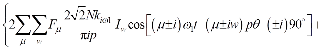
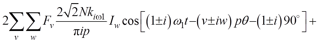
依据以上结论,当注入2i+1次谐波电流的径向补偿力波时,式(10)可以简化为

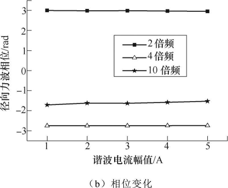
图2 5次谐波电流幅值与其产生的各倍频补偿力波幅值和相位之间的关系
Fig.2 The relation between the amplitude of the fifth harmonic current and the amplitude and phase of the compensation force
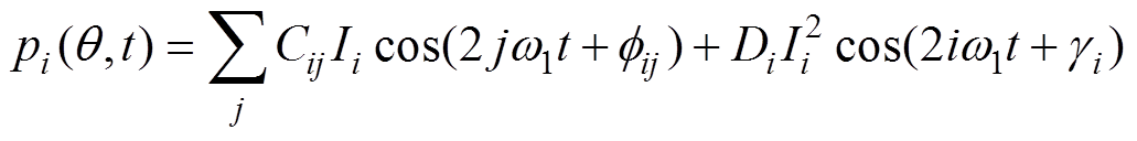 (11)
(11)式中,Ii为注入2i+1次谐波电流幅值;Cij为2jw1倍频径向补偿力波幅值系数;CijIi和 分别为2jw1倍频径向补偿力波幅值和初始相位;
 和
和 分别为2i+1次谐波电流磁场自身耦合的2iw1倍频径向补偿力波的幅值和初始相位;Cij、、Di、为待辨识的参数。
在电机正常运行的情况下,本文采用最小二乘辨识方法和牛顿迭代法,每次只注入一种频率的谐波电流对Cij、、Di、参数进行辨识,步骤如下:
(1)电机正常运行时,在线测得径向力波 。
。
(2)注入2i+1次谐波电流,在线测得径向力波 。
。
(3)将步骤(2)得到的径向力波减去步骤(1)得到的径向力波,得到补偿力波 。
。
(4)用最小二乘法[26]和牛顿迭代法的参数辨识方法辨识Cij、、Di、。
注入2i+1次谐波电流的各2jw1径向力补偿力波为
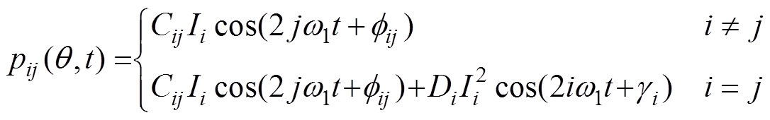 (12)
(12)为了简化辨识步骤,分成幅值和相位两个函数,有
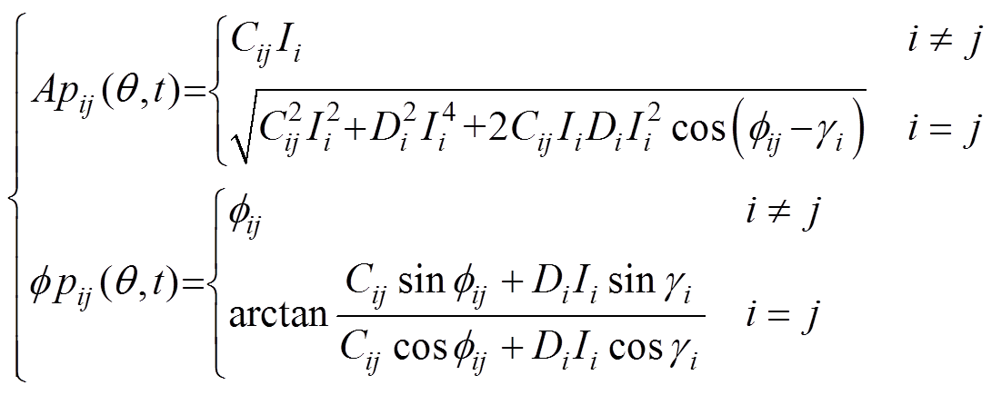 (13)
(13)
其中,待辨识参数 为
为
实际参数辨识是在离散状态下运算的,设t=kT(k=1, 2,…, N),在线检测值为
 (14)
(14)
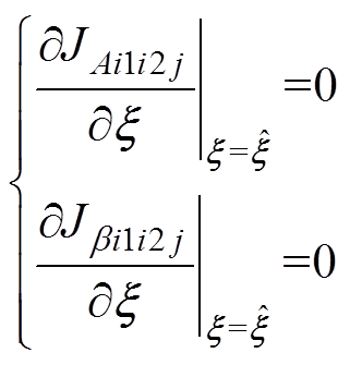
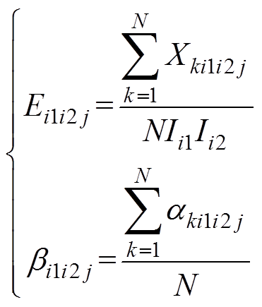
幅值和相位评价函数分别为
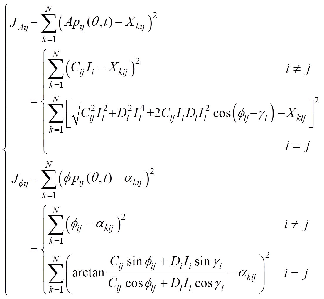 (15)
(15)根据求极值方法,对式(15)求导,得
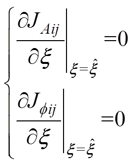 (16)
(16)
整理得
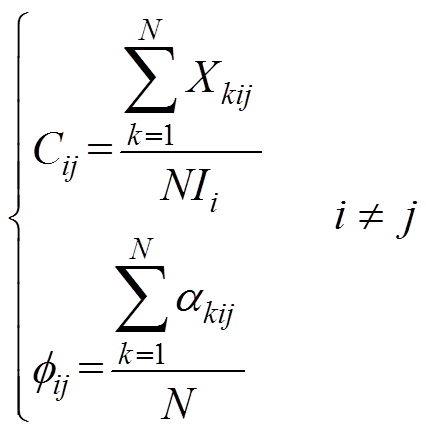 (17)
(17)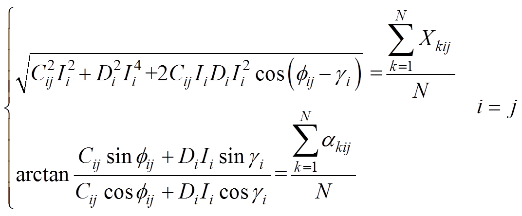 (18)
(18)
式(18)利用牛顿迭代法进行求解,得到Cij、、Di、。
当同时注入多频次谐波电流时,除各单频次补偿径向力波外,还有各频次谐波电流之间的耦合径向力波。同时注入2i1+1次谐波电流和2i2+1(i1≠i2)次谐波电流,引起的耦合的径向力波为
 (19)
(19)当电机匀速稳态运行,ki1w1和ki2w1为与电机材料和结构有关的常数。
由式(19)可知,耦合径向力波幅值与两个谐波电流的幅值都是线性关系,如图3所示,且两个谐波电流幅值的变化不改变耦合径向力波的初始相位,如图4所示。由于谐波电流之间的耦合径向力波幅值远远小于总径向力波幅值,所以存在计算误差,又由于Ansys剖分网格大小的限制,所以存在仿真误差,图3和图4结果会有偏差。
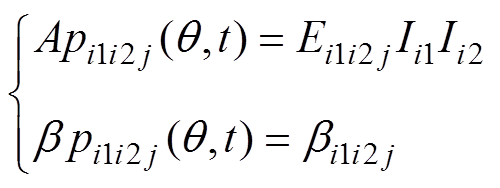
当注入2i1+1次谐波电流和2i2+1次谐波电流时,引起的耦合径向力波可以由式(19)简化为
 (20)
(20)式中,Ei1i2j和bi1i2j分别为2jw1倍频径向力波的幅值系数和初始相位,Ei1i2j、bi1i2j为待辨识的参数。

图3 耦合径向力波幅值和相位与3次谐波电流的幅值之间的关系
Fig.3 The relationship between the amplitude and phase of the coupled radial force and the amplitude of the third harmonic current
与2.2节类似,每次只注入一种频率的谐波电流进行参数辨识,步骤如下:
(1)电机正常运行时,在线测得径向力波 。
。

图4 耦合径向力波幅值和相位与5次谐波电流的幅值之间的关系
Fig.4 The relationship between the amplitude and phase of the coupled radial force and the amplitude of the fifth harmonic current
(2)注入2i1+1次谐波电流,在线测得径向力波 。
。
(3)注入2i2+1次谐波电流,在线测得径向力波 。
。
(4)同时注入2i1+1次谐波电流和2i2+1次谐波电流,在线测得径向力波 。
。
(5)按照式(20)算出双频次谐波电流的耦合径向力波 。
。
(6)用最小二乘法参数辨识方法辨识Ei1i2j、bi1i2j。
同时注入2i1+1次谐波电流和2i2+1次谐波电流的各2jw1耦合径向力波为
 (21)
(21)为了简化辨识步骤,分成幅值和相位两个函数,分别为
 (22)
(22)
其中,待辨识参数 为
为
=[Ei1i2j bi1i2j]实际参数辨识是在离散状态下运算的,设t=kT(k=1, 2,…, N),在线检测值为
 (23)
(23)
幅值和相位评价函数为
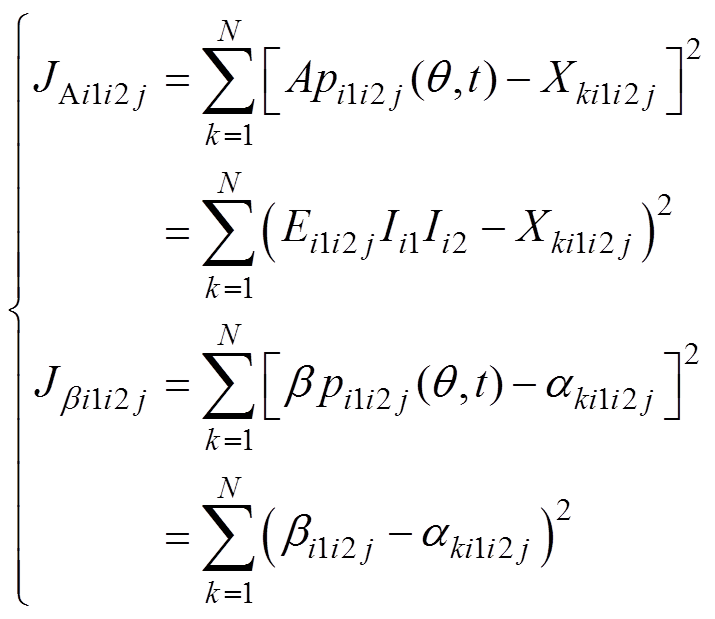 (24)
(24)根据求极值方法,对式(24)求导,得
 (25)
(25)
整理得
 (26)
(26)通过3.1节和3.2节的综合推导可知,当注入所有2i+1(i=1, 2,…, n)次谐波电流,得到的总径向力波补偿模型为
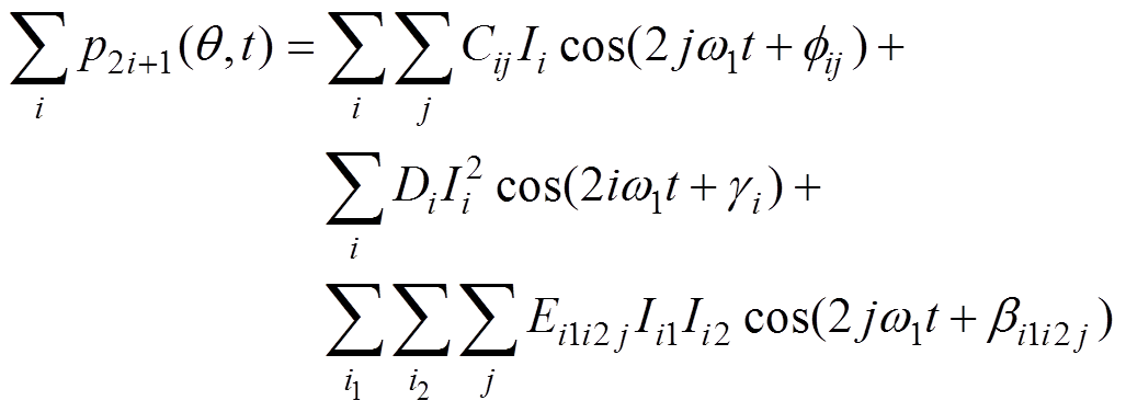 (27)
(27)样机为85kW内转子表贴式永磁同步电机,如图5所示,其主要参数见表1。
为了分析径向力波,用振动加速度传感器获取径向力波加速度。电机以转速330r/min运行,即w1=44rad/s,反向(180o相位)注入5、7次谐波电流幅值0.1A时,相电流和力波如图6和图7所示,图8为力波频谱图。从图8中可以看出,注入各频次谐波电流对各偶次径向力波都有影响,或减小或增大。单频次谐波电流注入时,谐波电流幅值与补偿力波幅值关系如图9和图10所示;双频次谐波电流注入时,各次谐波电流幅值与耦合补偿力波幅值关系如图11和图12所示。
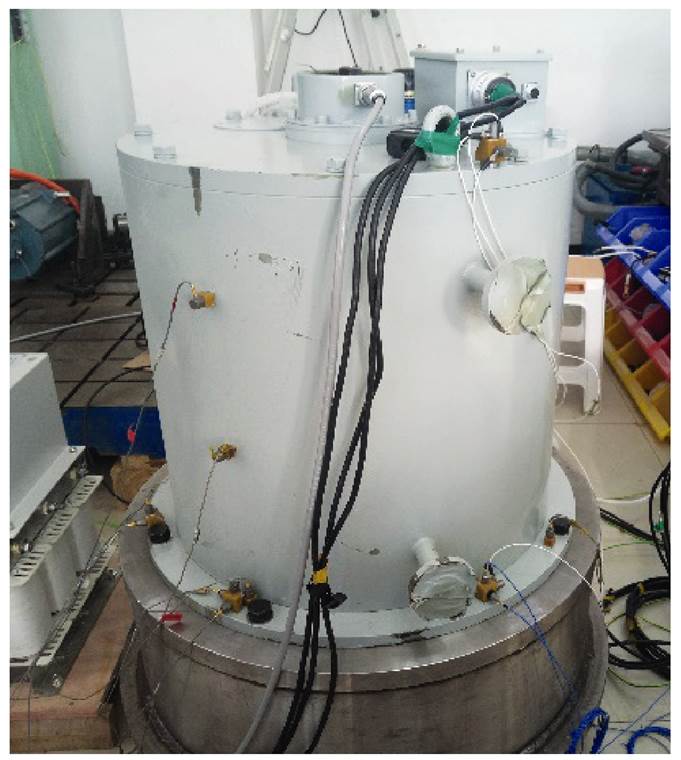
图5 85kW内转子表贴式永磁同步电机
Fig.5 85kW internal rotor surface mount permanent magnet synchronous motor
表1 永磁电机基本参数
Tab.1 Basic parameters of permanent magnet motor
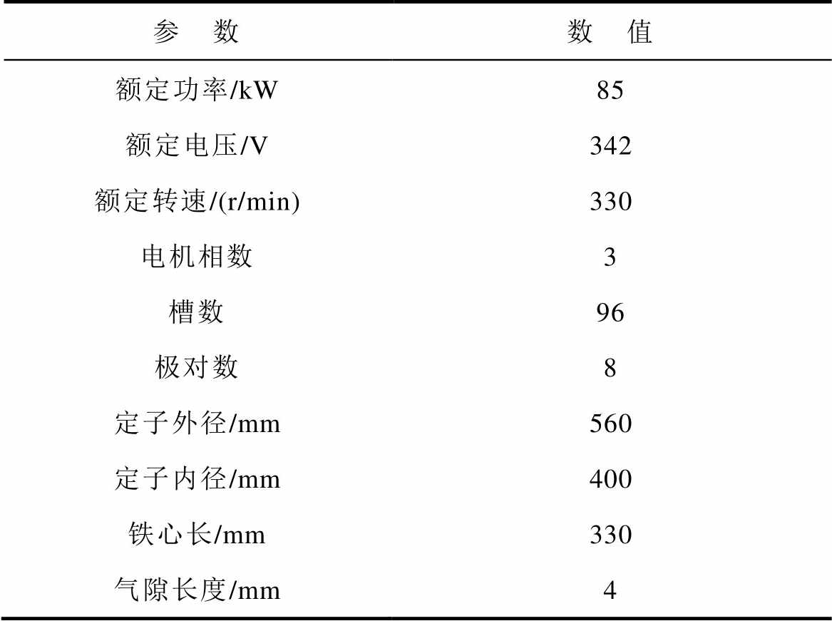
参 数数 值 额定功率/kW85 额定电压/V342 额定转速/(r/min)330 电机相数3 槽数96 极对数8 定子外径/mm560 定子内径/mm400 铁心长/mm330 气隙长度/mm4
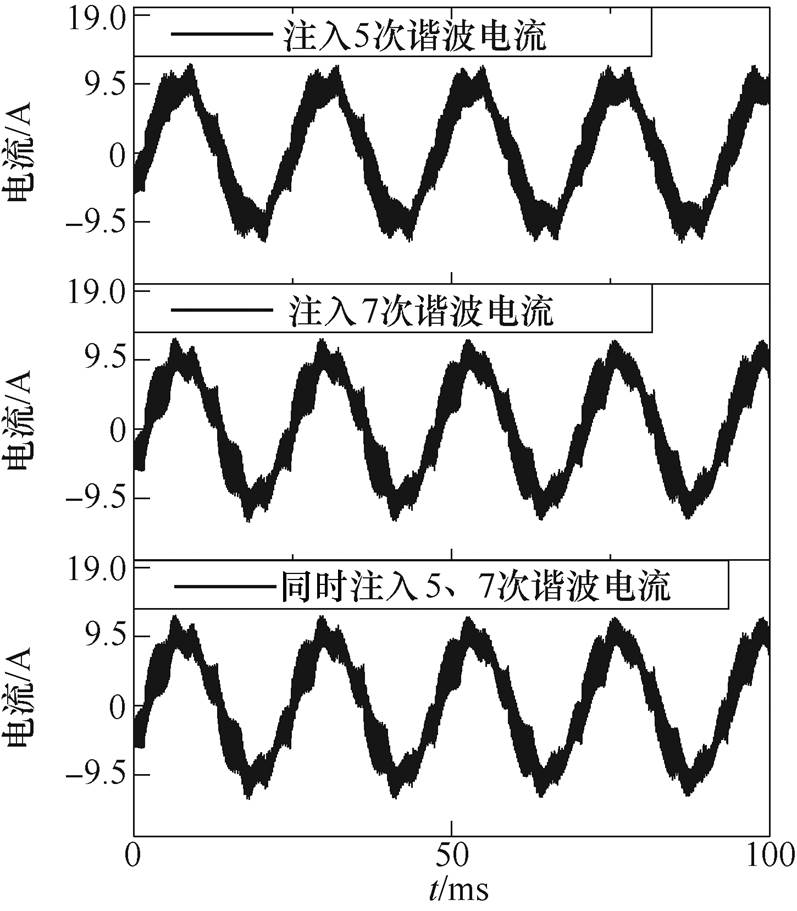
图6 无谐波电流及注入5、7次谐波电流的相电流
Fig.6 The phase current waveforms of no harmonic current and the injected fifth and seventh harmonic current
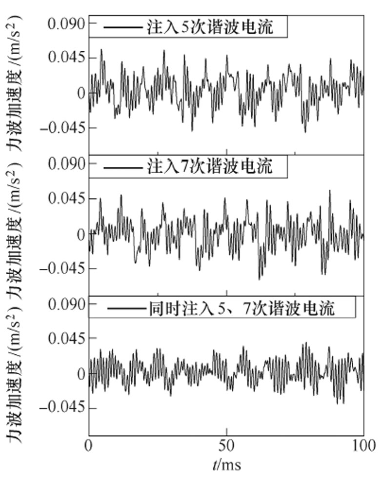
图7 无谐波及注入5、7次谐波电流的力波
Fig.7 Force wave spectrum of no harmonic current and injected fifth and seventh harmonic current
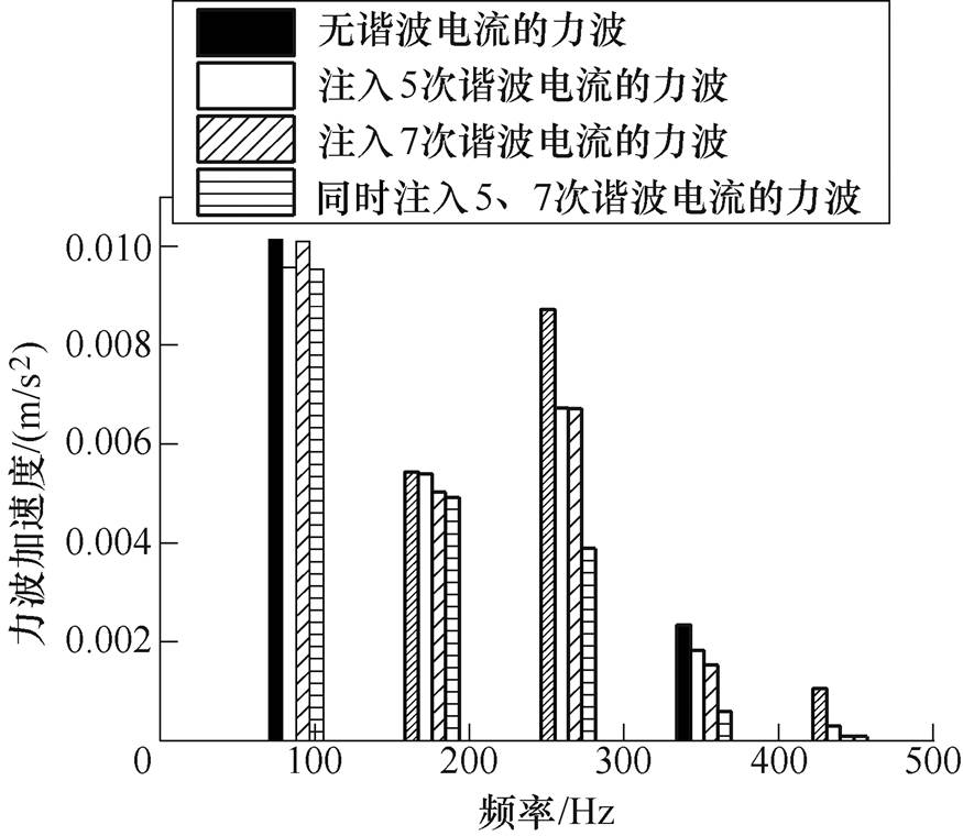
图8 无谐波和注入各频次谐波的力波频谱图
Fig.8 Force wave of No harmonic current and injected each harmonic current
分析以上数据,首先,谐波电流注入的幅值不能超过基波幅值,否则会影响电机性能;其次,单频次谐波电流对各倍频力波减小的程度不同,注入以后各倍频力波或欠减、或过减。因此,当注入单频次谐波电流无法达到减振效果时,就需要多频次谐波电流共同作用,来达到减振效果。而多频次谐波电流的注入必须以建立谐波电流与径向力波之间的关系为基础。
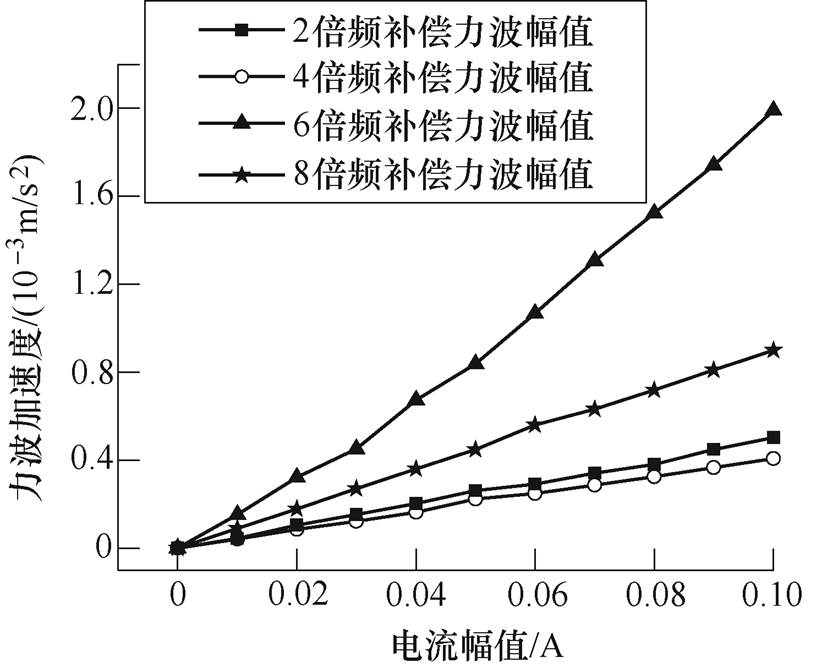
图9 5次谐波电流幅值与补偿力波幅值的关系
Fig.9 The relationship between the amplitude of the fifth harmonic current and the amplitude of the compensating force
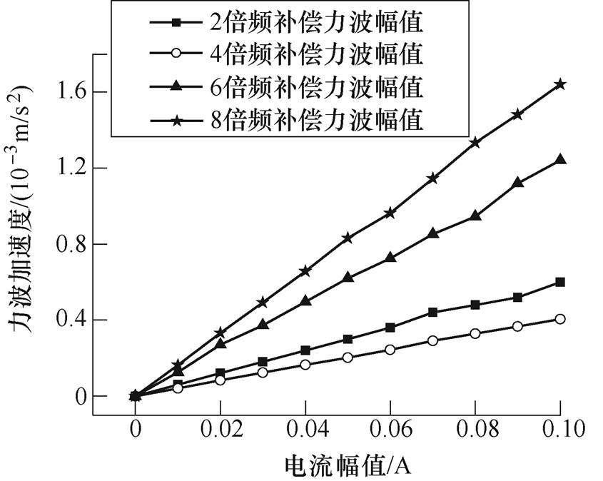
图10 7次谐波电流幅值与补偿力波幅值的关系
Fig.10 The relationship between the amplitude of the seventh harmonic current and the amplitude of the compensating force

图11 5次谐波电流幅值与耦合力波幅值的关系
Fig.11 Relationship between amplitude of fifth harmonic current and amplitude of coupling force
本文主要针对电机的低频极槽振动进行研究,所以只研究2、4、6、8倍频力波,以注入5、7次谐波电流为例,建立它们与2、4、6、8倍频补偿力波之间的关系模型,用2.2节和3.2节的步骤和式(17)、式(26)辨识出各力波参数见表2。
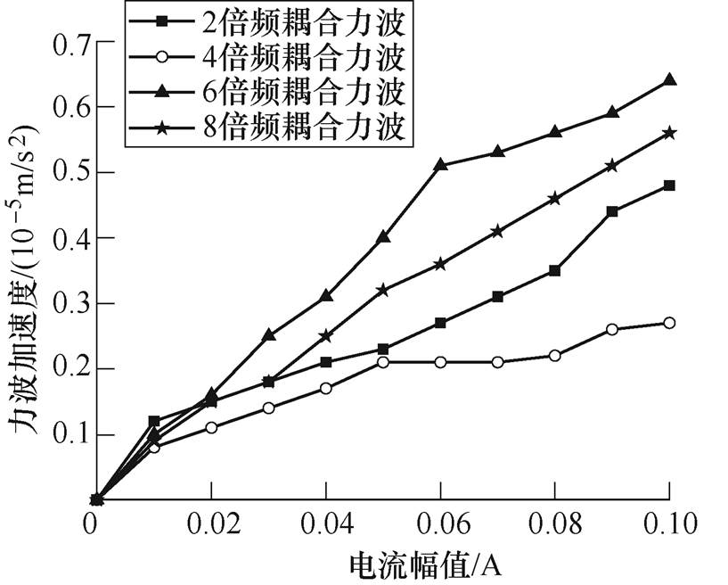
图12 7次谐波电流幅值与耦合力波幅值的关系
Fig.12 Relationship between amplitude of seventh harmonic current and amplitude of coupling force
表2 辨识得到的各力波参数
Tab.2 The identified parameters of each force wave

力波频率5次谐波电流7次谐波电流电流耦合 CijfijCijfijEi1i2jbi1i2j 2w10.005 062.990.006 04-2.630.000 80.31 4w10.004 2-2.750.004 022.520.000 932.9 6w10.018 241.80.001 234-0.40.001 81.25 8w10.009 08-2.980.016 5-2.660.001 30.27
得到补偿力波解析表达式为
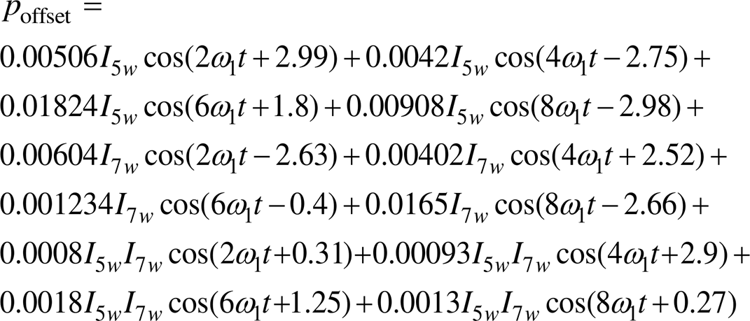
式中,I5w、I7w分别为注入的5次、7次电流谐波幅值,反向(180°相位)注入幅值为0.1A的3、5次谐波电流,总力波与计算得到的补偿力波如图13所示。
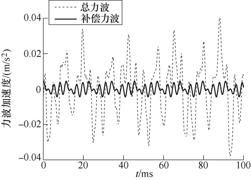
图13 总力波与计算得到的补偿力波
Fig.13 The total force wave and the calculated compensating force wave
注入前后总力波频谱变化如图14所示。

图14 源力波与补偿后的总力波频谱
Fig.14 The spectrum of source force waves and compensated force waves
从图14可以看出,本文利用解析表达式算出的力波能够有效地减小各倍频力波,尤其是6倍频以上力波削减效果很明显。
本文分别推导出表贴式三相永磁同步电机的单频次谐波电流注入的径向力波补偿模型、双频次谐波电流注入的耦合径向力波补偿模型和多频次谐波电流注入的径向力波补偿模型,并采用最小二乘法和牛顿迭代法进行参数辨识。通过Ansys仿真和样机实验验证所建模型的正确性和有效性。结论如下:
1)低频特征参数的辨识克服了补偿模型复杂的不足,计算步骤少、时间短,适合在线辨识。
2)从实验结果可以看出,采用表贴式三相永磁同步电机的低频段径向力波补偿模型得到的力波结果与仿真得到的力波结果吻合。
3)本文研究的模型为后续注入多频次谐波电流抑制表贴式三相永磁同步电机径向力波的研究打下了坚实的基础。
参考文献
[1] 李青, 杨德庆, 郁扬. 舰船低频水下辐射噪声数值计算方法对比研究[J]. 中国造船, 2017, 58(3): 114-127.
Li Qing, Yang Deqing, Yu Yang. Comparative study on numerical methods for underwater low-frequency radiation noise of ship[J]. Shipbuilding of China, 2017, 58(3): 114-127.
[2] 向万龙. 基于统计能量法的水下航行器振动分析[D]. 北京: 中国舰船研究院, 2017.
[3] 李清, 于汉, 杨德庆. 多类振动噪声源下舰船水下噪声的耦合声场计算方法[J]. 上海交通大学学报, 2019, 53(2): 161-169.
Li Qing, Yu Han, Yang Deqing. Coupled sound field calculating method for ship underwater noise excited by multiple categories of vibration and sound sources[J]. Journal of Shanghai Jiao Tong University, 2019, 53(2): 161-169.
[4] 刘刚, 张强, 毛琨. 基于电压注入的高速永磁电机谐波电流抑制方法[J]. 电机与控制学报, 2016, 20(7): 8-16.
Liu Gang, Zhang Qiang, Mao Kun. High-speed per- manent magnet synchronous motor current harmonics suppression based on voltage injection[J]. Electric Machines and Control, 2016, 20(7): 8-16.
[5] 王硕, 康劲松. 一种基于自适应线性神经网络算法的永磁同步电机电流谐波提取和抑制方法[J]. 电工技术学报, 2019, 34(4): 654-663.
Wang Shuo, Kang Jinsong. Harmonic extraction and suppression method of permanent magnet synchronous motor based on adaptive linear neural network[J]. Transactions of China Electrotechnical Society, 2019, 34(4): 654-663.
[6] 贾红云, 程明, 花为, 等. 基于电流谐波注入的磁通切换永磁电机定位力矩补偿方法[J]. 中国电机工程学报, 2009, 29(27): 83-89.
Jia Hongyun, Cheng Ming, Hua Wei, et al. Cogging torque compensation for flux-switching permanent magnet motor based on current harmonics injection[J]. Proceedings of the CSEE, 2009, 29(27): 83-89.
[7] 刘和平, 刘庆, 张威, 等. 电动汽车用感应电机削弱振动和噪声的随机PWM控制策略[J]. 电工技术学报, 2019, 34(7): 1488-1495.
Liu Heping, Liu Qing, Zhang Wei, et al. Random PWM technique for acoustic noise and vibration reduction in induction motors used by electric vehicles[J]. Transactions of China Electrotechnical Society, 2019, 34(7): 1488-1495.
[8] 廖勇, 甄帅, 刘刃, 等. 用谐波注入抑制永磁同步电机转矩脉动[J]. 中国电机工程学报, 2011, 31(21): 119-127.
Liao Yong, Zhen Shuai, Liu Ren, et al. Torque ripple suppression of permanent magnet synchronous motor by the harmonic injection[J]. Proceedings of the CSEE, 2011, 31(21): 119-127.
[9] 周明磊, 游小杰, 王琛琛, 等. 特定次谐波消除调制方式的谐波特性分析[J]. 电工技术学报, 2013, 28(9): 11-20.
Zhou Minglei, You Xiaojie, Wang Chenchen, et al. Harmonic analysis of selected harmonic elimination pulse width modulation[J]. Transactions of China Electrotechnical Society, 2013, 28(9): 11-20.
[10] Zhu Chong, Zeng Zhiyong, Zhao Rongxing. Com- prehensive analysis and reduction of torque ripples in three-phase four-switch inverter-fed PMSM drives using space vector pulse-width modulation[J]. IEEE Transactions on Power Electronics, 2017, 32(7): 5411-5424.
[11] 史友情, 陶彩霞. 双Y移30°六相永磁同步电机谐波电流抑制技术[J]. 电机与控制应用, 2017, 44(3): 90-95.
Shi Youqing, Tao Caixia. Techniques to restrain harmonics of six-phase permanent magnet synchronous motor with two Y-connected windings displaced by 30°[J]. Electric Machines and Control Application, 2017, 44(3): 90-95.
[12] 李毅拓, 陆海峰, 瞿文龙, 等. 基于前馈补偿的永磁同步电机电流谐波抑制方法[J]. 清华大学学报:自然科学版, 2012, 52(3): 362-366.
Li Yituo, Lu Haifeng, Qu Wenlong, et al. PMSM current harmonics suppression based on feedforward compensation[J]. Journal of Tsinghua University: Science and Technology, 2012, 52(3): 362-366.
[13] Jin Xinhai, Li Baisong, Xu Dianguo. A current harmonics suppression method for permanent magnet synchronous motor drives[C]//IEEE Transportation Electrification Conference and Expo, Asia-Pacific, Harbin, 2017: 1-6.
[14] Gao Jian, Wu Xuan, Huang Shoudao, et al. Torque ripple minimisation of permanent magnet synchronous motor using a new proportional resonant controller[J]. IET Power Electronics, 2017, 10(2): 208-214.
[15] 高骏, 王磊, 周文, 等. 双馈风电机组电网背景谐波运行与谐波抑制策略研究[J]. 电力系统保护与控制, 2016, 44(23): 164-169.
Gao Jun, Wang Lei, Zhou Wen, et al. Study on operating behavior and suppression strategy of doubly-fed induction generators wind turbine under harmonic grid voltage conditions[J]. Power System Protection and Control, 2016, 44(23): 164-169.
[16] 麦志勤, 肖飞, 刘计龙, 等. 基于准比例谐振级联PI的双三相永磁同步电机谐波电流抑制策略[J]. 电工技术学报, 2018, 33(24): 5751-5759.
Mai Zhiqin, Xiao Fei, Liu Jilong, et al. Harmonic current suppression strategy of dual three-phase permanent magnet synchronous motor based on quasi proportional resonant cascading PI[J]. Transactions of China Electrotechnical Society, 2018, 33(24): 5751- 5759.
[17] 李帅, 孙立志, 刘兴亚, 等. 永磁同步电机电流谐波抑制策略[J]. 电工技术学报, 2019, 34(1): 87-96.
Li Shuai, Sun Lizhi, Liu Xingya, et al. Current harmonics suppression strategies of permanent magnet synchronous motor[J]. Transactions of China Electro- technical Society, 2019, 34(1): 87-96.
[18] 武永燎, 李红, 宋欣达, 等. 基于改进型重复控制器的永磁同步电机电流谐波抑制方法研究[J]. 电工技术学报, 2019, 34(11): 2277-2286.
Wu Yongliao, Li Hong, Song Xinda, et al. Suppressionof harmonic current in permanent magnet synchronous motor using improved repetitive controller[J]. Transa- ctions of China Electrotechnical Society, 2019, 34(11): 2277-2286.
[19] Pramanick S, Karthik R S, Azeez N A, et al. A harmonic suppression scheme for full speed range of a two-level inverter fed induction motor drive using switched capacitive filter[J]. IEEE Transactions on Power Electronics, 2017, 32(3): 2064-2071.
[20] Li Lei, Lee Kok-Meng, Bai Kun, et al. Inverse models and harmonics compensation for suppressing torque ripples of multiphase permanent magnet motor[J]. IEEE Transactions on Industrial Electronics, 2018, 65(11): 8730-8739.
[21] Lin Fu, Zuo Shuguang, Wu Xudong. Electromagnetic vibration and noise analysis of permanent magnet synchronous motor with different slot-pole com- binations[J]. IET Electric Power Applications, 2016, 10(9): 899-908.
[22] 赵文峰, 赵博, 徐永向. 磁场干涉对永磁电机电磁力特性影响研究[J]. 电机与控制学报, 2018, 22(2): 33-40.
Zhao Wenfeng, Zhao Bo, Xu Yongxiang. Research of permanent magnet motors cogging force affected by interferential magnetic field[J]. Electric Machines and Control, 2018, 22(2): 33-40.
[23] 左曙光, 刘晓璇, 于明湖, 等. 永磁同步电机电磁振动数值预测与分析[J]. 电工技术学报, 2017, 32(1): 159-167.
Zuo Shuguang, Liu Xiaoxuan, Yu Minghu, et al. Numerical prediction and analysis of electromagnetic vibration in permanent magnet synchronous motor[J]. Transactions of China Electrotechnical Society, 2017, 32(1): 159-167.
[24] 陈益广, 潘玉玲, 贺鑫. 永磁同步电机分数槽集中绕组磁动势[J]. 电工技术学报, 2010, 25(10): 30-36.
Chen Yiguang, Pan Yuling, He Xin. Magnetomotive force in permanent magnet synchronous machine with concentrated fractional-slot winding[J]. Transactions of China Electrotechnical Society, 2010, 25(10): 30-36.
[25] 张冉. 表面式永磁电机电磁激振力波及其抑制措施研究[D]. 济南: 山东大学, 2011.
[26] 罗琴琴, 苏建徽, 林志光, 等. 基于递推最小二乘法的虚拟同步发电机参数辨识方法[J]. 电力系统自动化, 2019, 43(1): 215-221.
Luo Qinqin, Su Jianhui, Lin Zhiguang, et al. Parameter identification method for virtual synchronous gener- ators based on recursive least squares algorithm[J]. Automation of Electric Power Systems, 2019, 43(1): 215-221.
The Model of Pole Slot Radial Force Wave Compensation for Surface-Mounted Three-Phase Permanent Magnet Synchronous Motor and Parameter Identification
Abstract In the radial force wave modulation of motor, harmonic current injection method is an effective method. In this paper, according to Maxwell stress tensor method, firstly, the spatial and temporal distribution model of the radial force wave in the pole slot generated by the electromagnetic action of the surface-mounted three-phase permanent magnet synchronous motor (PMSM) was deduced to determine the harmonic current frequency with compensation effect. Secondly, the single-frequency harmonic current injection compensation model was derived, and the least square method and Newton iteration method were used for parameter identification. Thirdly, the coupled radial force wave model was derived and the least square method was used to identify the parameters. Finally, the compensation model of multifrequency harmonic current injection was deduced. The model is verified by Ansys simulation and prototype experiment.
keywords:Surface-mounted permanent magnet synchronous machines (SPMSM), harmonic current injection, radial force wave, parameter identification
中图分类号:TM351
DOI: 10.19595/j.cnki.1000-6753.tces.191442
收稿日期 2019-11-09
改稿日期 2020-01-15
夏加宽 男,1962年生,教授,博士生导师,研究方向为永磁电机振动分析与抑制。E-mail: xiajk@sut.edu.cn
康 乐 女,1983年生,博士研究生,讲师,研究方向为永磁电机振动分析与抑制。E-mail: kangle_mail@163.com(通信作者)
(编辑 崔文静)