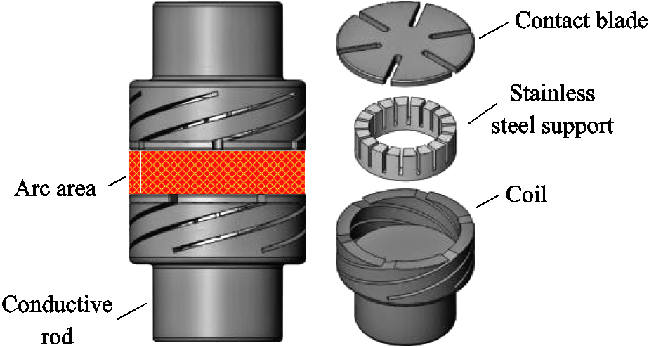
Fig.1 The structure of cup-type AMF vacuum interrupter
Abstract Characteristics of axial magnetic field (AMF) vacuum interrupters in intermediate-frequency (IF, 400-800Hz) power system of more electric aircraft is researched in this paper. The AMF distribution is solved by Maxwell. It can be concluded by the calculation as follows: In the process of current change, the axial magnetic field changes slower in the central region than in other regions. The peak area of the magnetic field is located between the interlaced slots, and there is a significant residual magnetic field in the center area at current zero. When the frequency increases, the eddy effect is so serious that the magnetic flux density of the AMF decreases. For the center point, the residual magnetic field is stronger and the lag phase is bigger on account of the frequency increase, which will prevent the arc plasmas from diffusing. The eddy effect can be reduced by adding the number of slot in the contact blade. The maximum of the magnetic flux density is increased approximately linearly by adding the rotation angle of contact. The influence of magnetic field hysteresis on the breaking capacity of the vacuum interrupter is verified by experiments including arc appearance and arc voltage.
Keywords: More electric aircraft, axial magnetic field, vacuum interrupters, intermediate frequency, eddy current effect
In recent years, more-electric/all-electric aircraft has become the focus of research around world. Compared to a constant frequency power supply system in traditional aircraft, electricity is generated by a frequency-varying generator and the current frequency is in the range of 360-800Hz in the intermediate frequency (IF) power supply system, such as in A380, B787 and C919[1-2]. As the frequency and current increase, the interruption process becomes difficult, then a new type circuit breaker is required to ensure the electrical safety of the aircraft[3-4]. Vacuum circuit breakers have been widely used in medium/low voltage power systems, and are potentially suitable for use in the IF power supply system[5-9].
For the axial magnetic field (AMF) type vacuum interrupter, an axial magnetic field will be generated when current is through the contact coil, which can improve the interruption ability of the vacuum interrupter[10]. The research shows that an appropriate AMF can make the arc diffuse in the high current mode. As a result, the arc energy and the degree of ablation on the contact surface are reduced[11-13].
At present, numerical method is usually used to study the magnetic field distribution in electrical equipment. 3D finite element method has been used to analyze the magnetic field characteristics of the AMF interrupter and the calculated results were very close to the measured results[14-15]. Liu Zhiyuan analyzed AMF distribution in slot-type axial magnetic field contacts with and without iron plates, using commercial 3D FEM electromagnetic field simulation software Maxwell 3D[16]. Shi Zongqian investigated the influence of the distribution of AMF on high current vacuum arc with three pairs of specially designed testing electrodes generating a conventional bell-shaped AMF profile and different saddle-shaped AMF distributions. The transient AMF distribution was computed by a commercial software Ansys[17]. A. Henon studied the interruption ability of vacuum circuit breakers with AMF. The numerical model involves three-dimensional AMF simulations and the experimental study evaluates their performance in short-circuit interruption tests. The calculations are analyzed for AMF distribution[18].
The above research results mainly focus on the power frequency, and do not involve the situation when the frequency is increased to 360-800Hz. The AMF distribution in vacuum interrupter in IF is studied in this paper, and magnetic flux density at current peak (CP) and current zero (CZ) moment are paid attention. Considering the simulation and experimental results, eddy current effect and current interruption ability influenced by frequency is analysed. The effect on magnetic field hysteresis and maximum value of magnetic induction intensity by contact structure, such as the number of contact blade slots and the angle of cup coil, is also analyzed.
The structure of cup-type AMF vacuum contact is shown in Fig.1. The AMF contact consists of conductive rod, coil, contact blade and stainless steel support. The arc area is between the two contacts.
Fig.1 The structure of cup-type AMF vacuum interrupter
The main structural parameters of the cup-type AMF contact are shown in Tab. 1, and γ = π/3 and n = 6 is chosen as a basic contact.
Tab.1 Parameters for AMF Interrupters
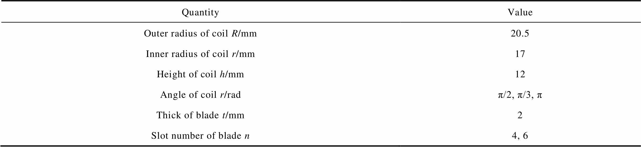
QuantityValue Outer radius of coil R/mm20.5 Inner radius of coil r/mm17 Height of coil h/mm12 Angle of coil r/radπ/2, π/3, π Thick of blade t/mm2 Slot number of blade n4, 6
In this paper, Maxwell 3D electromagnetic field finite element module in ANSYS is used to analyze the magnetic field characteristics in the AMF contact[19]. The current frequency is 400-800Hz, and the effective value is 1kA. The contact blade material is CuCr50 and the electrical conductivity is 1.044×10⁷S/m[16]. It is supposed that the arc is a cylinder with the same diameter to contact diameter and the same height to separation distance, and the arc conductivity is 400S/m. The selection is based on the experimental results of IF vacuum arc: as the contact diameter is 41mm and the separation is 3mm, the maximum arc voltage is about 60V when current is 10kA [5]. The calculation field is 10 times the size of the model, and the simulation is terminated when the error criterion of calculation matrix is set to less than 1% in the software.
When the current frequency is 400Hz, the AMF distribution at CP moment is shown in Fig.2, in which point Q refers to the center of the magnetic field, and point P refers to the maximum magnetic flux density. The line between P and Q is a specified observation diameter.

Fig.2 AMF distribution at CP moment (f=400Hz)
It can be seen from the simulation results that the magnetic flux density in the contact center is significantly lower than that in the surrounding area at CP moment. There are six peak areas, which must be related to the form of slots on the surface of contact blade and the staggered placement of contacts (see Fig. 1). As the current flows along the shortest path, the slot shortens the conduction path of the eddy current and the eddy current decreases. Therefore, the magnetic flux intensity of the AMF between the two slots is higher and the delay phase is less. However, in the middle of the contact blade, the eddy current has a large closed conduction path, and the AMF at this area is greatly affected by the eddy current, with low magnetic flux density and large delay phase. The distribution of this multi-peak region may be the reason that makes the cathode spots and arc columns appear multi-distribution[5-6].
Fig.3 shows the AMF distribution at the CZ moment with current frequency of 400Hz.
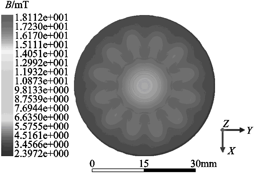
Fig.3 AMF distribution in middle plane at CZ moment (f = 400Hz)
As at CZ moment, there are 13 peak areas of magnetic flux density in the middle plane, among which 12 are in two adjacent slots where the contact is staggered, and 1 is in the center. B is higher in the central peak area. Fig.4 shows the magnetic flux density in the middle plane of P-Q diameter at different current phases.
It can be seen that, before the current peak, the AMF of each point in P-Q diameter increases with the increase of current. However the increase rate of the center is slow and the B is lower than that of other regions. At CP moment, the maximum B at point P reaches 15.94mT, and at this time, B of point Q is only 10.53mT. After CP, the further away from the center, the faster the AMF decreases, where B is almost zero. In the center, the AMF decrease slowly and there is residual magnetic field, which is consistent with Fig.3. The residual B at point Q is about 3.67mT. The change process also indicates that the magnetic field of the contact center is the most affected by the eddy current, and the hysteresis of AMF is the most obvious. In the interruption process, residual plasmas in arc gap will be under the control of residual magnetic field over a long phase and are difficult to spread quickly at IF. Moreover, if the residual magnetic field is strong, the interruption may be failed under the transient recovery voltage (TRV) after CZ [20-21].
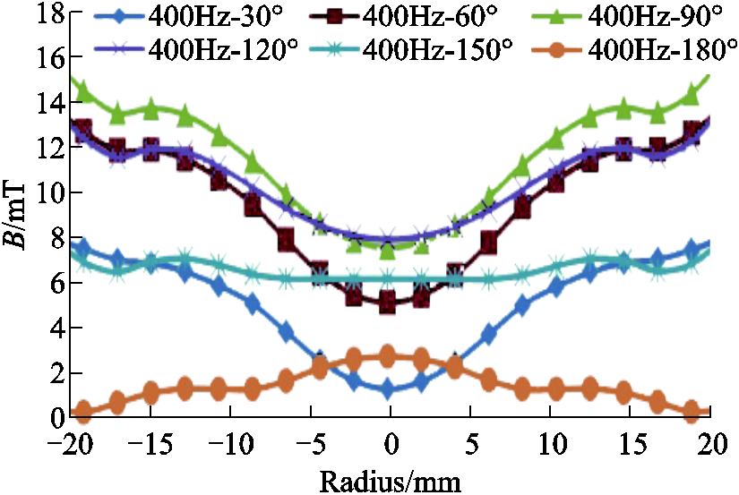
Fig.4 Magnetic flux density of P-Q diameter at different current phases
When the current frequency increases from 400Hz to 800Hz, the distribution of AMF is similar to that at 400Hz. The effect of frequency on the center point Q is shown in Fig.5.
With the frequency increases, the hysteresis of AMF is much more obvious. When the frequency is 400Hz, the residual magnetic flux density of Q is 2.80mT at CZ, and the hysteresis phase is about 20°. When the frequency is 800Hz, the residual magnetic flux density of Q is 3.65mT, and the hysteresis phase is much higher than 30°. And the effect of frequency on point P is shown in Fig.6.
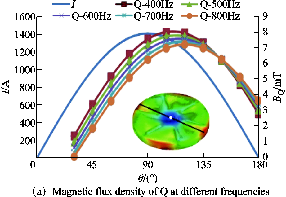
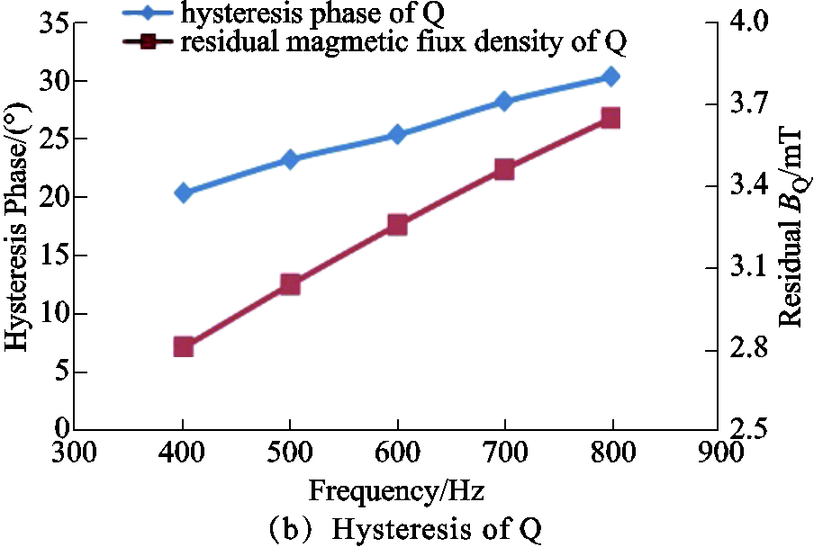
Fig.5 Magnetic flux density of Q

Fig.6 Magnetic flux density of P
With the frequency increases, the maximum value of P reduces. When the frequency is 400Hz, the maximum magnetic flux density of P is 15.94mT, and when the frequency is 800Hz, the maximum value of P is 15.72mT.
It can be seen that as the current frequency increases, the eddy current effect of the AMF will be stronger, causing the magnetic flux density of the eddy current magnetic field much stronger. In order to maintain a vector synthesis relationship, the amplitude of B decrease, and the hysteresis increases. Therefore, the eddy current effect and the hysteresis phenomenon will be strengthened by the increase of frequency.
Interruption ability experiment is carried out in AMF type vacuum interrupter. Vacuum circuit breaker of AMF type with contact materials of CuCr50 and a diameter of 41mm is selected for experiment in this section, with an open distance of 3mm. During the experiment, the current frequency is changed, and the current peak values of successful and failed breaking at different frequencies are obtained, as shown in Tab.2. The Isuccess column in Tab.2 indicates the maximum first-half current peak value of the successful breaking whereas the Ifailed column represents the current peak value when the breaking fails. For each frequency, the limit breaking test is carried out for more than 10 times. It should be noted that when the current frequency is 500Hz and current peak is 16.5kA. Sometimes the breaking is successful and sometimes it isn’t. The current value 16.5kA is considered to be the critical value of breaking. There is a similar situation for 15.5kA at 600Hz.
Tab.2 Results of interruption experiment at different frequency

f/HzIsuccess/kAIfailed/kA 36019.922.4 50016.516.5 60015.515.5 68014.415.0 85013.314.0
As shown in Fig.7a, Isuccess and Ifailed at different frequencies are represented by curves with symbol  and
and  , respectively; then the limit interruption current must be between the curves and .It can be concluded that with the increase of frequency, the limit breaking ability of AMF type vacuum interrupter decreases. From the macroscopic aspect, the interruption process is determined by the competition between the rise rate of recovery voltage (RRRV) and the rise rate of dielectric strength (RRDS). The RRDS is related to the hysteresis of the AMF. This indicates that the residual AMF caused by the increase of frequency hinders the plasma diffusion at CZ, which may be the reason why the breaking ability decreases.
Fig.7b shows the current and arc image of the vacuum arc at a frequency of360Hz. tD on the time axis represents the current zero-crossing moment. When the current crosses zero, the post-arc discharge channel can be observed from the arc image, and the post-arc current can be clearly observed in the current curve. This is because the magnetic field hysteresis caused by the eddy current effect hinders the diffusion of the remaining plasma. A similar phenomenon can also be found in the current and arc image of the 500Hz vacuum arc as shown in Fig.7c.

Fig.7 Interruption experiment at different frequency (AMF, CuCr50, 41mm)
The eddy effect will cause a magnetic field hysteresis. As the cycle time is changed with variation in frequency, the delay time is not sufficient to explain the hysteresis. Thus, in this paper, current phase θ, is introduced to analyze the AMF distribution with the same instantaneous current value but with different frequency. For example, current phase is π/2 (90°) at CP time. The current is given by
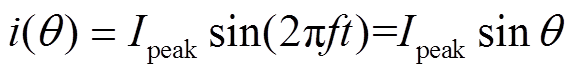 (1)
(1)where Ipeak is the current peak, f is the frequency and θ is the current phase. The AMF, B, in the contact gap is related to the current magnetic field Bi, generated by the current i, and eddy current magnetic field Be, generated by the eddy current ie.
According to Maxwell's equations, if displacement current is not taken into account, then there will be
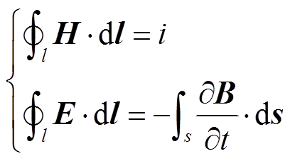 (2)
(2)As known from Equ.(2), the current i, which flows through the contacts, is in the same phase as the current magnetic field Bi. The eddy current ie, is inducted by AMF and the eddy current magnetic field, Be, lags behind B by π/2. The composition of the AMF is shown in Fig. 8, in which the angle, α, indicates the phase by which the current magnetic field Bi, lags behind the AMF B.
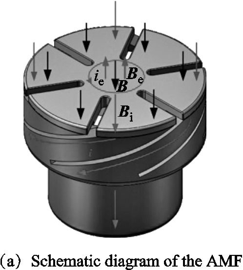
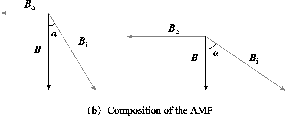
Fig.8 The AMF generated by the contacts
While the current frequency is constant and the amplitude increases, Bi and Be will increase in proportion; thus the hysteresis phase, α, is constant. However, if the current amplitude is constant and the frequency increases, the amplitude of Bi is constant and the amplitude of Be increases. To maintain a vector synthesis relationship, the amplitude of B must decrease, as well as the hysteresis phase α must increase, as displayed in Fig.8b. Therefore, the eddy current effect and the hysteresis phenomenon will be strengthened by the increase of frequency.
The AMF type vacuum interrupters with 6 and 4 slots are displayed in Fig.9.
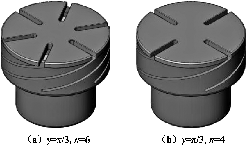
Fig.9 AMF type vacuum interrupters with 6 and 4 slots
As the current flows along the shortest path, the slot will shorten the conduction path of the eddy current. The slot number of contact blade will affect the distribution of AMF. When the current frequency is 400 Hz and the slot number 4, the AMF distribution is shown in Fig.10.
Compared with the vacuum interrupter with 6 slots, the peak area of magnetic flux density reduces from 6 to 4 at CP moment. While at CZ, it decreases from 13 to 9. It indicates that the number of peak areas of AMF is related to the slot number and staggered placement of contacts. And in Fig.11, the effect of frequency change on the B at the center point Q and P is shown.
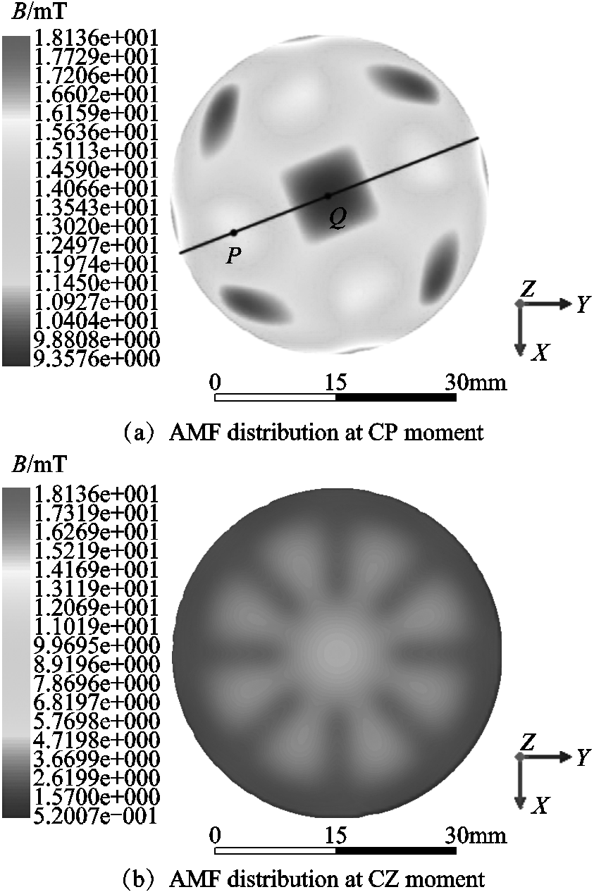
Fig.10 AMF in the middle plane (f = 400Hz, n = 4)
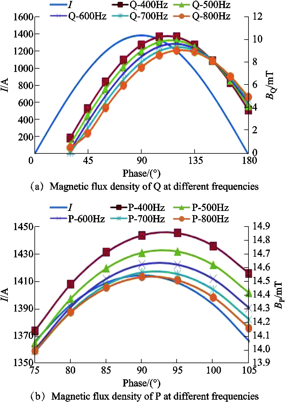
Fig.11 Magnetic flux density ofQ and P at different frequencies
As the frequency increases, the hysteresis of AMF is much more obvious. When the frequency is 400Hz, the residual magnetic flux density BQr ofQis 3.88mT at CZ, and the hysteresis phase is about 20°. When the frequency is 800Hz, the residual magnetic flux density BQr ofQ is 5.00mT, and the hysteresis phase is much higher than 35°. As the frequency is 400Hz, the maximum magnetic flux density of P is 14.85mT, and when the frequency is 800Hz, the maximum value of P is 15.53mT. Compared with the data in 2.3, when the slot number of blade is reduced from 6 to 4, as shown in Tab. 3, for the center point Q, the hysteresis is much more obvious at CZ. For the point P, the maximum value of magnetic flux density decreases. It can be seen that the decrease of the slot number makes the eddy effect more obvious.
Tab.3 Magnetic flux density for Q and P
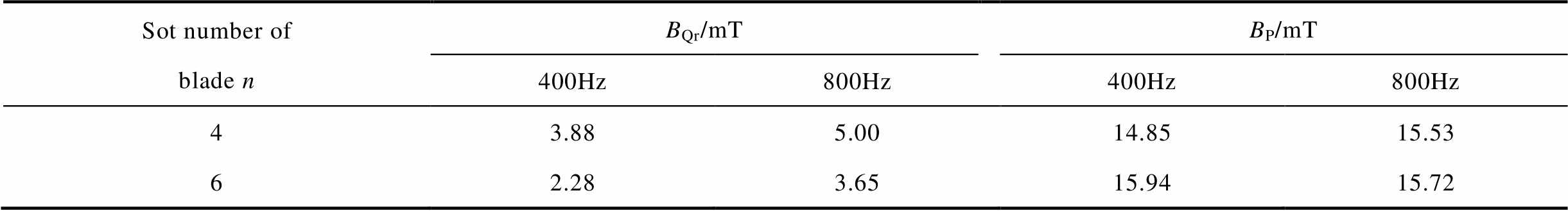
Sot number of blade nBQr/mTBP/mT 400Hz800Hz400Hz800Hz 43.885.0014.8515.53 62.283.6515.9415.72
The AMF type vacuum interrupters with γ = π/2, π/3, π are displayed respectively in Fig.12.

Fig.12 AMF type vacuum interrupters with γ = π/2, π/3, π
When the current frequency is 400Hz and γ = π/2 and π, the AMF distribution at CP are shown in Fig.13.
As can be seen from Fig.13, the rotation angle of the coil affects the maximum value of the AMF. Then the relation between the maximum value of magnetic flux density and rotation angle at CP moment can beobtained, as shown in Fig.14. With γ increases, the maximum value of the magnetic induction intensity increases approximately linearly, and the change trend is independent of frequency. For example at 400Hz, the maximum magnetic flux density is 13.42mT for γ = π/2, and the maximum magnetic flux density is 21.38mT for γ = π.
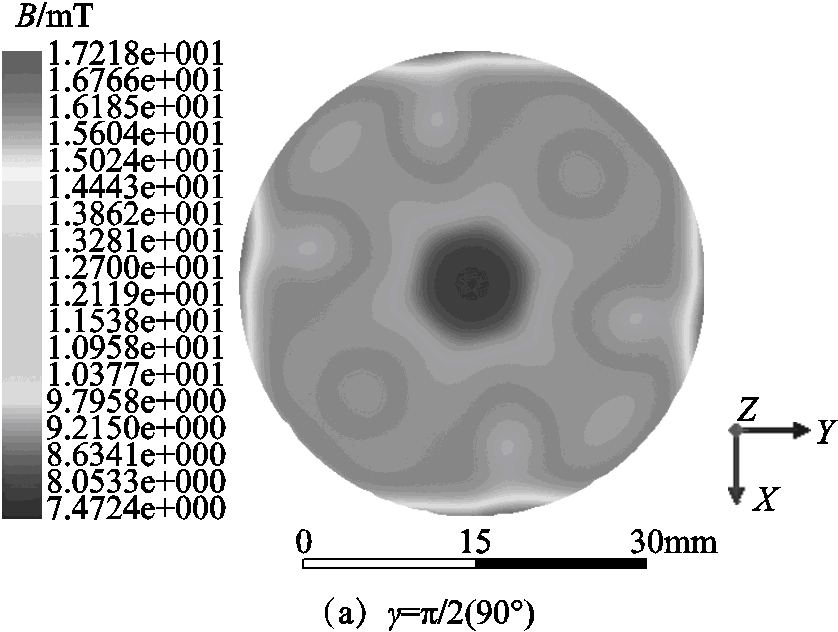

Fig.13 AMF in the middle plane at CP (f =400Hz)
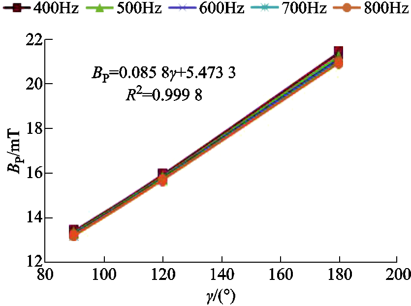
Fig.14 Relation between the maximum value of magnetic flux density and rotation angle of coil
The AMF distribution in vacuum interrupter in IF (400-800Hz) system of more electric aircraft is studied in this paper.
1) In the process of current variation, the change of magnetic field in the central region lags behind that in other regions. At CP moment, there are peak areas of magnetic flux density where the contact slot is staggered. And there is obvious residual magnetic field in the central area at CZ.
2) As the frequency increases, the eddy effect becomes more obvious, weakening the magnetic induction intensity of the AMF. For the center point, the frequency increase leads to the increase of residual magnetic field at CZ, and the hysteresis phase of magnetic field is much bigger. The effect of magnetic field hysteresis on breaking ability is verified by experiments.
3) The eddy effect can be reduced by increasing the slot number of blade. When the rotation angle of the coil is increased, the maximum magnetic flux density in the middle plane increases approximately linearly.
Reference
[1]Zhang Zhuoran, Geng Weiwei, Liu Ye, et al. Feasibility of a new ironless-stator axial flux permanent magnet machine for aircraft electric propulsion application[J]. CES Transactions on Electrical Machines and Systems, 2019, 3(1): 30-38.
[2]He Yong, Zhao Wenxiang, Tang Hongyu, et al. Auxiliary teeth design to reduce short-circuit current in permanent magnet generators[J]. China Electrotechnical Society Transactions on Electrical Machines and Systems, 2020, 4(3): 198-205.
[3]Jiang Yuan, Li Qing, Cui Jiarui, et al. Re-ignition of intermediate frequency vacuum arc at axial magnetic field[J]. Transactions of China Electrotechnical Society, 2020, 35(18): 3860-3868.
[4]Jiang Yuan, Wu Jianwen, Tang Wei. External axial magnetic field excitation system in intermediate-frequency current interruption experiment[J]. Transactions of China Electrotechnical Society, 2015, 30(9): 39-45.
[5]Jiang Yuan, Wu Jianwen. Interruption phenomenon in intermediate-frequency vacuum arc[J]. Plasma Science and Technology, 2016, 18(3): 311-318.
[6]Wang Jing, Wu Jianwen, Zhu Liying, et al. Arc behavior of intermediate-frequency vacuum arc on axial magnetic field contacts[J]. IEEE Transactions on Plasma Science, 2011, 39(6): 1336-1343.
[7]Wang Jing, Wu Jianwen, Zhu Liying. Properties of intermediate-frequency vacuum arc under axial magnetic field[J]. IEEE Transactions on Plasma Science, 2009, 37(8): 1477-1483.
[8]Zhu Liying, Wu Jianwen, Jiang Yuan. Motion and split of vacuum arc column in transverse magnetic field contacts at intermediate-frequency[J]. Plasma Science and Technology, 2014, 16(5): 454-459.
[9]Zhu Liying, Wu Jianwen, Zhang Xueming. Arc movement of intermediate-frequency vacuum arc on TMF contacts[J]. IEEE Transactions on Power Delivery, 2013, 28(4): 2014-2021.
[10]Yanabu S, Souma S, Tamagawa T, et al. Vacuum arc under an axial magnetic field and its interrupting ability[J]. Proceedings of the Institution of Electrical Engineers, 1979, 126(6): 313-320.
[11]Bo Kai, Zhou Xue, Zhai Guofu, et al. Experiments and simulation analysis of the temperature-rise characteristics of high current vacuum contactor[J]. Transactions of China Electrotechnical Society, 2019, 34(24): 5135-5143.
[12]Fu Si, Cao Yundong, Li Jing, et al. Simulation researches on vacuum metal vapor arc formationat the initial moment of contact parting[J]. Transactions of China Electrotechnical Society, 2020, 35(13): 2922-2931.
[13]Wang Zhongyi, Zheng Yuesheng, Liu Zhiyuan, et al. Arc behaviours in vacuum interrupters with axial magnetic field electrodes[J]. Plasma Science and Technology, 2008, 10(5): 569-574.
[14]Li Yongjian, Yan Xinxiao, Zhang Changgeng, et al. Numerical prediction of losses and local overheating in transformer windings based on magnetic-thermal-fluid model[J]. Transactions of China Electrotechnical Society, 2020, 35(21): 4483-4491.
[15]Wang Ning, Wang Huifang, Yang Shiyou. 3D eddy current and temperature field analysis of large hydro-generators in leading phase operations[J]. CES Transactions on Electrical Machines and Systems, 2019, 3(2): 210-215.
[16]Liu Zhiyuan, Wang Dong, Rong Mingzhe, et al. Comparison of vacuum arc behaviors for slot-type axial magnetic field contacts with and without iron plates[J]. IEEE Transactions on Plasma Science, 2009, 37(8): 1458-1468.
[17]Shi Zongqian, Jia Shenli, Song Xiaochuan, et al. The influence of axial magnetic field distribution on high-current vacuum arc[J]. IEEE Transactions on Plasma Science, 2009, 37(8): 1446-1451.
[18]Henon A, Altimani T, Picot P, Schellekens H. 3D finite element simulation and synthetic tests of vacuum interrupters with axial magnetic field contacts[C]//20th International Symposium on Discharges and Electrical Insulation in Vacuum, Tours, France, 2002: 463-466.
[19]Wang Lijun, Hu Lilan, Zhou Xin, et al. Simulation of high-current vacuum arc characteristics with big-size electrode conditions[J]. Transactions of China Electrotechnical Society, 2013, 28(2): 163-170.
[20]Schade E, Dullni E. Recovery of breakdown strength of a vacuum interrupter after extinction of high currents[J]. IEEE Transactions on Dielectrics and Electrical Insulation, 2002, 9(2): 207-215.
[21]Ge Guowei, Cheng Xian, Wang Huaqing, et al. Investigation on the vacuum arc current commutation criteria of the low voltage DC hybrid circuit breaker[J]. Transactions of China Electrotechnical Society, 2019, 34(19): 4038-4047.
摘要 该文研究了中频400~800Hz条件下纵磁真空灭弧室内的磁场特性,利用Ansys Maxwell求解了三维瞬态纵向磁场分布。由计算结果可知:在电流变化的过程中,中心区域纵向磁场的变化明显滞后于其他区域。电流峰值时在触头片开槽交错放置的位置有磁场峰值区域,电流过零时中心区域有明显剩磁。当频率增加时,涡流效应更明显,使纵向磁场的磁感应强度值减弱。对中心点,频率提高导致过零时剩磁增加,磁场滞后相位更明显,影响电弧扩散。增加触头片开槽数可以减弱涡流效应,而增加触头杯座槽旋转角,触头中间平面磁感应强度的最大值近似线性增加。文中通过分析电弧形态和电压等实验结果验证了磁场滞后对真空灭弧室的开断能力的影响。
关键词:多电飞机 纵向磁场 真空灭弧室 中频 涡流效应
中图分类号:TM561
DOI:10.19595/j.cnki.1000-6753.tces.L90123
This work is supported by National Natural Science Foundation of China (51977002), and Guangdong Basic and Applied Basic Research Foundation (No.2020A1515110725), Aviation Science Fund (2020Z025074001), and Fundamental Research Funds for the Central Universities (FRT-TP-19-035A1).
Received June 25, 2020;
Revised January 4, 2021.
Note brief
Yuan Jiang, male, Member IEEE, PhD, Major research interests include the theory and application of avia-vacuum arcs, electrical appliances detection and fault diagnosis, intelligent micro-grid and new energy technology.E-mail: jiangy_luckystar@163.com
Qing Li, male, Professor, PhD, Major research interests include intelligent control and intelligent optimization.E-mail: liqing@ies.ustb.edu.cn (Corresponding author)
(编辑 郭丽军)