 ,达到控制稳定的目的。基于能量函数法,分析换相序前后总能量的突变机理,得到换相序瞬间的能量变化量;在此基础上推导换相序技术的应用条件,通过换相序前后系统稳定性判断,给出换相序后系统稳定裕度增量,量化分析换相序技术提高系统暂态稳定性的程度,并以此为依据提出换相序技术的最优控制策略。基于Matlab的仿真结果表明,换相序最优控制策略能够实现稳定控制的最优效果,获得最大稳定裕度,并验证了应用条件的正确性。
摘要 换相序技术是电力系统稳定控制的一种方案。在电力系统即将失稳的情况下,利用电力电子开关迅速进行相序切换,发电机侧ABC相换相序连接至系统侧cab相,进而使系统功角减小,达到控制稳定的目的。基于能量函数法,分析换相序前后总能量的突变机理,得到换相序瞬间的能量变化量;在此基础上推导换相序技术的应用条件,通过换相序前后系统稳定性判断,给出换相序后系统稳定裕度增量,量化分析换相序技术提高系统暂态稳定性的程度,并以此为依据提出换相序技术的最优控制策略。基于Matlab的仿真结果表明,换相序最优控制策略能够实现稳定控制的最优效果,获得最大稳定裕度,并验证了应用条件的正确性。
关键词:换相序技术 稳定控制 能量函数分析 暂态稳定性 应用条件 最优控制策略
稳定控制是交流系统最关注的课题之一,伴随着电力规模的逐渐扩大,系统结构和模型日益复杂,电力系统的运行也更加灵活多变,对电力系统稳定控制提出了更大的挑战[1-4]。
电力系统中许多破坏性事故都源于大扰动下发电机的功角失稳,通常以功角在 范围内变化来表征。大扰动后电磁功率和机械功率的不平衡是导致系统暂态稳定破坏的主要原因。长期以来,电力系统采用了许多提高系统暂态稳定性的措施,例如故障的快速切除和自动重合闸装置的应用,采用强行励磁、快关汽门控制、紧急切机等[5-10]。这些措施在一定条件下起到了改善系统稳定性的作用,但也牺牲了电网完整性。
文献[11]提出了一种利用断路器实现 相位旋转的稳定控制方法,但传统断路器分合闸过程较慢,在断路器分闸、合闸过程中功角会发生很大改变。近年来,随着电力电子技术的广泛应用,基于电力电子元件的交流固态断路器表现出优异性能[12-14],分合闸过程实现在20ms以内,对于振荡第一摆,20ms对应的功角偏差不大。同时,量测信息的实时性和全局性[15-16]为电力系统在线稳定控制提供了技术支撑[17]。文献[18]提出了一种稳定控制措施——换相序技术(Phase Sequence Exchange Technology, PSET),利用电力电子开关迅速进行相序切换,从而使系统功角减小,并基于等面积定则分析了换相序技术的基本原理。该措施有利于电网结构的完整性,提高了电力系统稳定性。文献[19]计算了换相序过程产生的冲击电流及冲击转矩,研究了系统能够承受该冲击的条件,并提出了固态断路器分相分合闸的换相序方法,以减小系统冲击。文献[20]基于拓展等面积法,在多机系统中提出了一种换相序控制方法,并验证了换相序技术在多机系统中的有效性。
本文基于文献[18],分析了换相序前后系统暂态稳定特性,在此基础上进行暂态能量函数分析,得到了换相序瞬间的能量变化量及换相序技术使系统趋于稳定的必要条件。基于此,推导了换相序技术的应用条件,以稳定裕度增量为依据,量化分析了换相序技术提高系统暂态稳定性的程度,并提出了换相序的最优控制策略。
根据参考文献[18],基于单机无穷大系统进行换相序分析,其相量图如图1所示。无穷大系统侧三相电压为 ,发电机三相电动势为
 。以
。以 相为例,系统功角
 为
为 与
与 夹角。当系统即将失稳,功角为
 时进行换相序操作,利用电力电子开关对相序进行快速切换[19],即发电机侧
 相与系统侧
相与系统侧 相断开后对应连接至系统侧
 相,其示意图如图1d、图1e所示。换相序瞬间,原有电动势相量并未发生突变,仅将原发电机电动势标号改为系统侧标号顺序
 ,于是,换相序结束瞬间功角变为
 ,如图1c所示。显然,换相序后系统功角减小了,以
 表示,从而有
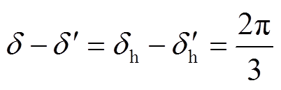 (1)
(1)式中,、分别为换相序前、后功角;下标 代表换相序瞬间。
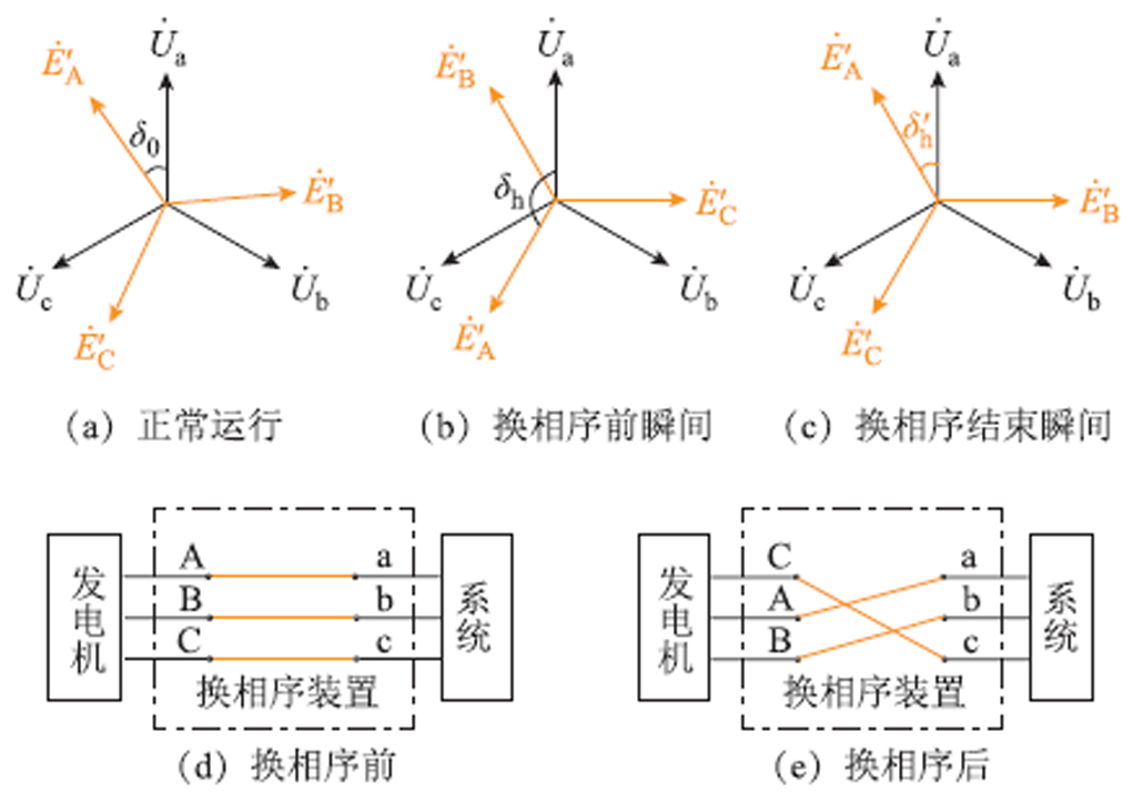
图1 换相序技术相量图及示意图
Fig.1 PSET phasor diagrams and schematic diagrams
下面从 坐标系统阐述换相序前后功角转换,首先分析换相序前后坐标系统的转换。换相序前,发电机
 坐标系统经Park变换转换为坐标系统,
 轴与
轴与 轴夹角为
轴夹角为 ;换相序后,发电机切换为
 相序,经Park变换转换为
 坐标系统,轴与
 轴夹角仍为。由于坐标系统超前坐标系统
 ,因此,坐标系统超前原坐标系统,如图2所示。
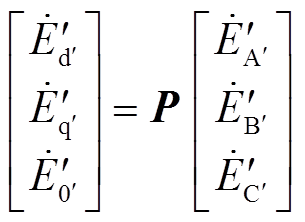
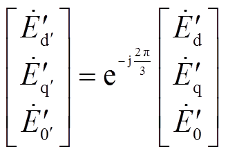
进一步通过Park变换推导、坐标系统下电动势相量的关系。换相序前瞬间,发电机电动势 、
、 经Park变换转换为
 ,从而有
,从而有
 (2)
(2)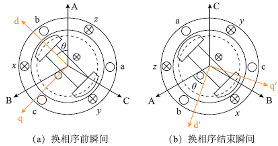
图2 Park变换示意图
Fig.2 dq0 transform diagrams
式中,为坐标系统下的发电机电动势; 为Park变换矩阵,即
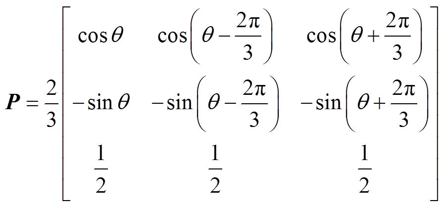 (3)
(3)式中,为轴与轴夹角。
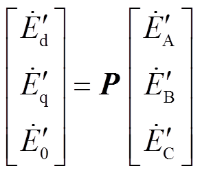
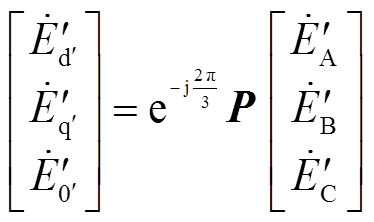
换相序结束瞬间,发电机电动势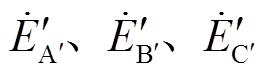 经Park变换转换为
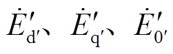 ,从而有
,从而有
 (4)
(4)式中,为坐标系统下的发电机电动势;P矩阵中,为轴与轴夹角。
比较图1b、图1c可以发现, 与
与 、
、 关系为
关系为
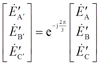 (5)
(5)将式(5)代入式(4)得
 (6)
(6)再将式(2)代入式(6)得
 (7)
(7)将图2与式(7)结合分析,图2中,换相序结束瞬间,转子位置由于惯性并未发生突变,但由于坐标系统超前原坐标系统,使得式(7)中滞后,也就是说,换相序结束瞬间,Park变换后的发电机电动势相角减小了,因此,功角减小了。
以上从、两种坐标系统阐明了换相序前后功角转换,如式(1)所示。下面分析换相序前后发电机功角特性。
假设发电机采用经典二阶模型,此时可忽略原动机、调速器、励磁系统的影响,于是,机械功率 保持不变,故障切除后电磁功率
 为[21]
为[21]
 (8)
(8)式中, 为功角,即发电机等效电动势
 与无穷大母线
 之间的角度;
 为故障切除后系统总电抗;
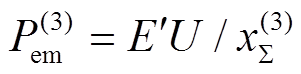 为故障切除后电磁功率最大值。
换相序后,保持不变。此外,电动势幅值 、
、 、不变,功角变为
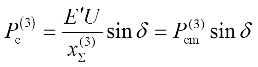
 ,于是,换相序后电磁功率
 为
为
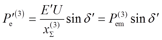 (9)
(9)将式(1)代入式(9)可得
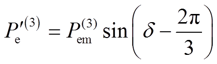 (10)
(10)将式(8)~式(10)绘制于图3,以便阐述换相序过程。图中,上标不带“′”的变量对应 坐标系,上标带“′”的变量对应
 坐标系。在
坐标系。在 处换相序时,系统功角减小,突变为
 ,且电磁功率从曲线上的
 点突变为曲线上
 点。此后,沿曲线运行,功角为
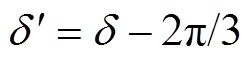 。
。
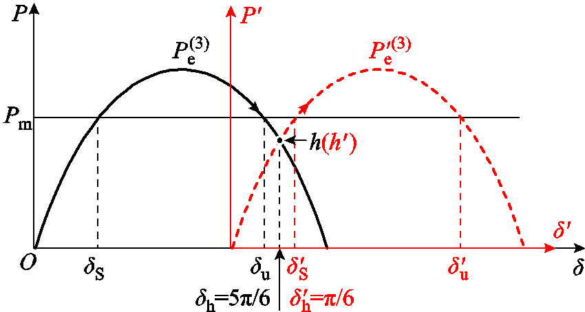
图3 换相序前后功角特性曲线
Fig.3 Power-angle curves before and after phase sequence exchanging
换相序前, 为故障切除后稳定平衡点,
 为不稳定平衡点,引用文献[22]对平衡点的描述,从而有
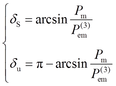 (11)
(11)设换相序后平衡点为 、
、 ,由于平衡点处满足
 ,将式(9)代入其中,解得
 (12)
(12)由于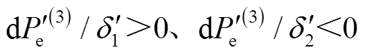 ,则为换相序后稳定平衡点,记为
 ;为换相序后不稳定平衡点,记为
 。再结合式(11)、式(12)可得
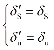 (13)
(13)式(13)表明,换相序后系统平衡点保持不变,如图3所示。
因此,换相序后功角减小,电磁功率变为,但是平衡点保持不变,如式(1)、式(9)、式(13)所示。此结论是下文能量函数分析的基础。
基于暂态能量函数法,给出换相序前、后系统总能量,进而得到换相序瞬间的能量变化量。
依据经典能量函数法[23],定义系统动能 为
为
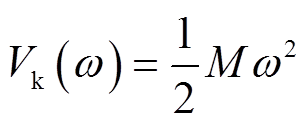 (14)
(14)式中, 为转速差;
为转速差; 为发电机惯性时间常数。
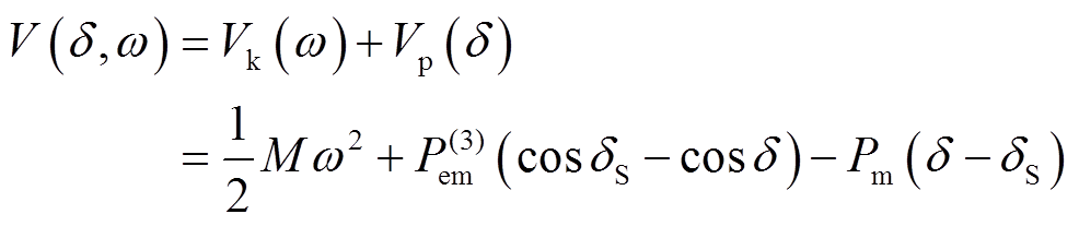
以稳定平稳点为势能参考点,定义系统势能 为
为
 (15)
(15)式中,右侧第一项为系统电抗中存储的磁能;第二项为转子的位置能量。
故障切除后至换相序前,系统总能量 为
为
 (16)
(16)当系统功角为,转速差为 时进行换相序操作,则换相序前瞬间动能为
 、势能为
、势能为 ,总能量
,总能量 为
为
在刚完成换相序操作的瞬间,功角及转速差为、 。假设换相序过程迅速,对发电机转速影响较小,则
 (18)
(18)此外,与关系如式(1)所示。此时,利用换相序前后瞬间功角及转速差的关系,即可分析换相序前后各能量变化情况。
考虑式(18)的关系,则换相序结束瞬间动能 为
为
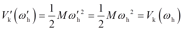 (19)
(19)因此,换相序瞬间动能保持不变,则能量变化只取决于势能变化。
换相序后,以稳定平衡点为势能参考点,则系统势能 为
为
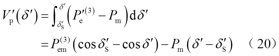
将式(1)、式(13)代入式(20)得
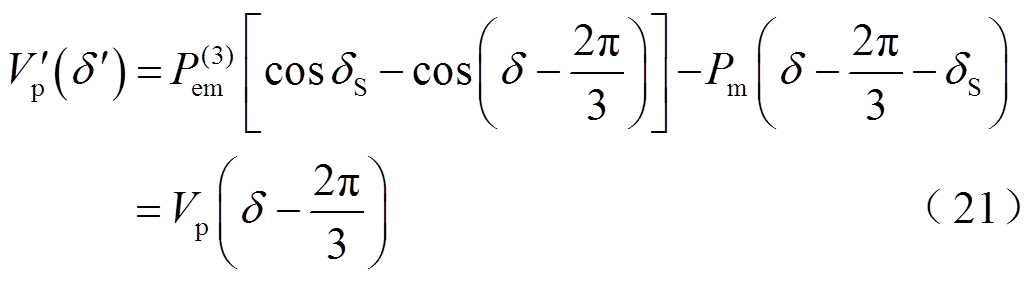
式(21)表明,在 坐标系下,
坐标系下, 相当于右向平移,由此绘制、曲线于图4b,以便后续对比与分析。
将 、
、 代入式(21),即可得到换相序结束瞬间势能
 为
为
图4  时换相序前后能量变化图
Fig.4 Energy change diagrams before and after phase sequence exchanging when
于是,换相序结束瞬间系统总能量 为
为
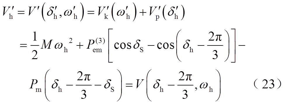
根据上述分析,可得换相序瞬间能量的变化量DV为
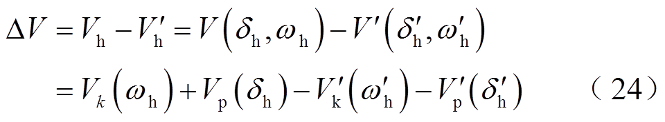
将式(19)的结论代入式(24),可得
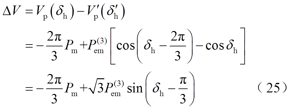
式(25)表明,总能量的变化量DV亦为势能的变化量。此外, 、的取值决定了能量变化量DV的正负。当
 时,换相序后系统总能量增大;当
 时,换相序后系统总能量减小。
从物理意义角度进一步分析DV中各项含义,式(25)中, 为转子位置势能的变化。虽然换相序瞬间转子位置不变,但参考坐标系统的改变使转子角滞后,因而转子位置势能增加了
 ;
; 为电抗中存储磁能的变化量,当该项大于0时,其计算值即为换相序瞬间磁性势能的减小量。当
 ,即时,势能减小量大于增加量,因而消减了系统能量。因此,不采取其他措施,仅通过一次或多次换相序控制使系统趋于稳定的必要条件为
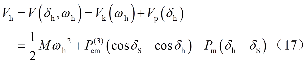
(26)将换相序前后能量变化过程绘制出来,如图4所示。图4a中,轨迹 、
、 分别为换相序前、后相轨迹,轨迹上
 点对应换相序前瞬间功角、转速差,对应能量为换相序前瞬间总能量,如式(17)所示。由于相轨迹为等能量曲线,点总能量可直观表示为等能量曲线。轨迹上
 点对应换相序结束瞬间功角
 、转速差
、转速差 ,对应能量为换相序结束瞬间总能量,如式(23)所示,则点总能量可直观表示为等能量曲线,这样,
 间总能量差值即为等能量曲线、间的总能量差值。图4b中,根据式(15)、式(21)绘制换相序前后势能变化曲线,如曲线③、④所示。
 点分别为换相序前、后瞬间势能、。由图4可以看出,在处的换相序瞬间,系统总能量由突变至点,势能由
 突变至
突变至 点。根据式(24)、式(25),间总能量差值(亦为等能量曲线、间的能量差值)与
 间势能差值相等,均为能量变化量DV。此时,,换相序减小了系统能量。
因此,换相序技术的关键在于控制瞬间能量减小,其能量变化量DV如式(25)所示。
基于上述结论,推导了换相序技术的应用条件,并以稳定裕度增量为依据,提出了换相序技术的最优控制策略。
将式(25)代入式(26)的稳定必要条件,可得
 (27)
(27)再结合式(11)的表达式,则式(27)整理为
 (28)
(28)式中,为换相序前瞬间功角。
因此,式(28)即为基于能量函数法的换相序技术应用条件。换句话说,满足式(28)条件后,则DV满足式(26),在处换相序才能够提高系统暂态稳定性。
为了进一步量化换相序技术对系统稳定性的提升程度,从稳定裕度增量角度进行对比分析。通过换相序前后系统临界能量分析,判断系统稳定性。
3.2.1 换相序前后系统稳定性判断
1)判断换相序前系统是否稳定
将故障切除时刻的功角 及转速差
及转速差 代入式(16)即可得到对应的能量为
 。此外,不采取换相序措施时,以故障切除后不稳定平衡点处的势能作为临界能量
 ,即
,即
 (29)
(29)于是,比较 与,即可判定系统是否稳定。也就是说,若
 ,则系统稳定;反之若
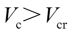 ,则系统失稳,需采取换相序控制措施,如图5中轨迹所示。
图5 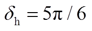 时换相序前后相轨迹
Fig.5 Phase trajectory diagram before and after phase sequence exchanging when
2)判断换相序后系统是否稳定
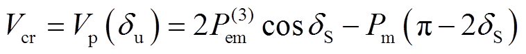
为了以故障切除时刻能量判断换相序后系统是否稳定,需分析对应的临界能量。由于直接求解较为困难,考虑到与换相序前瞬间总能量相等,故将式(24)转换为
 (30)
(30)因此,上述问题转换为求解换相序后总能量对应的临界能量,在此基础上加 ,即可得到对应的临界能量。
由图4b可知,在不稳定平衡点处,换相序后的势能取得最大值。于是,以处的势能作为对应的临界能量 ,即
,即
 (31)
(31)将式(13)代入式(31)可得
 (32)
(32)因此,对应的临界能量 为
为

于是,比较故障切除时刻能量 与其对应的临界能量
 ,即可判定该次换相序后系统是否稳定。也就是说,若
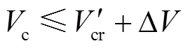 ,则该次换相序能够使系统稳定,如图5中、、轨迹
 所示;反之若
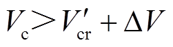 ,则该次换相序后系统仍失稳,可进行多次换相序控制,逐次减小系统能量直至系统稳定。
3.2.2 稳定裕度增量分析
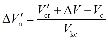
根据上述分析,以临界能量与故障切除时刻能量的差值作为系统稳定裕度的定量描述,并进行规格化处理。于是,不采取换相序措施时,稳定裕度 为[23]
为[23]
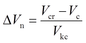 (34)
(34)式中,Vkc为故障切除时的动能,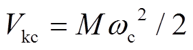 。
。
同理,采取换相序措施后,稳定裕度 为
为
 (35)
(35)稳定裕度、 小于0时,系统失稳;等于0时,为临界稳定;大于0时,系统稳定,且数值越大,系统稳定程度越高。
比较式(34)、式(35)可以发现,换相序后系统稳定裕度增量 为
为
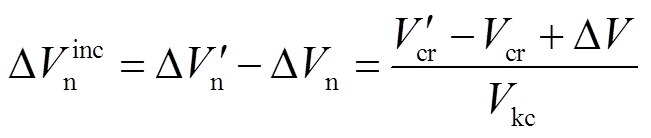 (36)
(36)再将式(29)、式(32)代入式(36),可得
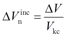 (37)
(37)式(37)表明,增加的稳定裕度 由能量变化量DV决定,DV满足式(26)的必要条件,则
 。因此,换相序提高系统稳定裕度的本质为控制瞬间能量减小。
为了实现换相序最优效果,获得最大的稳定裕度,需分析换相序最优控制策略。
由式(37)可知, 越大,换相序消减的能量越大,稳定裕度增量越大,越有利于系统稳定。因此,若能推导出DV最大时对应的换相序功角值,即可得到换相序最优控制策略。为此,令式(25)的DV表达式中保持不变,求得DV关于换相序前瞬间功角
 的导数为
的导数为
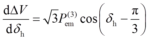 (38)
(38)为求得DV驻点,令式(38)等于0且 ,得到
,得到
 (39)
(39)将式(39)与图4b结合分析可以确定:当 时换相序,DV为正最大值,从而达到换相序最优效果。此时,稳定裕度增量最大,其数值为
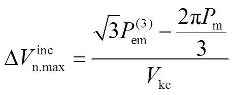 (40)
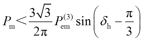
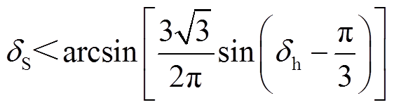
(40)因此,最优控制策略为时换相序。将代入式(28),即可得到最优控制策略对应的应用条件为
 (41)
(41)也就是说,当 满足式(41)时,最优控制策略下稳定裕度增量最大值
 必定大于0。
综上所述,应用于稳定控制的换相序技术能够极大地提高系统暂态稳定性,但是需满足式(28)的应用条件。此外,最优控制策略为功角等于 时换相序,从而获得最大稳定裕度。
算例采用文献[24]中的单机无穷大系统。初始功角 ,
, ;
; 时刻发生故障,故障期间电磁功率最大值
 ;
; 故障切除,故障切除后
 ,
, 。其他参数为
 ,
, ,阻尼
,阻尼 。为验证上述理想二阶模型下理论的准确性,本文采用数值积分法进行仿真验证,积分步长为0.001s,并根据上述能量函数公式计算各状态下的能量。
1)是否采取换相序最优控制策略的相轨迹对比如图6a所示。故障切除时刻能量 、临界能量
、临界能量 ,由于
,由于 ,系统沿轨迹
 失稳;若在功角处换相序,由式(23)、式(30)计算得,换相序后能量突变为
 ,能量减小了
 。此外,由式(33)计算得换相序的临界能量
 0.585,由于
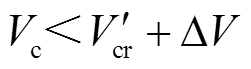 ,则系统沿轨迹趋于稳定。
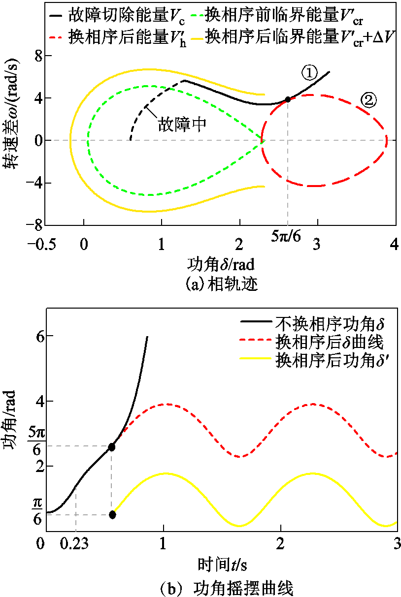
图6 是否采取换相序最优控制策略对比
Fig.6 The comparison diagrams of whether optimal control strategy of PSET is implemented
上述情况对应的功角摇摆曲线如图6b所示,不采取换相序措施时功角为 ,换相序后功角为
 。由式(34)~式(37)可得,换相序控制下,暂态稳定裕度由-0.352提高到0.244,换相序增加的稳定裕度为0.596。由此可以知道,换相序技术使系统由失稳趋于稳定,极大地提高了系统稳定裕度。
2)当采取最优控制策略时,式(28)的应用条件可整理为式(41)的形式。在上述仿真中,满足式(41)的应用条件。为了验证应用条件的正确性,进一步验证式(41)对应的临界情况,即 。此时,仿真参数修改为
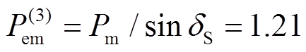 ,对应的临界情况相轨迹如图7所示。经计算,式(17)的换相序前能量
 与式(23)换相序后能量
 相等,均为0.437,于是,换相序瞬间能量变化量
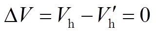 ,因而换相序后系统仍然失稳。对比图6a、图7可知,只有满足换相序技术应用条件,一次或多次换相序控制才能够减小系统能量,使系统趋于稳定。
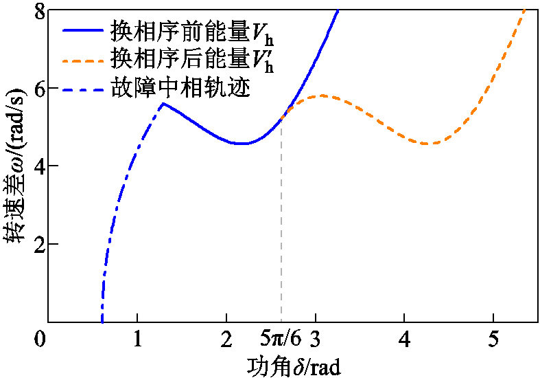
图7 临界情况仿真曲线
Fig.7 Simulation curves in the critical case
图8为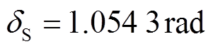 、时不满足式(41)应用条件的仿真曲线。仿真结果表明,虽然换相序后系统仍失稳,但换相序技术起延缓系统失稳作用。
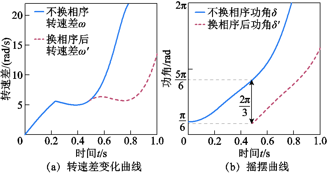
图8 不满足应用条件时仿真曲线
Fig.8 The simulation curves when the application condition is not satisfied
3)图9、表1为不同功角处换相序的仿真结果。由式(25)、式(34)~式(37)计算得不同功角处换相序的能量变化量DV、不换相序的稳定裕度、换相序后稳定裕度、稳定裕度增量,见表1所示。分析图9、表1可知,功角为时换相序,系统剩余能量最小,减小的能量DV最大,因而稳定裕度增量最大,换相序效果最优。
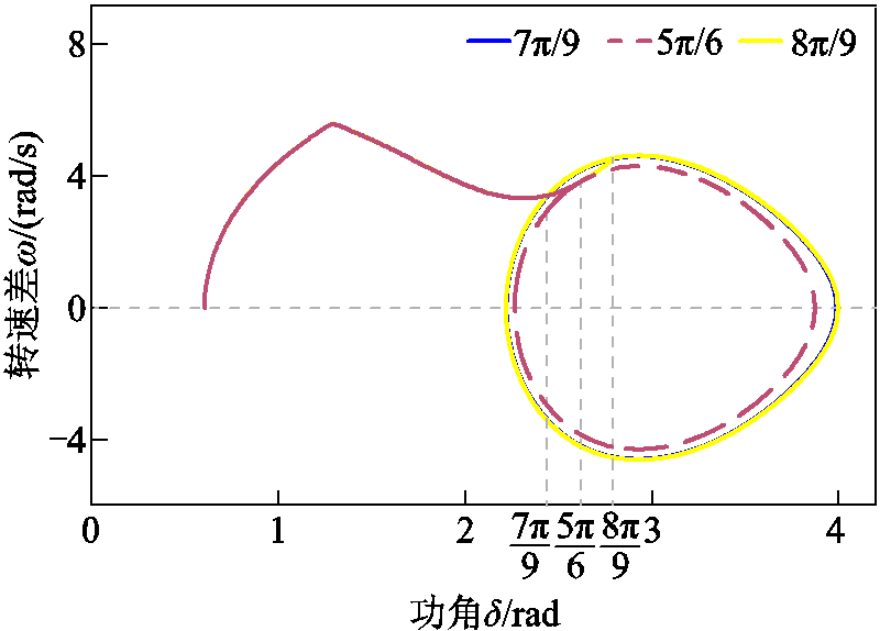
图9 不同功角下换相序的仿真曲线
Fig.9 Simulation curves of phase sequence exchanging at different power angles
表1 不同功角处换相序的仿真结果
Tab.1 Simulation results of phase sequence exchanging at different power angles

/radDV 0.2088-0.3520.1580.51 0.23530.2230.575 0.24390.2440.596 0.23490.2220.574 0.20660.1530.505
此外,还验证了多种情况,均证明了上述理论的正确性,不再赘述。
针对换相序稳定控制技术,本文分析了换相序前后系统的暂态稳定特性,采用能量函数法分析换相序前后能量变化,得到了换相序瞬间的能量变化量,并得到了如下结论:
1)从能量函数角度出发,推导了换相序技术的应用条件。
2)功角为时进行换相序控制,能够获得最大稳定裕度,实现稳定控制的最优效果。
3)通过换相序前后系统临界能量分析,推导了换相序技术对暂态稳定性的提高程度(即稳定裕度增量)。
理论分析和仿真结果均表明,本文的最优控制策略能够实现稳定控制的最优效果,并验证了应用条件的正确性。
参考文献
[1]唐飞, 刘扬, 施浩波, 等. 一种考虑风电场并网的大电网快速主动解列策略[J]. 电工技术学报, 2019, 34(10): 2092-2101. Tang Fei, Liu Yang, Shi Haobo, et al. A fast active islanding strategy for large power grid considering wind farm integration[J]. Transactions of China Electrotechnical Society, 2019, 34(10): 2092-2101.
[2]陈鹏远, 黎灿兵, 周斌, 等. 异步互联电网柔性直流输电紧急功率支援与动态区域控制偏差协调控制策略[J]. 电工技术学报, 2019, 34(14): 3025-3034. Chen Pengyuan, Li Canbing, Zhou Bin, et al. VSC-HVDC emergency power support and dynamic area control error coordinated control strategy for improving the stability of asynchronous interconnected power grids[J]. Transactions of China Electrotechnical Society, 2019, 34(14): 3025-3034.
[3]林旻威, 温步瀛. 大规模风电接入对电力系统暂态稳定性影响研究综述[J]. 电气技术, 2017, 18(4): 1-8. Lin Minwei, Wen Buying. The overview of influence of large scale wind generation on transient stability of power system[J]. Electrical Engineering, 2017, 18(4): 1-8.
[4]辛建波, 王玉麟, 舒展, 等. 特高压交直流接入对江西电网暂态稳定的影响分析[J]. 电力系统保护与控制, 2019, 47(8): 71-79. Xin Jianbo, Wang Yulin, Shu Zhan, et al. Transient stability impact analysis of UHV AC/DC access to Jiangxi power grid[J]. Power System Protection and Control, 2019, 47(8): 71-79.
[5]顾卓远, 汤涌, 孙华东, 等. 基于响应的电力系统安全稳定综合防御技术[J]. 中国电机工程学报, 2019, 39(4): 943-953. Gu Zhuoyuan, Tang Yong, Sun Huadong, et al. Study on framework of comprehensive defense architecture for power system security and stability[J]. Proceedings of the CSEE, 2019, 39(4): 943-953.
[6]石访, 张林林, 胡熊伟, 等. 基于多属性决策树的电网暂态稳定规则提取方法[J]. 电工技术学报, 2019, 34(11): 2364-2374. Shi Fang, Zhang Linlin, Hu Xiongwei, et al. Power system transient stability rules extraction based on multi-attribute decision tree[J]. Transactions of China Electrotechnical Society, 2019, 34(11): 2364-2374.
[7]刘九良, 王彤, 朱劭璇, 等. 计及保护信息的电力系统暂态稳定裕度解析算法[J]. 电工技术学报, 2020, 35(3): 542-552. Liu Jiuliang, Wang Tong, Zhu shaoxuan, et al. An analytic method for power system transient stability margin considering protection information[J]. Transactions of China Electrotechnical Society, 2020, 35(3): 542-552.
[8]孙黎霞, 白景涛, 周照宇, 等. 基于双向长短期记忆网络的电力系统暂态稳定评估[J]. 电力系统自动化, 2020, 44(13): 64-72. Sun Lixia, Bai Jingtao, Zhou Zhaoyu, et al. Transient stability assessment of power system based on bi-directional long-short-term memory network[J]. Automation of Electric Power Systems, 2020, 44(13): 64-72.
[9]韦肖燕, 李欣然, 钱军, 等. 采用储能电源辅助的暂态稳定紧急控制方法[J]. 电工技术学报, 2017, 32(18): 286-300. Wei Xiaoyan, Li Xinran, Qian Jun, et al. Power system transient stability emergency control method assisted by energy storage[J]. Transactions of China Electrotechnical Society, 2017, 32(18): 286-300.
[10]陈学通, 凌超, 薛峰, 等. 一种基于贪心算法的紧急控制策略优化搜索方法[J]. 电力系统保护与控制, 2017, 45(23): 74-81. Chen Xuetong, Ling Chao, Xue Feng, et al. A fast method of searching optimal emergency control strategy based on greedy algorithm[J]. Power System Protection and Control, 2017, 45(23): 74-81.
[11]Cresap R L, Taylor C W, Kreipe M J. Transient stability enhancement by 120-degree phase rotation[J]. IEEE Transactions on Power Apparatus and Systems, 1981, 100(2): 745-753.
[12]Song S M, Kim J Y, Choi S S, et al. New simple-structured ac solid-state circuit breaker[J]. IEEE Transactions on Industrial Electronics, 2018, 65(11): 8455-8463.
[13]卢其威, 高志宣, 滕尚甫, 等. 基于MOSFET的限流式固态断路器及其过电压抑制[J]. 电工技术学报, 2017, 32(24): 42-52. Lu Qiwei, Gao Zhixuan, Teng Shangfu, et al. Current limiting solid state circuit breaker based on MOSEFT and its over voltage suppression[J]. Transactions of China Electrotechnical Society, 2017, 32(24): 42-52.
[14]Meyer C, Schroder S, De Doncker R W. Solid-state circuit breakers and current limiters for medium-voltage systems having distributed power systems[J]. IEEE Transactions on Power Electronics, 2004, 19(5): 1333-1340.
[15]许苏迪, 刘灏, 毕天姝, 等. 一种适用于同步相量测量装置校准器的高精度相量测量方法[J]. 电工技术学报, 2020, 35(2): 372-382. Xu Sudi, Liu Hao, Bi Tianshu, et al. A high accuracy phasor estimation algorithm for phasor measurement units calibrator[J]. Transactions of China Electrotechnical Society, 2020, 35(2): 372-382.
[16]罗深增, 李银红, 石东源. 广域测量系统可观性概率评估及其在PMU优化配置中的应用[J]. 电工技术学报, 2018, 33(8): 1844-1853. Luo Shenzeng, Li Yinhong, Shi Dongyuan. Wide area monitoring system observability probabilistic evaluation and it’s application in optimal PMU placement[J]. Transactions of China Electrotechnical Society, 2018, 33(8): 1844-1853.
[17]赵晋泉, 邓晖, 吴小辰, 等. 基于广域响应的电力系统暂态稳定控制技术评述[J]. 电力系统保护与控制, 2016, 44(5): 1-9. Zhao Jinquan, Deng Hui, Wu Xiaochen, et al. Review on power system transient stability control technologies based on PMU/WAMS[J]. Power System Protection and Control, 2016, 44(5): 1-9.
[18]Huang Shaofeng, Li Yifan, Li Hui, et al. A new technology applied to power system stability control: phase sequence exchange technology[J]. IEEE Access, 2019, 7: 93002-93009.
[19]Li Yifan, Huang Shaofeng, Li Hui, et al. A new phase sequence exchanging control method for reducing impulse current and voltage[J]. IEEE Access, 2019, 7: 164734-164745.
[20]Li Yifan, Huang Shaofeng, Li Hui, et al. Application of phase sequence exchange in emergency control of a multi-machine system[J]. International Journal of Electrical Power & Energy Systems, 2020, DOI: 10.1016/j.ijepes.2020.106136.
[21]李光琦. 电力系统暂态分析[M]. 北京: 中国电力出版社, 2007.
[22]闵勇, 陈磊, 姜齐荣. 电力系统稳定分析[M]. 北京: 清华大学出版社, 2016.
[23]倪以信, 陈寿孙, 张宝霖. 动态电力系统的理论和分析[M]. 北京: 清华大学出版社, 2002.
[24]刘笙, 陈陈. 电力系统暂态稳定的能量函数分析[M]. 北京: 科学出版社, 2014.
The Condition of Phase Sequence Exchange Technology Applied to Stability Control and Optimal Control Strategy
Abstract Phase sequence exchange technology (PSET) is a scheme of power system stability control. When the system is about to lose stability, the phase sequence is quickly exchanged by the power electronic switch. The ABC phase of generator side is disconnected and then connected to cab phase of system side correspondingly, thereby reducing the power angle byand achieving the purpose of stability control. Based on the energy function method, the mutation mechanism of total energy before and after phase sequence exchanging was analyzed and the mutational energy at the instant of phase sequence exchanging was obtained. On this basis, the application condition of PSET was derived. By judging the system stability before and after phase sequence exchanging, the stability margin increment after phase sequence exchanging was given, thus analyzing the degree of improving the power system transient stability by PSET quantitatively. Based on this, the optimal control strategy of PSET was proposed. Finally, simulation results based on Matlab show that the optimal control strategy of PSET can achieve the optimal effect of stable control and obtain the maximum stability margin. Besides, the correctness of application condition is verified.
keywords:Phase sequence exchange technology, stability control, energy function analysis, transient stability, application condition, optimal control strategy
中图分类号:TM712
DOI:10.19595/j.cnki.1000-6753.tces.200457
中央高校基本科研业务费资助项目(2019QN107)。
收稿日期 2020-05-07
改稿日期 2020-08-01
黄少锋 男,1958年生,教授,博士生导师,研究方向为电力系统继电保护。E-mail:huangsf@sf-auto.com
李 慧 女,1994年生,博士研究生,研究方向为电力系统稳定与控制。E-mail:student089@163.com(通信作者)
(编辑 赫蕾)